

Gree GWH09QB-K3DNA2G, GWH09QB-K3DNB4G, GWH09QB-K3DNA5G, GWH09QB-K3DNB2G, GWH09QB-K3DNB6G Service Manual
...
GREE ELECTRIC APPLIANCES,INC.OF ZHUHAI
Change for Life
Service Manual
Models: GWH09QB-K3DNA1G
GWH09QB-K3DNA2G
GWH09QB-K3DNA5G
GWH09QB-K3DNB2G
GWH09QB-K3DNB4G
GWH09QB-K3DNB6G
GWH12QC-K3DNA1G
GWH12QC-K3DNA2G
GWH12QC-K3DNA5G
GWH12QC-K3DNB2G
GWH12QC-K3DNB4G
GWH12QC-K3DNB6G
(Refrigerant R410A)

Service Manual
Table of Contents
Part
Ⅰ
: Technical Information
.......................................................................1
1. Summary
......................................................................................................................1
2. Specications
..........................................................................................................2
2.1 Specication Sheet ...........................................................................................................2
2.2 Operation Characteristic Curve ......................................................................................10
2.3 Capacity Variation Ratio According to Temperature .......................................................10
2.4 Cooling and Heating Data Sheet in Rated Frequency ...................................................11
2.5 Noise Curve ....................................................................................................................11
3. Outline Dimension Diagram
......................................................................12
3.1 Indoor Unit ......................................................................................................................12
3.2 Outdoor Unit ...................................................................................................................13
4. Refrigerant System Diagram
....................................................................14
5. Electrical Part
.........................................................................................................15
5.1 Wiring Diagram ...............................................................................................................15
5.2 PCB Printed Diagram .....................................................................................................18
6. Function and Control
......................................................................................20
6.1 Remote Controller Introduction .....................................................................................20
6.2 Brief Description of Modes and Functions ......................................................................24
Part
Ⅱ
: Installation and Maintenance
.................................................28
7. Notes for Installation and Maintenance
..........................................28
8. Installation
................................................................................................................30
8.1 Installation Dimension Diagram ......................................................................................30
8.2 Installation Parts-checking ............................................................................................32
8.3 Selection of Installation Location ....................................................................................32
8.4 Electric Connection Requirement ...................................................................................32
8.5 Installation of Indoor Unit ................................................................................................32
8.6 Installation of Outdoor Unit .............................................................................................35
8.7 Vacuum Pumping and Leak Detection ...........................................................................36
8.8 Check after Installation and Test Operation ...................................................................36
Table of Contents

Service Manual
9. Maintenance
............................................................................................................37
9.1 Error Code List ...............................................................................................................37
9.2 Procedure of Troubleshooting ........................................................................................45
9.3 Troubleshooting for Normal Malfunction .........................................................................59
10. Exploded View and Parts List
..............................................................61
10.1 Indoor Unit ....................................................................................................................61
10.2 Outdoor Unit .................................................................................................................72
11. Removal Procedure
.......................................................................................75
11.1 Removal Procedure of Indoor Unit ...............................................................................75
11.2 Removal Procedure of Outdoor Unit ............................................................................80
Appendix:
........................................................................................................................86
Appendix 1: Reference Sheet of Celsius and Fahrenheit ....................................................86
Appendix 2: Conguration of Connection Pipe .....................................................................86
Appendix 3: Pipe Expanding Method ...................................................................................87
Appendix 4: List of Resistance for Temperature Sensor ......................................................88
Table of Contents
1
Technical Information
Service Manual
1. Summary
Part
Ⅰ
: Technical Information
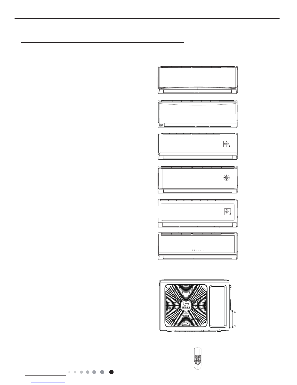
Indoor Unit
Outdoor Unit
GWH09QB-K3DNA1G/O
GWH12QC-K3DNA1G/O
A1 panel
A2 panel
A5 panel
B2 panel
B6 panel
B4 panel
Remote Controller
YAN1F1
2
Technical Information
Service Manual
2. Specications
2.1 Specication Sheet
Parameter Unit Value
Model
1.GWH09QB-K3DNA1G 2.GWH09QB-K3DNA5G
3.GWH09QB-K3DNB2G 4.GWH09QB-K3DNB4G
5.GWH09QB-K3DNB6G
Product Code
1.CB419005501 2.CB425003501
3.CB432002201 4.CB434002301
5.CB435000401
Power
Supply
Rated Voltage V~ 220-240
Rated Frequency Hz 50
Phases 1
Power Supply Mode Outdoor
Cooling Capacity(Min~Max) W 2600(450~3230)
Heating Capacity(Min~Max) W 2800(450~4100)
Cooling Power Input(Min~Max) W 805(200~1420)
Heating Power Input(Min~Max) W 755(200~1550)
Cooling Current Input A 3.7
Heating Current Input A 3.4
Rated Input W 1550
Rated Current A 6.9
Air Flow Volume(SH/H/M//L/SL) m3/h 560/490/430/330/-
Dehumidifying Volume L/h 0.8
EER W/W 3.23
COP W/W 3.71
SEER W/W 6.1
HSPF W/W /
Application Area m
2
12-18
Indoor
Unit
Indoor Unit Model
1.GWH09QB-K3DNA1G/I 2.GWH09QB-K3DNA5G/I
3.GWH09QB-K3DNB2G/I 4.GWH09QB-K3DNB4G/I
5.GWH09QB-K3DNB6G/I
Indoor Unit Product Code
1.CB419N05501 2.CB425N03500
3.CB432N02200 4.CB434N02300
5.CB435N00400
Fan Type Cross-ow
Fan Diameter Length(DXL) mm Ф98X580
Cooling Speed(SH/H/M//L/SL) r/min 1300/1200/1050/800/Heating Speed(SH/H/M//L/SL) r/min 1300/1200/1050/900/-
Fan Motor Power Output W 20
Fan Motor RLA A 0.215
Fan Motor Capacitor μF 1
Evaporator Form Aluminum Fin-copper Tube
Evaporator Pipe Diameter mm Ф5
Evaporator Row-n Gap mm 2-1.4
Evaporator Coil Length (LXDXW) mm 584X22.8X266.7
Swing Motor Model MP24AA
Swing Motor Power Output W 1.5
Fuse Current A 3.15
Sound Pressure Level(SH/H/M//L/SL) dB (A) 39/36/32/26/-
Sound Power Level(SH/H/M//L/SL) dB (A) 55/52/44/38/-
Dimension (WXHXD) mm 790X275X200
Dimension of Carton Box (LXWXH) mm 863X268X352
Dimension of Package(LXWXH) mm 866X271X367
Net Weight kg 9
Gross Weight kg 11
3
Technical Information
Service Manual
The above data is subject to change without notice. Please refer to the nameplate of the unit.
Outdoor
Unit
Outdoor Unit Model GWH09QB-K3DNA1G/O
Outdoor Unit Product Code CB419W05501
Compressor Manufacturer ZHUHAI LANDA COMPRESSOR CO.,LTD.
Compressor Model QXA-A086zC190
Compressor Oil RB68EP
Compressor Type Rotary
Compressor LRA. A 40
Compressor RLA A 3.1
Compressor Power Input W 850
Compressor Overload Protector 1NT11L-6233
Throttling Method Electron expansion valve
Set Temperature Range ºC 16~30
Cooling Operation Ambient Temperature
Range
ºC -15~43
Heating Operation Ambient Temperature
Range
ºC -20~24
Condenser Form Aluminum Fin-copper Tube
Condenser Pipe Diameter mm Φ7
Condenser Rows-n Gap mm 1-1.4
Condenser Coil Length (LXDXW) mm 710X19.05X508
Fan Motor Speed rpm 900
Fan Motor Power Output W 30
Fan Motor RLA A 0.36
Fan Motor Capacitor μF /
Outdoor Unit Air Flow Volume m3/h 1600
Fan Type Axial-ow
Fan Diameter mm Φ400
Defrosting Method Automatic Defrosting
Climate Type T1
Isolation I
Moisture Protection IP24
Permissible Excessive Operating
Pressure for the Discharge Side
MPa 4.3
Permissible Excessive Operating
Pressure for the Suction Side
MPa 2.5
Sound Pressure Level (H/M/L) dB (A) 52/-/-
Sound Power Level (H/M/L) dB (A) 61/-/-
Dimension(WXHXD) mm 776X540X320
Dimension of Carton Box (LXWXH) mm 848X360X580
Dimension of Package(LXWXH) mm 851X363X595
Net Weight kg 28
Gross Weight kg 31
Refrigerant R410A
Refrigerant Charge kg 0.7
Connection
Pipe
Connection Pipe Length m 5
Connection Pipe Gas Additional Charge g/m 20
Outer Diameter Liquid Pipe mm Φ6
Outer Diameter Gas Pipe mm Φ9.52
Max Distance Height m 10
Max Distance Length m 15
Note: The connection pipe applies metric diameter.
4
Technical Information
Service Manual
Parameter Unit Value
Model
1.GWH09QB-K3DNA1G 2.GWH09QB-K3DNA2G
3.GWH09QB-K3DNB4G 4.GWH09QB-K3DNB6G
Product Code
1.CB419005500 2.CB426001200
3.CB434002302 4.CB435000403
Power
Supply
Rated Voltage V~ 220-240
Rated Frequency Hz 50
Phases 1
Power Supply Mode Outdoor
Cooling Capacity(Min~Max) W 2600(450~3230)
Heating Capacity(Min~Max) W 2800(450~4100)
Cooling Power Input(Min~Max) W 805(200~1420)
Heating Power Input(Min~Max) W 755(200~1550)
Cooling Current Input A 3.7
Heating Current Input A 3.4
Rated Input W 1550
Rated Current A 6.9
Air Flow Volume(SH/H/M//L/SL) m3/h 560/490/430/330/-
Dehumidifying Volume L/h 0.8
EER W/W 3.23
COP W/W 3.71
SEER W/W 6.1
HSPF W/W /
Application Area m
2
12-18
Indoor
Unit
Indoor Unit Model
1.GWH09QB-K3DNA1G/I 2.GWH09QB-K3DNA2G/I
3.GWH09QB-K3DNB4G/I 4.GWH09QB-K3DNB6G/I
Indoor Unit Product Code
1.CB419N05500 2.CB426N01200
3.CB434N02302 4.CB435N00403
Fan Type Cross-ow
Fan Diameter Length(DXL) mm Ф98X580
Cooling Speed(SH/H/M//L/SL) r/min 1300/1200/1050/800/Heating Speed(SH/H/M//L/SL) r/min 1300/1200/1050/900/-
Fan Motor Power Output W 20
Fan Motor RLA A 0.215
Fan Motor Capacitor μF 1
Evaporator Form Aluminum Fin-copper Tube
Evaporator Pipe Diameter mm Ф5
Evaporator Row-n Gap mm 2-1.4
Evaporator Coil Length (LXDXW) mm 584X22.8X266.7
Swing Motor Model MP24AA
Swing Motor Power Output W 1.5
Fuse Current A 3.15
Sound Pressure Level(SH/H/M//L/SL) dB (A) 39/36/32/26/-
Sound Power Level(SH/H/M//L/SL) dB (A) 55/52/44/38/-
Dimension (WXHXD) mm 790X275X200
Dimension of Carton Box (LXWXH) mm 863X268X352
Dimension of Package(LXWXH) mm 866X271X367
Net Weight kg 9
Gross Weight kg 11
5
Technical Information
Service Manual
The above data is subject to change without notice. Please refer to the nameplate of the unit.
Outdoor
Unit
Outdoor Unit Model GWH09QB-K3DNA1G/O
Outdoor Unit Product Code CB419W05500
Compressor Manufacturer ZHUHAI LANDA COMPRESSOR CO.,LTD.
Compressor Model QXA-A086zC190
Compressor Oil RB68EP
Compressor Type Rotary
Compressor LRA. A 40
Compressor RLA A 3.1
Compressor Power Input W 850
Compressor Overload Protector 1NT11L-6233
Throttling Method Electron expansion valve
Set Temperature Range ºC 16~30
Cooling Operation Ambient Temperature
Range
ºC -15~43
Heating Operation Ambient Temperature
Range
ºC -15~24
Condenser Form Aluminum Fin-copper Tube
Condenser Pipe Diameter mm Φ7
Condenser Rows-n Gap mm 1-1.4
Condenser Coil Length (LXDXW) mm 710X19.05X508
Fan Motor Speed rpm 900
Fan Motor Power Output W 30
Fan Motor RLA A 0.36
Fan Motor Capacitor μF /
Outdoor Unit Air Flow Volume m3/h 1600
Fan Type Axial-ow
Fan Diameter mm Φ400
Defrosting Method Automatic Defrosting
Climate Type T1
Isolation I
Moisture Protection IP24
Permissible Excessive Operating
Pressure for the Discharge Side
MPa 4.3
Permissible Excessive Operating
Pressure for the Suction Side
MPa 2.5
Sound Pressure Level (H/M/L) dB (A) 52/-/-
Sound Power Level (H/M/L) dB (A) 61/-/-
Dimension(WXHXD) mm 776X540X320
Dimension of Carton Box (LXWXH) mm 848X360X580
Dimension of Package(LXWXH) mm 851X363X595
Net Weight kg 28
Gross Weight kg 31
Refrigerant R410A
Refrigerant Charge kg 0.7
Connection
Pipe
Connection Pipe Length m 5
Connection Pipe Gas Additional Charge g/m 20
Outer Diameter Liquid Pipe mm Φ6
Outer Diameter Gas Pipe mm Φ9.52
Max Distance Height m 10
Max Distance Length m 15
Note: The connection pipe applies metric diameter.
6
Technical Information
Service Manual
Parameter Unit Value
Model
1.GWH12QC-K3DNA1G
2.GWH12QC-K3DNA5G
3.GWH12QC-K3DNB2G
4.GWH12QC-K3DNB4G
5.GWH12QC-K3DNB6G
GWH12QC-K3DNA2G
Product Code
1.CB419005401 2.CB425003601
3.CB432002101 4.CB434002101
5.CB435000101
CB426001301
Power
Supply
Rated Voltage V~ 220-240 220-240
Rated Frequency Hz 50 50
Phases 1 1
Power Supply Mode Outdoor Outdoor
Cooling Capacity(Min~Max) W 3500(600~3960) 3500(600~3960)
Heating Capacity(Min~Max) W 3670(600~5130) 3670(600~5130)
Cooling Power Input(Min~Max) W 1084(200~1550) 1084(200~1550)
Heating Power Input(Min~Max) W 989(220~1650) 989(220~1650)
Cooling Current Input A 5.2 5.2
Heating Current Input A 5.0 5.0
Rated Input W 1650 1650
Rated Current A 7.3 7.3
Air Flow Volume(SH/H/M//L/SL) m3/h 660/540/460/330/- 660/540/460/330/-
Dehumidifying Volume L/h 1.4 1.4
EER W/W 3.23 3.23
COP W/W 3.71 3.71
SEER W/W 6.1 6.1
HSPF W/W / /
Application Area m
2
16-24 16-24
Indoor
Unit
Indoor Unit Model
1.GWH12QC-K3DNA1G/I
2.GWH12QC-K3DNA5G/I
3.GWH12QC-K3DNB2G/I
4.GWH12QC-K3DNB4G/I
5.GWH12QC-K3DNB6G/I
GWH12QC-K3DNA2G/I
Indoor Unit Product Code
1.CB419N05401 2.CB425N03600
3.CB432N02101 4.CB434N02100
5.CB435N00100
CB426N01300
Fan Type Cross-ow Cross-ow
Fan Diameter Length(DXL) mm Ф98X633.5 Ф98X633.5
Cooling Speed(SH/H/M//L/SL) r/min 1350/1200/1050/850/- 1350/1200/1050/850/Heating Speed(SH/H/M//L/SL) r/min 1300/1150/1000/900/- 1300/1150/1000/900/-
Fan Motor Power Output W 20 20
Fan Motor RLA A 0.31 0.31
Fan Motor Capacitor μF 1.5 1.5
Evaporator Form Aluminum Fin-copper Tube Aluminum Fin-copper Tube
Evaporator Pipe Diameter mm Ф5 Ф5
Evaporator Row-n Gap mm 2-1.4 2-1.4
Evaporator Coil Length (LXDXW) mm 635X22.8X306.3 635X22.8X306.3
Swing Motor Model MP24BA MP24BA
Swing Motor Power Output W 1.5 1.5
Fuse Current A 3.15 3.15
Sound Pressure Level(SH/H/M//L/SL) dB (A) 42/39/33/26/- 42/39/33/26/-
Sound Power Level(SH/H/M//L/SL) dB (A) 57/53/45/42/- 57/53/45/42/-
Dimension (WXHXD) mm 845X289X209 845X289X209
Dimension of Carton Box (LXWXH) mm 918X278X364 918X278X364
Dimension of Package(LXWXH) mm 921X281X379 921X281X379
Net Weight kg 10 10
Gross Weight kg 12 12.5
7
Technical Information
Service Manual
The above data is subject to change without notice. Please refer to the nameplate of the unit.
Outdoor
Unit
Outdoor Unit Model GWH12QC-K3DNA1G/O
Outdoor Unit Product Code CB419W05401
Compressor Manufacturer ZHUHAI LANDA COMPRESSOR CO.,LTD.
Compressor Model QXA-A086zC190
Compressor Oil RB68EP
Compressor Type Rotary
Compressor LRA. A 40
Compressor RLA A 3.1
Compressor Power Input W 850
Compressor Overload Protector 1NT11L-6233
Throttling Method Electron expansion valve
Set Temperature Range ºC 16~30
Cooling Operation Ambient Temperature
Range
ºC -15~43
Heating Operation Ambient Temperature
Range
ºC -20~24
Condenser Form Aluminum Fin-copper Tube
Condenser Pipe Diameter mm Φ7
Condenser Rows-n Gap mm 2-1.4
Condenser Coil Length (LXDXW) mm 710X38.1X506
Fan Motor Speed rpm 900
Fan Motor Power Output W 30
Fan Motor RLA A 0.36
Fan Motor Capacitor μF /
Outdoor Unit Air Flow Volume m3/h 1600
Fan Type Axial-ow
Fan Diameter mm Φ400
Defrosting Method Automatic Defrosting
Climate Type T1
Isolation I
Moisture Protection IP24
Permissible Excessive Operating
Pressure for the Discharge Side
MPa 4.3
Permissible Excessive Operating
Pressure for the Suction Side
MPa 2.5
Sound Pressure Level (H/M/L) dB (A) 53/-/-
Sound Power Level (H/M/L) dB (A) 62/-/-
Dimension(WXHXD) mm 776X540X320
Dimension of Carton Box (LXWXH) mm 848X360X580
Dimension of Package(LXWXH) mm 851X363X595
Net Weight kg 29
Gross Weight kg 32
Refrigerant R410A
Refrigerant Charge kg 0.85
Connection
Pipe
Connection Pipe Length m 5
Connection Pipe Gas Additional Charge g/m 20
Outer Diameter Liquid Pipe mm Ф6
Outer Diameter Gas Pipe mm Ф9.52
Max Distance Height m 10
Max Distance Length m 20
Note: The connection pipe applies metric diameter.
8
Technical Information
Service Manual
Parameter Unit Value
Model
1.GWH12QC-K3DNA1G 2.GWH12QC-K3DNA5G
2.GWH12QC-K3DNB2G 4.GWH12QC-K3DNB4G
3.GWH12QC-K3DNB6G
Product Code
1.CB419005400 2.CB425003602
2.CB432002100 4.CB434002102
3.CB435000100
Power
Supply
Rated Voltage V~ 220-240
Rated Frequency Hz 50
Phases 1
Power Supply Mode Outdoor
Cooling Capacity(Min~Max) W 3500(600~3960)
Heating Capacity(Min~Max) W 3670(600~5130)
Cooling Power Input(Min~Max) W 1084(200~1550)
Heating Power Input(Min~Max) W 989(220~1650)
Cooling Current Input A 5.2
Heating Current Input A 5.0
Rated Input W 1650
Rated Current A 7.3
Air Flow Volume(SH/H/M//L/SL) m3/h 660/540/460/330/-
Dehumidifying Volume L/h 1.4
EER W/W 3.23
COP W/W 3.71
SEER W/W 6.1
HSPF W/W /
Application Area m
2
16-24
Indoor
Unit
Indoor Unit Model
1.GWH12QC-K3DNA1G/I 2.GWH12QC-K3DNA5G/I
3.GWH12QC-K3DNB2G/I 4.GWH12QC-K3DNB4G/I
5.GWH12QC-K3DNB6G/I
Indoor Unit Product Code
1.CB419N05400 2.CB425N03602
3.CB432N02100 4.CB434N02102
5.CB435N00100
Fan Type Cross-ow
Fan Diameter Length(DXL) mm Ф98X633.5
Cooling Speed(SH/H/M//L/SL) r/min 1350/1200/1050/850/Heating Speed(SH/H/M//L/SL) r/min 1300/1150/1000/900/-
Fan Motor Power Output W 20
Fan Motor RLA A 0.31
Fan Motor Capacitor μF 1.5
Evaporator Form Aluminum Fin-copper Tube
Evaporator Pipe Diameter mm Ф5
Evaporator Row-n Gap mm 2-1.4
Evaporator Coil Length (LXDXW) mm 635X22.8X306.3
Swing Motor Model MP24BA
Swing Motor Power Output W 1.5
Fuse Current A 3.15
Sound Pressure Level(SH/H/M//L/SL) dB (A) 42/39/33/26/-
Sound Power Level(SH/H/M//L/SL) dB (A) 57/53/45/42/-
Dimension (WXHXD) mm 845X289X209
Dimension of Carton Box (LXWXH) mm 918X278X364
Dimension of Package(LXWXH) mm 921X281X379
Net Weight kg 10
Gross Weight kg 12

9
Technical Information
Service Manual
The above data is subject to change without notice. Please refer to the nameplate of the unit.
Outdoor
Unit
Outdoor Unit Model GWH12QC-K3DNA1G/O
Outdoor Unit Product Code CB419W05400
Compressor Manufacturer ZHUHAI LANDA COMPRESSOR CO.,LTD.
Compressor Model QXA-A086zC190
Compressor Oil RB68EP
Compressor Type Rotary
Compressor LRA. A 40
Compressor RLA A 3.1
Compressor Power Input W 850
Compressor Overload Protector 1NT11L-6233
Throttling Method Electron expansion valve
Set Temperature Range ºC 16~30
Cooling Operation Ambient Temperature
Range
ºC -15~43
Heating Operation Ambient Temperature
Range
ºC -15~24
Condenser Form Aluminum Fin-copper Tube
Condenser Pipe Diameter mm Φ7
Condenser Rows-n Gap mm 2-1.4
Condenser Coil Length (LXDXW) mm 710X38.1X506
Fan Motor Speed rpm 900
Fan Motor Power Output W 30
Fan Motor RLA A 0.36
Fan Motor Capacitor μF /
Outdoor Unit Air Flow Volume m3/h 1600
Fan Type Axial-ow
Fan Diameter mm Φ400
Defrosting Method Automatic Defrosting
Climate Type T1
Isolation I
Moisture Protection IP24
Permissible Excessive Operating
Pressure for the Discharge Side
MPa 4.3
Permissible Excessive Operating
Pressure for the Suction Side
MPa 2.5
Sound Pressure Level (H/M/L) dB (A) 53/-/-
Sound Power Level (H/M/L) dB (A) 62/-/-
Dimension(WXHXD) mm 776X540X320
Dimension of Carton Box (LXWXH) mm 848X360X580
Dimension of Package(LXWXH) mm 851X363X595
Net Weight kg 29
Gross Weight kg 32
Refrigerant R410A
Refrigerant Charge kg 0.85
Connection
Pipe
Connection Pipe Length m 5
Connection Pipe Gas Additional Charge g/m 20
Outer Diameter Liquid Pipe mm Ф6
Outer Diameter Gas Pipe mm Ф9.52
Max Distance Height m 10
Max Distance Length m 20
Note: The connection pipe applies metric diameter.
10
Technical Information
Service Manual
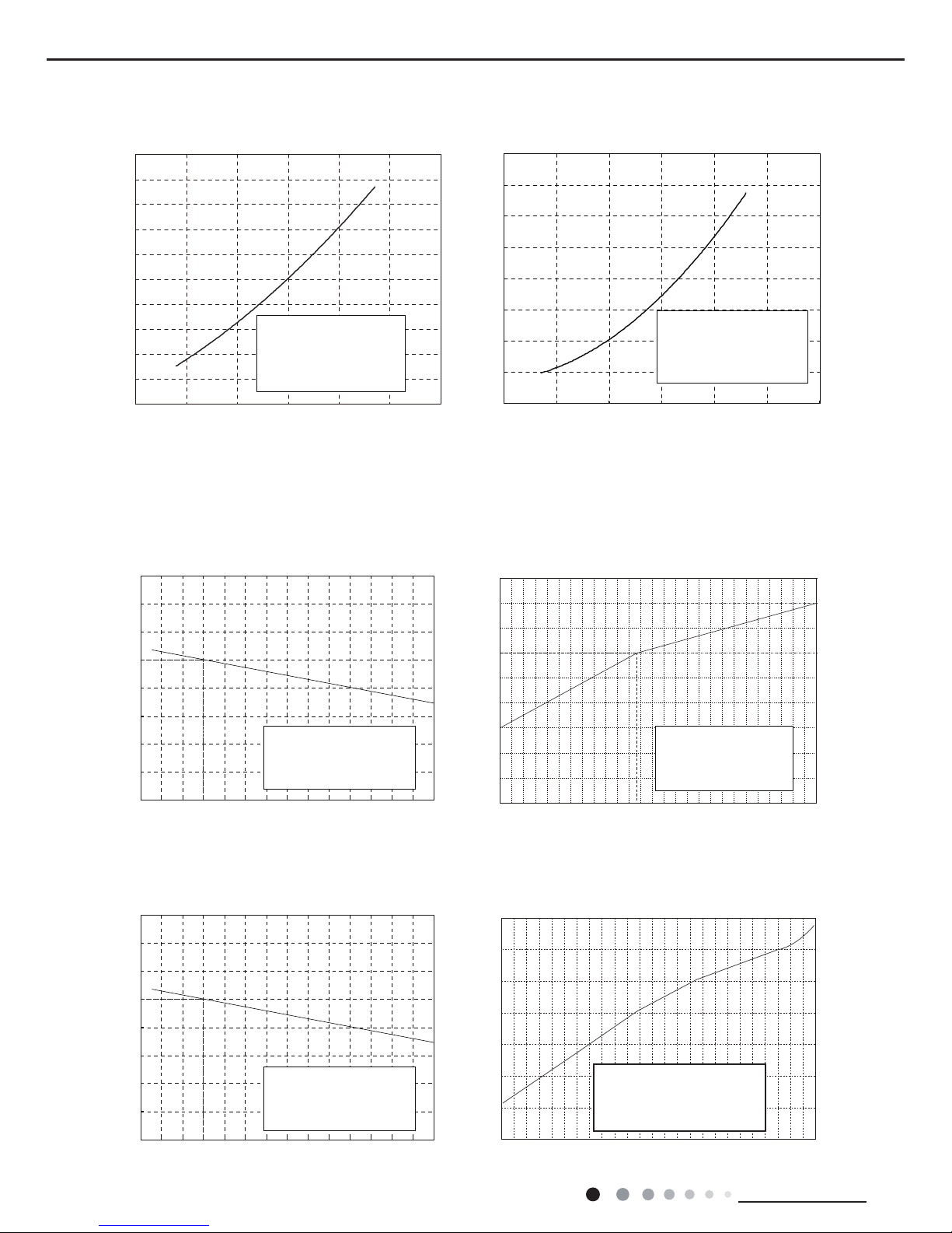
2.2 Operation Characteristic Curve
2.3 Capacity Variation Ratio According to Temperature
Compressor Speed(rps)
Compressor Speed(rps)
Cooling
Heating
Current(A)
Current(A)
50
60
70
80
90
100
110
120
130
32 33 34 35 36 37 38 39 40 41 42 43 44 45 46
Capacity ratio(%)
Outdoor temp. (°C)
Capacity ratio(%)
gnitaeHgnilooC
gnitaeHgnilooC
-20-15 -10-50
51
0
110
120
130
100
90
80
70
60
50
40
Outdoor temp.(°C)
0
1
2
3
4
5
6
7
8
9
10
020406080100 120
WB19
°C
0
1
2
3
4
5
6
7
8
020406080 100
120
50
60
70
80
90
100
110
120
130
32 33 34 35 36 37 38 39 40 41 42 43 44 45 46
Capacity ratio(%)
Outdoor temp. (°C)
Capacity ratio(
%)
–15 –10 –5
110
100
90
80
70
60
50
40
05
71
0
Conditions
Indoor:DB20°C
Indoor air flow:Super High
Pipe length:5m
Outdoor temp.(°C)
Condition
Indoor:DB27°C WB19°C
Indoor air flow:
High
Pipe length:5m
Condition
Indoor:DB27°C WB19°C
Indoor air flow:
High
Pipe length:5m
Condition
Indoor:DB20°C
Indoor air flow:
High
Pipe length:5m
Condition
Indoor:DB 27°C
Indoor air flow: Super High
Pipe length:5m
Voltage:230V
Condition
Indoor:DB 20°C
Indoor air flow: Super High
Pipe length:5m
Voltage:230V
Heating operation ambient temperature range is -20ºC~24ºC
Heating operation ambient temperature range is -15ºC~24ºC
11
Technical Information
Service Manual
2.4 Cooling and Heating Data Sheet in Rated Frequency
Rated cooling
condition(°C)
(DB/WB)
Model
Pressure of gas pipe
connecting indoor and
outdoor unit
Inlet and outlet pipe
temperature of heat
exchanger
Fan speed of
indoor unit
Fan speed of
outdoor unit
Compressor
frequency
(Hz)
Indoor Outdoor P (MPa) T1 (°C) T2 (°C)
27/19 35/24
09K
0.9 to 1.1 12 to 14 75 to 37 Super High High
52
12K 72
Rated heating
condition(°C)
(DB/WB)
Model
Pressure of gas pipe
connecting indoor and
outdoor unit
Inlet and outlet pipe
temperature of heat
exchanger
Fan speed of
indoor unit
Fan speed of
outdoor unit
Compressor
frequency
(Hz)
Indoor Outdoor P (MPa) T1 (°C) T2 (°C)
20/- 7/6
09K
2.2 to 2.4 70 to 35 2 to 4 Super High High
65
12K 77
Instruction:
T1: Inlet and outlet pipe temperature of evaporator
T2: Inlet and outlet pipe temperature of condenser
P: Pressure at the side of big valve
Connection pipe length: 5 m.
Cooling:
Heating:
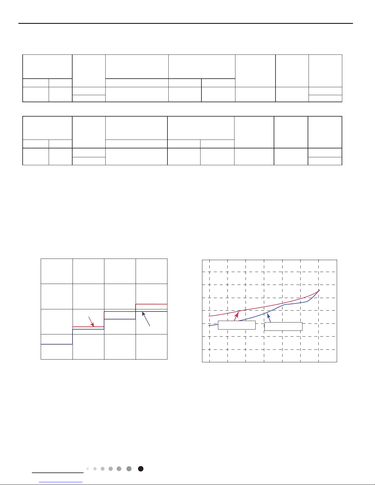
2.5 Noise Curve
Indoor side noise when blowing Outdoor side noise when blowing
Indoor fan motor rotating speed Compressor frequency(Hz)
Noise/dB(A)
50
60
30
40
20
Low
Middle
High
Super High
12K
09K
40
42
44
46
48
50
52
54
56
20 4030 50 60 70 80
90
Noise dB(A)
09&12K Cooling
09&12K Heating
12
Technical Information
Service Manual
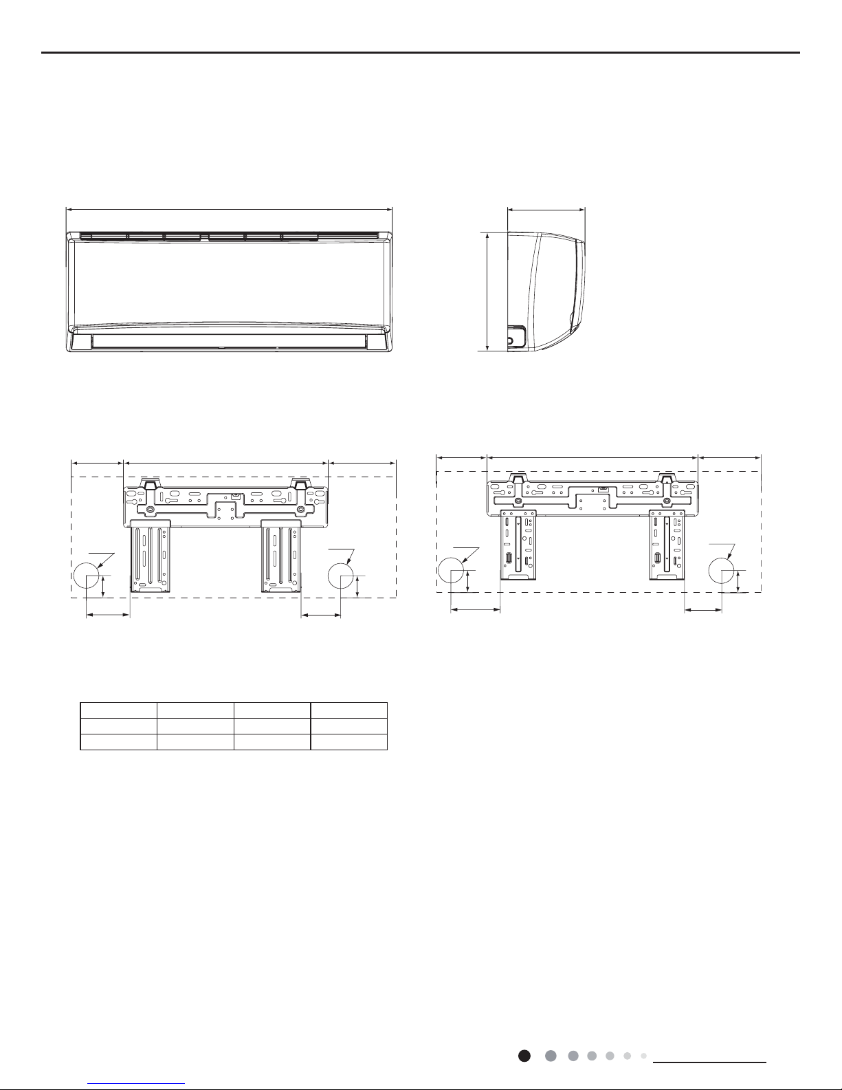
3. Outline Dimension Diagram
3.1 Indoor Unit
Unit:mm
Model W H D
09K 790 275 200
12K 845 289 209
W
12K
09K
D
H
90
150
54
168.5 462 159.5
Φ55
Φ55
54
123.5542 179.5
83.2
124.7
35
Φ55
Φ55
35
13
Technical Information
Service Manual
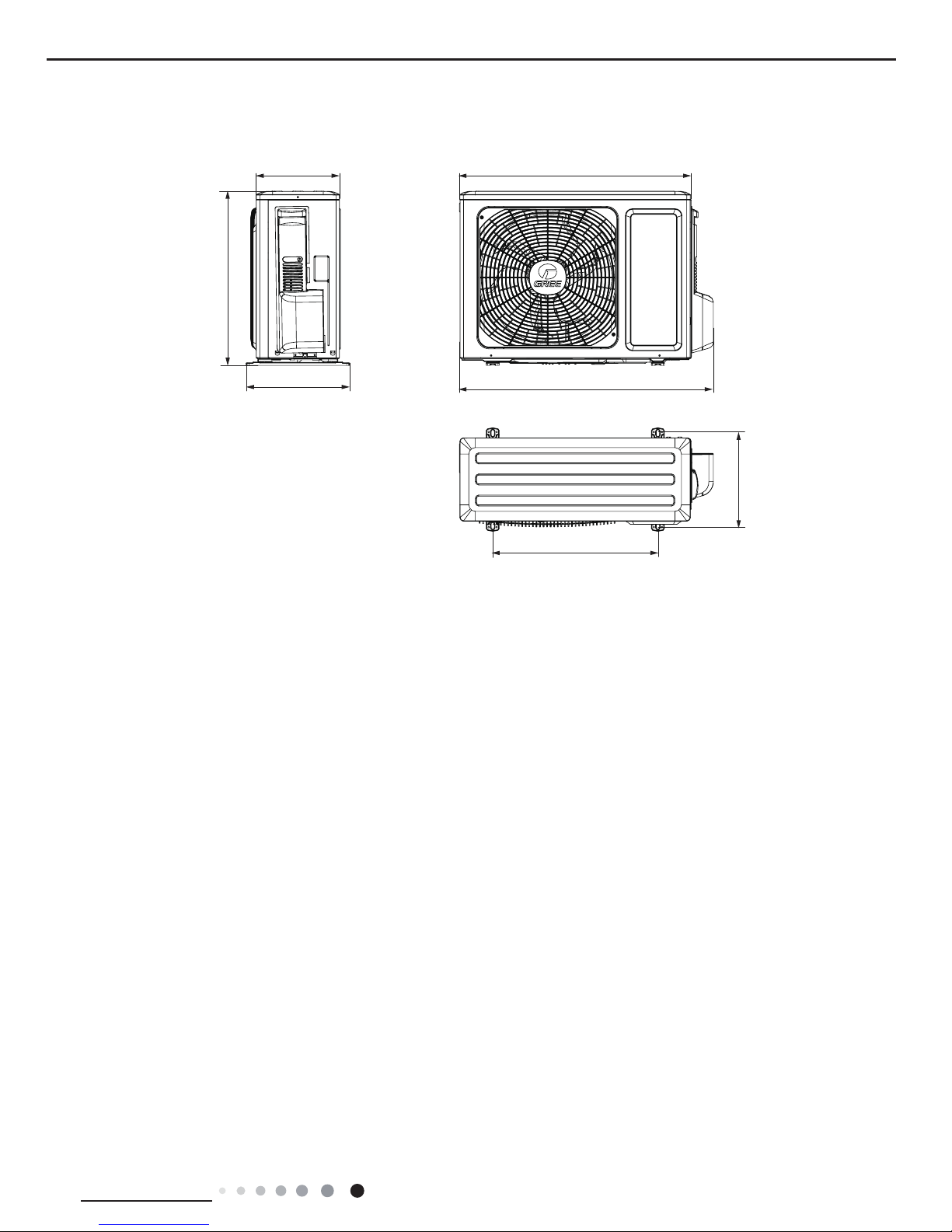
3.2 Outdoor Unit
712
776
257
320
540
286
510
Unit:mm
14
Technical Information
Service Manual
Indoor unit
Outdoor unit
COOLING
HEATING
4-Way valve
Discharge
Suction
Heat
exchanger
(evaporator)
Heat
exchanger
(condenser)
Valve
Valve
Liquid pipe
side
Gas pipe
side
Strainer
Electron
expansion
valve
Strainer
Capillary
Accumlator
Compressor
4. Refrigerant System Diagram
Connection pipe specication:
Liquid pipe:1/4" (6mm)
Gas pipe:3/8" (9.52mm)
15
Technical Information
Service Manual
5. Electrical Part
5.1 Wiring Diagram
● Indoor Unit
● Instruction
Symbol Symbol Color Symbol Symbol Color Symbol Name
WH White GN Green CAP Jumper cap
YE Yellow BN Brown COMP Compressor
RD Red BU Blue Grounding wire
YEGN Yellow/Green BK Black / /
VT Violet OG Orange / /
Note: Jumper cap is used to determine fan speed and the swing angle of horizontal lover for this model.
GWH09QB-K3DNA1G/I(CB419N05501) GWH09QB-K3DNA2G/I(CB426N01200) GWH09QB-K3DNB2G/I(CB432N02200)
GWH09QB-K3DNB4G/I(CB434N02300) GWH09QB-K3DNB6G/I(CB435N00400) GWH12QC-K3DNA1G/I(CB419N05401)
GWH12QC-K3DNA2G/I(CB426N01300) GWH12QC-K3DNA5G/I(CB425N03602) GWH12QC-K3DNB2G/I(CB432N02101)
GWH12QC-K3DNB4G/I(CB434N02100) GWH12QC-K3DNB6G/I(CB435N00100)
76(1625
7(03
6(1625
7(03
6(1625
57
5220
78%(
67(33,1*
',63/$<
35,17('&,5&8,7%2$5'
5(&(,9(5$1'
',63/$<%2$5'
&$%/(
&211(&7,1*
6:,1*8'
02725
%/2&.
7(50,1$/
$3
-803
&$3
%8
%.
<(*1
(9$325$725
3(
;7
1
0
287'22581,7
$3
3*
*(1(5$725
&2/'3/$60$
)$102725
0
5' %8
+($/7+1
+($/7+/
3*)
',63
',63
%1
<(*1
57
1
&20287
/
%8
%.
%1
/
/
16
Technical Information
Service Manual
● Outdoor Unit
GWH09QB-K3DNA1G/O(CB419W05501) GWH12QC-K3DNA1G/O(CB419W05401)
GWH09QB-K3DNA1G/I(CB419N05500) GWH09QB-K3DNB4G/I(CB434N02302) GWH09QB-K3DNA5G/I(CB425N03500)
GWH09QB-K3DNB6G/I(CB435N00403) GWH12QC-K3DNB4G/I(CB434N02102) GWH12QC-K3DNA1G/I(CB419N05400)
GWH12QC-K3DNB2G/I(CB432N02100) GWH12QC-K3DNA5G/I(CB425N03600)
76(1625
7(03
6(1625
7(03
6(1625
57
5220
78%(
67(33,1*
',63/$<
35,17('&,5&8,7%2$5'
5(&(,9(5$1'
',63/$<%2$5'
&$%/(
&211(&7,1*
6:,1*8'
02725
%/2&.
7(50,1$/
$3
-803
&$3
%8
%.
<(*1
(9$325$725
3(
;7
1
0
287'22581,7
$3
3*
)$102725
0
3*)
',63
',63
%1
<(*1
57
1
&20287
/
%8
%.
%1
/
/
/
3(
/
%8
:
9
8
5'
<(
&203
&203
/;
/;
3527(&725
29(5/2$5'
7(50,1$/
;7
1
/
1
32:(5
/
1
&1
2)$1
)$1
0
3(
3(
5'
29&&203
6$7
:
9
8
BN
BK
BU
$30DLQ%RDUG
/
1
$&/
&208
3(
/
/
5($&725
/
%8
%1
7(03
6(1625
7(03
6(1625
7(03
57
57
57
6(1625
(+
&1
(.9
(/(&7521,&
<9
:$<
:$<
9$/9(
5'
0$*1(7,&
5,1*
0$*1(7,&
5,1*
N
N
N
0$*1(7,&
5,1*
;
(/(&75,&$/
0,',62/$7,21
%2;
6+((7
<(*1
3(
3(
<(*1
<(*1
<(*1
<(*1
<(*1
<(*1
9$/9(
(;3$16,21
28778%(
2875220
(;+$867
%/2&.
(+
%RWWRP
%DQG
&RPS
%DQG
+HDWHU
+HDWHU
+($7 +($7
%8
%.
%1
%8
%1
97
97
RIHOHFWULFVKRFN
3OHDVHGRQWWRXFKDQ\
WHUPLQDOZKHQWKHPDFKLQHLV
UXQQLQJVWRSSLQJRUKDVEHHQ
SRZHUHGRIIIRUOHVVWKDQ
PLQXWHVWRSUHYHQWWKHULVN
:$51,1*
%8
<(
5'
/
/
/
,1'22581,7
127(
0RWRU
DSSOLHVWRWKH
LURQVKHOOPRWRU
JURXQGRQO\
02725
17
Technical Information
Service Manual
These circuit diagrams are subject to change without notice, please refer to the one supplied with the unit.
GWH09QB-K3DNA1G/O(CB419W05500) GWH12QC-K3DNA1G/O(CB419W05400)
5'
<(
%8
:$51,1*
PLQXWHVWRSUHYHQWWKHULVN
SRZHUHGRIIIRUOHVVWKDQ
UXQQLQJVWRSSLQJRUKDVEHHQ
WHUPLQDOZKHQWKHPDFKLQHLV
3OHDVHGRQWWRXFKDQ\
RIHOHFWULFVKRFN
97
97
%1
%8
%1
%.
%8
%/2&.
(;+$867
2875220
28778%(
(;3$16,219$/9(
9$/9(
<(*1
<(*1
<(*1
<(*1
<(*1
<(*1
3(
3(
<(*1
6+((7
%2;
0,',62/$7,21
(/(&75,&$/
;
5,1*
0$*1(7,&
N
N
N
5,1*
0$*1(7,&
5,1*
0$*1(7,&
5'
:$<
:$<
<9
(/(&7521,&
(.9
&1
6(1625
57
57
57
7(03
6(1625
7(03
6(1625
7(03
%1
%8
/
5($&725
/
/
3(
&208
$&/
1
/
$30DLQ%RDUG
BU
BK
BN
8
9
:
6$7
29&&203
5'
3(
3(
0
)$1
2)$1
&1
1
/
32:(5
11
/
;7
7(50,1$/
29(5/2$5'
3527(&725
/;
/;
&203
&203
<(
5'
8
9
:
%8
/
3(
/
/
/
/
,1'22581,7
JURXQGRQO\
LURQVKHOOPRWRU
DSSOLHVWRWKH
0RWRU
127(
02725
18
Technical Information
Service Manual
3
1
2
4
5
6789 10
11
12
13
14
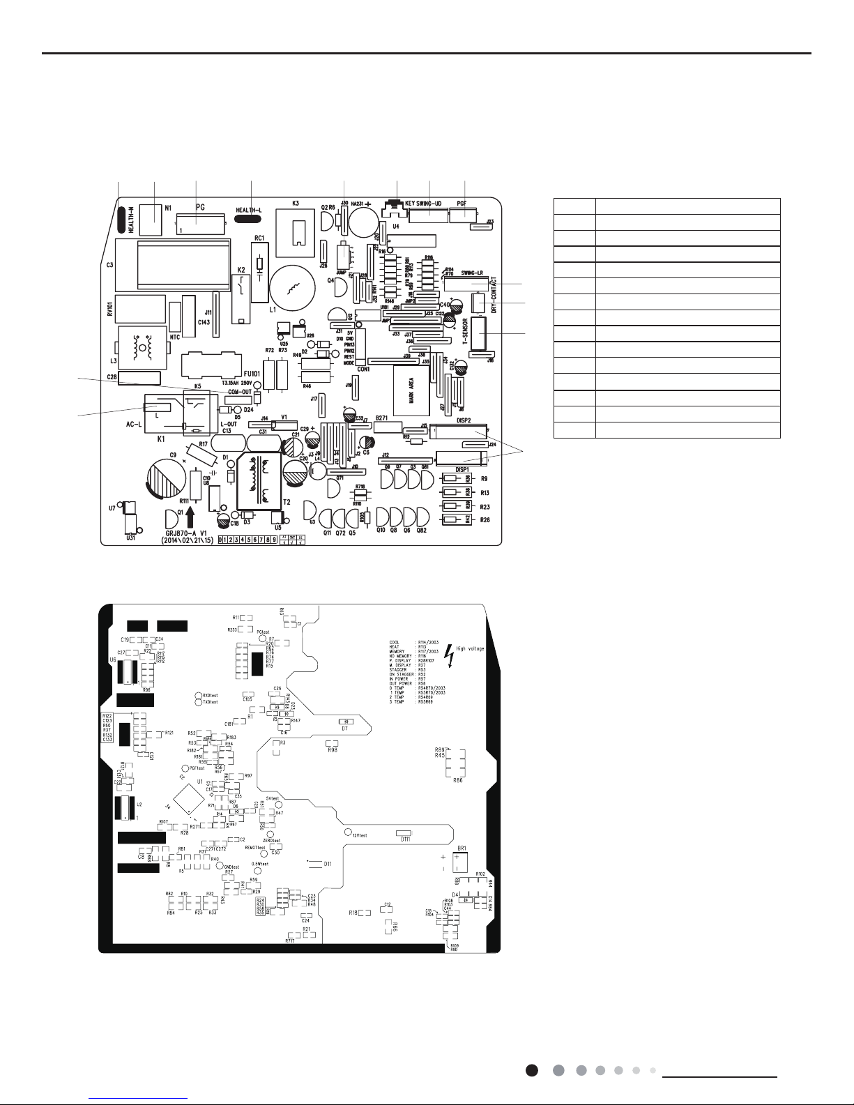
5.2 PCB Printed Diagram
Indoor Unit
● Top view
● Bottom view
No. Name
1 Interface of live wire
2 Communication interface
3 Interface of neutral wire for health
4 Interface of neutral wire
5 Control interface of motor
6 Interface of live wire for health
7 Jumper cap
8 Auto button
9 Interface for up&down swing
10 Feedback interface of motor
11
Interface of left&right swing
12 Interface of dry contact
13 Interface of temperature senso
14 Display interface
19
Technical Information
Service Manual
1
2
3
4
5
6
7
8
9
10
11
12131415
● Top view
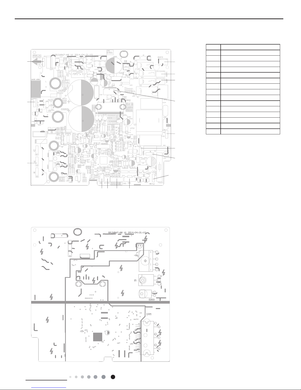
Outdoor Unit
● Bottom view
No. Name
1 Compressor
2 Reactor 2
3 Reactor 1
4 Chassis electric heating
5 Compressor electric heating
6 4-way valve
7 DC fan
8 Earthing wire
9
Communication wire
10 Neutral wire
11 Live wire
12 Electronic expansion valve
13 Temperature sensor
14 Overloard
15 DRED
20
Technical Information
Service Manual
6. Function and Control
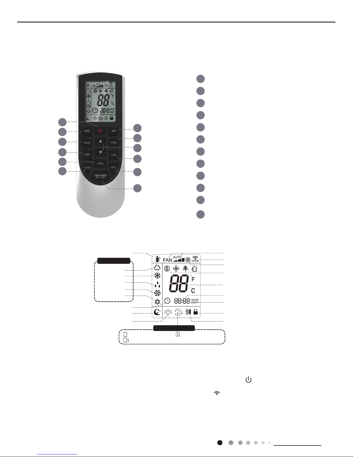
6.1 Remote Controller Introduction
Introduction for icons on display screen
Introduction for buttons on remote controller
1
5
3
6
8
10
12
11
9
7
4
2
1
2
3
4
5
6
7
8
9
10
11
12
ON/OFF button
MODE button
FAN button
SWING button
TURBO button
TEMP button
I FEEL button
LIGHT button
CLOCK button
TIMER ON / TIMER OFF
button
SLEEP button
▲/ button
▲
Send signal
Turbo mode
8
℃
heating function
Set temperature
Set time
TIMER ON / TIMER OFF
Child lock
Up & down swing
Set fan speed
Light
Temp. display type
:Set temp.
:Outdoor ambient temp.
:Indoor ambient temp.
Sleep mode
Clock
Heat mode
Fan mode
Dry mode
Cool mode
Auto mode
Operation mode
I feel
Note:
● After putting through the power, the air conditioner will give out a sound. Operation indictor " " is ON (red indicator). After that,
you can operate the air conditioner by using remote controller.
●
Under on status, pressing the button on the remote controller, the signal icon " "
on the display of remote controller will blink once
and the air conditioner will give out a “de” sound, which means the signal has been sent to the air conditioner.
● Under off status, set temperature and clock icon will be displayed on the display
of remote controller (If timer on, timer off and light functions are set, the corre- sponding icons will be displayed on the display of
remote controller at the same
time); Under on status, the display will show the corresponding set function icons.
21
Technical Information
Service Manual
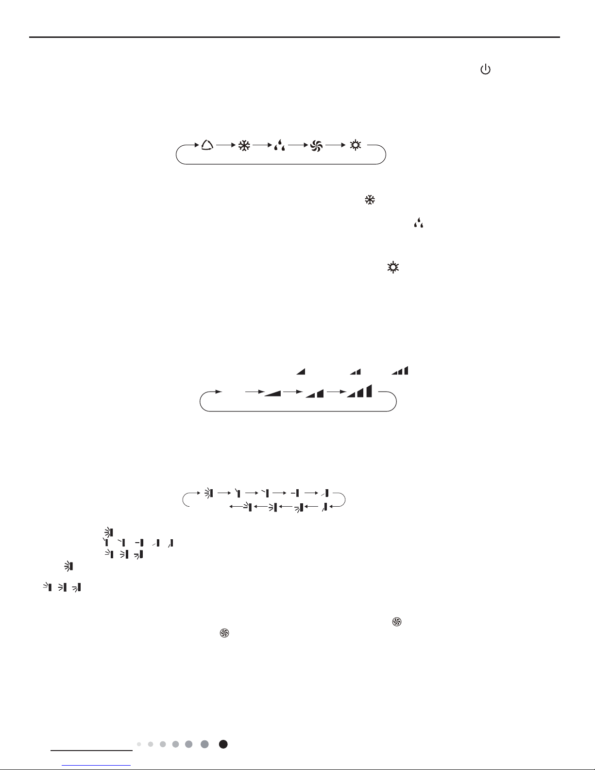
1. ON/OFF button
2. MODE button
3. FAN button
Press this button can turn on or turn off the air conditioner. After turning on the air conditioner, operation indicator " "on indoor unit’s
display is ON (green indicator. The colour is different for different models), and indoor unit will give out a sound.
● When selecting auto mode, air conditioner will operate automatically according to ex-factory setting. Set temperature can’t be adjusted and
will not be displayed as well. Press "FAN" button can adjust fan speed. Press "SWING" button can adjust fan blowing angle.
● After selecting cool mode, air conditioner will operate under cool mode. Cool indicator " "on indoor unit is ON. Press "▲" or " ▲ " button
to adjust set temperature. Press "FAN" button to adjust fan speed. Press "SWING" button to adjust fan blowing angle.
● When selecting dry mode, the air conditioner operates at low speed under dry mode. Dry indicator " " on indoor unit is ON. Under dry
mode, fan speed can’t be adjusted. Press "SWING" button to adjust fan blowing angle.
● When selecting fan mode, the air conditioner will only blow fan, no cooling and no heating. All indicators are OFF. Press "FAN" button to
adjust fan speed. Press "SWING" button to adjust fan blowing angle.
● When selecting heating mode, the air conditioner operates under heat mode. Heat indicator " " on indoor unit is ON. Press "▲" or " ▲ "
button to adjust set temperature. Press "FAN" button to adjust fan speed. Press "SWING" button to adjust fan blowing angle. (Cooling only
unit won’t receive heating mode signal. If setting heat mode with remote controller, press ON/OFF button can’t start up the unit).
Note:
● For preventing cold air, after starting up heating mode, indoor unit will delay 1~5 minutes to blow air (actual delay time is depend on indoor
ambient temperature).
● Set temperature range from remote controller: 16~30
O
C; Fan speed: auto, low speed, medium speed, high speed.
5. TURBO button
Under COOL or HEAT mode, press this button to turn to quick COOL or quick HEAT mode. " " icon is displayed on remote controller.
Press this button again to exit turbo function and " " icon will disappear.
6. ▲/
▲
button
● Press "▲" or "▲" button once increase or decrease set temperature 1
O
C. Holding "▲" or "
▲
" button, 2s later, set temperature on remote
controller will change quickly. On releasing button after setting is nished, temperature indicator on indoor unit will change accordingly.
(Temperature can’t be adjusted under auto mode)
● When setting TIMER ON, TIMER OFF or CLOCK, press "▲" or "▲" button to adjust time. (Refer to CLOCK, TIMER ON, TIMER OFF
buttons) When setting TIMER ON, TIMER OFF or CLOCK, press "▲" or "▲" button to adjust time. (Refer to CLOCK, TIMER ON, TIMER
OFF buttons)
Caution:
● Under AUTO speed, air conditioner will select proper fan speed automatically according to ex-factory setting.
● Fan speed under dry mode is low speed.
Pressing this button can set fan speed circularly as: auto (AUTO), low( ) ,medium( ), high( ).
Press this button to select your required operation mode.
AUTO COOL FAN
DRY HEAT
Auto
4. SWING button
Press this button can select up&down swing angle. Fan blow angle can be selected circularly as below:
● When selecting " ", air conditioner is blowing fan automatically. Horizontal louver will automatically swing up & down at maximum angle.
● When selecting "
、
、 、
、
", air conditioner is blowing fan at xed position. Horizontal louver will stop at the xed position.
● When selecting "
、
、
" , air conditioner is blowing fan at xed angle. Horizontal louver will send air at the xed angle.
● Hold " "button above 2s to set your required swing angle. When reaching your required angle, release the button.
Note:
● "
、
、
" may not be available. When air conditioner receives this signal, the air conditioner will blow fan automatically.
no display
(horizontal louvers stops at current position)
22
Technical Information
Service Manual
7. SLEEP button
9. I FEEL button
10. LIGHT button
11. CLOCK button
12. TIMER ON / TIMER OFF button
Under COOL, HEAT or DRY mode, press this button to start up sleep function. " " icon is displayed on remote controller. Press this button
again to cancel sleep function and " " icon will disappear.
Press this button to start I FEEL function and " " will be displayed on the remote controller. After this function is set, the remote controller
will send the detected ambient temperature to the controller and the unit will automatically adjust the indoor temperature according to the
detected temperature. Press this button again to close I FEEL function and " " will disappear.
● Please put the remote controller near user when this function is set. Do not put the remote controller near the object of high temperature
or low temperature in order to avoid detecting inaccurate ambient temperature.
Press this button to turn off display light on indoor unit. " " icon on remote controller disappears. Press this button again to turn on
display light. " " icon is displayed.
Press this button to set clock time. " " icon on remote controller will blink. Press "▲" or "▲" button within 5s to set clock time. Each
pressing of "▲" or "▲" button, clock time will increase or decrease 1 minute. If hold "▲" or "▲" button, 2s later, time will change quickly.
Release this button when reaching your required time. Press "CLOCK" button to conrm the time. " " icon stops blinking.
Note:
● Clock time adopts 24-hour mode.
● The interval between two operation can’t exceeds 5s. Otherwise, remote controller will quit setting status. Operation for TIMER ON/TIMER
OFF is the same.
● TIMER ON button
"TIMER ON" button can set the time for timer on. After pressing this button, " " icon disappears and the word "ON" on remote controller
blinks. Press "▲" or "▲"button to adjust TIMER ON setting. After each pressing "▲" or "▲" button, TIMER ON setting will increase or
decrease 1min. Hold "▲" or "▲" button, 2s later, the time will change quickly until reaching your required time. Press "TIMER ON" to
conrm it. The word "ON" will stop blinking. " " icon resumes displaying. Cancel TIMER ON: Under the condition that TIMER ON is
started up, press "TIMER ON" button to cancel it.
● TIMER OFF button
"TIMER OFF" button can set the time for timer off. After pressing this button," " icon disappears and the word "OFF" on remote
controller blinks. Press "▲" or "▲" button to adjust TIMER OFF setting. After each pressing "▲" or "▲" button,
TIMER OFF setting will increase or decrease 1min. Hold "▲" or "▲" button, 2s later, the time will change quickly until reaching your
required time. Press "TIMER OFF" word "OFF" will stop blinking. " " icon resumes displaying. Cancel TIMER OFF. Under the condition
that TIMER OFF is started up, press "TIMER OFF" button to cancel it.
Note:
● Under on and off status, you can set TIMER OFF or TIMER ON simultaneously.
● Before setting TIMER ON or TIMER OFF, please adjust the clock time.
● After starting up TIMER ON or TIMER OFF, set the constant circulating valid. After that, air conditioner will be turned on or turned off
according to setting time. ON/OFF button has no effect on setting. If you don’t need this function, please use remote controller to cancel it.
8. TEMP button
By pressing this button, you can see indoor set temperature, indoor ambient temperature or outdoor ambient temperature on indoor unit’s
display. The setting on remote controlleris selected circularly as below:
● When selecting " " or no display with remote controller, temperature indicator on indoor unit displays set temperature.
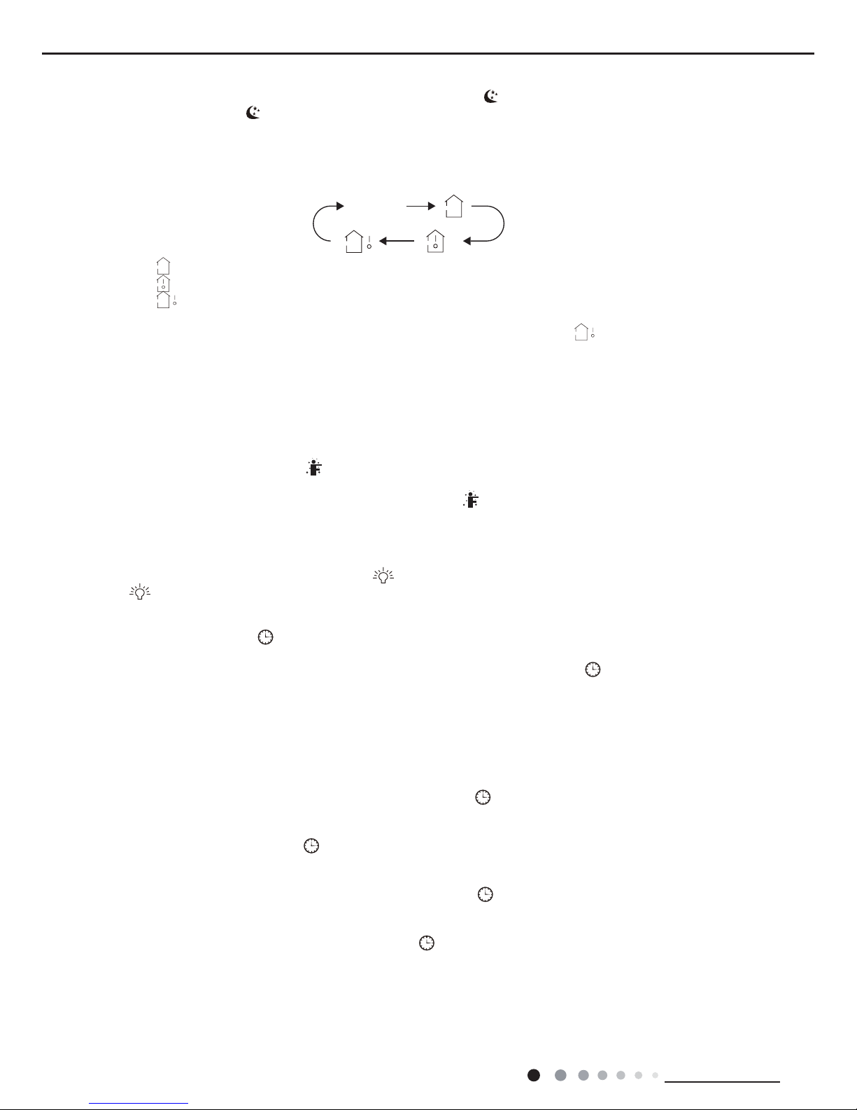
● When selecting " " with remote controller, temperature indicator on indoor unit displays indoor ambient temperature.
● When selecting " " with remote controller, temperature indicator on indoor unit displays outdoor ambient temperature.
Note:
●
Outdoor temperature display is not available for some models. At that time, indoor
unit receives " "signal, while it displays indoor set
temperature.
● It’s defaulted to display set temperature when turning on the unit.There is no display in the remote controller.
● Only for the models whose indoor unit has dual-8 display.
● When selecting displaying of indoor or outdoor ambient temperature, indoor temperature indicator displays corresponding temperature and
automatically turn to display set temperature after three or ve seconds.
no display
23
Technical Information
Service Manual
Function introduction for combination buttons
Operation guide
Replacement of batteries in remote controller
1. Energy-saving function
1. After putting through the power, press "ON/OFF" button on remote controller to turn on the air conditioner.
2. Press "MODE" button to select your required mode: AUTO, COOL, DRY, FAN, HEAT.
3. Press "▲" or "▲" button to set your required temperature. (Temperature can’t be adjusted under auto mode).
4. Press "FAN" button to set your required fan speed: auto, low, medium and high speed.
5. Press "SWING" button to select fan blowing angle.
● During operation, point the remote control signal sender at the receiving window on indoor unit.
● The distance between signal sender and receiving window should be no more than 8m, and there should be no obstacles between them.
● Signal may be interfered easily in the room where there is uorescent lamp or wireless telephone; remote controller should be close to
indoor unit during operation.
● Replace new batteries of the same model when replacement is required.
● When you don’t use remote controller for a long time, please take out the batteries.
● If the display on remote controller is fuzzy or there’s no display, please replace batteries.
2. 8 ℃ heating function
3. Child lock function
4. Temperature display switchover function
Under cooling mode, press "TEMP" and " CLOCK" buttons simultaneously to start up or turn off energy-saving function. When energy-saving
function is started up, "SE" will be shown on remote controller, and air conditioner will adjust the set temperature automatically according to
ex-factory setting to reach to the best energy-saving effect. Press "TEMP" and "CLOCK"buttons simultaneously again to exit energy-saving
function.
Note:
● Under energy-saving function, fan speed is defaulted at auto speed and it can’t be adjusted.
●
Under energy-saving function, set temperature can’t be adjusted. Press "TURBO"
button and the remote controller won’t send signal.
● Sleep function and energy-saving function can’t operate at the same time. If energy-saving function has been set under cooling mode,
press sleep button will cancel energy-saving function. If sleep function has been set under cooling mode, start up the energy-saving
function will cancel sleep function.
Under heating mode, press "TEMP" and "CLOCK" buttons simultaneously to start
up or turn off 8
O
C
heating function. When this function is
started up, " " and "8
O
C"
will be shown on remote controller, and the air conditioner keep the heating status
at 8OC. Press "TEMP" and
"CLOCK" buttons simultaneously again to exit 8℃heating function.
Note:
● Under 8
O
C heating function, fan speed is defaulted at auto speed and it can’t be adjusted.
● Under 8
O
C heating function, set temperature can’t be adjusted. Press "TURBO
"
button and the remote controller won’t send signal.
● Sleep function and 8
O
C heating function can’t operate at the same time. If 8OC heating function has been set under cooling mode, press
sleep button will cancel 8
O
C heating function. If sleep function has been set under cooling mode, start up the 8
℃
heating function will
cancel sleep function.
● Under OF temperature display, the remote controller will display 46OF heating.
Press "▲" and "▲" simultaneously to turn on or turn off child lock function. When child lock function is on, " " icon is displayed on remote
controller. If you operate the remote controller, the " " icon will blink three times without sending signal to the unit.
Under OFF status, press "▲" and "MODE" buttons simultaneously to switch temperature display between
℃
and ℉.
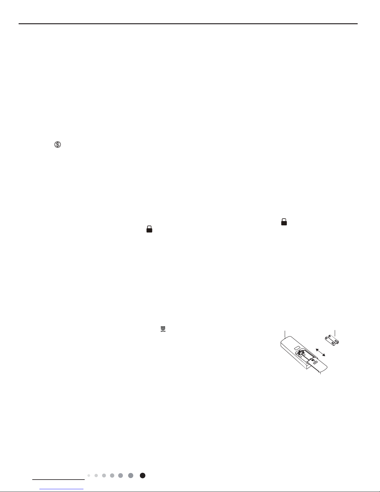
1. Press the back side of remote controller marked with " ", as shown in the g, and then push
out
the cover of battery box along the arrow direction.
2. Replace two 7# (AAA 1.5V) dry batteries, and make sure the position of "+" polar and "-" polar
are correct.
3. Reinstall the cover of battery box.
Note:
signal sender battery
Cover of battery box
remove
reinstall

24
Technical Information
Service Manual
6.2 Brief Description of Modes and Functions
1.Basic function of system
(1)Cooling mode
(1) Under this mode, fan and swing operates at setting status. Temperature setting range is 16~30
O
C.
(2) During malfunction of outdoor unit or the unit is stopped because of protection, indoor unit keeps original operation status.
(2)Drying mode
(1) Under this mode, fan operates at low speed and swing operates at setting status. Temperature setting range is 16~30
O
C.
(2) During malfunction of outdoor unit or the unit is stopped because of protection, indoor unit keeps original operation status.
(3) Protection status is same as that under cooling mode.
(4) Sleep function is not available for drying mode.
(3)Heating mode
(1) Under this mode, Temperature setting range is 16~30
O
C.
(2) Working condition and process for heating mode:
When turn on the unit under heating mode, indoor unit enters into cold air prevention status. When the unit is stopped or at OFF status,
and indoor unit has been started up just now, the unit enters into residual heat-blowing status.
(4)Working method for AUTO mode:
1.Working condition and process for AUTO mode:
a.Under AUTO mode, standard heating Tpreset=20OC and standard cooling Tpreset=25OC. The unit will switch mode automatically
according to ambient temperature.
2.Protection function
a. During cooling operation, protection function is same as that under cooling mode.
b. During heating operation, protection function is same as that under heating mode.
3. Display: Set temperature is the set value under each condition. Ambient temperature is (Tamb.-Tcompensation) for heat pump unit
and Tamb. for cooling only unit.
4. If there’s I feel function, Tcompensation is 0. Others are same as above.
(5)Fan mode
Under this mode, indoor fan operates at set fan speed. Compressor, outdoor fan, 4-way valve and electric heating tube stop operation.
Indoor fan can select to operate at high, medium, low or auto fan speed. Temperature setting range is 16~30
O
C.
2. Other control
(1) Buzzer
Upon energization or availably operating the unit or remote controller, the buzzer will give out a beep.
(2) Auto button
If press this auto button when turning off the unit, the complete unit will operate at auto mode. Indoor fan operates at auto fan speed
and swing function is turned on. Press this auto button at ON status to turn off the unit.
(3) Auto fan
Heating mode: During auto heating mode or normal heating ode, auto fan speed will adjust the fan speed automatically according to
ambient temperature and set temperature.
(4) Sleep
After setting sleep function for a period of time, system will adjust set temperature automatically.
(5) Timer function:
General timer and clock timer functions are compatible by equipping remote controller with different functions.
(6) Memory function
memorize compensation temperature, off-peak energization value.
Memory content: mode, up&down swing, light, set temperature, set fan speed, general timer (clock timer can’t be memorized).
After power recovery, the unit will be turned on automatically according to memory content.
(7) Health function
During operation of indoor fan, set health function by remote controller. Turn off the unit will also turn off health function.
Turn on the unit by pressing auto button, and the health is defaulted ON.
●
Indoor Unit

25
Technical Information
Service Manual
(8)I feel control mode
After controller received I feel control signal and ambient temperature sent by remote controller, controller will work according to the ambient
temperature sent by remote controller.
(9)Entry condition for compulsory defrosting function
When turn on the unit under heating ode and set temperature is 16
O
C (or 16.5
O
C by remote controller), press “+, -, +, -, +, -” button
successively within 5s and then indoor unit will enter into compulsory defrosting setting status:
(1) If there’s only indoor unit’s controller, it enters into indoor normal defrosting mode.
(2) If there’s indoor unit’s controller and outdoor unit’s controller, indoor unit will send compulsory defrosting mode signal to outdoor unit and
then outdoor unit will operate under normal defrosting mode. After indoor unit received the signal that outdoor unit has entered into defrosting
status, indoor unit will cancel to send compulsory mode to outdoor unit. If outdoor unit hasn’t received feedback signal from outdoor unit after
3min, indoor unit will also cancel to send compulsory defrosting signal.
(10)Refrigerant recovery function:
Enter into Freon recovery mode actively: Within 5min after energization, turn on the unit at 16OC under cooling mode, and press light button
for 3 times within 3s to enter into Freon recovery mode. Fo is displayed and Freon recovery mode will be sent to outdoor unit.
(11)Ambient temperature display control mode
1. When user set the remote controller to display set temperature (corresponding remote control code: 01), current set temperature will be
displayed.
2. Only when remote control signal is switched to indoor ambient temperature display status (corresponding remote control code: 10) from
other display status (corresponding remote control code: 00, 01,11),controller will display indoor ambient temperature for 3s and then turn
back to display set temperature.
Under this mode, indoor fan operates at set fan speed. Compressor, outdoor fan, 4-way valve and electric heating tube stop operation.
Indoor fan can select to operate at high, medium, low or auto fan speed. Temperature setting range is 16~30
O
C.
(12)Off-peak energization function:
Adjust compressor’s minimum stop time. The original minimum stop time is 180s and then we change to:
The time interval between two start-ups of compressor can’t be less than 180+Ts(0≤T≤15). T is the variable of controller. That’s to say
the minimum stop time of compressor is 180s~195s. Read-in T into memory chip when refurbish the memory chip each time. After power
recovery, compressor can only be started up after 180+T s at least.
(13) SE control mode
The unit operates at SE status.
(14) X-fan mode
When X-fan function is turned on, after turn off the unit, indoor fan will still operate at low speed for 2min and then the complete unit will be
turned off. When x-fan function is turned off, after turn off the unit, the complete unit will be turned off directly.
(15) 8º heating function
Under heating mode, you can set 8º heating function by remote controller. The system will operate at 8ºset temperature.
(16)Turbo function
Turbo function can be set under cooling and heating modes. Press Fan Speed button to cancel turbo setting. Turbo function is not available
under auto, drying and fan modes.

26
Technical Information
Service Manual
1. Cooling mode:
Working condition and process of cooling mode:
①
When Tindoor ambient temperature≥Tpreset, unit enters into cooling mode. Indoor fan, outdoor fan and compressor
start operation. Indoor fan operates according to set fan speed.
②
When Tindoor ambient temperature≤Tpreset-2℃, compressor stops operation and outdoor fan will stop 30s later.
Indoor fan operates according to set fan speed.
③
When Tpreset-2℃<Tindoor ambient temperature<Tpreset, unit operates according to the previous status.
Under cooling mode, 4-way valve is not energized. Temperature setting range is 16~30℃. If compressor stops because of
malfunction in cooling mode, indoor fan and swing motor will work according to the original status.
2. Drying mode
(1) Working condition and process of drying mode
①
When Tindoor ambient temperature>Tpreset, unit will be in drying mode. Outdoor fan and compressor start operation
while indoor fan will operate at low fan speed.
②
When Tpreset-2℃≤Tindoor ambient temperature≤Tpreset, unit operates according to the previous status.
③
When Tindoor ambient temperature
<
Tpreset-2
℃
, compressor stops operation and outdoor fan will stop 30s later.
(2) Under drying mode, 4-way valve is not energized. Temperature setting range is 16~30
℃
.
(3) Protection function: same as in cooling mode.
3. Fan mode
(1) Under this mode, indoor fan can select different fan speed (except Turbo) or auto fan speed. Compressor, outdoor fan
and 4-way valve all stop operation.
(2) In fan mode, temperature setting range is 16~30
℃
.
4. Heating mode
Working condition and process of heating mode:
①
When Tpreset-(Tindoor ambient temperature-Tcompensation)≥1℃, unit enters into heating mode. Compressor,
outdoor fan and 4-way valve start operation.
②
When -2℃<Tpreset-(Tindoor ambient temperature-Tcompensation)
<1℃
, unit operates according to the previous
status.
③
When Tpreset-(Tindoor ambient temperature-Tcompensation)≤-2℃, compressor stops operation and outdoor fan
will stop 30s later. Indoor fan will be in residual-heat blowing status.
④
When unit is turned off under heating mode or changed to other modes from heating mode, 4-way valve will be
power-off 2min after compressor stops working (compressor is in operation status under heating mode).
⑤
When Toutdoor ambient temperature
>30℃
, compressor stops operation immediately. Outdoor fan will stop 30s later.
⑥
Under the condition that compressor is turned on, when unit is changed to heating mode from cooling or drying mode,
4-way valve will be energized in 2~3min’s delay.
Note: Tcompensation is determined by IDU and ODU. If IDU controls the compensation temperature, then Tcompensation is
determined according to the value sent by IDU to ODU; If IDU does not control the compensation temperature, then
Tcompensation will default to 3℃ by the ODU.
5. Freon recovery mode
After the Freon recovery signal from IDU is received, cooling at rated frequency will be forcibly turned on to recover Freon.
Indoor unit will display Fo. If any signal from remote controller is received, unit will exit from Freon recovery mode and
indoor unit stops displaying Fo.
6. Compulsory defrosting
If unit is turned on under heating mode and set temperature is 16℃ (by remote controller), press “+, -, +, -, +, -” within
5s, unit will enter into compulsory defrosting mode and send the signal to ODU. When the compulsory defrosting signal from
ODU is received, IDU will exit from the compulsory defrosting mode and stop sending the signal to ODU.
After ODU receives the compulsory defrosting code, it will start compulsory defrosting. Defrosting frequency and opening
angle will be the same as in normal defrosting mode. When compulsory defrosting is nished, the complete unit resumes
original status.
●
Outdoor Unit
 Loading...