

Gree GWH09QB-D3DNA6E, GWC18QD-D3DNA6E, GWH18QD-D3DNA6E, GWC24QE-D3DNA6E, GWH24QE-D3DNA6E Owner's Manual
...
OWNER’S MANUAL
Thank you for choosing our product. Please read this owner’s manual carefully
before operating the unit and keep it for future reference.
GWC09QB-D3DNA6E
GWH09QB-D3DNA6E
GWC12QC-D3DNA6E
GWH12QC-D3DNA6E
GWC18QD-D3DNA6E
GWH18QD-D3DNA6E
GWC24QE-D3DNA6E
GWH24QE-D3DNA6E

Content
Operation Notices
Precautions ..............................................................................1
Parts Name ..............................................................................5
Indoor Unit Screen Display ......................................................6
Remote Control
Buttons on remote control ........................................................7
Introduction for icons on remote control ..................................8
Operation of remote control ......................................................9
Special functions ......................................................................12
Replacement of batteries in remote controller ........................13
Emergency operation ..............................................................14
Maintenance
Clean and Maintenance ..........................................................15
Malfunct
ion
M
alfunction analysis ................................................................17
Installation Notice
Installation dimension diagram ................................................21
Tools for installation ................................................................22
Selection of installation location ..............................................22
Requirements for electric connection ......................................23
Installation
Installation of indoor unit ..........................................................24
Installation of outdoor unit ........................................................29
Vacuum pumping ....................................................................32
Leakage detection ....................................................................32
Check after installation ............................................................33
Test and operation
Test operation ..........................................................................33
Attachment
Configura
tion of connection pipe ...
.........................................34
Pipe expanding method ..........................................................36
Wired Controller ......................................................................37
This appliance is not intended for use by persons (including children) with
reduced physical, sensory or mental capabilities, or lack of experience and
knowledge, unless they have been given supervision or instruction
concerning use of the appliance by a person responsible for their safety.
Children should be supervised to ensure
that they do not play with the
a
ppliance.
ANGLAIS
1A
Precautions
WARNING
Operation and Maintenance
• This appliance can be used by children aged from 8 years and above
and persons with reduced physical, sensory or mental capabilities or
lack of experience and knowledge if they have been given supervision or instruction concerning use of the appliance in a safe
way and understand the hazards involved.
• Children shall not play with the appliance.
• Cleaning and user maintenance shall not be made by
children.
• Do not connect air conditioner to multi-purpose socket.
Otherwise, it may cause fire hazard.
• Do disconnect power supply when cleaning air
conditioner. Otherwise, it may cause electric shock.
• If the supply wire is damaged, it must be replaced by
the manufacturer, its service agent or similarly qualified
persons in order to avoid a hazard.
• Do not wash the air conditioner with water to avoid
e
lectric shock.
• Do not spray water on indoor unit. It may cause electric
shock or malfunction.
• After removing the filter, do not touch fins to avoid injury.
• Do not use fire or hair dryer to dry the filter to avoid
deformation or fire hazard.

2
Precautions
WARNING
Attachment
• Installation must be performed by qualified professionals.
Otherwise, it may cause personal injury or damage.
• Must follow the electric safety regulations when installing the unit.
• According to the local safety regulations, use qualified power supply
circuit and circuit break.
• Install a circuit breaker of adequate capacity only used for the
system; otherwise, it may cause malfunction.
• An all-pole disconnection switch having a contact separation of at
least 3mm in all poles should be connected in fixed wiring.
• Air Conditioner should be properly grounded. Incorrect grounding
may cause electric shock.
• Make sure the power supply matches with the requirement of air
conditioner.Unstable power supply or incorrect wiring may cause mal
function of the unit, electric shock or fire hazard
• Properly connect the live wire, neutral wire and grounding wire.
• Be sure to cut off the power supply before proceeding any work
related to electricity and safety.

4
Precautions
WARNING
• If you need to relocate the air conditioner to another place, only a
qualified person can perform the work. Otherwise, it may cause
personal injury or damage.
• Select a location which is out of reach for children and far away from
animals or plants.If it is unavoidable, please add the fence around the
outdoor unit for safety purpose.
• The indoor unit should be installed close to the wall.
• Instructions for installation and use of this product are provided by
the manufacturer.
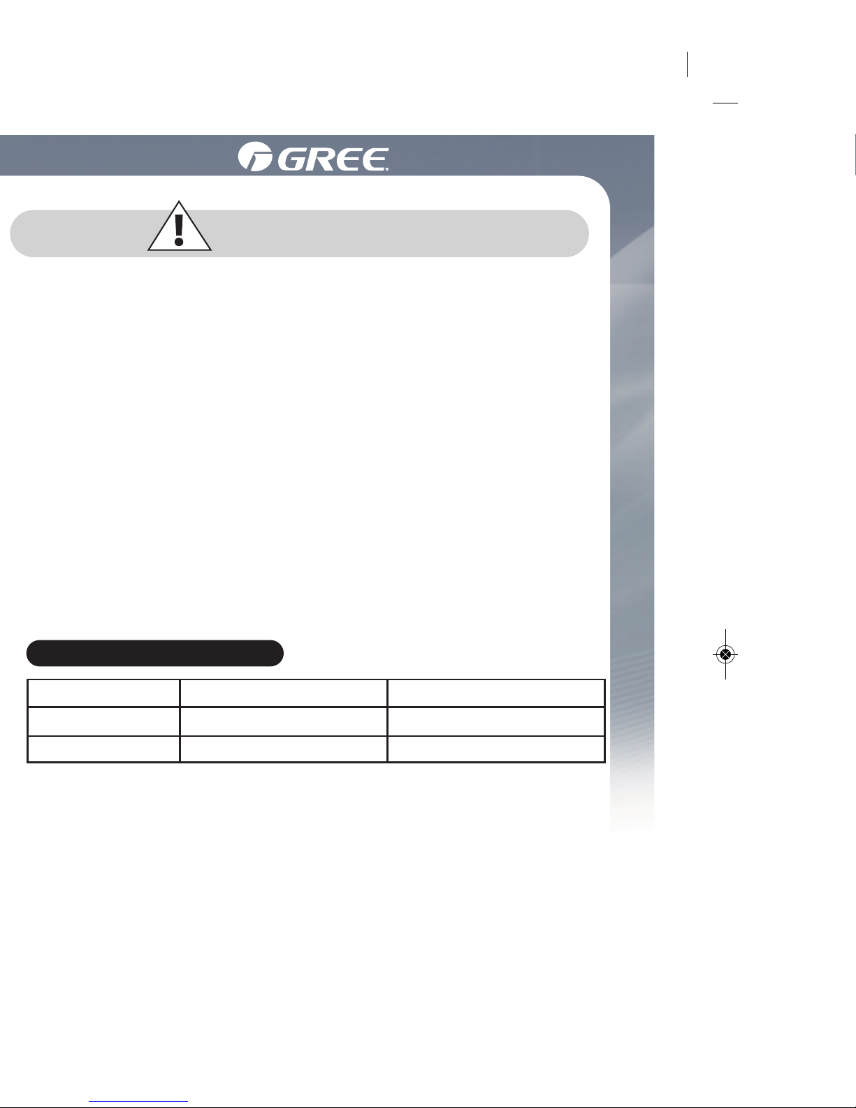
Working temperature range
Indoor side DB/WB(°C ) Outdoor side DB/WB(°C )
Maximum cooling
NOTICE :
• The operating temperature range (outdoor temperature) for cooling
only unit is -18 (-0.4°F)~46.1℃ (115°F) ; for heat pump unit is
-20℃ (-4°F)~46.1℃ (115°F).
26.7/19.4 (80/66.9) 46.1/23.9 (115/75)
26.7/- (80/-) 23.9/18.3 (75/64.9)
Maximum cooling

6
W R G
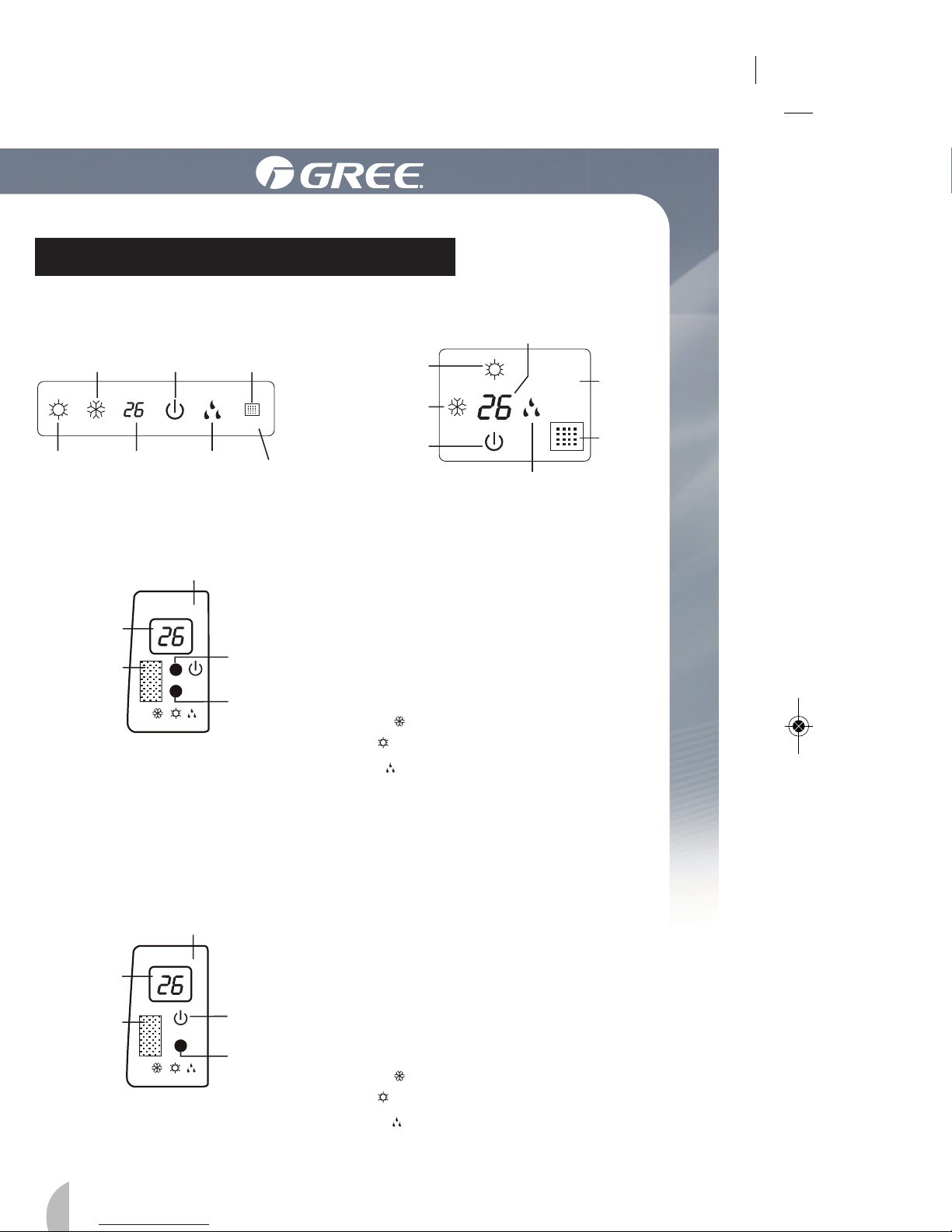
Indoor Unit Screen Display
For some model: For some model:
For some model:
cooling
indicator
power
indicator
receiver
window
receiver
window
heating
indicator
cooling
indicator
power
indicator
display
display
(only for heating mode)
receiver
window
drying
indicator
heating
indicator
temp.
indicator
temp.
indicator
Power LED color
indicator:
Green status ON:
Red status OFF:
Mode LED color indicator:
White W Cool Mode
Red R Heat Mode
Green G Dry Mode
d
rying
indicator
display
Display and icons position may vary with models
W
R
G
W R O
For some model:
receiver
window
display
(only for heating mode)
temp.
indicator
Power LED color indicator:
Green-status-ON.
Red -status-OFF.
Mode LED color indicator:
White W Cool Mode
Red R Heat Mode
Orange O Dry Mode
W
R
G
Display content or position may be different from above graphics,
please refer to actual products.

8
Using the Remote Control
1.2 Preparation before operation
Using the Remote Control
When using the remote control for the first time or after replacing the
batteries, please set the current time as per the following steps:
(1). Pressing CLOCK button, is blinking.
(2). Pressing or button, the clock time will increase or
decrease rapidly.
(3). Press CLOCK button again to confirm the time and return to
d
isplay current time.
(1). Selecting operation mode
In unit on status, press MODE button to select operation
mode in following sequence:
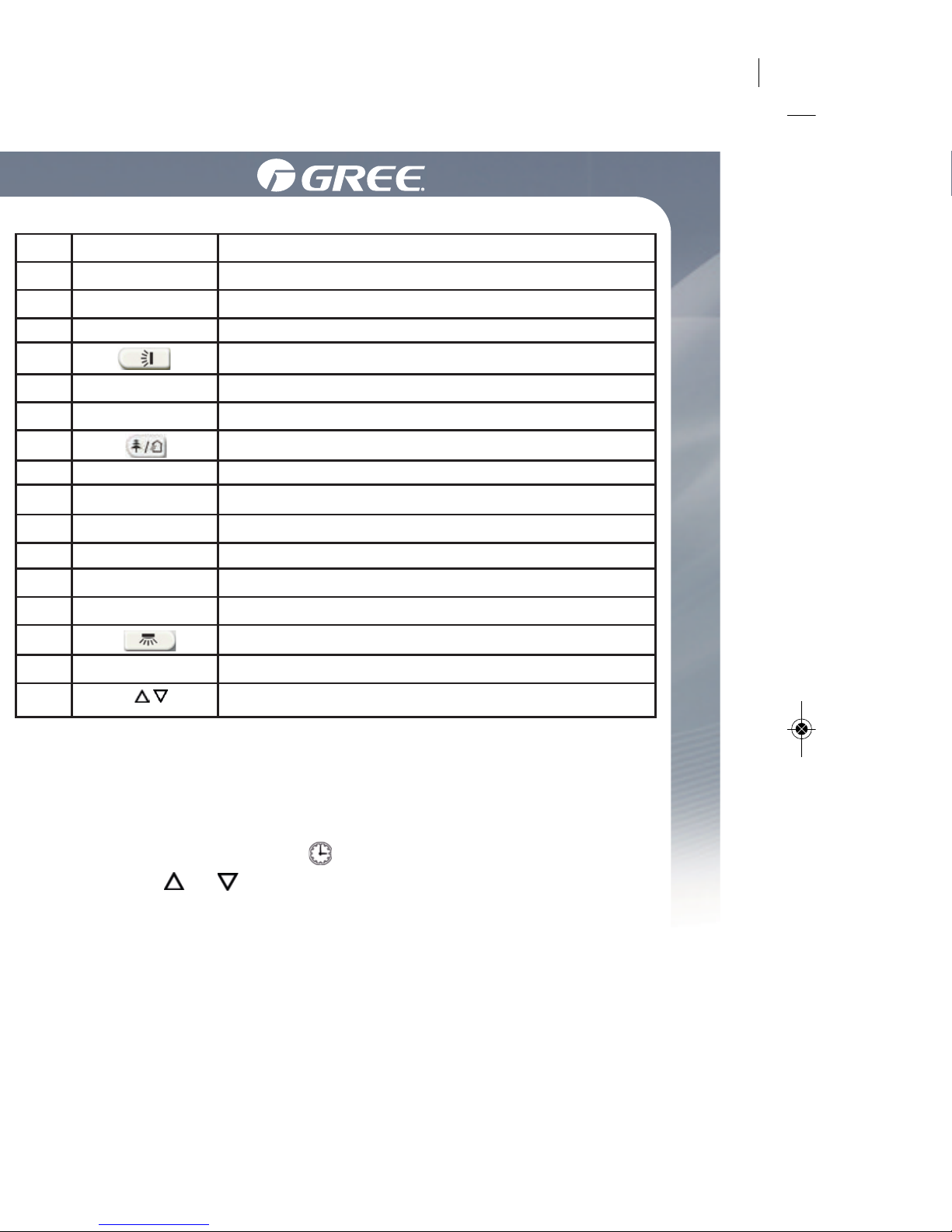
No.
1
2
3
4
5
6
7
8
9
10
11
12
13
14
15
16
Button name
ON/OFF
TURBO
MODE
I FEEL
TEMP
LIGHT
X-FAN
SLEEP
CLOCK
TOFF
TON
FAN
Function
Turn on or turn off the unit
Set turbo function
Set operation mode
Set up&down swing status
Set I FEEL function
Switch temperature displaying type on the unit’s display
Set health function and air function
Set light function
Set X-FAN function
Set sleep function
Set clock of the system
Set timer off function
Set timer on function
Set left&right swing status
Set fan speed
Set temperature and time
/
o

10
Using the Remote Control
Under cool or heat mode, press TURBO button to set turbo function.
When is displayed, turbo function is on. When it is not displayed,
turbo function is off.
When turbo function is on, the unit operates in super high speed to
achieve quick cooling or heating. When turbo function is off, the unit
operates in setting fan speed.
The light on the receiver light board will display present operation
s
tatus. If you want to turn off the light, please press LIGHT button.
Press this button again to turn on the light.
In unit on status, receiver light board is defaulted to display setting
temperature. Press TEMP button to view indoor or outdoor ambient
temperature.
Health function is available when the unit is equipped with anion
generator. When health function is on, the anion generator will start
o
peration, absorbing the dusts and killing the bacteria in the room.
(5). Setting turbo function
(6). Setting light function
(7). Viewing ambient temperature
(8). Setting X-FAN function
In cool or dry mode, press X-FAN button to set X-FAN function.
When is displayed, X-FAN function is on. When you cancel
the function by pressing again the button, the icon will disappear.
When X-FAN function is on, after you have pressed the ON/OFF
(
marche/arrêt) button to stop the unit, the fan will keep un running for about 2 min. to blow away the water on the evaporator,
thus eliminating risk of mildew.
(9). Setting health function
In unit on status, press button to set health function.
When is displayed, health function is on.
When you cancel the HEALTH mode by pressing again on
the button, the icon will disappear.
W
hen is displayed, the set in temperature is displayed.
When is displayed, the indoor ambient temperature is
displayed.
When is displayed, the current outdoor temperature is
displayed.
Note: set in temperature is always displayed in Remote Controller.

12
Using the Remote control
1.4 Special function buttons
④. Press TOFF button again to cancel timer and OFF is not displayed.
2). Setting timer on
① . Pressing TON button, “ON” is blinking and time displaying zone
displays the timer time of last setting.
②. Press or button to adjust the timer time.
③. Press TON button again to confirm setting. ON is displayed and time
displaying zone resumes to display current time.
④
. Press TON button again to cancel timer and ON is not displayed.
(1). Setting child lock
Press and buttons simultaneously to lock the buttons on
remote control and is displayed .
Press and buttons simultaneously again to unlock the buttons
on remote control and is not displayed .
If the buttons are locked, blinks 3 times when pressing the button
and any operation on the button is invalid.
(
2). Switching temperature scale
In unit off status, press MODE button and button simultaneously
to switch temperature scale between ℃ and ℉.
(3). Setting energy-saving function
In unit on status and under cool mode, press CLOCK and TEMP
buttons simultaneously to enter energy-saving mode.
u When is displayed, energy-saving function is on.
u When is not displayed, energy-saving function is off.
If you want to turn off the energy-saving function, press again on
CLOCK and TEMP buttons and is no longer displayed.
Note: energy-saving function is only available in cooling mode and it will
be exited when switching mode or setting sleep function.
(4). Absence function
In unit on status and under heat mode, press CLOCK and TEMP buttons
simultaneously to enter absence function. Temperature displaying zone
displays 8 and is displayed.
Press CLOCK and TEMP buttons simultaneously again to exit absence
 Loading...