

Gree GWH12QB-K6DNA5I, GWH12QB-K6DNA1I, GWH12QB-K6DNB4I, GWH12QB-K6DNB2I, GWH12QB-K6DNA3I Service Manual
...
Service Manual
Change for life
GREE ELECTRIC APPLIANCES, INC. OF ZHUHAI
GWH12QB-K6DNB8I
GWH12QB-K6DNB2I
GWH12QB-K6DNB4I
GWH12QB-K6DNA1I
GWH12QB-K6DND6I
GWH12QB-K6DNA5I
GWH12QB-K6DND6I
GWH12QB-K6DNA3I
GWH12QB-K6DNC6I
GWH12QB-K6DNC4I
GWH12QB-K6DNC8I
(Refrigerant:R32)
Models:

Service Manual
Table of Contents
Table of Contents
Part
Ⅰ
: Technical Information
.......................................................................1
1. Summary
......................................................................................................................1
2. Specications
..........................................................................................................3
2.1 Specication Sheet ...........................................................................................................3
2.2 Operation Characteristic Curve ........................................................................................5
2.3 Capacity Variation Ratio According to Temperature .........................................................5
2.4 Cooling and Heating Data Sheet in Rated Frequency .....................................................6
2.5 Noise Curve ......................................................................................................................6
3. Outline Dimension Diagram
........................................................................7
3.1 Indoor Unit ........................................................................................................................7
3.2 Outdoor Unit .....................................................................................................................8
4. Refrigerant System Diagram
......................................................................9
5. Electrical Part
.........................................................................................................10
5.1 Wiring Diagram ...............................................................................................................10
5.2 PCB Printed Diagram .....................................................................................................14
6. Function and Control
......................................................................................17
6.1 Remote Controller Introduction of YAN1F6(WiFi) ...........................................................17
6.2 Remote Controller Introduction of YAP1FB2(WiFi) .......................................................22
6.3 Brief Description of Modes and Functions ......................................................................27
6.4 GREE+ App Operation Manual ......................................................................................32
6.5 Ewpe Smart App Operation Manual ...............................................................................33
Part
Ⅱ
: Installation and Maintenance
.................................................34
7. Notes for Installation and Maintenance
..........................................34
8. Installation
................................................................................................................38
8.1 Installation Dimension Diagram ......................................................................................38
8.2 Installation Parts-checking ............................................................................................40
8.3 Selection of Installation Location ....................................................................................40
8.4 Requirements for electric connection .............................................................................40
8.5 Installation of Indoor Unit ................................................................................................40
8.6 Installation of Outdoor Unit .............................................................................................43
8.7 Vacuum Pumping and Leak Detection ...........................................................................44
8.8 Check after Installation and Test Operation ...................................................................44

Service Manual
9. Maintenance
............................................................................................................45
9.1 Malfunction Analysis .......................................................................................................45
9.2 Flashing LED of Indoor Unit/Outdoor and Primary Judgement ......................................49
9.3 How to Check Simply the Main Part ...............................................................................58
10. Exploded View and Parts List
..............................................................72
10.1 Indoor Unit ....................................................................................................................72
10.2 Outdoor Unit .................................................................................................................78
11. Removal Procedure
.......................................................................................80
11.1 Removal Procedure of Indoor Unit ...............................................................................80
11.2 Removal Procedure of Outdoor Unit ............................................................................85
Appendix:
........................................................................................................................89
Appendix 1: Reference Sheet of Celsius and Fahrenheit ....................................................89
Appendix 2: Conguration of Connection Pipe .....................................................................89
Appendix 3: Pipe Expanding Method ...................................................................................90
Appendix 4: List of Resistance for Temperature Sensor ......................................................91
1
Technical Information
Service Manual
1. Summary
Part
Ⅰ
: Technical Information
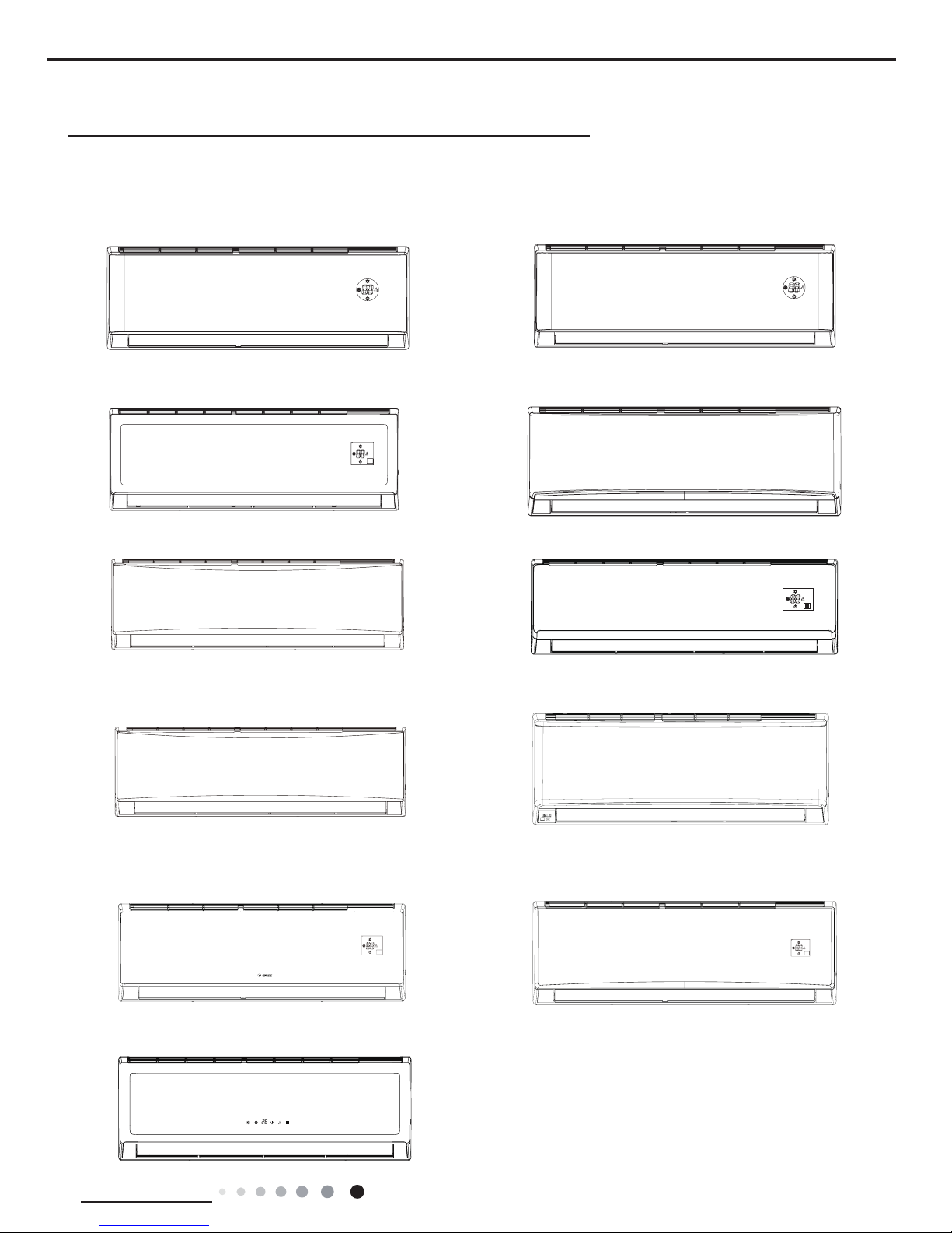
Indoor Unit:
GWH12QB-K6DNB8I/I GWH12QB-K6DNB2I
GWH12QB-K6DNB4I/I
GWH12QB-K6DND6I/I
GWH12QB-K6DNA5I/I
GWH12QB-K6DND6I/I
GWH12QB-K6DNC6I/I
GWH12QB-K6DNC8I/I
GWH12QB-K6DNA3I/I
GWH12QB-K6DNC4I/I
GWH12QB-K6DNA1I/I
2
Technical Information
Service Manual
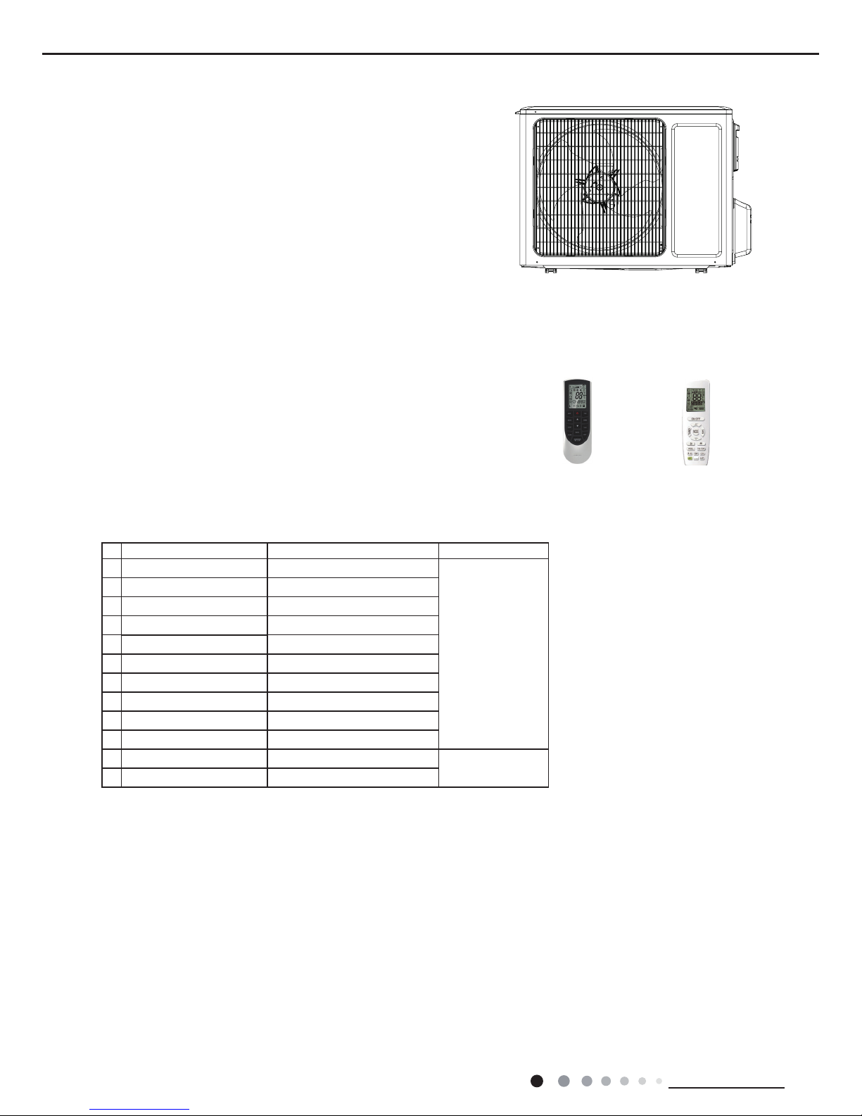
Remote Controller: YAN1F6(WiFi) YAP1FB2(WiFi)
Outdoor Unit:
GWH12QB-K6DNB8I/O
WiFi
No Model Product code Remote Controller
1 GWH12QB-K6DNB8I CB438006800/CB438006801
YAN1F6(WiFi)
2 GWH12QB-K6DNB2I CB432012300
3 GWH12QB-K6DNB4I CB434010600/CB434010601
4 GWH12QB-K6DNA1I CB419015000
5 GWH12QB-K6DND6I CB460005100
6 GWH12QB-K6DNA5I CB425011800
7 GWH12QB-K6DND6I CB460005101
8 GWH12QB-K6DNA3I CB424006500
9 GWH12QB-K6DNC8I CB456006200
10 GWH12QB-K6DNC6I CB443005400
11 GWH12QB-K6DNC4I CB444007501
YAP1FB2(WiFi)
12 GWH12QB-K6DNB8I CB438006802
Model List:
3
Technical Information
Service Manual
Model
1.GWH12QB-K6DNB8I 2.GWH12QB-K6DNB2I
3.GWH12QB-K6DNB4I 4.GWH12QB-K6DNA1I
5.GWH12QB-K6DND6I 6.GWH12QB-K6DNA5I
7.GWH12QB-K6DND6I 8.GWH12QB-K6DNA3I
9. GWH12QB-K6DNC6I 10.GWH12QB-K6DNC4I
11.GWH12QB-K6DNC8I 12.GWH12QB-K6DNB8I
Product Code
1.CB438006800/CB438006801 2.CB432012300
3.CB434010600/CB434010601 4.CB419015000
5.CB460005100 6.CB425011800 7.CB460005101
8.CB424006500 9CB443005400 10.CB444007501
11.CB456006200 12.CB438006802
Power
Supply
Rated Voltage V~ 220-240
Rated Frequency Hz 50
Phases 1
Power Supply Mode Outdoor
Cooling Capacity W 3200
Heating Capacity W 3500
Cooling Power Input W 997
Heating Power Input W 970
Cooling Current Input A 4.42
Heating Current Input A 4.30
Rated Input W 1500
Rated Current A 6.21
Air Flow Volume(SH/H/M/L/SL) m
3
/h 560/480/410/290/-
Dehumidifying Volume L/h 1.4
EER W/W 3.21
COP W/W 3.61
SEER 6.10
SCOP(Average/Warmer/Colder) 4.00
HSPF /
Application Area m
2
15-22
Indoor
Unit
Indoor Unit Model
1.GWH12QB-K6DNB8I/I 2.GWH12QB-K6DNB2I/I
3.GWH12QB-K6DNB4I/I 4.GWH12QB-K6DNA1I/I
5.GWH12QB-K6DND6I/I 6.GWH12QB-K6DNA5I/I
7.GWH12QB-K6DND6I/I 8.GWH12QB-K6DNA3I/I
9.GWH12QB-K6DNC6I/I 10.GWH12QB-K6DNC4I/I
11.GWH12QB-K6DNC8I 12.GWH12QB-K6DNB8I/I
Indoor Unit Product Code
1.CB438N06800/CB438N06801 2.CB432N12300
3.CB434N10600/CB434N10601 4.CB419N15000
5.CB460N05100 6.CB425N11800 7.CB460N05101
8.CB424N06500 9.CB443N05400 10.CB444N07501
11.CB456N06200 12.CB438N06802
Fan Type Cross-ow
Fan Diameter Length(DXL) mm Ф98X580
Cooling Speed(SH/H/M/L/SL) r/min 1350/1200/1050/750/Heating Speed(SH/H/M/L/SL) r/min 1350/1200/1050/850/Fan Motor Power Output W 20
Fan Motor RLA A 0.215
Fan Motor Capacitor μF 1
Evaporator Form Aluminum Fin-copper Tube
Evaporator Pipe Diameter mm Ф5
Evaporator Row-n Gap mm 2-1.4
Evaporator Coil Length(LXDXW) mm 584X22.8X266.7
Swing Motor Model MP24AA
Swing Motor Power Output W 1.5
Fuse Current A 3.15
Sound Pressure Level(SH/H/M/L/SL)dB (A) 41/37/33/25/-
Sound Power Level(SH/H/M/L/SL) dB (A) 55/47/43/35/Dimension(WXHXD) mm 790X275X200
Dimension of Carton Box(LXWXH) mm 863X268X352
Dimension of Package(LXWXH) mm 866X271X367
Net Weight kg 9
Gross Weight kg 11
2. Specications
2.1 Specication Sheet
4
Technical Information
Service Manual
Outdoor
Unit
Model of Outdoor Unit GWH12QB-K6DNB8I/O
Product Code of Outdoor Unit CB438W06800
Compressor Manufacturer/Trademark ZHUHAI LANDA COMPRESSOR CO., LTD
Compressor Model QXF-B096zE190A
Compressor Oil FW68DA
Compressor Type Rotary
L.R.A. A 20.0
Compressor RLA A 4.21
Compressor Power Input W 943
Overload Protector 1NT11L-6233
Throttling Method Capillary
Operation temp
o
C 16~30
Ambient temp (cooling)
o
C -15~43
Ambient temp (heating)
o
C -15~24
Condenser Form Aluminum Fin-copper Tube
Pipe Diameter mm Ф7.94
Rows-n Gap mm 1-1.4
Coil Length (LXDXW) mm 731X19.05X550
Fan Motor Speed rpm 900
Output of Fan Motor W 30
Fan Motor RLA A 0.36
Fan Motor Capacitor μF /
Air Flow Volume of Outdoor Unit m
3
/h 2200
Fan Type Axial-ow
Fan Diameter mm Ф438
Defrosting Method Automatic Defrosting
Climate Type T1
Isolation I
Moisture Protection IPX4
Permissible Excessive Operating
Pressure for the Discharge Side
MPa 4.3
Permissible Excessive Operating
Pressure for the Suction Side
MPa 2.5
Sound Pressure Level (H/M/L) dB (A) 52/-/-
Sound Power Level (H/M/L) dB (A) 62/-/-
Dimension (WXHXD) mm 848X596X320
Dimension of Carton Box (LXWXH) mm 878X360X630
Dimension of Package (LXWXH) mm 881X363X645
Net Weight kg 31
Gross Weight kg 34
Refrigerant R32
Refrigerant Charge kg 0.59
Connection
Pipe
Length m 5
Gas Additional Charge g/m 16
Outer Diameter Liquid Pipe mm Ф6
Outer Diameter Gas Pipe mm Ф9.52
Max Distance Height m 10
Max Distance Length m 20
Note: The connection pipe applies metric diameter.
The above data is subject to change without notice; please refer to the nameplate of the unit.
5
Technical Information
Service Manual
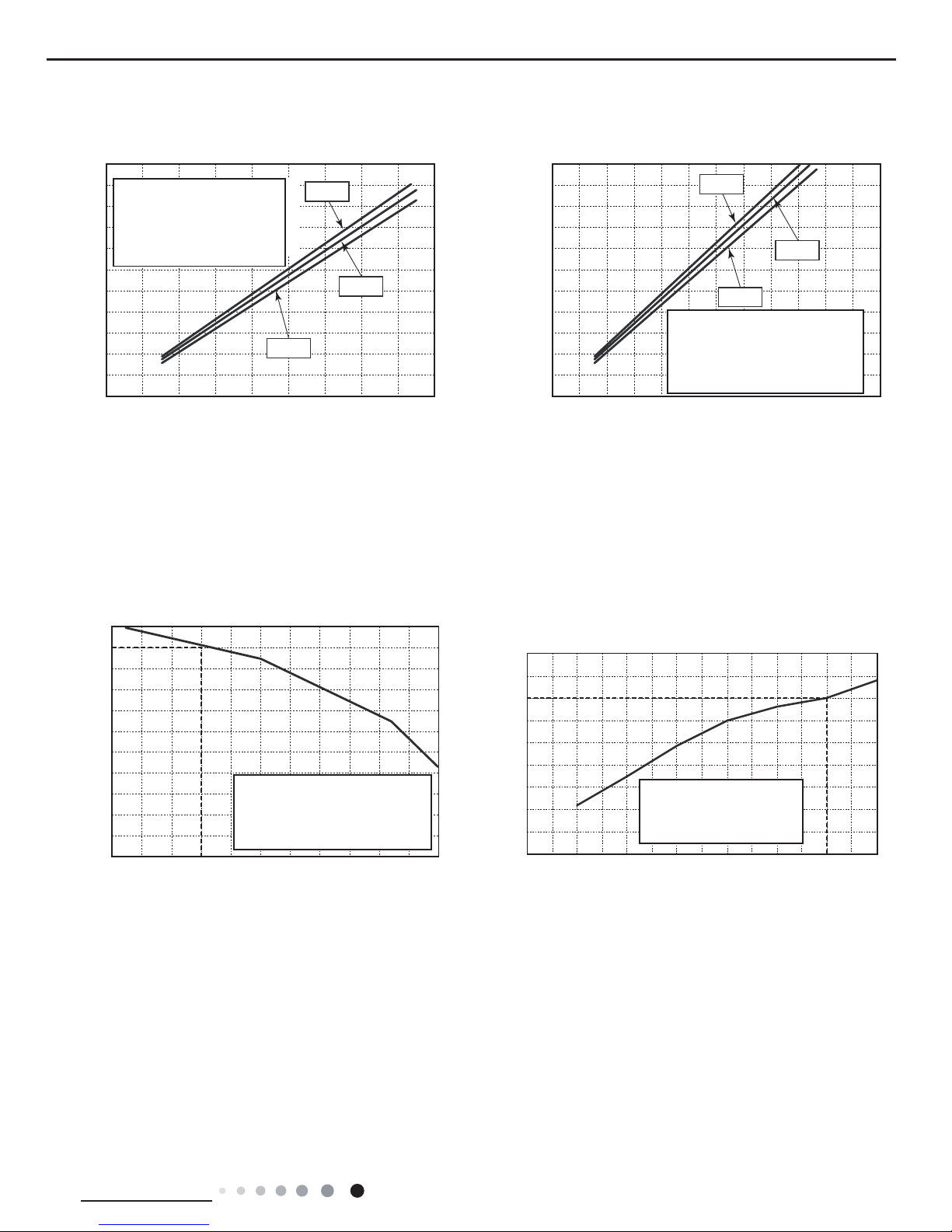
2.2 Operation Characteristic Curve
2.3 Capacity Variation Ratio According to Temperature
Cooling Heating
01020304050607090 0102030405060708090100 12
0
110
80
11
10
9
8
7
6
5
4
3
2
1
0
11
10
9
8
7
6
5
4
3
2
1
0
220V
230V
240V
220V
230V
240V
Current (A)
Current (A)
Conditions
Indoor:DB27°C/WB19°C
Outdoor:DB35°C/WB24°C
Indoor air flow:Super High
Pipe length:5m
Conditions
Indoor:DB20°C/WB15°C
Outdoor:DB7°C/WB6°C
Indoor air flow:Super High
Pipe length:5m
Compressor speed (rps) Compressor speed (rps)
Cooling Heating
32 33 34 35 36 37 38 39 43
40 41 42
100
105
95
90
85
80
75
70
65
60
55
50
Conditions
Indoor:DB27°C/WB19°C
Indoor air flow:Super High
Pipe length: 5m
Outdoor temp.(°C)
Capacity ratio (%)
30
40
50
60
70
80
90
100
110
120
10
750-5-10-15-20
Outdoor temp.(oC)
Capacity ratio(%)
Conditions
Indoor:DB20°C/WB15°C
Indoor air flow:Super High
Pipe length: 5m
Cooling Heating
6
Technical Information
Service Manual
2.4 Cooling and Heating Data Sheet in Rated Frequency
Instruction:
T1: Inlet and outlet pipe temperature of evaporator
T2: Inlet and outlet pipe temperature of condenser
P: Pressure at the side of big valve
Connection pipe length: 5 m.
Cooling:
Heating:
Rated cooling
condition(
o
C) (DB/WB)
Model
Pressure of gas pipe
connecting indoor
and outdoor unit
Inlet and outlet pipe
temperature of heat
exchanger
Fan speed
of indoor
unit
Fan speed
of outdoor
unit
Compressor
frequency
(Hz)
Indoor Outdoor P (MPa) T1 (
o
C) T2 (oC)
27/19 35/24 12K 0.8 ~ 1.1 11 to 14 38 to 41 Super High High 72
Rated heating
condition(
o
C) (DB/WB)
Model
Pressure of gas pipe
connecting indoor and
outdoor unit
Inlet and outlet pipe
temperature of heat
exchanger
Fan speed
of indoor
unit
Fan speed
of outdoor
unit
Compressor
frequency
(Hz)
Indoor Outdoor P (MPa) T1 (°C) T2 (°C)
20/15 7/6 12K 2.8 ~ 3.2 38 to 41 2 to 5 Super High High 77
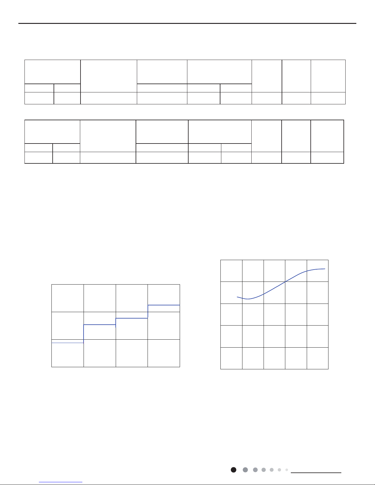
2.5 Noise Curve
Indoor side noise
Outdoor side noise
Indoor fan motor rotating speed
Compressor frequency/Hz
Low Middle High Supper High
Noise/dB(A)
Noise/dB(A)
70
60
50
30
40
20
50
40
30
02040608
0100
20
18K
7
Technical Information
Service Manual
W
D
H
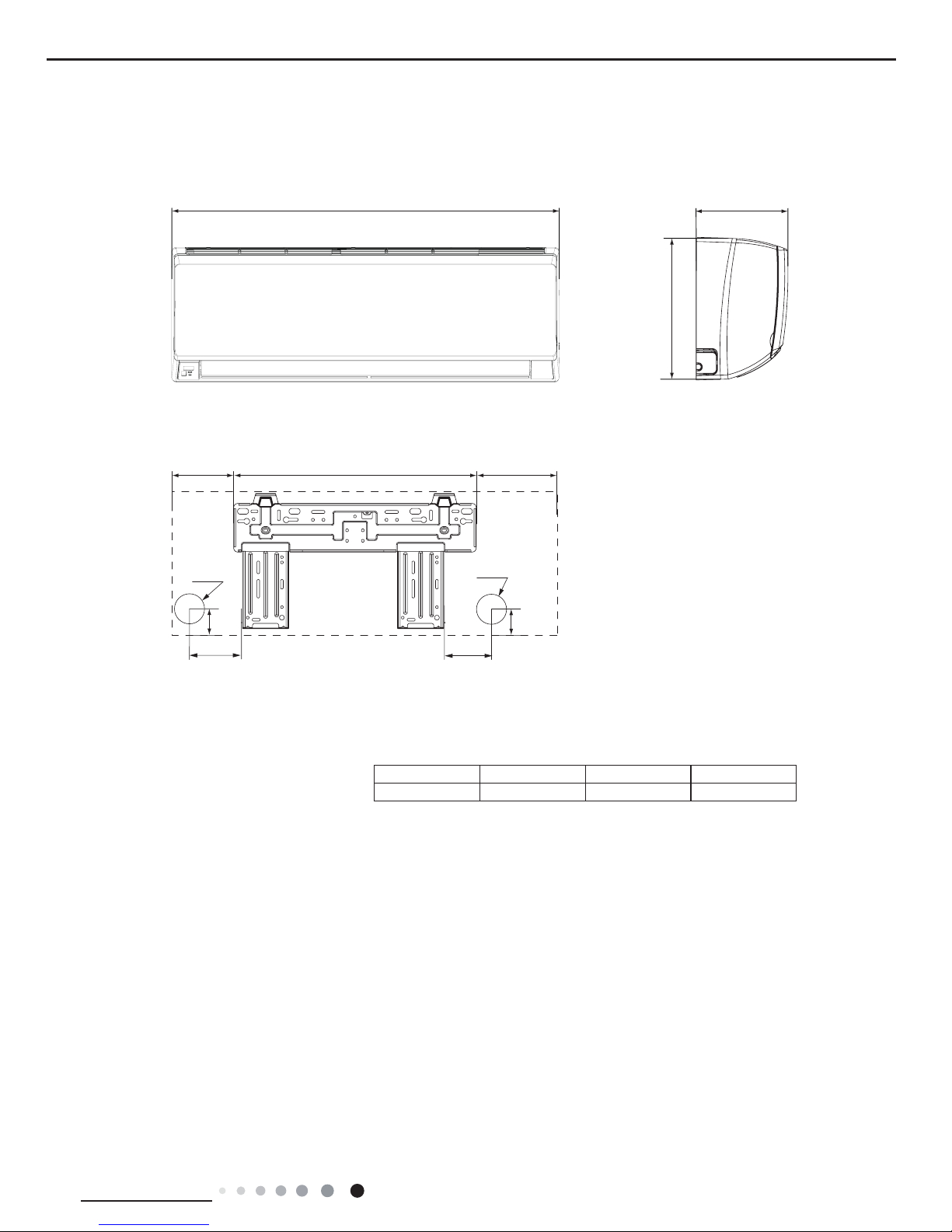
90
150
54
168.5 462 159.5
Φ55
Φ55
54
3. Outline Dimension Diagram
3.1 Indoor Unit
Unit:mm
Unit:mm
Models W H D
12K 790 275 200
8
Technical Information
Service Manual
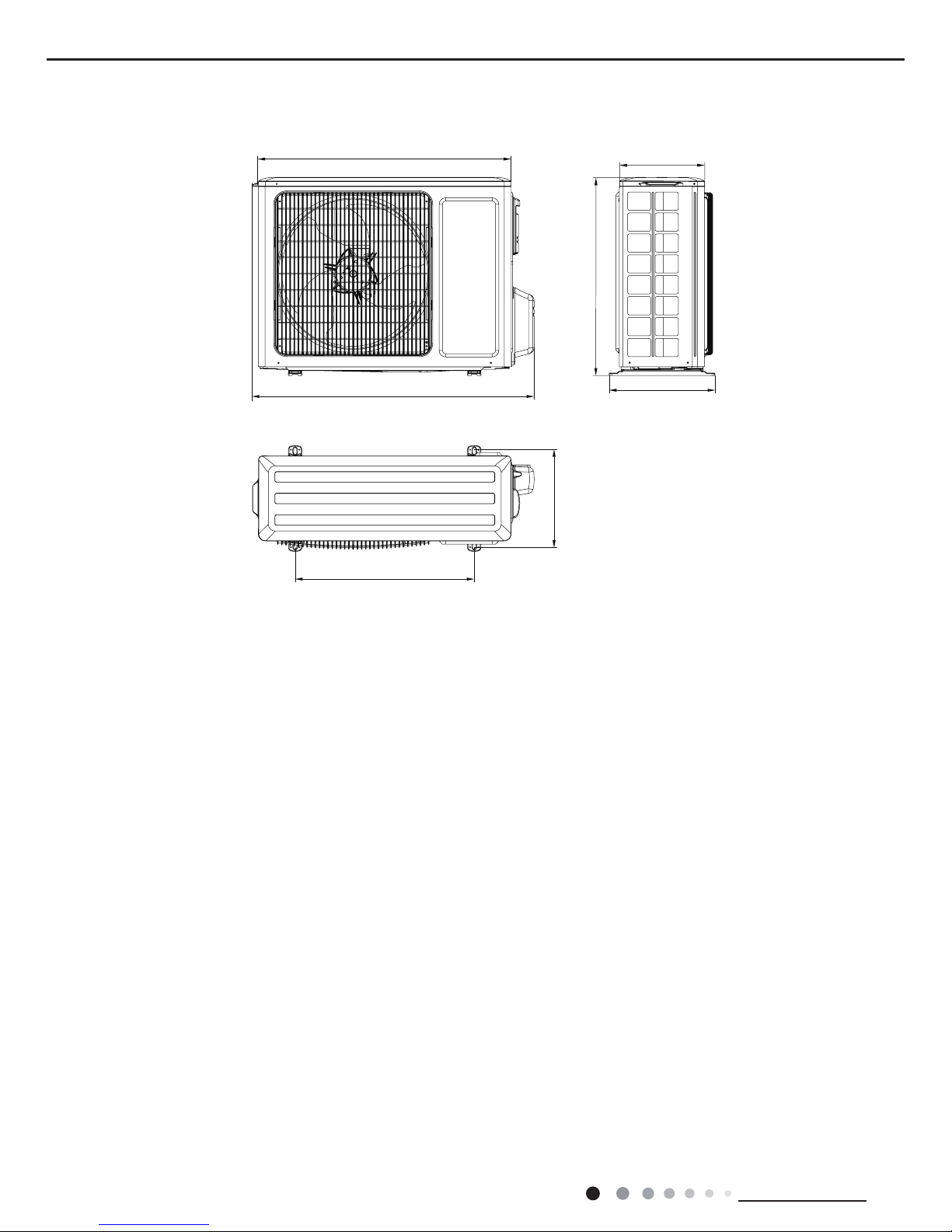
3.2 Outdoor Unit
Unit:mm
780
596
848
286
540
320
257
9
Technical Information
Service Manual
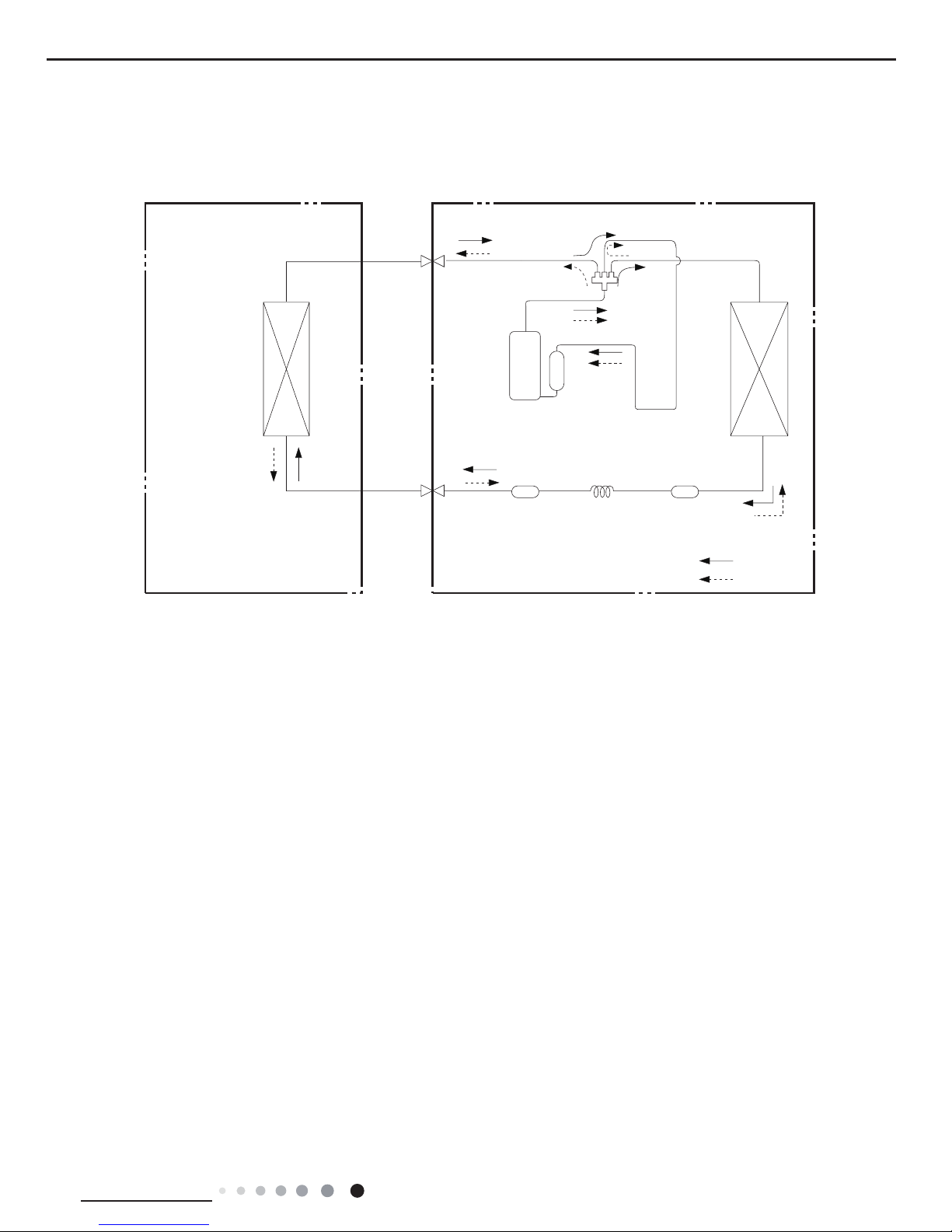
4. Refrigerant System Diagram
Indoor unit
Outdoor unit
COOLING
HEATING
4-Way valve
Discharge
Suction
Heat
exchanger
(evaporator)
Heat
exchanger
(condenser)
Valve
Valve
Liquid pipe
side
Gas pipe
side
Strainer CapillaryStrainer
Accumlator
Compressor
Connection pipe specication:
Liquid pipe:1/4" (6mm)
Gas pipe:3/8" (9.52mm)
Cooling and heating model
10
Technical Information
Service Manual
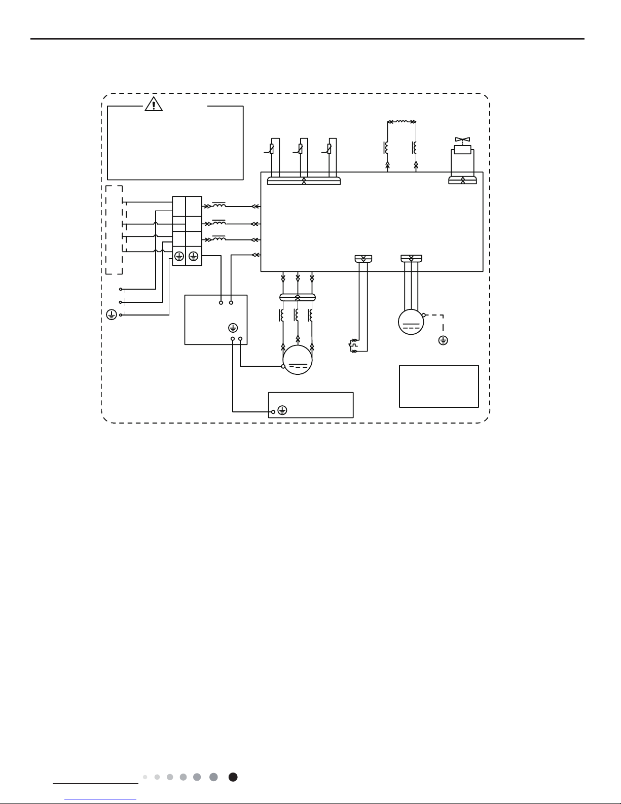
5. Electrical Part
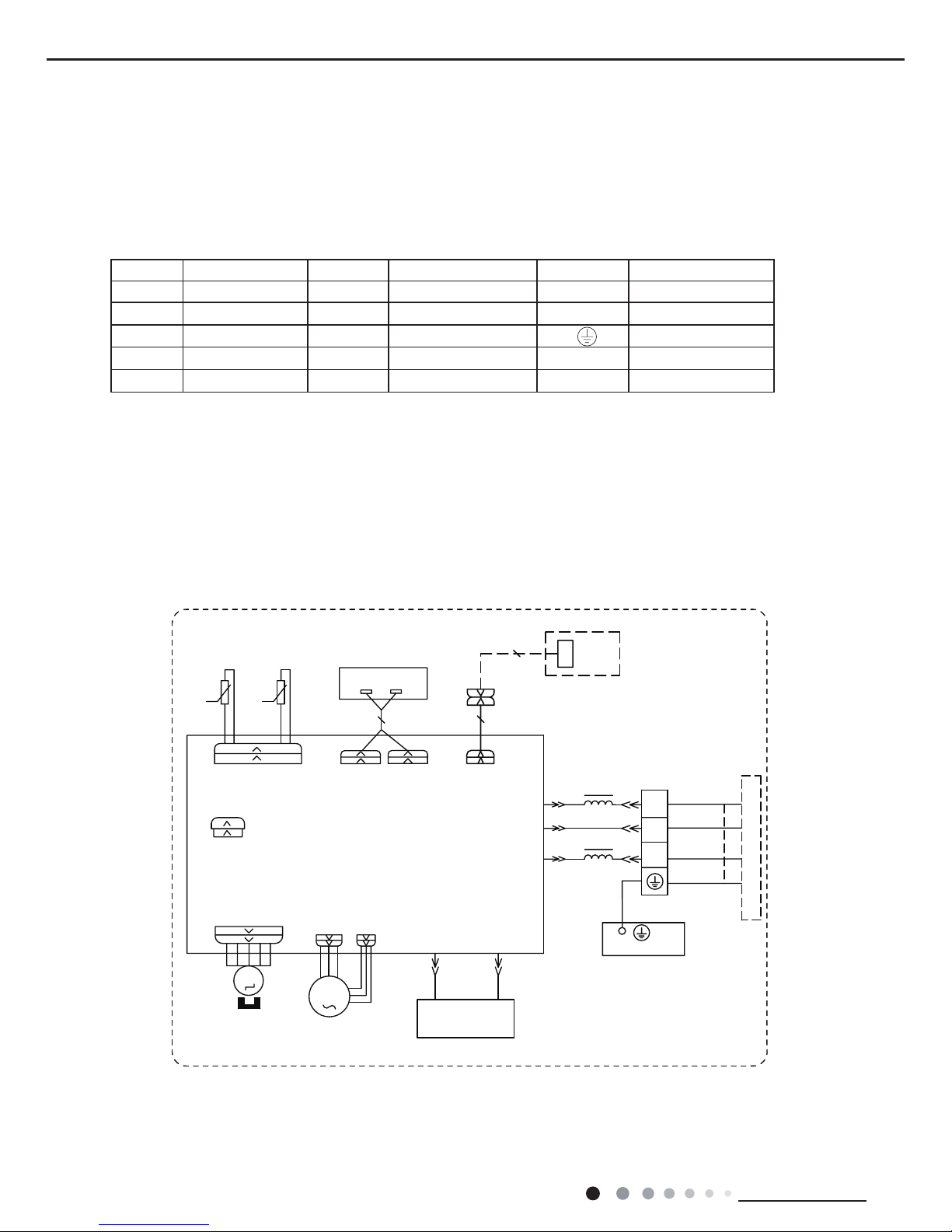
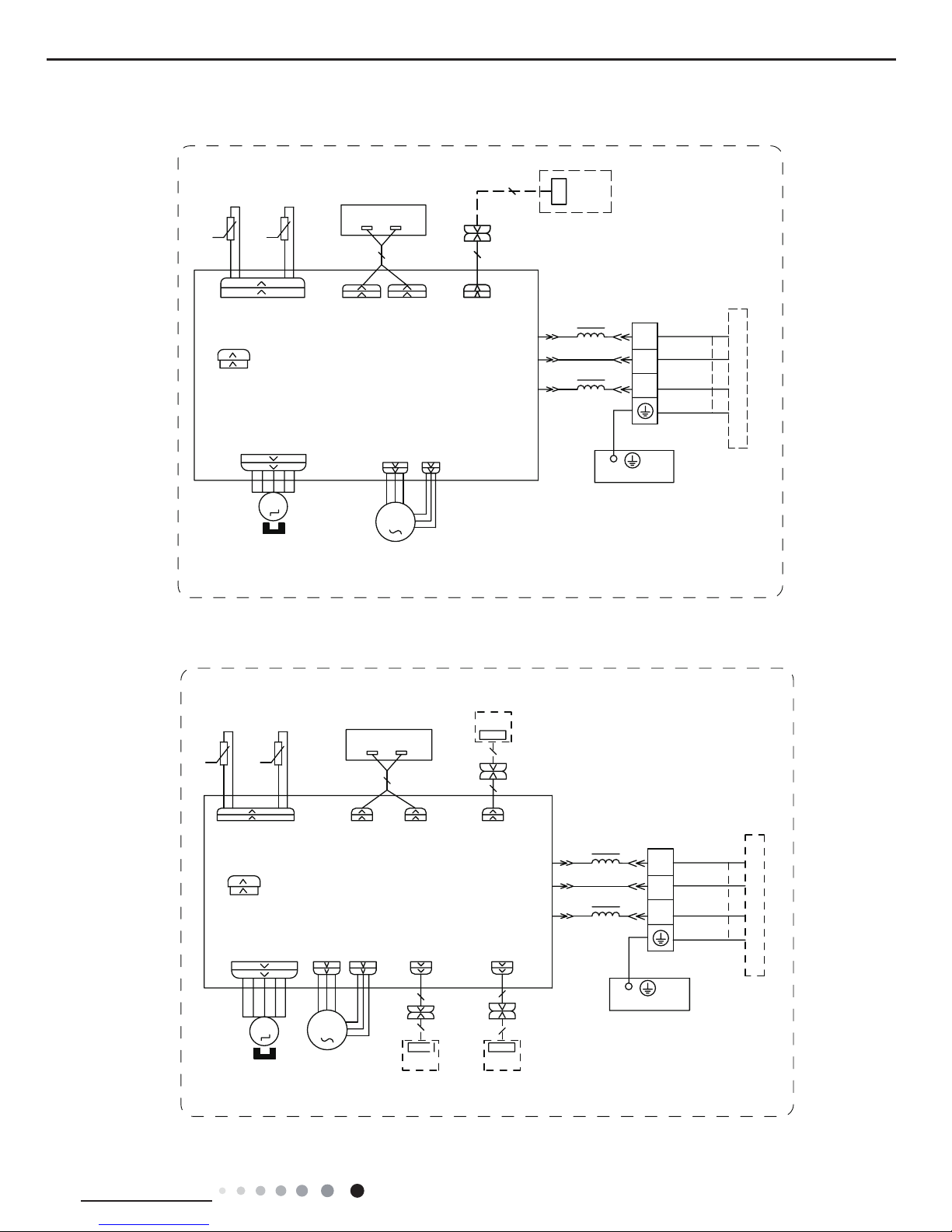
5.1 Wiring Diagram
● Indoor Unit
●Instruction
Symbol Symbol Color Symbol Symbol Color Symbol Name
WH White GN Green CAP Jumper cap
YE Yellow BN Brown COMP Compressor
RD Red BU Blue Grounding wire
YEGN Yellow/Green BK Black / /
VT Violet OG Orange / /
Note: Jumper cap is used to determine fan speed and the swing angle of horizontal lover for this model.
76(1625
7(03
6(1625
7(03
6(1625
57
5220
78%(
67(33,1*
',63/$<
35,17('&,5&8,7%2$5'
5(&(,9(5$1'
',63/$<%2$5'
&$%/(
&211(&7,1*
6:,1*8'
02725
%/2&.
7(50,1$/
$3
-803
&$3
%8
%.
<(*1
(9$325$725
3(
;7
1
0
287'22581,7
$3
3*
*(1(5$725
&2/'3/$60$
)$102725
0
5' %8
+($/7+1
+($/7+/
3*)
',63
',63
%1
<(*1
57
1
&20287
/
%8
%.
%1
/
/
:,),02'8/(
$3
&200$18$/
:,),
GWH12QB-K6DNB8I/I(CB438N06800) GWH12QB-K6DNB2I/I GWH12QB-K6DNB4I/I GWH12QB-K6DNA1I/I
GWH12QB-K6DNA5I/I GWH12QB-K6DND6I/I GWH12QB-K6DNA3I/I GWH12QB-K6DNC6I/I
GWH12QB-K6DNC8I/I
6363222005
11
Technical Information
Service Manual
6363222004
76(1625
7(03
6(1625
7(03
6(1625
57
5220
78%(
67(33,1*
',63/$<
35,17('&,5&8,7%2$5'
5(&(,9(5$1'
',63/$<%2$5'
&$%/(
&211(&7,1*
6:,1*8'
02725
%/2&.
7(50,1$/
$3
-803
&$3
%8
%.
<(*1
(9$325$725
3(
;7
1
0
287'22581,7
$3
3*
)$102725
0
3*)
',63
',63
%1
<(*1
57
1
&20287
/
%8
%.
%1
/
/
:,),02'8/(
$3
&200$18$/
:,),
GWH12QB-K6DND6I/I GWH12QB-K6DNB8I/I(CB438N06801)
GWH12QB-K6DNB4I/I
GWH12QB-K6DNC4I/I(CB444N07501)
76(1625
7(03
6(1625
7(03
6(1625
57
522078%(
67(33,1*
',63/$<
35,17('&,5&8,7%2$5'
5(&(,9(5$1'
',63/$<%2$5'
&$%/(
&211(&7,1*
6:,1*8'
02725
%/2&.
7(50,1$/
$3
-803
&$3
%8
%.
<(*1
(9$325$725
3(
;7
1
0
287'22581,7
$3
3*
)$102725
0
3*)
',63 ',63
%1
<(*1
57
1
&20287
%8
%.
%1
/
/
:,),
02'8/(
:,),
$3
:,5('
&21752//(5
&200$18$/
$3
'5<&
'225&
237,21$/
'5<&217$&7
$&//
$3
0$*1(7,&
5,1*
60000700068806
12
Technical Information
Service Manual
GWH12QB-K6DNB8I/I(CB438N06802)
60000700068803
:,5('
&21752//(5
&200$18$/
76(1625
7(03
6(1625
7(03
6(1625
57
522078%(
67(33,1*
',63/$<
35,17('&,5&8,7%2$5'
5(&(,9(5$1'
',63/$<%2$5'
&$%/(
&211(&7,1*
6:,1*8'
02725
%/2&.
7(50,1$/
$3
-803
&$3
%8
%.
<(*1
(9$325$725
3(
;7
1
0
287'22581,7
$3
3*
*(1(5$725
&2/'3/$60$
)$102725
0
5' %8
+($/7+1
+($/7+/
3*)
',63 ',63
%1
<(*1
57
1
&20287
$&/
%8
%.
%1
/
/
:,),
02'8/(
:,),
$3
$3
$3
'5<&
'225&
237,21$/
'5<&217$&7
0$*1(7,&
5,1*
13
Technical Information
Service Manual
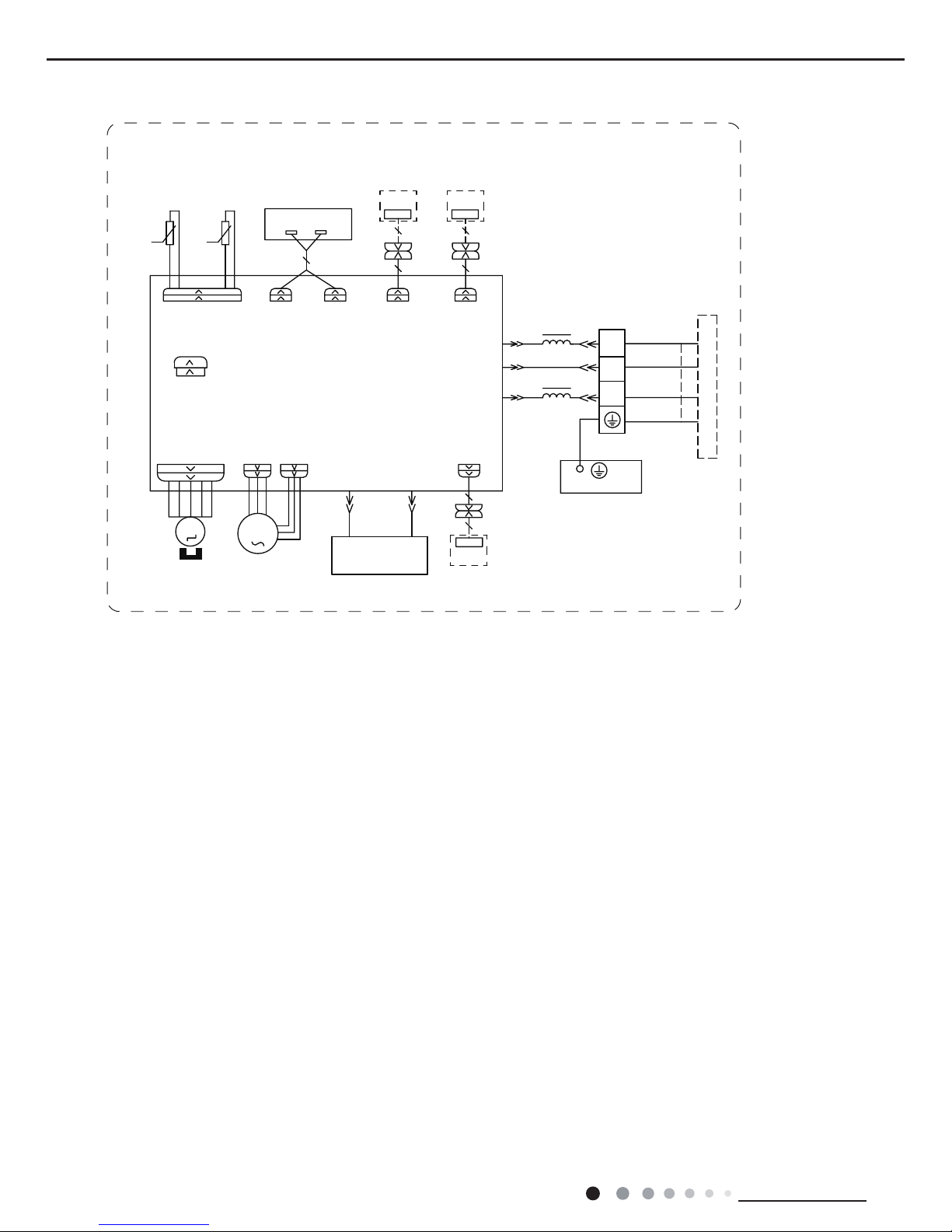
● Outdoor Unit
These wiring diagrams are subject to change without notice; please refer to the one supplied with the unit.
RIHOHFWULFVKRFN
3OHDVHGRQWWRXFKDQ\
WHUPLQDOZKHQWKHPDFKLQHLV
UXQQLQJVWRSSLQJRUKDVEHHQ
SRZHUHGRIIIRUOHVVWKDQ
PLQXWHVWRSUHYHQWWKHULVN
:$51,1*
<(*1
%8
%.
%1
1
/
1
/
/
%8
%1
0$*1(7,&5,1*
7(50,1$/
;7
%/2&.
1
&208
3(
&1
7(03
6(1625
7(03
6(1625
7(03
57
57
57
6(1625
N
N
N
28778%(
2875220
(;+$867
<9
:$<
:$<
9$/9(
97
97
/;
/;
/
/
5($&725
/
%8
%1
0$*1(7,&
5,1*
$30DLQ%RDUG
2)$1
)$1
0
3(
3(
<(*1
02725
3527(&725
29(5/2$'
5'
29&&203
6$7
5'
/
:
9
8
&203
&203
:
9
8
;
%8
<(
5'
0$*1(7,&
5,1*
32:(5
/
1
<(*1
%8
%1%.
<(*1
<(*1
3(
<(*1
(/(&75,&$/
%2;
3(
0,',62/$7,21
6+((7
3(
<(*1
%8
<(
5'
/
%.
$&/$&/
60000700076302
127(0RWRU
DSSOLHVWRWKH
LURQVKHOOPRWRU
JURXQGRQO\
,1'22581,7
14
Technical Information
Service Manual
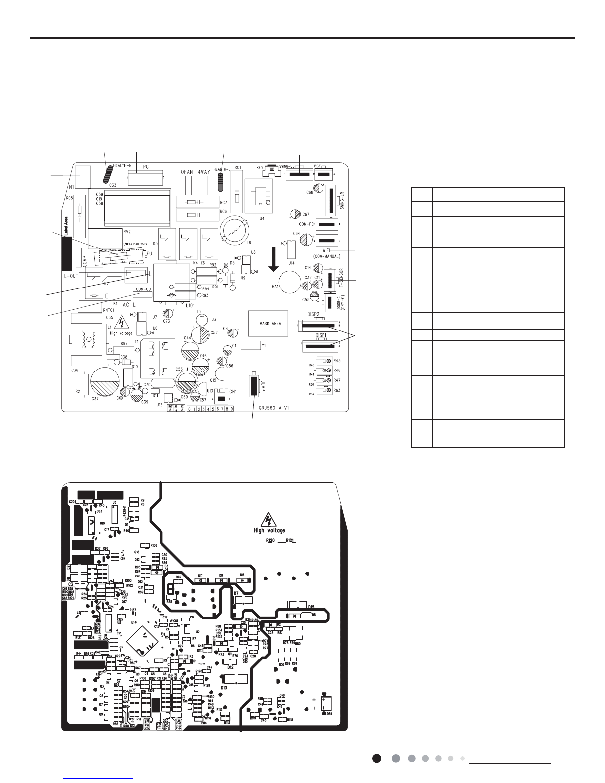
5.2 PCB Printed Diagram
Indoor Unit
All models except GWH12QB-K6DNC4I/I GWH12QB-K6DNB8I/I
● Top view
● Bottom view
NO. Name
1
2
3
Communication wire
Live wire
4
Fuse
5
Neutral wire
6
PG fan interface
Auto button
up&down swing interface
Interface of PG feedback
7
8
9
10
11
Needle stand for WiFi
12
Interface of temperature sensor
Interface of display board
Jumper
13
2
1
3
4
10
9
11
12
68
7
513 14
Neutral wire for health function
(Applicable for some models)
14
Live wire for health
(Applicable for some models)
15
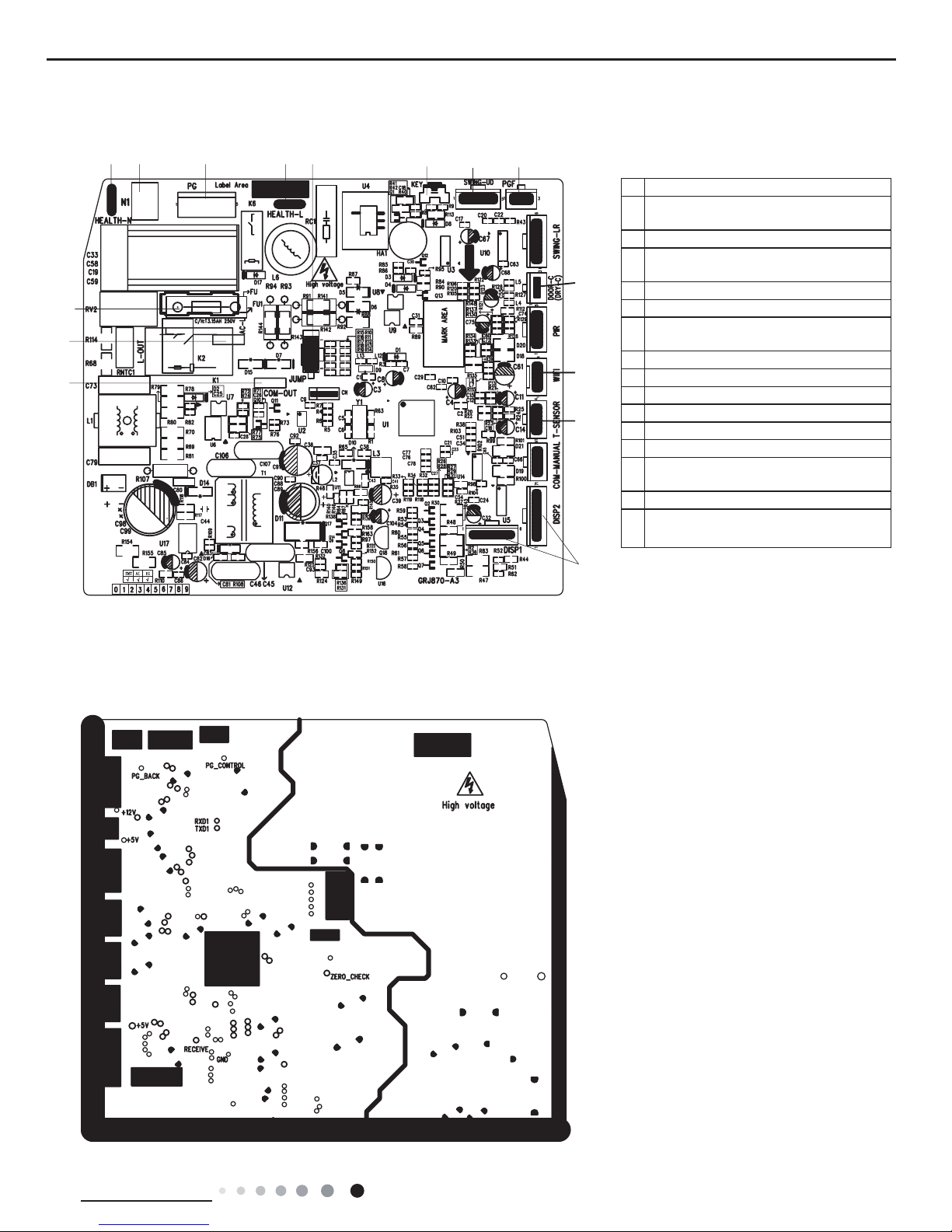
Technical Information
Service Manual
Indoor Unit
No Name
1
Interface of communication wire for
indoor unit and outdoor unit
2 Interface of live wire
3
Interface of health function neutral wire
(Only for the mode with this function)
4 Interface of neutral wire
5 Interface of fan
6
Interface of health function live wire
(Only for the mode with this function)
7 Jumper cap
8 Auto button
9 Up&down swing interface
10 Feedback interface of indoor unit
11 Fuse
12 Interface of wi
13
Needle stand for tube temperature
sensor
14 Display interface
15
Gateway interface(Only for the mode
with this function)
● Top view
● Bottom view
1
2
11
3
4 5
6
7
8
9
10
12
13
14
15
GWH12QB-K6DNC4I/I GWH12QB-K6DNB8I/I
16
Technical Information
Service Manual
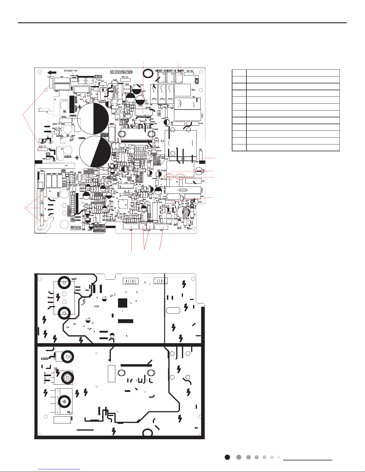
Outdoor Unit
● Top view
● Bottom view
No. Name
1 Interface of compressor wire
2 Interface of reactor
3 Fan terminal
4 Interface of 4-way valve
5 Terminal of electronic expansion valve
6 Grounding wire
7 Live wire
8 Neutral wire
9 Communication wire
10 Overload interface of compressor
11 Interface of temperature sensor
2
3
4
6
7
8
5
9
10
11
1
17
Technical Information
Service Manual
6. Function and Control
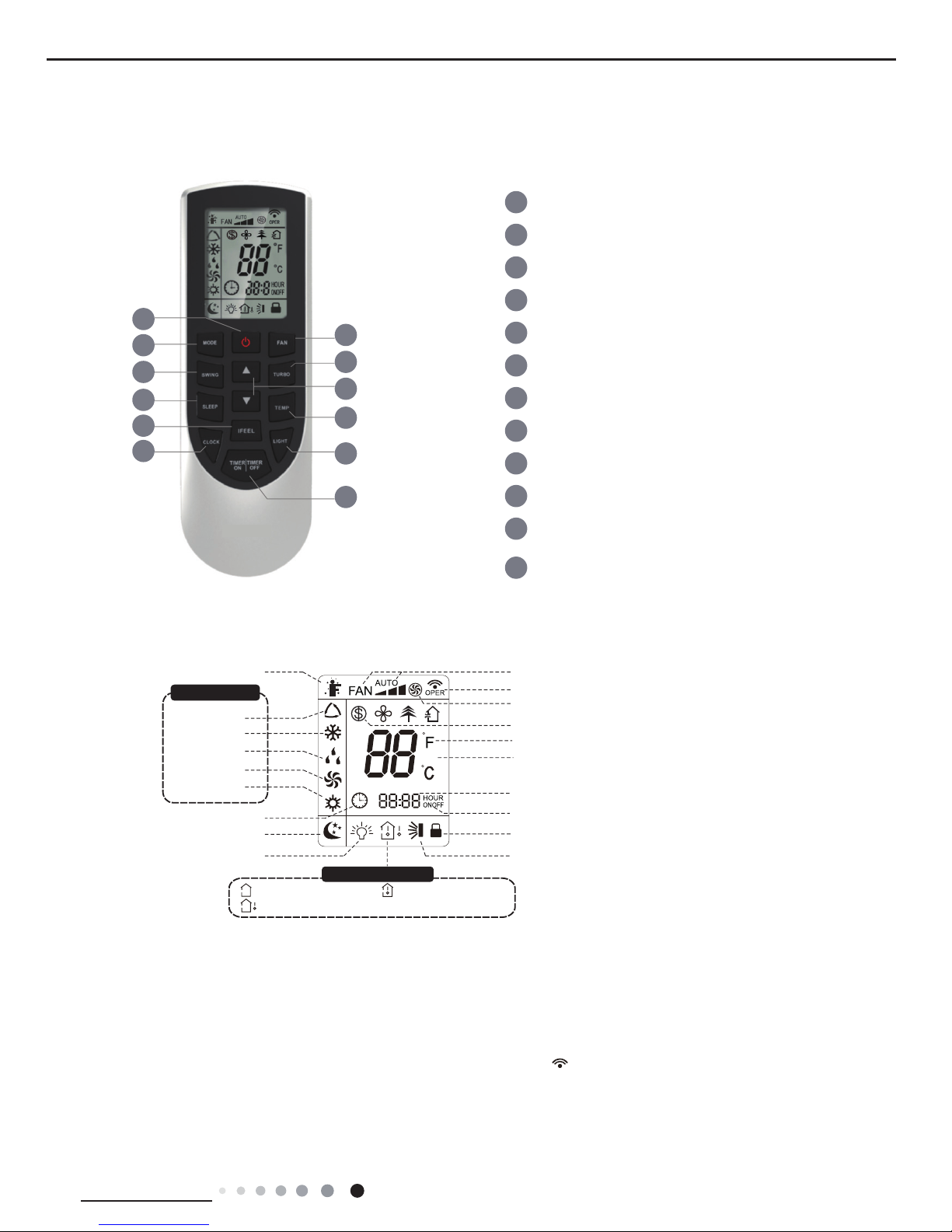
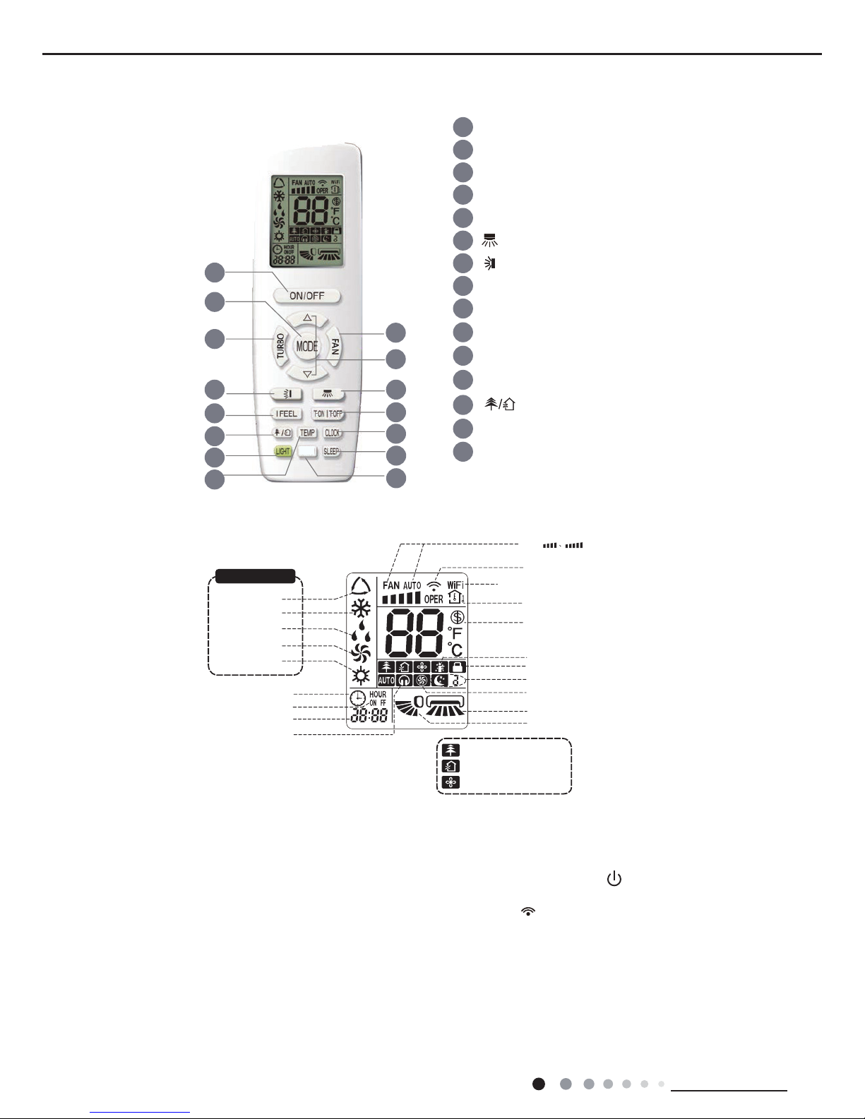
6.1 Remote Controller Introduction of YAN1F6(WiFi)
Buttons on Remote Controller
Introduction for icons on display screen
Introduction for buttons on remote controller
WiFi
1
5
3
6
8
10
12
11
9
7
4
2
1
2
3
4
5
6
7
8
9
10
11
12
ON/OFF button
MODE button
FAN button
SWING button
TURBO button
TEMP button
WiFi button
LIGHT button
CLOCK button
TIMER ON / TIMER OFF
button
SLEEP button
▲/ button
▲
WiFi
Send signal
Turbo mode
8℃ heating function
Set temperature
Set time
TIMER ON / TIMER OFF
Child lock
Up & down swing
Set fan speed
Light
Temp. display type
:Set temp.
:Outdoor ambient temp.
:Indoor ambient temp.
Sleep mode
Clock
Heat mode
Fan mode
Dry mode
Cool mode
Auto mode
Operation mode
I feel
Note:
● This is a general use remote controller, it could be used for the air conditionerswith multifunction; For some function, which the
model doesnt have, if pressthe corresponding button on the remote controller that the unit will keep theoriginal running status.
● After putting through the power, the air conditioner will give out a sound. Operation indicator is ON (red indicator, the colour is
different for different models).After that,you can operate the air conditioner by using remote controller.
●
Under on status, pressing the button on the remote controller, the signal icon " "
on the display of remote controller will blink once
and the air conditioner will give out a “de” sound, which means the signal has been sent to the air conditioner.
● Under off status, set temperature and clock icon will be displayed on the display of remote controller (If timer on, timer off and light
functions are set, the corre- sponding icons will be displayed on the display of remote controller at the same
time); Under on status,
the display will show the corresponding set function icons.
WIFI(This is a general remote controller.Some models have this
function while some do not. Please refer to the actual models.)
18
Technical Information
Service Manual
1. ON/OFF button
2. MODE button
3. FAN button
Press this button to turn on the unit. Press this button again to turn off the unit.
● When selecting auto mode, air conditioner will operate automatically according to ex-factory setting. Set temperature cant be adjusted and
will not be displayed as well. Press "FAN" button can adjust fan speed. Press "SWING" button can adjust fan blowing angle.
● After selecting cool mode, air conditioner will operate under cool mode. Cool indicator on indoor unit is ON(This indicator is not available
for some models). Press "▲" or "
▲
" button to adjust set temperature. Press "FAN" button to adjust fan speed. Press "SWING" button to
adjust fan blowing angle.
● When selecting dry mode, the air conditioner operates at low speed under dry mode. Dry indicator on indoor unit is ON(This indicator is
not available for some models). Under dry mode, fan speed cant be adjusted. Press "SWING" button to adjust fan blowing angle.
● When selecting fan mode, the air conditioner will only blow fan, no cooling and no heating. All indicators are OFF. Press "FAN" button to
adjust fan speed. Press "SWING" button to adjust fan blowing angle.
● When selecting heating mode, the air conditioner operates under heat mode. Heat indicator on indoor unit is ON(This indicator is not
available for some models). Press "▲" or "
▲
"button to adjust set temperature. Press "FAN" button to adjust fan speed. Press "SWING"
button to adjust fan blowing angle. (Cooling only unit wont receive heating mode signal. If setting heat mode with remote controller, press
ON/OFF button cant start up the unit).
Note:
● For preventing cold air, after starting up heating mode, indoor unit will delay 1~5 minutes to blow air (actual delay time is depend on indoor
ambient temperature).
● Set temperature range from remote controller: 16~30℃; Fan speed: auto, low speed, medium speed, high speed.
5. TURBO button
Under COOL or HEAT mode, press this button to turn to quick COOL or quick HEAT mode. "
" icon is displayed on remote controller.
Press this button again to exit turbo function and "
" icon will disappear.
6. ▲/
▲
button
● Press "▲" or "
▲
" button once increase or decrease set temperature 1℃. Holding "▲" or "▲" button, 2s later, set temperature on remote
controller will change quickly. On releasing button after setting is nished, temperature indicator on indoor unit will change accordingly.
(Temperature cant be adjusted under auto mode)
● When setting TIMER ON, TIMER OFF or CLOCK, press "▲" or "▲" button to adjust time. (Refer to CLOCK, TIMER ON, TIMER OFF
buttons) When setting TIMER ON, TIMER OFF or CLOCK, press "▲" or "▲" button to adjust time. (Refer to CLOCK, TIMER ON, TIMER
OFF buttons)
Caution:
● Under AUTO speed, air conditioner will select proper fan speed automatically according to ex-factory setting.
● Fan speed under dry mode is low speed.
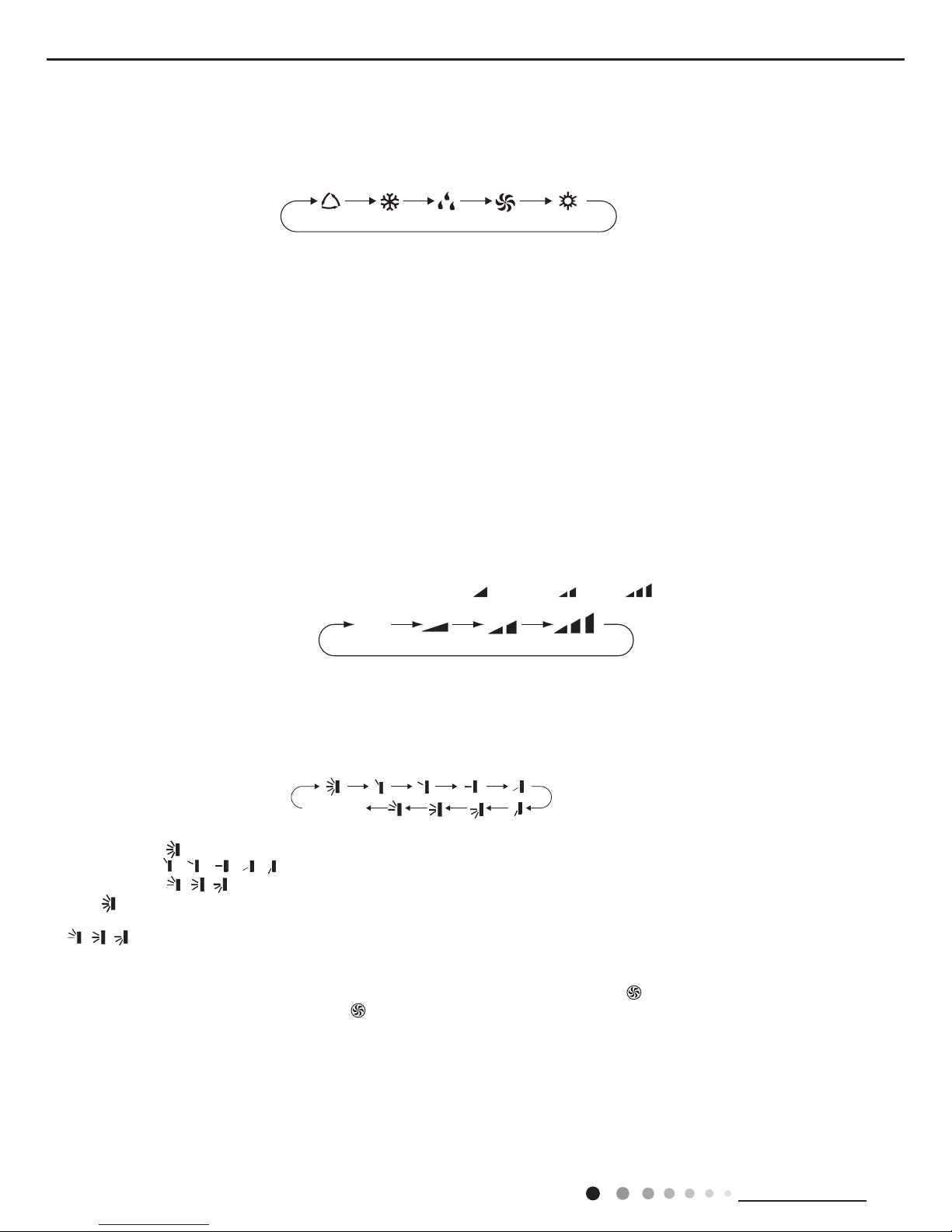
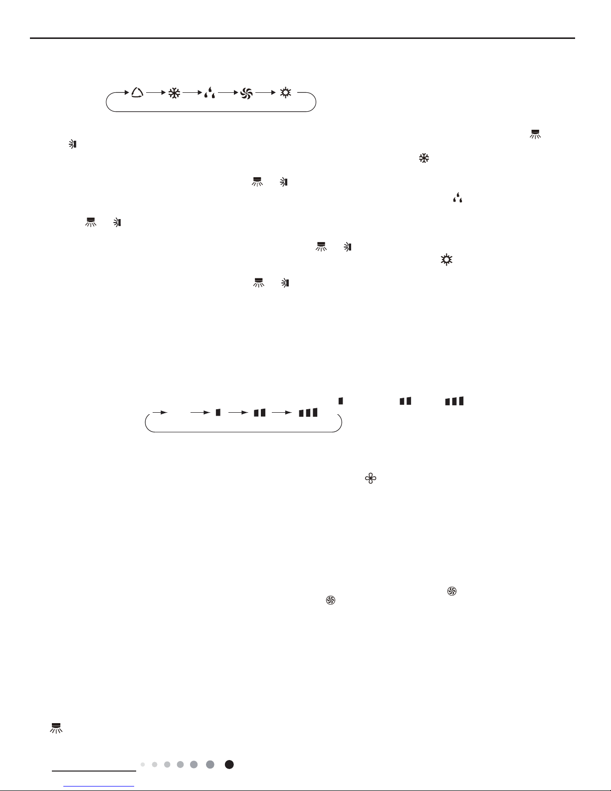
Pressing this button can set fan speed circularly as: auto (AUTO), low(
) ,medium( ), high( ).
Press this button to select your required operation mode.
AUTO COOL FANDRY
HEAT
Auto
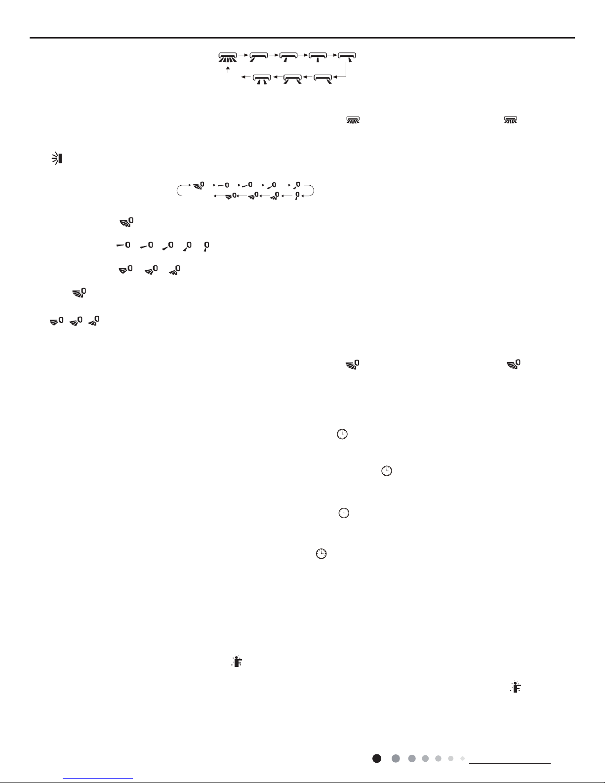
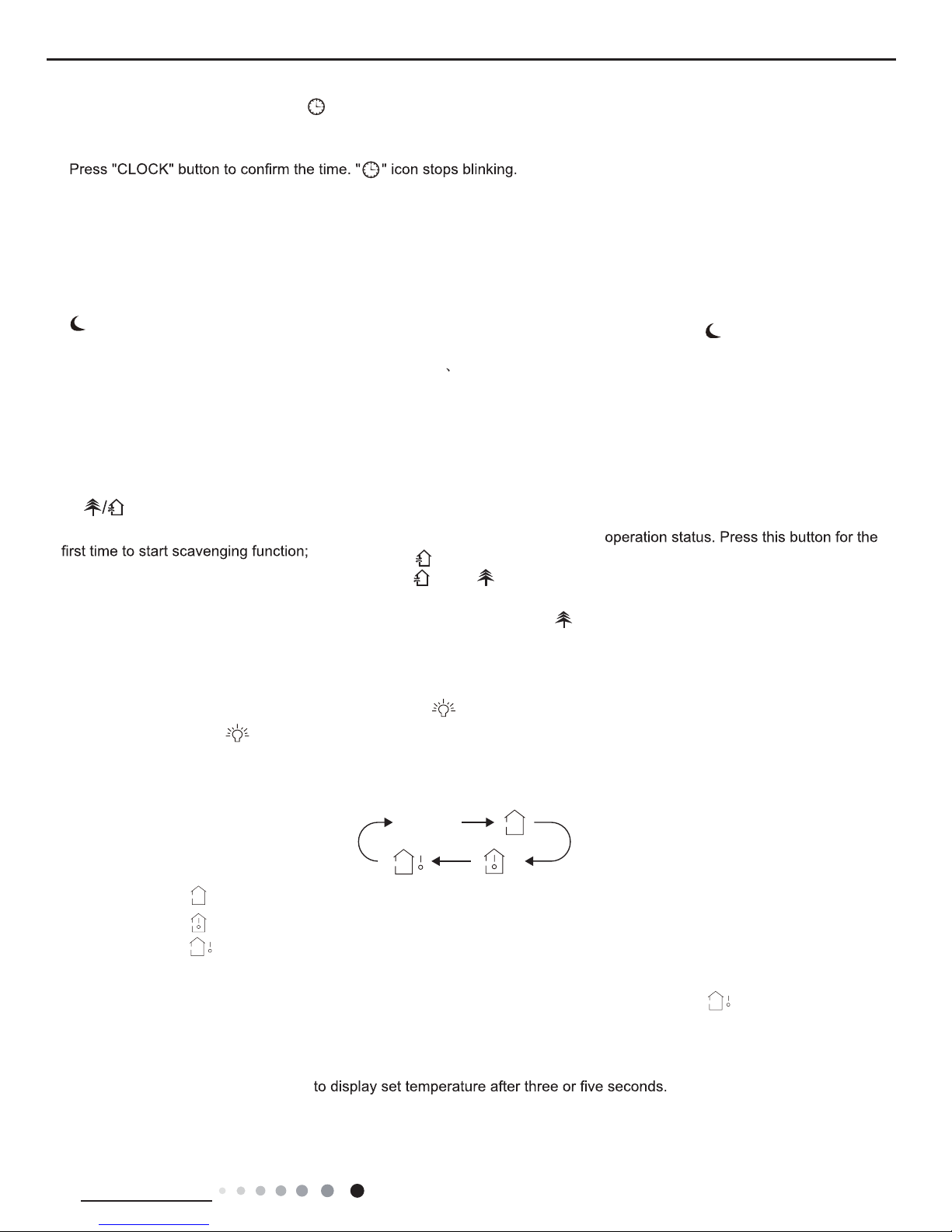
4. SWING button
Press this button can select up&down swing angle. Fan blow angle can be selected circularly as below:
● When selecting "
", air conditioner is blowing fan automatically. Horizontal louver will automatically swing up & down at maximum angle.
● When selecting " 、 、 、 、 ", air conditioner is blowing fan at xed position. Horizontal louver will stop at the xed position.
● When selecting " 、 、 " , air conditioner is blowing fan at xed angle. Horizontal louver will send air at the xed angle.
● Hold " "button above 2s to set your required swing angle. When reaching your required angle, release the button.
Note:
● " 、 、 " may not be available. When air conditioner receives this signal, the air conditioner will blow fan automatically.
no display
(horizontal louvers stops at current position)
19
Technical Information
Service Manual
7. SLEEP button
9. WiFi button
10. LIGHT button
11. CLOCK button
12. TIMER ON / TIMER OFF button
Under COOL, HEAT or DRY mode, press this button to start up sleep function. "
" icon is displayed on remote controller. Press this button
again to cancel sleep function and "
" icon will disappear.
Press " WiFi " button to turn on or turn off WiFi function. When WiFi function is turned on, the " WiFi " icon will be displayed on remote
controller; Under status of remote controller off, press "MODE" and " WiFi " buttons simultaneously for 1s,WiFi modulewill restore to factory
default setting.
Press this button to turn off display light on indoor unit. "
" icon on remote controller disappears. Press this button again to turn on
display light. "
" icon is displayed.
Press this button to set clock time. "
" icon on remote controller will blink. Press "▲" or "▲" button within 5s to set clock time. Each
pressing of "▲" or "
▲
" button, clock time will increase or decrease 1 minute. If hold "▲" or "▲" button, 2s later, time will change quickly.
Release this button when reaching your required time. Press "CLOCK" button to conrm the time. "
" icon stops blinking.
Note:
● Clock time adopts 24-hour mode.
● The interval between two operation cant exceeds 5s. Otherwise, remote controller will quit setting status. Operation for TIMER ON/TIMER
OFF is the same.
● TIMER ON button
"TIMER ON" button can set the time for timer on. After pressing this button, "
" icon disappears and the word "ON" on remote controller
blinks. Press "▲" or "
▲
"button to adjust TIMER ON setting. After each pressing "▲" or "▲" button, TIMER ON setting will increase or
decrease 1min. Hold "▲" or "
▲
" button, 2s later, the time will change quickly until reaching your required time. Press "TIMER ON" to
conrm it. The word "ON" will stop blinking. "
" icon resumes displaying. Cancel TIMER ON: Under the condition that TIMER ON is
started up, press "TIMER ON" button to cancel it.
● TIMER OFF button
"TIMER OFF" button can set the time for timer off. After pressing this button,"
" icon disappears and the word "OFF" on remote
controller blinks. Press "▲" or "
▲
" button to adjust TIMER OFF setting. After each pressing "▲" or "▲" button,
TIMER OFF setting will increase or decrease 1min. Hold "▲" or "
▲
" button, 2s later, the time will change quickly until reaching your
required time. Press "TIMER OFF" word "OFF" will stop blinking. "
" icon resumes displaying. Cancel TIMER OFF. Under the condition
that TIMER OFF is started up, press "TIMER OFF" button to cancel it.
Note:
● Under on and off status, you can set TIMER OFF or TIMER ON simultaneously.
● Before setting TIMER ON or TIMER OFF, please adjust the clock time.
● After starting up TIMER ON or TIMER OFF, set the constant circulating valid. After that, air conditioner will be turned on or turned off
according to setting time. ON/OFF button has no effect on setting. If you dont need this function, please use remote controller to cancel it.
8. TEMP button
By pressing this button, you can see indoor set temperature, indoor ambient temperature or outdoor ambient temperature on indoor units
display. The setting on remote controlleris selected circularly as below:
● When selecting "
" or no display with remote controller, temperature indicator on indoor unit displays set temperature.
● When selecting "
" with remote controller, temperature indicator on indoor unit displays indoor ambient temperature.
● When selecting "
" with remote controller, temperature indicator on indoor unit displays outdoor ambient temperature.
Note:
●
Outdoor temperature display is not available for some models. At that time, indoor
unit receives " "signal, while it displays indoor set
temperature.
● Its defaulted to display set temperature when turning on the unit.There is no display in the remote controller.
● Only for the models whose indoor unit has dual-8 display.
● When selecting displaying of indoor or outdoor ambient temperature, indoor temperature indicator displays corresponding temperature and
automatically turn to display set temperature after three or ve seconds.
no display
20
Technical Information
Service Manual
Function introduction for combination buttons
Operation guide
1. Energy-saving function
1. After putting through the power, press "ON/OFF" button on remote controller to turn on the air conditioner.
2. Press "MODE" button to select your required mode: AUTO, COOL, DRY, FAN, HEAT.
3. Press "▲" or "
▲
" button to set your required temperature. (Temperature cant be adjusted under auto mode).
4. Press "FAN" button to set your required fan speed: auto, low, medium and high speed.
5. Press "SWING" button to select fan blowing angle.
2. 8 ℃ heating function
3. Child lock function
4. Temperature display switchover function
Under cooling mode, press "TEMP" and " CLOCK" buttons simultaneously to start up or turn off energy-saving function. When energy-saving
function is started up, "SE" will be shown on remote controller, and air conditioner will adjust the set temperature automatically according to
ex-factory setting to reach to the best energy-saving effect. Press "TEMP" and "CLOCK"buttons simultaneously again to exit energy-saving
function.
Note:
● Under energy-saving function, fan speed is defaulted at auto speed and it cant be adjusted.
●
Under energy-saving function, set temperature cant be adjusted. Press "TURBO"
button and the remote controller wont send signal.
● Sleep function and energy-saving function cant operate at the same time. If energy-saving function has been set under cooling mode,
press sleep button will cancel energy-saving function. If sleep function has been set under cooling mode, start up the energy-saving
function will cancel sleep function.
Under heating mode, press "TEMP" and "CLOCK" buttons simultaneously to start
up or turn off 8℃ heating function. When this function is
started up, "
" and "8℃" will be shown on remote controller, and the air conditioner keep the heating status
at 8℃. Press "TEMP" and
"CLOCK" buttons simultaneously again to exit 8℃heating function.
Note:
● Under 8℃ heating function, fan speed is defaulted at auto speed and it cant be adjusted.
● Under 8℃ heating function, set temperature cant be adjusted. Press
"
TURBO" button and the remote controller wont send signal.
● Sleep function and 8℃ heating function cant operate at the same time. If 8℃heating function has been set under heating mode, press
sleep button will cancel 8℃ heating function. If sleep function has been set under heating mode, start up the 8℃ heating function will
cancel sleep function.
● Under ℉ temperature display, the remote controller will display 46℉ heating.
Press "▲" and "
▲
" simultaneously to turn on or turn off child lock function. When child lock function is on, " " icon is displayed on remote
controller. If you operate the remote controller, the "
" icon will blink three times without sending signal to the unit.
Under OFF status, press "
▲
" and "MODE" buttons simultaneously to switch temperature display between ℃ and ℉.
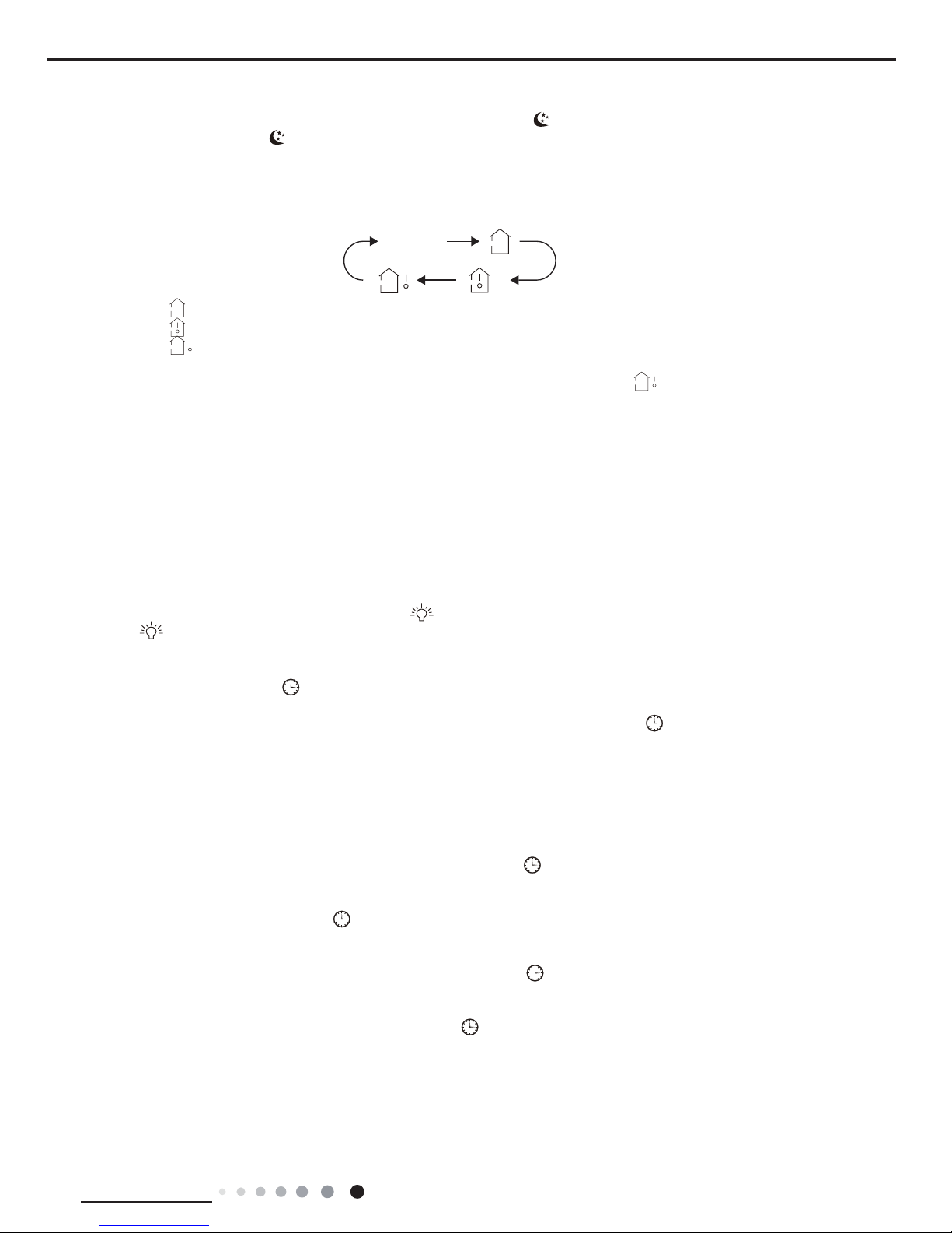
Health function
Health function will be set during operation of indoor fan.
Turn off the unit will also turn off health function.
This function is only available for some models.
I FEEL button
Press this button to start I FEEL function and "
" will be displayed on the remote controller. After this function is set, the remote controller
will send the detected ambient temperature to the controller and the unit will automatically adjust the indoor temperature according to the
detected temperature. Press this button again to close I FEEL function and "
" will disappear.
● Please put the remote controller near user when this function is set. Do not put the remote controller near the object of high temperature
or low temperature in order to avoid detecting inaccurate ambient temperature.
21
Technical Information
Service Manual
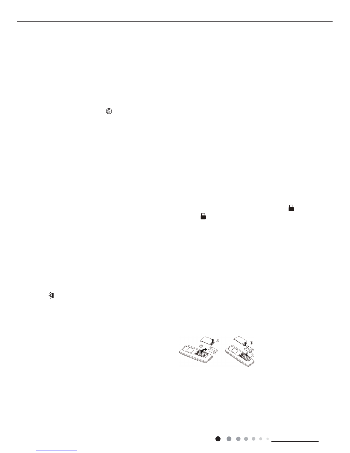
Replacement of batteries in remote controller
● During operation, point the remote control signal sender at the receiving window on indoor unit.
● The distance between signal sender and receiving window should be no more than 8m, and there should be no obstacles between them.
● Signal may be interfered easily in the room where there is uorescent lamp or wireless telephone; remote controller should be close to
indoor unit during operation.
● Replace new batteries of the same model when replacement is required.
● When you dont use remote controller for a long time, please take out the batteries.
● If the display on remote controller is fuzzy or theres no display, please replace batteries.
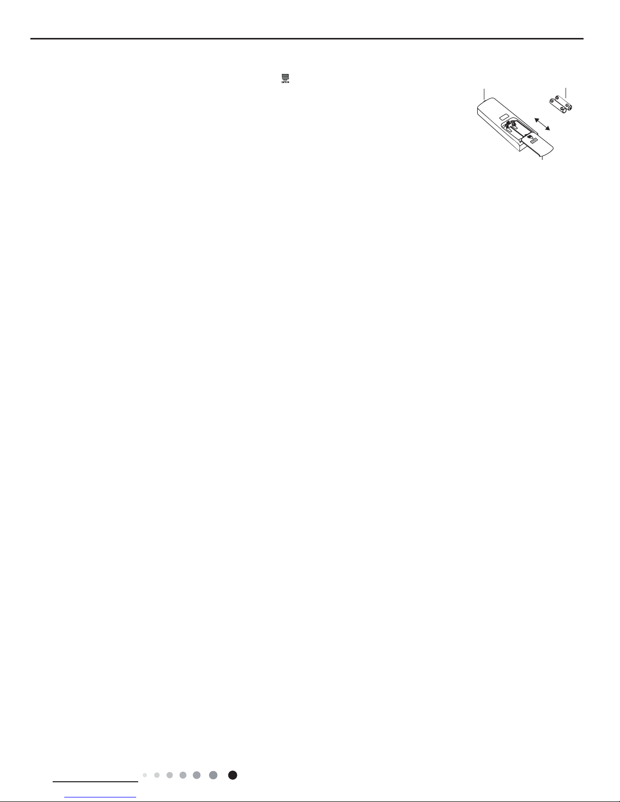
1. Press the back side of remote controller marked with "
", as shown in the g, and then push
out
the cover of battery box along the arrow direction.
2. Replace two 7# (AAA 1.5V) dry batteries, and make sure the position of "+" polar and "-" polar
are correct.
3. Reinstall the cover of battery box.
Note:
signal sender battery
Cover of battery box
remove
reinstall
22
Technical Information
Service Manual
Icon Display on Remote Controller
Send signal
Turbo mode
8ć heating function
Switch temperature displaying type on
the unit’s display
Set time
T-ON /T-OFF
Child lock
Left & right swing
Up & down swing
Sleep mode
Clock
Heat mode
Fan mode
Dry mode
Cool mode
Auto mode
Operation mode
I feel
Quiet
WiFi
This is a general remote controller.Some
models have this function while some
do not. Please refer to the actual models.
{
Set fan speed
(No fan speed. It’s displayed
only after turning it on.)
{
6
3
7
9
10
14
15
13
12
8
11
5
4
2
1
6 button
7 button
8
T-ON / T-OFF button
9 I FEEL button
13
button
14
LIGHT button
15 TEMP button
11
CLOCK button
12
10
1 ON/OFF button
2 MODE button
3 FAN button
4 TURBO button
5
▲
▲/ button
X-FAN function
Healthy mode
Scavenging functions
SLEEP button
WiFi button
8
WiFi
Note:
● After putting through the power, the air conditioner will give out a sound.Operation indictor " " is ON (red indicator, the colou
r
After that, you can operate the airconditioner by using remote controller.
●
Under on status, pressing the button on the remote controller, the signal icon " "
blink once and the air conditioner will give
on the display of remote controller will
out a “de” sound, which means the signal has been sent to the air conditioner.
This is a general use remote controller, it could be used for the air conditioner●
the model doesn't have, if press
with multifunction; For some function, which
the corresponding button on the remote controller that the unit will keep the original running
status.
Press this button to turn on the unit. Press this button again to turn off the unit.
1.ON/OFF button
is different for different models)
6.2 Remote Controller Introduction of YAP1FB2(WiFi)
23
Technical Information
Service Manual
●When selecting auto mode, air conditioner will operate automatically accordin
temperature can’t be adjusted and will not be
to the sensed temperature. Set
/ " "
displayed as well. Press "FAN" button can adjust fan speed. Press " "
button can adjust fan blowing angle.
●After selecting cool mode, air conditioner will operate under cool mode. Cool indicator " " on indoor unit is ON.
▲
"▲" or " " button to adjust set temperature.
Press "FAN" button to adjust fan speed. Press " " / " " button to adjust
fan blowing angle.
●When selecting dry mode, the air conditioner operates at low speed under
Under dry mode, fan speed can’t be adjusted.
mode. Dry indicator " " on indoor unit is ON.
Press " " / " " button to adjust fan blowing angle.
●When selecting fan mode, the air conditioner will only blow fan, no cooling an
indicator is ON. Press "FAN" button
no heating.
All indicators are OFF,Operation
to adjust fan speed. Press" " / " " button to adjust fan blowing angle.
●When selecting heating mode, the air conditioner operates under heat mode
Press "▲" or " " button to adjust set temperature.
Heat indicator " " on indoor unit is ON.
▲
Press "FAN" button to adjust fan speed. Press " " / " " button to adjust fan blowing angle.
(Cooling only unit won’t receive heating mode signal. If
remote controller, press ON/OFF button can’t start up the
setting heat mode with remote controller,setting heat mode with
unit).
2.MODE button
2
Press this button to select your required operation mode.
AUTO COOLDRY FA NHEAT
3
3.FAN button
Pressing thisbuttoncan set fan speed circularly as: auto (AUTO), low( ), medium
( ), high( ).
Auto
Note:
● For preventing cold a r, after starting up heating mode, indoor unit will delay 1~5
depend on indoor ambient temperature).
minutes to blow air (actual delay time is
● Set temperature range from remote controller: 16~3ć(61-86°F);
Fan speed: auto, low speed, low-medium speed,medium speed, medium-high speed,high speed.
● It’s Low fan speed under Dry mode
● Unde AUTO speed, air conditioner will select proper fan speed automatically according to ex-factory setting.
Note:
This function indicates that moisture on evaporator of indoor unit will be blowed after the unit is stopped to avoid mould.
Having set X-FAN function on: After turning off the unit by pressing ON/OFF
few minutes. at low speed. In this
button indoor fan will continue running for a
period, Hold fan speed button for 2s to stop indoor fan directly.
Having set X-FAN function off: After turning off the unit by pressing ON/OFF button, the complete unit will be off directly.
X-FAN function: Hold fan speed button for 2s in COOL or DRY mode, the icon “ ” is
continue operation for a few minutes in order to dry
displayed and the indoor fan will
energization, X-FAN
the indoor unit even though you have turned off the unit. After
OFF is defaulted. X-FAN is not available in AUTO, FAN or HEAT mode.
●
●
●
auto mode)
●When settin T-ON, T-OFF or CLOCK, press "▲" or "
▲
▲
(Refer to CLOCK, T-ON, T-OFF buttons) When setting T-ON,
press "▲" or " " button to adjust time. (Refer to CLOCK,T-ON, T-OFF buttons)
4
4.TURBO button
Under COOL or HEAT mode, press this button to turn to quick COOL or quick
remote controller. Press this button again
HEAT mode. " " icon is displayed on
to exit turbo function and " " icon will disappear.
If start this function,the unit will run at super-highfan speed to cool or heat quickly
preset temp. as soon as possible.
so that the ambient temp. approachs the
▲
5.▲/ button
● Press "▲" or " button once increase or decrease set temperature 1ć(°F).
Holding "▲" or " " button, 2s later, set temperature on remote controller will change quickly. On releasing button after
setting is finished, temperature indica- tor on indoor unit will change accordingly. (Temperature can’t be adjusted under
▲
▲
6
Press this button can select left & right swing angle. Fan blow angle can be selected
circularly as below:
button
6.
Press(This indicator is not available for some models.)
(This indicator is not available for some models.)
(This indicator is not available for some models.)
24
Technical Information
Service Manual
Note:
Press this button continuously more than 2s, the main unit will swing back an●
the button, the unit will stop swinging and
forth from left to right, and then loosen
present position of guide louver will be kept immediately.
● Under swing left and right mode, when the status is switched from o f to , if
will switch to off status directly; if press
press this button again 2s later, status
this button again within 2s, the change of swing status will also depend on the
circulation sequence stated above.
Press this button can select up & down swing angle. Fan blow angle can be selected
circularly as below:
●When selecting " ", air conditioner is blowing fan automaticall . Horizontal
at maximum angle.
louver will automatically swing up & down
●When selecting "
ǃǃ ǃǃ
", air conditioner is blowing fan at fixed
fixed position.
position. Horizontal louver will stop at the
When selecting●
ǃǃ
", air conditioner is blowing fan at fixed angle.
Horizontal louver will send air at the fixed angle.
● Hold " button above 2s to set your required swing angle. When reaching your
required angle, release the button.
Note:
● "
ǃǃ
" may not be available. When air conditioner receives this signal, the
air conditioner will blow fan automatically
.
Press this button continuously more than 2s, the main unit will swing back an●
the button, the unit will stop swinging and
forth from up to down, and then loosen the
present position of guide louver will be kept immediately.
● Under swing up and down mode, w en the status is switched from off to , if
will switch to off status directly; if press
press this button again 2s later, status
no display
(horizontal louvers stops
at current position)
button
7.
this button again within 2s, the change of swing status will also depend on the
circulation sequence stated above.
no display
(stops at current position)
● T-ON button
"T-ON" button can set the time for timer on. After pressing this button, " "
controller blinks. Press "▲" or
icon disappears and the word "ON" on remote
▲
" " button to adjust T-ON setting. After each pressing "▲" or " " button,
▲
T-ON setting will increase or decrease 1min. Hold "▲" or " " button, 2s
▲
your required time.
later, the time will change quickly until reaching
Press "T-ON" to confirm it. The word "ON" will stop blinking. " " icon
T-ON: Under the condition that T-ON is started up,
resumes displaying. Cancel
press "T-ON" button to cancel it.
● T-OFF button
"T-OFF" button can set the time for timer off. After pressing this button," "
icon disappears and the word "OFF" on
remote controller blinks. Press "▲" or
▲
" " button to adjust T-OFF setting.
After each pressing "▲" or " " button,
▲
T-OFF setting will increase or decrease 1min. Hold "▲" or "▲ " button, 2s
your required time.
later, the time will change quickly until reaching
Press "T-OFF" word "OFF" will stop blinking. " " icon resumes displaying.
Cancel T-OFF. Under the condition that T-OFF is started up, press "T-OFF" button to cancel it.
8
8.T-ON / T-OFF button
Note:
● Under on and ff status, you can set T-OFF or T-ON simultaneously.
● Before setting T-ON or T-OFF, please adjust the clock time.
● After starting up T-ON or T-OFF, set the constant circulating valid.
After that, air conditioner will be turned on or turned off according to setting time.
ON/OFF button has no effect on setting. If you don’t need this function, please use remote controller to cancel it.
9.I FEEL button
Press this button to start I FEEL function and " " will be displayed on the remote
remote controller will send the detected
controller. After this function is set, the
ambient temperature to the controller and the unit will automatically adjust the
indoor temperature according to the detected temperature. Press this button again
disappear.
to close I FEEL function and " " will
● Please put the remote controller near ser when this function is set. Do not put
high temperature or low temperature in
the remote controller near the object of
turned on, the remote controller should be put within the area where indoor unit can receive the signal sent by the remote
controller.
order to avoid detecting inaccurate ambient temperature.When I FEEL function is
25
Technical Information
Service Manual
Press " WiFi " button to turn on or turn off WiFi function. When WiFi function is turned
on, the " WiFi " icon will be displayed on remote controller; Under status of unit off,
on, the " WiFi " icon will be displayed
simultaneously for 1s, WiFi module will restore to
press "MODE" and " WiFi " buttons
factory default setting.
● This function is only available for some models.
12.WiFi button
13.
Press this button to achieve the on and off of healthy and scavenging functions in
LCD displays " ". Press the button for the second time to start healthy and
scavenging functions simultaneously; LCD displays " " and " ". Press this
scavenging functions simultaneo
button for the third time to quit healthy and
usly.
Press the button for the fourth t ime to start healthy function; LCD display " ".
Press this button again to repeat the operation above.
This function is applicable to partial of models●
button
Press this button to set clock time. " " icon on remote controller will blink. Press
▲
"▲" or " " button within 5s to set clock
time. Each pressing of "▲" or " " button,
▲
clock time will increase or decrease 1 minute. If hold "▲" or " " button, 2s later
▲
time will change quickly. Release this button when reaching your required time.
Note:
Clock time adopts 24-hour mode●
● The interval between two operation can’t exceeds 5s. Otherwise, remote contro-
ller will quit setting status. Operation for
T-ON/T-OFF is the same.
10.CLOCK button
11.SLEEP button
Under COOL, or HEAT mode, press this button to start up sleep function.
" " icon is displayed on remote controller. Press this button again to cancel sleep
.After powered on, Sleep Off is defaulted. After
function and " " icon will disappear.
the unit is turned off, the Sleep function is canceled.
In this mode, the time of time can be adjusted. Under Fan
DRY and Auto modes, this function is not available.
14.LIGHT button
Press this button to turn of
f display light on indoor unit. " " icon on remote
to turn on display light. " " icon is
controller disappears. Press this button again
displayed.
15.TEMP button
By pressing this button, you can see indoor set temperature, indoor ambient temp on indoor unit’
s display. The setting on
erature or outdoor ambient temperature
remote controlleris selected circularly as below:
no display
●When selecting " " or no display with remote controllr, temperature indicator on indoor unit displays set temperature.
●When selecting " " with remote controllr, temperature indicator on indoor unit displays indoor ambient temperature.
●When selecting " " with remote controllr, temperature indicator on indoor unit displays outdoor ambient temperature.
Note:
●
Outdoor temperature display is not available for some models. At that time, indoor
displays indoor set temperature.
unit receives " " signal, while it
●I’s defaulted to display set temperature when turning on the unit.There is nodisplay in the remote controller.
● Only for the models whose indoor unit has dual-8 disply.
●When selecting displaying of indoor or outdoor ambient temperature, indoor
temperature and automatically turn
temperature indicator displays corresponding
Energy-saving function
Under cooling mode, press "TEMP" and " CLOCK" buttons simultaneously to
When energy-saving function is started
start up or turn off energy-saving function.
up, "SE" will be shown on remote controller, and air conditioner will adjust the set
Function introduction for combination buttons
26
Technical Information
Service Manual
Note:
Under energy-saving function, fan speed is defaulted at auto speed and it can’● be adjusted.
●
Under energy-saving function, set temperature can’t be adjusted. Press "TURBO"
send signal.
button and the remote controller won’t
● Sleep function and energy-saving function can’t operate at the same time. I
cooling mode, press sleep button will
energy-saving function has been set under
cancel energy-saving function. If sleep function has been set under cooling
mode, start up the energy-saving function will cancel sleep function.
8ć heating function
Under heating mode, press "TEMP" and "CLOCK" buttons simultaneously to start
up or turn off 8
ć
When this function is started up, " " and "8
heating function.
ć
"
heating status
will be shown on remote controller, and the air conditioner keep the
at 8ć. Press "TEMP" and "CLOCK" buttons simultaneously again to exit 8
ć
heating function.
Note:
● Under ć heating function, fan speed is defaulted at auto speed and it can’t be adjusted.
● Under ć heating function, set temperature can’t be adjusted. Press
"
TURBO
"
send signal.
button and the remote controller won’t
● Sleep function and ć heating function can’t operate at the same time. If 8
ć
heating function has been set under cooling mode, press sleep button will cancel
heating function has been set under cooling
has been set under cooling mode, start up
8ć heating function. If sleep function
the 8ć heating function will cancel sleep function.
● Under temperature display, the remote controller will display 46 heating.
Child lock function
▲
Press "▲" and " " simultaneously to turn on or turn off child lock function. When
displayed on remote controller. If you operate
child lock function is on, " " icon is
the remote controller
, the " " icon will blink three times without sending signal to
the unit.
Temperature display switchover function
Under OFF status, press " " and "MODE▲" buttons simultaneously to switch temp- erature display between ć and
.
1.
After putting through the power, press "ON/OFF" button on remote controller to turn on the air conditioner.
2.
Press "MODE" button to select your required mode: AUTO, COOL, DRY, FAN, HEAT.
3.
Press "▲" or " " button to set your required temperature. (Temperature can’t be adjusted under auto mode).
4.
Press "FAN" button to set your required fan speed: auto, low speed, low-medium speed,medium speed, medium-high
speed,high speed.
Operation guide
▲
Replacement of batteries in remote controller
Note:
5.
Press " " button to select fan blowing angle.
1. Lift the cover along the direction of arrow (as shown in Fig 1ǐ).
2. Take out the original batteries (as shown in Fig 1 Ǒ).
3. Place two 7# (AAA 1.5V) dry batteries, and make sure the position of “+” polar and “-” polar is correct (as shown in Fig 2
ǒ).
4. Reinstall the cover (as shown in Fig 2Ǔ).
Fig.1
Fig.2
● During operation, point the remote co ntrol signal sender at the receiving window on indoor unit.
● The distance between signal sender and receiving window should be no more than 8m, and there should be no obstacles
between them.
● Signal may be interfered easily in the room where there is fluorescent lamp
be close to indoor unit during
or wireless telephone; remote controller should
operation.
● Replace new batteries of the same model when replacement is required.
● When you don’t use remote controller for a long time, please take out the batteries.
● If the display on remote controller is fuzzy or there ’s no display, please replace batteries.
temperature automatically according to ex-factory setting to reach to the best
energy-saving effect. Press "TEMP" and "CLOCK" buttons simultaneously again to
energy-saving effect. Press "TEMP" and
exit energy-saving function.

27
Technical Information
Service Manual
6.3 Brief Description of Modes and Functions
1. Temperature Parameters
◆
Indoor preset temperature (Tpreset)
◆
Indoor ambient temperature (Tamb.)
2. Basic Functions
Once energized, in no case should the compressor be restarted within less than 3 minutes. In the situation that memory function
is available, for the rst energization, if the compressor is at stop before de-energization, the compressor will be started without a
3-minute lag; if the compressor is in operation before de-energization, the compressor will be started with a 3-minute lag; and once
started, the compressor will not be stopped within 6 minutes regardless of changes in room temperature;
(1) Cooling Mode
①
Working conditions and process of cooling
Cooling conditions and process(09k)
a. When Tamb.≥Tpreset the unit starts cooling. In this case, the IDU fan motor, ODU fan motor and compressor run, and the IDU fan
motor runs at set speed;
b. When Tamb.=Tpreset-3℃, the compressor continuously operates below the frequency of 15Hz (not including 15Hz) for 15mins. If
Tamb.=Tset-3℃ still keeps the same, the compressor stops operation;
c. When Tamb.≤Tpreset-4℃, the compressor stops operation; ODU fan motor stops operation with a delay of 30s and IDU fan motor
operates at set speed;
d. When Tpreset-2℃<Tamb.<Tset, the unit will maintain its previous running status.
Cooling conditions and process(12k)
a.When Tamb.+Tindoor supplementary≥Tpreset, the unit starts cooling. In this case, the IDU fan motor, ODU fan motor and
compressor run, and the IDU fan motor runs at set speed;
b. When Tamb.+Tindoor supplementary≤Tpreset-2℃, the compressor stops operation; ODU fan motor stops operation with a delay
of 30s and IDU fan motor operates at set speed;
c.When Tpreset-2℃<Tindoor amb.+Tindoor supplementary<Tpreset, the unit will maintain its previous running status.
Under this mode, the four-way valve will be de-energized and temperature can be set within a range from 16 to 30
o
C.
If the compressor is shut down for some reason, the indoor fan and the swing device will operate at original state.
②
Protection
◆
Antifreeze protection
Under cooling and dehumidifying mode, 6 minutes after the compressor is started:
If T evap≤2
o
C, the compressor will operate at reduced frequency.
If T evap≤-1
o
Cis detected for durative 3 minutes, the compressor will stop, and after 30 seconds, the outdoor fan will stop; and under
cooling mode, the indoor fan and the swing motor will remain at the original state.
If T evap. ≥10
o
Cand the compressor has remained at OFF for at least 3 minutes, the compressor will resume its original operation
state.
◆
Total current up and frequency down protection
If I
total
≤6, frequency rise will be allowed; if I
total
≥7, frequency rise will not be allowed; if I
total
≥8, the compressor will run at reduced
frequency; and if I
total
≥9, the compressor will stop and the outdoor fan will stop with a time lag of 30s.
(2) Dehumidifying Mode
①
Working conditions and process of dehumidifying
If Tamb>Tpreset, the unit will enter cooling and dehumidifying mode, in which case the compressor and the outdoor fan will operate
and the indoor fan will run at low speed.
If Tpreset -2
o
C≤Tamb≤Tpreset, the compressor remains at its original operation state.
If Tamb.< Tpreset -2
o
C, the compressor will stop, the outdoor fan will stop with a time lag of 30s, and the indoor fan will operate at
low speed.
②
Protection
Protection is the same as that under the cooling mode.
(3) Heating Mode
 Loading...