

Gree GWH12MA-K3DNA3L, GWH09MA-K3DNB7L, GWH09MA-K3DNA4L, GWH12MA-K3DNB3L, GWH12MA-K3DNB7L Service Manual
...
GREE ELECTRIC APPLIANCES,INC.OF ZHUHAI
Change for Life
Service Manual
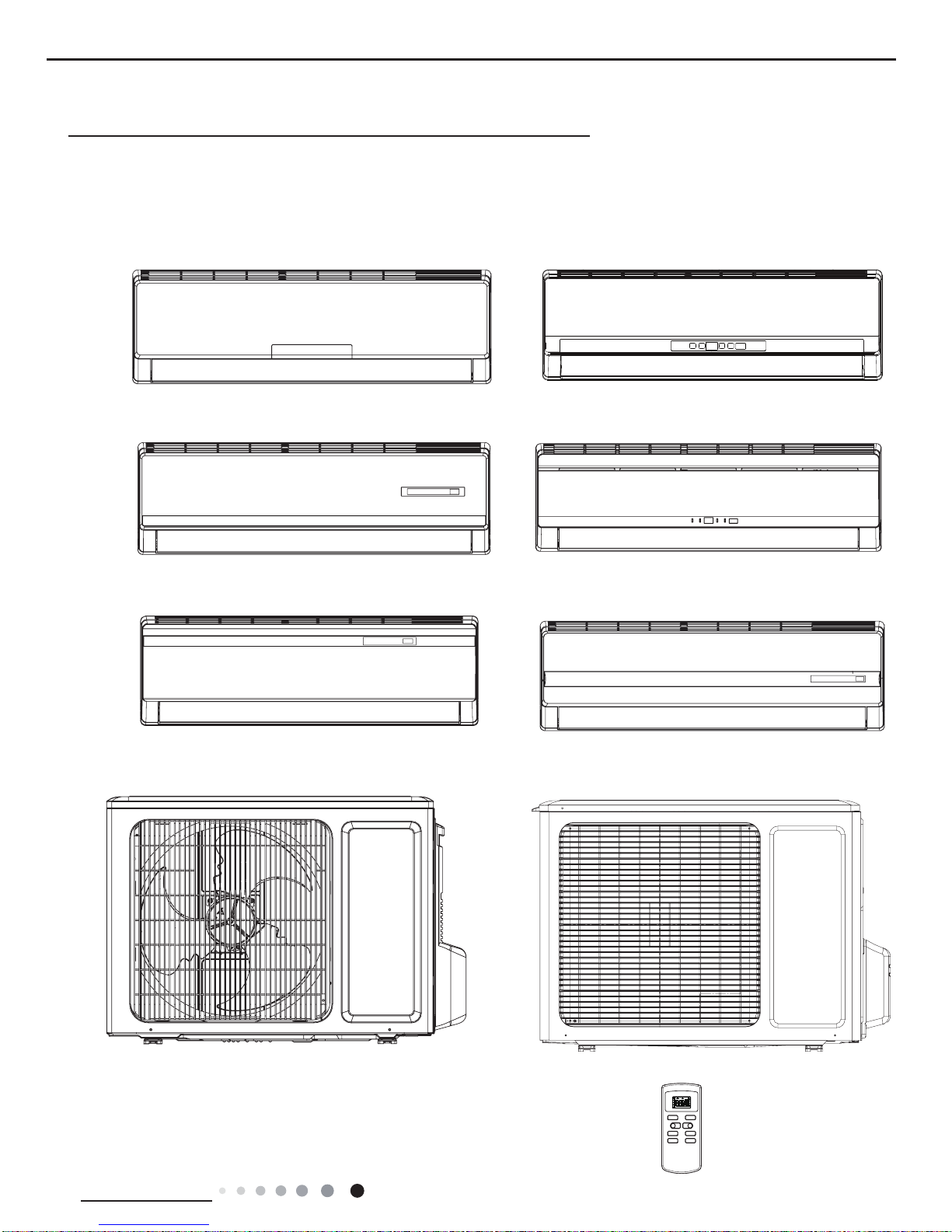
GWH09MA-K3DNA3L
GWH09MA-K3DNA4L
GWH09MA-K3DNB7L
GWH09MA-K3DND3L
GWH09MA-K3DNC9L
GWH09MA-K3DNB3L
GWH12MA-K3DNA3L
GWH12MA-K3DNB3L
Models:
GWH12MA-K3DNB7L
GWH12MA-K3DNC9L
GWH12MA-K3DND3L
(Refrigerant:R410A)

Service Manual
Table of Contents
Table of Contents
Part
Ⅰ
: Technical Information
........................................................................ 1
1. Summary
........................................................................................................................ 1
2. Specications
............................................................................................................ 2
2.1 Specication Sheet ............................................................................................................. 2
2.2 Operation Characteristic Curve .......................................................................................... 4
2.3 Capacity Variation Ratio According to Temperature ........................................................... 4
2.4 Cooling and Heating Data Sheet in Rated Frequency ....................................................... 5
2.5 Noise Curve ........................................................................................................................ 5
3. Outline Dimension Diagram
.......................................................................... 6
3.1 Indoor Unit .......................................................................................................................... 6
3.2 Outdoor Unit ....................................................................................................................... 7
4. Refrigerant System Diagram
........................................................................ 8
5. Electrical Part
............................................................................................................. 9
5.1 Wiring Diagram ................................................................................................................... 9
5.2 PCB Printed Diagram ........................................................................................................11
6. Function and Control
........................................................................................ 13
6.1 Remote Controller Introduction ........................................................................................ 13
6.2 Brief Description of Modes and Functions ........................................................................ 16
Part
Ⅱ
: Installation and Maintenance
................................................... 21
7. Notes for Installation and Maintenance
............................................ 21
8. Installation
.................................................................................................................. 23
8.1 Installation Dimension Diagram ........................................................................................ 23
8.2 Installation Parts-checking .............................................................................................. 25
8.3 Selection of Installation Location ...................................................................................... 25
8.4 Electric Connection Requirement ..................................................................................... 25
8.5 Installation of Indoor Unit .................................................................................................. 25
8.6 Installation of Outdoor Unit ............................................................................................... 28
8.7 Vacuum Pumping and Leak Detection ............................................................................. 29
8.8 Check after Installation and Test Operation ..................................................................... 29

Service Manual
9. Maintenance
.................................................................................................................30
9.1 Malfunction Analysis ............................................................................................................30
9.2 Flashing LED of Indoor/Outdoor Unit and Primary Judgement ........................................... 34
9.3 How to Check Simply the Main Part ....................................................................................43
10. Exploded View and Parts List
................................................................... 56
10.1 Indoor Unit .........................................................................................................................56
10.2 Outdoor Unit ...................................................................................................................... 63
11. Removal Procedure
............................................................................................ 67
11.1 Removal Procedure of Indoor Unit ....................................................................................67
11.2 Removal Procedure of Outdoor Unit .................................................................................72
Appendix:
.............................................................................................................................81
Appendix 1: Reference Sheet of Celsius and Fahrenheit .........................................................81
Appendix 2: Conguration of Connection Pipe ..........................................................................81
Appendix 3: Pipe Expanding Method ........................................................................................82
Appendix 4: List of Resistance for Temperature Sensor ...........................................................83
1
Technical Information
Service Manual
1. Summary
Part
Ⅰ
: Technical Information
Indoor Unit:
GWH09MA-K3DNA3L/I
GWH12MA-K3DNA3L/I
GWH09MA-K3DNB7L/I
GWH12MA-K3DNB7L/I
GWH12MA-K3DND3L/I
GWH09MA-K3DND3L/I
GWH09MA-K3DNB3L/I
GWH12MA-K3DNB3L/I
GWH12MA-K3DNC9L/I
GWH09MA-K3DNC9L/I
GWH09MA-K3DNA4L/I
Outdoor Unit:
GWH09MA-K3DNA3L/O
GWH12MA-K3DNA3L/O
Remote Controller:
YX1F
ON/OFF MODE
FAN SWING
SLEEP TIMER
+
-
AUTO
COOL
DRY
FAN
HEAT
T-ONT-OFF
SWING
SLEEP
LOCK
SPEED
2
Technical Information
Service Manual
2. Specications
2.1 Specication Sheet
Model
GWH09MA-K3DNA3L GWH09MA-K3DNA4L
GWH09MA-K3DNB7L GWH09MA-K3DND3L
GWH09MA-K3DNC9L GWH09MA-K3DNB3L
GWH12MA-K3DNA3L
GWH12MA-K3DNB7L GWH12MA-K3DNC9L
GWH12MA-K3DND3L GWH12MA-K3DNB3L
Product Code
CB171010400 CB161007300
CB164002600 CB405004100
CB145005700 CB163007000
CB171010300
CB164002700 CB145005600
CB405004000 CB163007100
Power
Supply
Rated Voltage V~ 220-240 220-240
Rated Frequency Hz 50 50
Phases 1 1
Power Supply Mode Outdoor Outdoor
Cooling Capacity(Min~Max) W 2500(600~2800) 3200(600~3500)
Heating Capacity(Min~Max) W 2750(600~3000) 3400(600~3800)
Cooling Power Input(Min~Max) W 800(120~1300) 1020(120~1400)
Heating Power Input(Min~Max) W 780(120~1400) 995(120~1500)
Cooling Current Input A 3.6 4.5
Heating Current Input A 3.5 4.4
Rated Input W 1400 1500
Rated Current A 6.7 7.2
Air Flow Volume(SH/H/M/L/SL) m3/h 500/400/300/250/- 500/400/300/250/Dehumidifying Volume L/h 0.8 1.4
EER W/W 3.13 3.14
COP W/W 3.53 3.42
SEER 5.8 6.1
HSPF / /
Application Area m
2
12-18 15-22
Indoor
Unit
Indoor Unit Model
GWH09MA-K3DNA3L/I GWH09MA-K3DNA4L/I
GWH09MA-K3DNB7L/I GWH09MA-K3DND3L/I
GWH09MA-K3DNC9L/I GWH09MA-K3DNB3L/I
GWH12MA-K3DNA3L/I
GWH12MA-K3DNB7L/I GWH12MA-K3DNC9L/I
GWH12MA-K3DND3L/I GWH12MA-K3DNB3L/I
Indoor Unit Product Code
CB171N10400 CB161N07300
CB164N02600 CB405N04100
CB145N05700 CB163N07000
CB171N10300
CB164N02700 CB145N05600
CB405N04000 CB163N07100
Fan Type Cross-ow Cross-ow
Fan Diameter Length(DXL) mm Φ85X596 Φ85X596
Cooling Speed(SH/H/M/L/SL) r/min 1320/1100/920/730/- 1320/1100/920/730/Heating Speed(SH/H/M/L/SL) r/min 1350/1200/1100/1000/- 1350/1200/1100/1000/Fan Motor Power Output W 10 10
Fan Motor RLA A 0.15 0.15
Fan Motor Capacitor μF 1 1
Evaporator Form Aluminum Fin-copper Tube Aluminum Fin-copper Tube
Evaporator Pipe Diameter mm Φ7 Φ7
Evaporator Row-n Gap mm 2-1.4 2-1.4
Evaporator Coil
Length(LXDXW)
mm 592X25.4X266.7 592X25.4X266.7
Swing Motor Model MP24AA MP24AA
Swing Motor Power Output W 1.5 1.5
Fuse Current A 3.15 3.15
Sound Pressure Level
(SH/H/M/L/SL)
dB (A) 38/34/31/28/- 39/34/31/28/-
Sound Power Level
(SH/H/M/L/SL)
dB (A) 50/46/43/40/- 53/47/43/40/-
Dimension(WXHXD) mm 790X265X174 790X265X174
Dimension of Carton
Box(LXWXH)
mm 870X248X355 870X248X355
Dimension of
Package(LXWXH)
mm 873X251X370 873X251X370
Net Weight kg 9 9
Gross Weight kg 10.5 10.5
3
Technical Information
Service Manual
Outdoor
Unit
Model of Outdoor Unit GWH09MA-K3DNA3L/O GWH12MA-K3DNA3L/O
Product Code of Outdoor Unit CB171W10400 CB171W10300
Compressor Manufacturer/Trademark
ZHUHAI LANDA COMPRESSOR
CO., LTD
ZHUHAI GREE DAIKIN DEVICE
CO., LTD
Compressor Model QXA-A091zE190A 1GDY23AXD
Compressor Oil 68EP FVC50K
Compressor Type Rotary Rotary
L.R.A. A 16.5 16.5
Compressor RLA A 4.5 4
Compressor Power Input W 942 845
Overload Protector 1NT11L-6233 1GDY23AXD-05
Throttling Method Capillary Capillary
Operation temp
o
C 16~30 16~30
Ambient temp (cooling)
o
C -15~48 -15~48
Ambient temp (heating)
o
C -15~24 -15~24
Condenser Form Aluminum Fin-copper Tube Aluminum Fin-copper Tube
Pipe Diameter mm Φ7 Φ7.94
Rows-n Gap mm 1-1.4 1-1.4
Coil Length (LXDXW) mm 692X19.05X506 731X19.05X550
Fan Motor Speed rpm 900/600 900/600
Output of Fan Motor W 30 30
Fan Motor RLA A 0.4 0.4
Fan Motor Capacitor μF / /
Air Flow Volume of Outdoor Unit m3/h 1600 2200
Fan Type Axial-ow Axial-ow
Fan Diameter mm Φ400 Φ438
Defrosting Method Automatic Defrosting Automatic Defrosting
Climate Type T1 T1
Isolation I I
Moisture Protection IP24 IP24
Permissible Excessive Operating
Pressure for the Discharge Side
MPa 4.3 4.3
Permissible Excessive Operating
Pressure for the Suction Side
MPa 2.5 2.5
Sound Pressure Level (H/M/L) dB (A) 50/-/- 51/-/-
Sound Power Level (H/M/L) dB (A) 60/-/- 63/-/-
Dimension (WXHXD) mm 776X540X320 842X596X320
Dimension of Carton Box (LXWXH) mm 820X355X580 878X360X630
Dimension of Package (LXWXH) mm 823X358X595 881X363X645
Net Weight kg 27 31
Gross Weight kg 29.5 34
Refrigerant R410A R410A
Refrigerant Charge kg 0.7 0.85
Connection
Pipe
Length m 5 5
Gas Additional Charge g/m 20 20
Outer Diameter Liquid Pipe mm Φ6 Φ6
Outer Diameter Gas Pipe mm Φ9.52 Φ12
Max Distance Height m 10 10
Max Distance Length m 15 20
Note: The connection pipe applies metric diameter.
The above data is subject to change without notice; please refer to the nameplate of the unit.
4
Technical Information
Service Manual
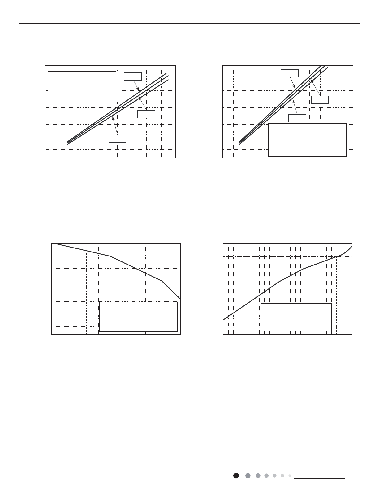
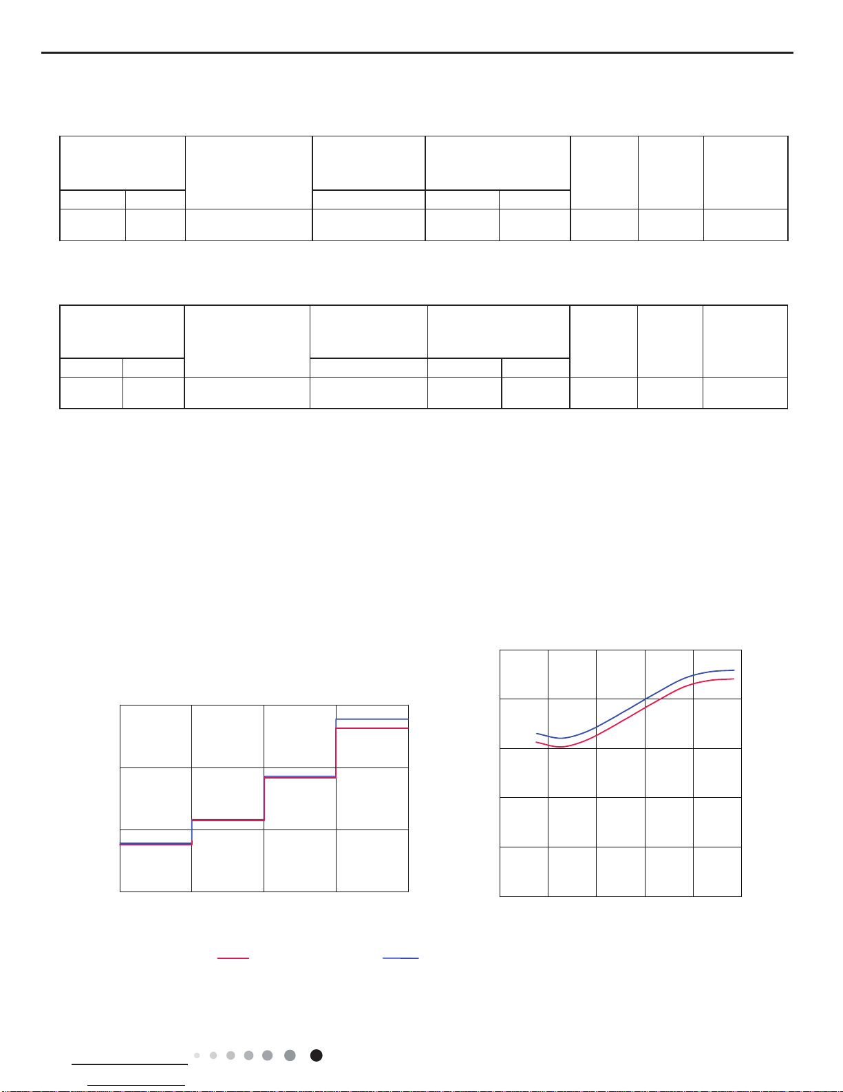
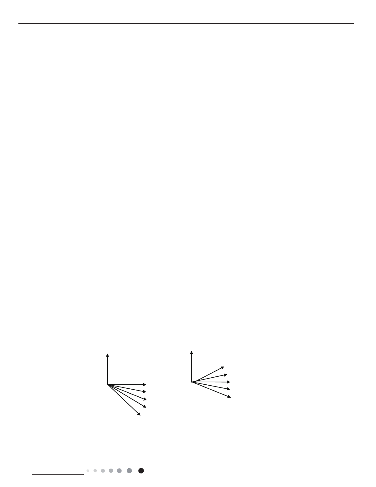
2.2 Operation Characteristic Curve
2.3 Capacity Variation Ratio According to Temperature
Cooling Heating
0 10 20 30 40 50 60 70 90 0 10 20 30 40 50 60 70 80 90 100 120110
80
11
10
9
8
7
6
5
4
3
2
1
0
11
10
9
8
7
6
5
4
3
2
1
0
220V
230V
240V
220V
230V
240V
Current (A)
Current (A)
Conditions
Indoor:DB27°C/WB19°C
Outdoor:DB35°C/WB24°C
Indoor air flow:Super High
Pipe length:5m
Conditions
Indoor:DB20°C/WB15°C
Outdoor:DB7°C/WB6°C
Indoor air flow:Super High
Pipe length:5m
Compressor speed (rps) Compressor speed (rps)
Cooling Heating
32 33 34 35 36 37 38 39 43
40 41 42
100
105
95
90
85
80
75
70
65
60
55
50
Conditions
Indoor:DB27°C/WB19°C
Indoor air flow:Super High
Pipe length:5m
Outdoor temp.(°C)
Capacity ratio (%)
–15 –10 –5
110
100
90
80
70
60
50
40
0 5 7 10
Conditions
Indoor:DB20°C/WB15°C
Indoor air flow:Super High
Pipe length:5m
Outdoor temp.(°C)
Capacity ratio (%)
5
Technical Information
Service Manual
2.4 Cooling and Heating Data Sheet in Rated Frequency
Instruction:
T1: Inlet and outlet pipe temperature of evaporator
T2: Inlet and outlet pipe temperature of condenser
P: Pressure at the side of big valve
Connection pipe length: 5 m.
Cooling:
Heating:
Rated cooling
condition(oC) (DB/WB)
Model
Pressure of gas pipe
connecting indoor
and outdoor unit
Inlet and outlet pipe
temperature of heat
exchanger
Fan speed
of indoor
unit
Fan speed
of outdoor
unit
Compressor
revolution (rps)
Indoor Outdoor P (MPa) T1 (oC) T2 (oC)
27/19 35/24 09/12K 0.8 ~ 1.1 11 to 14 38 to 41 Super High High 60
Rated heating
condition(oC) (DB/WB)
Model
Pressure of gas pipe
connecting indoor and
outdoor unit
Inlet and outlet pipe
temperature of heat
exchanger
Fan speed
of indoor
unit
Fan speed
of outdoor
unit
Compressor
revolution (rps)
Indoor Outdoor P (MPa) T1 (°C) T2 (°C)
20/15 7/6 09/12K 2.8 ~ 3.2 38 to 41 2 to 5 Super High High 66
2.5 Noise Curve
Indoor side noise
Outdoor side noise
Indoor fan motor rotating speed
Compressor frequency/Hz
Low Middle High Supper High
Noise/dB(A)
Noise/dB(A)
70
60
40
30
35
25
50
40
30
0 20 40 60 80 100
20
09K 12K
6
Technical Information
Service Manual
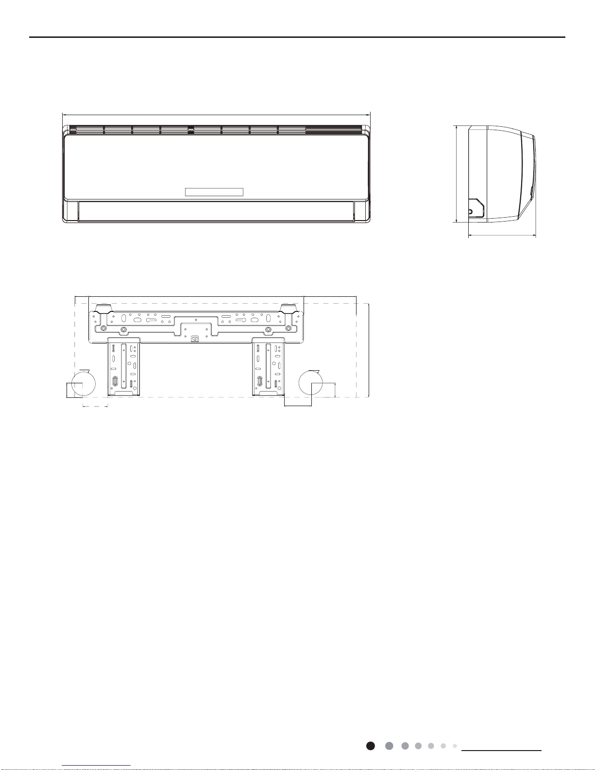
3. Outline Dimension Diagram
3.1 Indoor Unit
Unit:mm
174
790
71
40
76
40
605
37
148
Φ55
Φ55
265
265
7
Technical Information
Service Manual
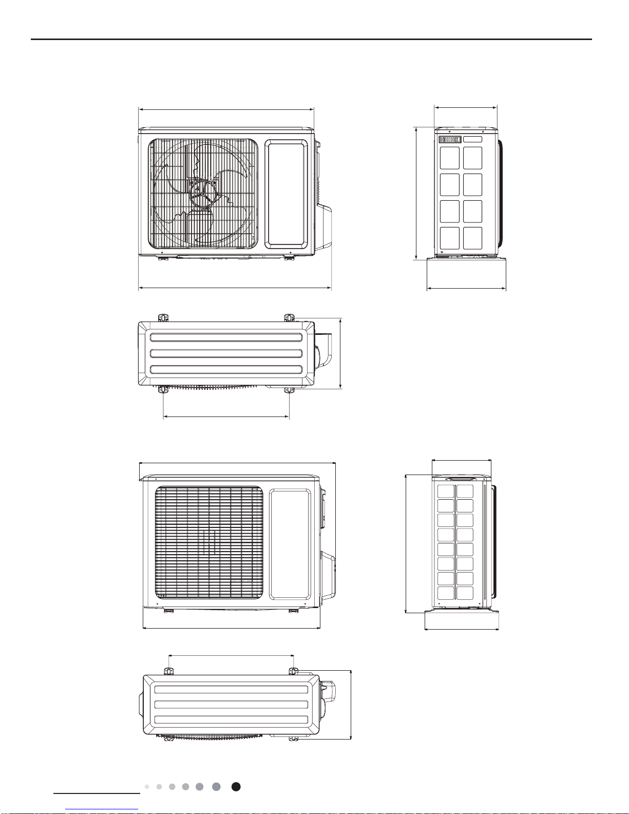
714 257
776
510
540
286
320
540
297
842
320
596
257
763
3.2 Outdoor Unit
12K
09K
Unit:mm
Unit:mm
8
Technical Information
Service Manual
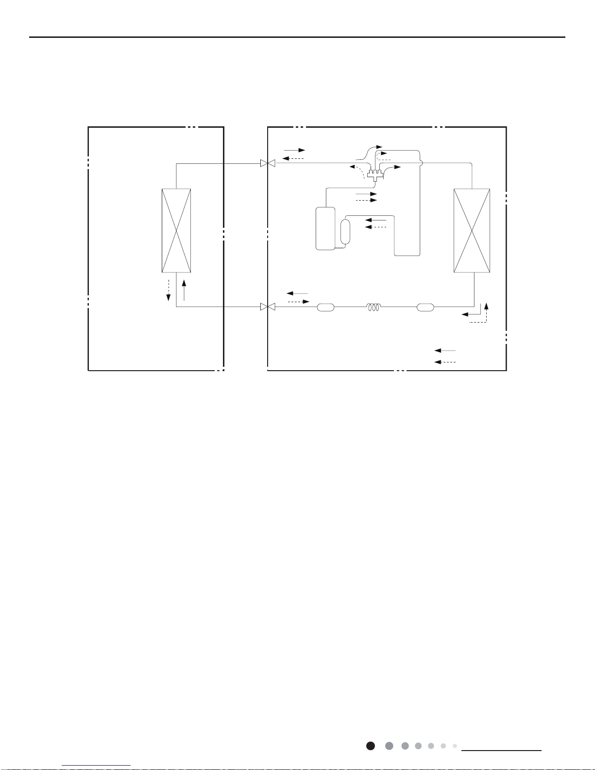
4. Refrigerant System Diagram
Indoor unit
Outdoor unit
COOLING
HEATING
4-Way valve
Discharge
Suction
Heat
exchanger
(evaporator)
Heat
exchanger
(condenser)
Valve
Valve
Liquid pipe
side
Gas pipe
side
Strainer Capillary Strainer
Accumlator
Compressor
Connection pipe specication:
Liquid pipe:1/4" (6mm)
Gas pipe:3/8" (9.52mm)09K
Gas pipe:1/2" (12mm)12K
Cooling and heating model
9
Technical Information
Service Manual
5. Electrical Part
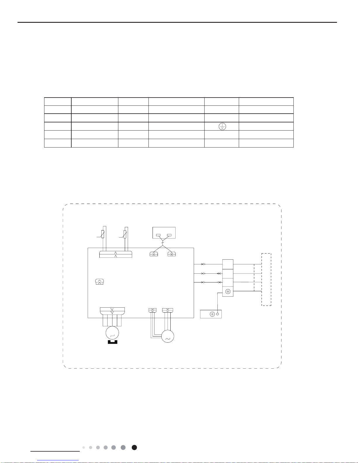
5.1 Wiring Diagram
● Indoor Unit
●Instruction
Symbol Symbol Color Symbol Symbol Color Symbol Name
WH White GN Green CAP Jumper cap
YE Yellow BN Brown COMP Compressor
RD Red BU Blue Grounding wire
YEGN Yellow/Green BK Black / /
VT Violet OG Orange / /
Note: Jumper cap is used to determine fan speed and the swing angle of horizontal lover for this model.
SWING-UD
M2
AC-L
BN
BK
BU
EVAPORATOR
CAP
PE
YEGN
JUMP
DISP2
SWING
N
COM-OUT
BK
BN
3
XT
2
N(1)
BU
YEGN
DISP1
DISPLAY BOARD
TERMINAL
RECEIVER AND
MOTOR
BLOCK
M1
PGPGF
FAN
MOTOR
OUTDOOR UNIT
θ
RT1
RT2
TUBE TEMP.
SENSOR
T-SENSOR
θ
SENSOR
ROOM TEMP.
AP2
PRINTED CIRCUIT BOARD
AP1
CONNECTING
CABLE
10
Technical Information
Service Manual
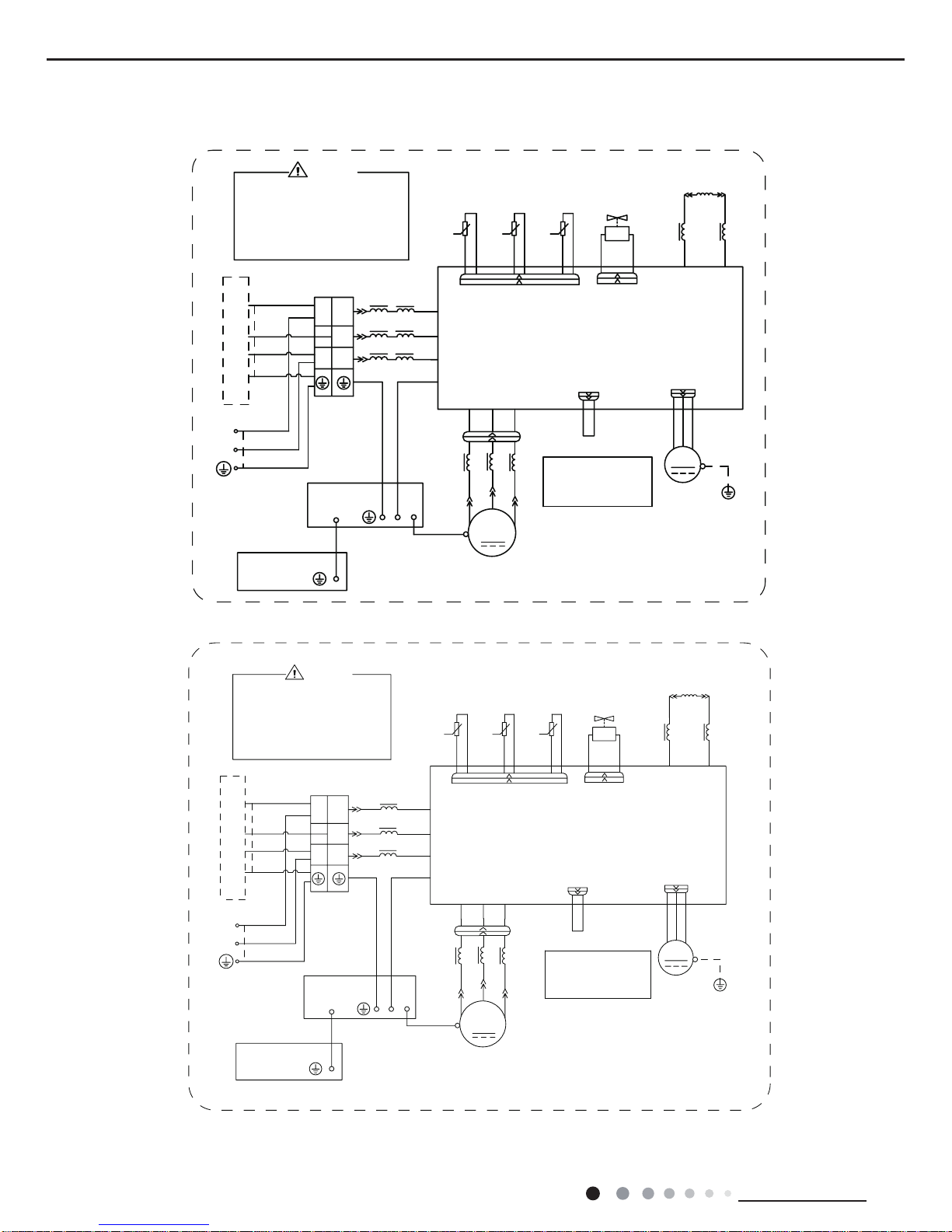
These wiring diagrams are subject to change without notice; please refer to the one supplied with the unit.
● Outdoor Unit
BN
BK
BU
L4
L1
L4
L3
L3
RING
MAGNETIC
PE
L3
BU
V
RD
YE
LX1-1
LX1-2
TERMINAL
N
L
N(1)
2
3
L
N
CN2
OFAN
W
V
U
AP:Main Board
N
AC-L
COMU
PE
L2
L2
REACTOR
L
BU
BN
TEMP.
SENSOR
TEMP.
SENSOR
TEMP.
RT3
RT2
RT1
SENSOR
θ
4YV
4-WAY
4WAY
MAGNETIC
RING
(20k)
(15k)
(50k)
MAGNETIC
RING
X1
MID.ISOLATION
SHEET
YEGN
PE
PE
YEGN
YEGN
YEGN
YEGN(GN)
VALVE
OUTTUBE
OUTROOM
EXHAUST
BLOCK
BU
BK
BN
BU(WH)
BN(BK)
VT
VT
the risk of electric shock!
Please don't touch any
terminal when the machine
is running ,stopping or has
been powered off for less
than 30 minutes to prevent
WARNING
BU
YE
RD
θ
θ
YEGN
RD
W
U
COMP.
COMP
WIRE
XT
POWER
FAN
M
PE
PE
OVC-COMP
NOTE:
Motor
only applies to the
iron shell motor.
ground
ELECTRICAL
BOX
YEGN
MOTOR
INDOOR UNIT
%1
%.
%8
/
/
/
/
/
5,1*
0$*1(7,&
/
3(
/
%8
9
5'
<(
/;
/;
7(50,1$/
1
/
1
/
1
&1
2)$1
:
9
8
$30DLQ%RDUG
/
1
$&/
&208
3(
/
/
5($&725
/
%8
%1
7(03
6(1625
7(03
6(1625
7(03
57
57
57
6(1625
©
<9
:$<
:$<
0$*1(7,&
5,1*
N
N
N
0$*1(7,&
5,1*
;
0,',62/$7,21
6+((7
<(*1
3(
3(
<(*1
<(*1
<(*1
<(*1*1
9$/9(
28778%(
2875220
(;+$867
%/2&.
%8
%.
%1
%8:+
%1%.
97
97
WKHULVNRIHOHFWULFVKRFN
3OHDVHGRQWWRXFKDQ\
WHUPLQDOZKHQWKHPDFKLQH
LVUXQQLQJVWRSSLQJRUKDV
EHHQSRZHUHGRIIIRUOHVV
WKDQPLQXWHVWRSUHYHQW
:$51,1*
%8
<(
5'
©
©
/
<(*1
5'
:
8
&203
&203
:,5(
;7
32:(5
)$1
0
3(
3(
29&&203
127(
0RWRU
RQO\DSSOLHVWRWKH
LURQVKHOOPRWRU
JURXQG
(/(&75,&$/
%2;
<(*1
02725
,1'22581,7
12K
09K
11
Technical Information
Service Manual
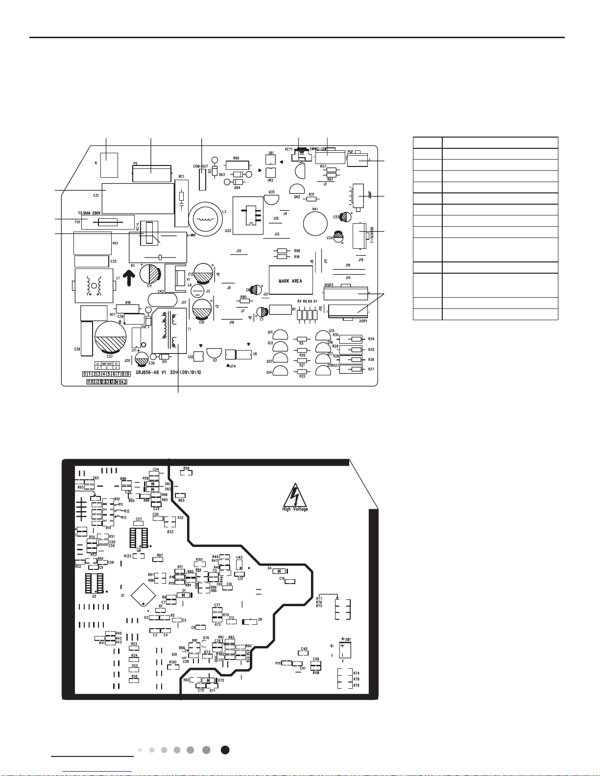
5.2 PCB Printed Diagram
No. Name
1 Live wire interface
2 Fuse
3 Fan capacitor
4 Neutral wire interface
5 Fan motor interface of PG
6 Communication interface
7 Auto button
8 up&down swing interface
9
Interface of PG feedback
interface
10 Jumper cap
11
Interface of temperature
sensor
12 display interface
13 High Frequency Transformer
● Top view
● Bottom view
Indoor Unit
1
2
3
4 5 6 7 8
9
10
11
12
13
12
Technical Information
Service Manual
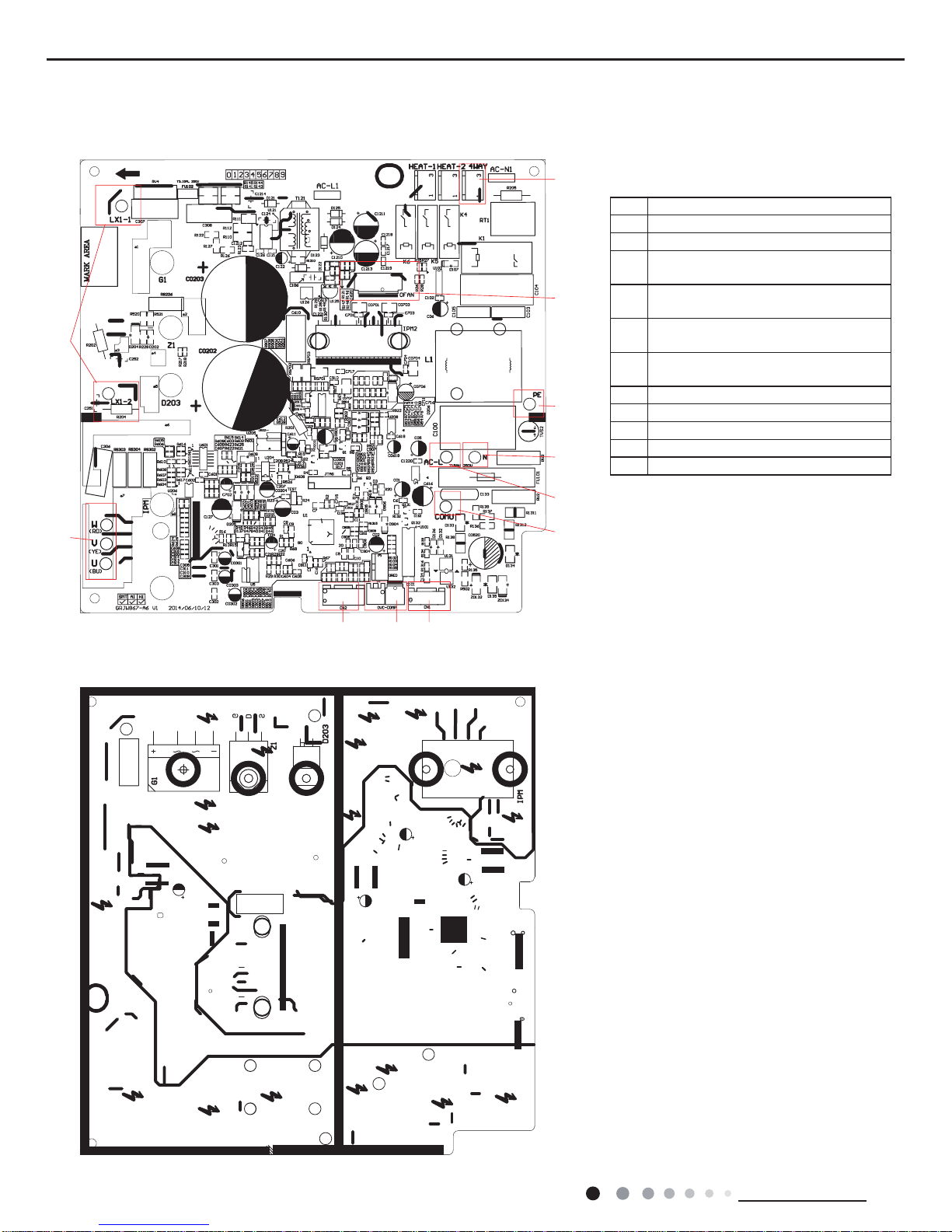
Outdoor Unit
● Top view
● Bottom view
1
2
3 4 11
5
6
7
8
9
10
No. Name
1 Reactor wiring terminal
2 Compressor wiring terminal
3
Terminal of outdoor unit temperature
sensor
4
Compressor overload protection
terminal
5
Terminal with indoor unit communication
wire
6
Terminal of power supply live wire
terminal
7 Terminal of power supply neutral wire
8 Interface of earthing wire
9 Terminal of outdoor fan
10 Interface of 4-way valve
11 Terminal of electronic expansion valve
13
Technical Information
Service Manual
6. Function and Control
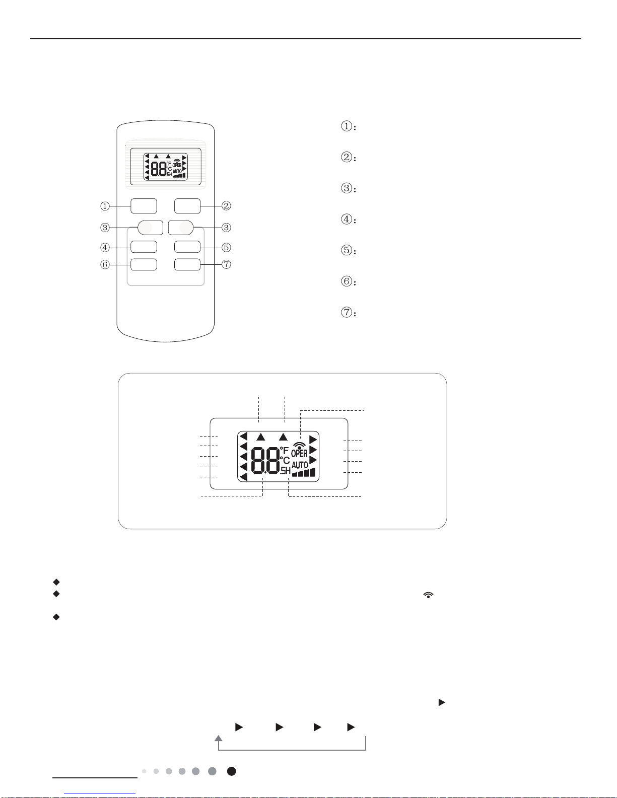
6.1 Remote Controller Introduction
AUTO
COOL
DRY
FAN
HEAT
T-ON T-OFF
SWING
SLEEP
LOCK
SPEED
+
_
ON/OFF
FAN SWING
SLEEP
TIMER
MODE
ON/OFF button
MODE button
+/- botton
FAN button
SWING button
SLEEP button
TIMER button
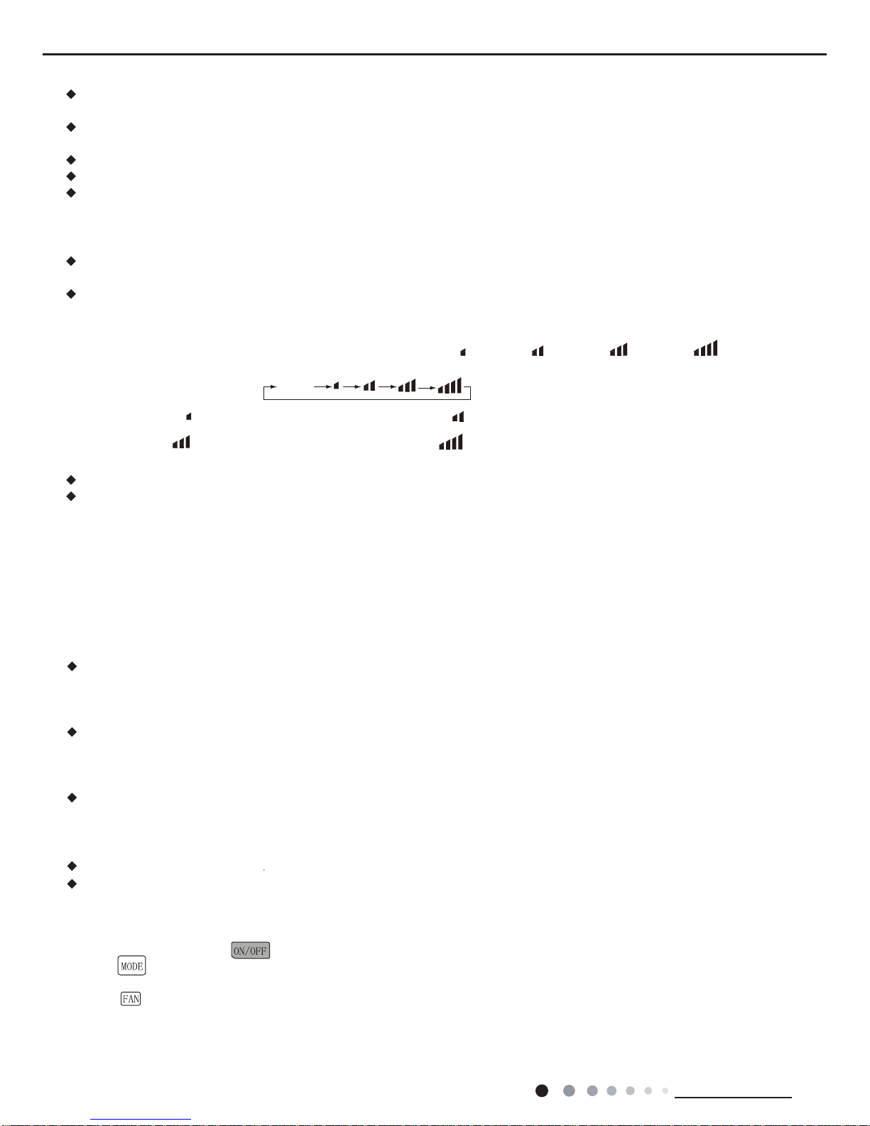
Icon Display on Remote Controller
Operation introduction of remote controller
For auto operation
Timer on Timer off
Sending signal
For air swing
For sleeping
For locking
For setting fan speed
Set temperature
Set time
For cooling
For drying
For fan only
For heating
AUTO
COOL
DRY
FAN
HEAT
T-ON T-OFF
SWING
SLEEP
LOCK
SPEED
Buttons on Remote Controller
Note:
When power is connected(stand by condition), you can operate the air conditioner through the remote controller.
When unit is on, each time you press the button on remote controller, the sending signal icon on the display of remote controller
will blink once. If the air conditioner gives out a beep sound, it means the signal has been sent.
When unit is off, set temperature will be displayed on the remote controller(If the light of indoor unit display is turned on, the
corresponding icon will be displayed); When unit is on, it will display the icon of the on-going function.
1. ON/OFF Button
Press this button to turn unit on/off.
2. MODE Button
Pressing this button once can select your required mode circularly as below(the corresponding icon
will be lit up after the mode is
selected):
AUTO COOL DRY FAN HEAT
14
Technical Information
Service Manual
When selecting auto mode, air conditioner will operate automatically according to ex-factory setting. Set temperature can't be
adjusted and won't be displayed either. Press FAN button to adjust fan speed. (This function is not available in this air conditioner.)
When selecting cool mode, air conditioner will operate under cool mode. Then press + or -- button to adjust set temperature. Press
FAN button to adjust fan speed.
When selecting dry mode, air conditioner will operate at low fan speed under dry mode. In dry mode, fan speed can't be adjusted.
When selecting fan mode, air conditioner will operate in fan mode only. Then press FAN button to adjust fan speed.
When selecting heat mode, air conditioner will operate under heat mode. Then press + or -- button to adjust set temperature. Press
FAN button to adjust fan speed.
3. +/- button
Pressing + or - button once will increase or decrease set temperature by 1 °F(°C). Hold + or -- button for 2s, set temperature on
remote controller will change quickly. Release the button after your required set temperature is reached.
When setting Timer On, Timer Off or Clock, press + or -- button to adjust the time (See TIMER Button for setting details).
4. FAN Button
Pressing this button can select fan speed circularly as: AUTO, SPEED 1(
), SPEED 2( ), SPEED 3( ), SPEED 4( ) (unavailable
in this air conditioner. Speed 4 is the same with speed 3).
Note:
Under Auto mode, air conditioner will select proper fan speed automatically according to ex-factory setting.
Fan speed can't be adjusted under Dry mode.
5. SWING Button
Press this button to turn on up&down air swing.
6. SLEEP Button
Under Cool, Heat, Dry mode, press this button to turn on Sleep function. Press this button to cancel Sleep function. Under Fan and
Auto mode, this function is unavailable.
Simple operationfi rst
1.After putting through power “
” button on remote controller to turn on the air conditioner.
2.Press “
” button to select your required operation mode: AUTO, COOL, DRY, FAN.
3.Press “+” or “-” button to set your required temperature.(temperature can’t adjusted under AUTO mode)
4.Press “
” button to select your required fan speed: auto, fi rst notch, second notch, third notch, fourth notch (fourthnotch is same
as third notch for this air conditioner.)
SPEED 2 (equals to medium fan speed)SPEED 1 (equals to low fan speed)
SPEED 3 (equals to high fan speed) SPEED 4
AUTO
7. TIMER Button
When unit is on, press this button to set Timer Off. T-OFF and H icon will be blinking. Within 5s, press + or - button to adjust the
When unit is off, press this button to set Timer On. T-ON and H icon will be blinking. Within 5s, press + or - button to adjust the
time for Timer On. Pressing + or - button once will increase or decrease the time by 0.5h. Hold + or - button for 2s, time will change
quickly. Release the button after your required set time is reached. Then press TIMER button to confirm it. T-ON and H icon will stop
blinking.
Cancel Timer On/Off: If Timer function is set up, press TIMER button once to review the remaining time. Within 5s, press TIMER
Note:
Range of time setting is: 0.5~24h
button again to cancel this function.
The interval between two motions can't exceed 5s, otherwise the remote controller will exit setting status.
time for Timer Off. Pressing + or - button once will increase or decrease the time by 0.5h. Hold + or - button for 2s, time will change
quickly. Release the button after your required set time is reached. Then press TIMER button to confirm it. T-OFF and H icon will
stop blinking.
15
Technical Information
Service Manual
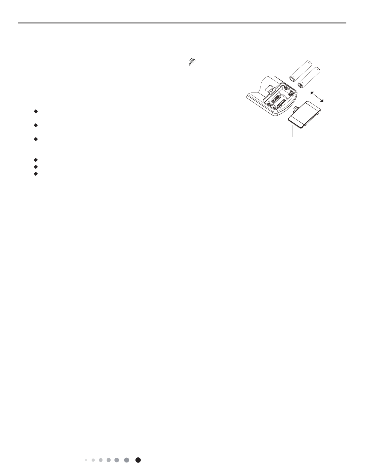
1. Press the back side of remote controller on the spot marked with , and then
push out the cover of battery box along the arrow direction.
2. Replace two No.7 (AAA 1.5V) dry batteries and make sure the positions of + and -polar are correct.
3. Reinstall the cover of battery box.
Note:
During operation, point the signal sender of the remote controller at the receiving
window of the indoor unit;
The distance between signal sender and receiving window should be within 8m.
There should be no obstacle between them.
Signal may be interfered easily in the room where there is fl uorescent lamp
or wireless telephone; Remote controller should be close to indoor unit during
operation.
Replace new batteries of the same model when replacement is required.
If you don't use remote controller for a long time, please take out the batteries.
If the display on remote controller is fuzzy or if there's no display, please replace
batteries.
battery
cover of battery box
remove
reinstall
Replacement of Batteries in Remote Controller

16
Technical Information
Service Manual
6.2 Brief Description of Modes and Functions
1. Temperature Parameters
◆
Indoor preset temperature (Tpreset)
◆
Indoor ambient temperature (Tamb.)
2. Basic Functions
Once energized, in no case should the compressor be restarted within less than 3 minutes. In the situation that memory function
is available, for the rst energization, if the compressor is at stop before de-energization, the compressor will be started without a
3-minute lag; if the compressor is in operation before de-energization, the compressor will be started with a 3-minute lag; and once
started, the compressor will not be stopped within 6 minutes regardless of changes in room temperature;
(1) Cooling Mode
①
Working conditions and process of cooling
Cooling conditions and process(09k)
a. When Tamb.≥Tpreset the unit starts cooling. In this case, the IDU fan motor, ODU fan motor and compressor run, and the IDU fan
motor runs at set speed;
b. When Tamb.=Tpreset-3℃, the compressor continuously operates below the frequency of 15Hz (not including 15Hz) for 15mins. If
Tamb.=Tset-3℃ still keeps the same, the compressor stops operation;
c. When Tamb.≤Tpreset-4℃, the compressor stops operation; ODU fan motor stops operation with a delay of 30s and IDU fan motor
operates at set speed;
d. When Tpreset-2℃<Tamb.<Tset, the unit will maintain its previous running status.
Cooling conditions and process(12k)
a.When Tamb.+Tindoor supplementary≥Tpreset, the unit starts cooling. In this case, the IDU fan motor, ODU fan motor and
compressor run, and the IDU fan motor runs at set speed;
b. When Tamb.+Tindoor supplementary≤Tpreset-2℃, the compressor stops operation; ODU fan motor stops operation with a delay
of 30s and IDU fan motor operates at set speed;
c.When Tpreset-2℃<Tindoor amb.+Tindoor supplementary<Tpreset, the unit will maintain its previous running status.
Under this mode, the four-way valve will be de-energized and temperature can be set within a range from 16 to 30oC.
If the compressor is shut down for some reason, the indoor fan and the swing device will operate at original state.
②
Protection
◆
Antifreeze protection
Under cooling and dehumidifying mode, 6 minutes after the compressor is started:
If T evap≤2oC, the compressor will operate at reduced frequency.
If T evap≤-1oCis detected for durative 3 minutes, the compressor will stop, and after 30 seconds, the outdoor fan will stop; and under
cooling mode, the indoor fan and the swing motor will remain at the original state.
If T evap. ≥10oCand the compressor has remained at OFF for at least 3 minutes, the compressor will resume its original operation
state.
◆
Total current up and frequency down protection
If I
total
≤6, frequency rise will be allowed; if I
total
≥7, frequency rise will not be allowed; if I
total
≥8, the compressor will run at reduced
frequency; and if I
total
≥9, the compressor will stop and the outdoor fan will stop with a time lag of 30s.
(2) Dehumidifying Mode
①
Working conditions and process of dehumidifying
If Tamb>Tpreset, the unit will enter cooling and dehumidifying mode, in which case the compressor and the outdoor fan will operate
and the indoor fan will run at low speed.
If Tpreset -2oC≤Tamb≤Tpreset, the compressor remains at its original operation state.
If Tamb.< Tpreset -2oC, the compressor will stop, the outdoor fan will stop with a time lag of 30s, and the indoor fan will operate at
low speed.
②
Protection
Protection is the same as that under the cooling mode.
(3) Heating Mode

17
Technical Information
Service Manual
①
Working conditions and process of heating
If Tamb.≤Tpreset +2oC, the unit enters heating mode, in which case the four-way valve, the compressor and the outdoor fan will
operate simultaneously, and the indoor fan will run at preset speed in the condition of preset cold air prevention.
If T amb.≥Tpreset +5oC, the compressor will stop, the outdoor fan will stop with a time lag of 30s, and the indoor fan will stop after
60-second blow at low speed
If Tpreset +2oC<T amb.< Tpreset +5oC, the unit will maintain its original operating status.
Under this mode, the four-way valve is energized and temperature can be set within a range of 16 - 30oC. The operating symbol, the
heating symbol and preset temperature are revealed on the display.
②
Condition and process of defrost
When duration of successive heating operation is more than 45 minutes, or accumulated heating time more than 90 minutes, and
one of the following conditions is reached, the unit will enter the defrost mode after 3 minutes.
(1)T outdoor ambient>5oC, T outdoor tube≤-2oC;
(2) -2oC≤T outdoor ambient<5oC, T outdoor tube≤-6oC;
(3) -5oC≤T outdoor ambient<-2oC, T outdoor tube≤-8oC;
(4)-10oC≤Toutdoor ambient<-5oC, Toutdoortube-T compensatory≤(T outdoor ambient-3oC)
(5)T outdoor ambient<-10oC, T outdoortube-T compensatory≤(T outdoor ambient-3oC)
(after energizing, T compensatory=0oC during the rst defrosting; if it is not the rst defrosting, T compensatory is conrmed by T
outdoortube of quitting last defrosting:
a. whenT outdoor tube>2oC, T compensatory=0oC; b. whenT outdoor tube≤2oC, T compensatory=3oC)
At that time, the indoor fan stops and the compressor stops, and after 30 seconds the outer fan will stop, and then after 30 seconds,
the four-way valve will stop. After 30 seconds, the compressor is initiated for raising the frequency to defrost frequency.
When the compressor has operated under defrost mode for 7.5 minutes, or T outdoor ambient≥10oC, the compressor will be
converted to 46Hz operation. After 30 seconds, the compressor will stop. And after another 30 seconds, the four-way valve will
be opened, and after 60 seconds, the compressor and the outer fan will be started, the indoor fan will run under preset cold air
prevention conditions, and H1 will be displayed at temperature display area on the display panel. Defrost frequency is 85Hz.
③
Protection
◆
Cold air prevention
The unit is started under heating mode (the compressor is ON):
①
In the case of T indoor amb. <24oC: if T tube≤40oC and the indoor fan is at stop state, the indoor fan will begin to run at low speed
with a time lag of 2 minutes. Within 2 minutes, if T tube>40oC, the indoor fan also will run at low speed; and after 1-minute operation
at low speed, the indoor fan will be converted to operation at preset speed. Within 1-minute low speed operation or 2-minute non-
operation, if T tube>42oC, the fan will run at present speed.
②
In the case of T indoor amb. ≥24oC: if T tube≤42oC, the indoor fan will run at low speed, and after one minute, the indoor fan will be
converted to preset speed. Within one-minute low speed operation, if T tube>42oC, the indoor fan will be converted to preset speed.
Note: T indoor amb. indicated in
①
and
②
refers to, under initially heating mode, the indoor ambient temperature before the
command to start the compressor is performed according to the program, or after the unit is withdrawn from defrost, the indoor
ambient temperature before the defrost symbol is cleared.
◆
Total current up and frequency down protection
If the total current I
total
≤6, frequency rise will be allowed; if I
total
≥7, frequency rise will not be allowed; if I
total
≥8, the compressor will run
at reduced frequency; and if I
total
≥9, the compressor will stop and the outdoor fan will stop with a time lag of 30s.
(4) Fan Mode
Under the mode, the indoor fan will run at preset speed and the compressor, the outdoor fan, the four-way valve and the electric
heater will stop.
Under the mode, temperature can be set within a range of 16 - 30oC .
(5) AUTO Mode
①
Working conditions and process of AUTO mode
a. When T ambient ≥26oC, the unit will operate in Cool mode. The set temperature is 25oC.
b. When T ambient ≤22oC, the heat pump unit will operate in Heat mode., set temperature be 20oC; the cooling only unit will operate
in Fan mode, set temperature be 25oC.
c. When 23oC≤T ambient ≤25oC, the unit will operate in the previous state. If it is energized for the rst time, it will operate in Fan
mode.
d. Under auto mode, if its cooling mode, operation frequency is same as that under cooling mode; if its heating mode, operation
frequency is same as that under heating mode.
18
Technical Information
Service Manual
②
Protection
a. In cooling operation, protection is the same as that under the cooling mode;
b. In heating operation, protection is the same as that under the heating mode;
c. When ambient temperature changes, operation mode will be converted preferentially. Once started, the compressor will
remain unchanged for at least 6 minutes.
(6) Common Protection Functions and Fault Display under COOL, HEAT, DRY and AUTO Modes
①
Overload protection
T tube: measured temperature of outdoor heat exchanger under cooling mode; and measured temperature of indoor heat exchanger
under heating mode.
1) Cooling overload
a.If T tube≤52oC, the unit will return to its original operation state.
b.If T tube≥55oC, frequency rise is not allowed.
c.If T tube≥58oC, the compressor will run at reduced frequency.
d.If T tube≥62oC, the compressor will stop and the indoor fan will run at preset speed.
2) Heating overload
a.If T tube≤50oC, the unit will return to its original operation state.
b.If T tube≥53oC, frequency rise is not allowed.
c.If T tube≥56oC, the compressor will run at reduced frequency.
d.If T tube≥60oC, the compressor will stop and the indoor fan will blow residue heat and then stop.
②
Exhaust temperature protection of compressor
a.If exhaust temperature ≥98oC, frequency is not allowed to rise.
b.If exhaust temperature ≥103oC, the compressor will run at reduced frequency.
c.If exhaust temperature ≥110oC, the compressor will stop.
d.If exhaust temperature ≤90oCand the compressor has stayed at stop for at least 3 minutes, the compressor will resume its operation.
③
Communication fault
If the unit fails to receive correct signals for durative 3 minutes, communication fault can be justied and the whole system will stop.
④
Module protection
Under module protection mode, the compressor will stop. When the compressor remains at stop for at least 3 minutes, the compressor will
resume its operation. If module protection occurs six times in succession, the compressor will not be started again.
⑤
Overload protection
If temperature sensed by the overload sensor is over 115oC, the compressor will stop and the outdoor fan will stop with a time lag of 30
seconds. If temperature is below 95oC, the overload protection will be relievedoC.
⑥
DC bus voltage protection
If voltage on the DC bus is below 150V or over 420V, the compressor will stop and the outdoor fan will stop with a time lag of 30 seconds.
When voltage on the DC bus returns to its normal value and the compressor has stayed at stop for at least 3 minutes, the compressor will
resume its operation.
⑦
Faults of temperature sensors
Designation of sensors Faults
Indoor ambient temperature
The sensor is detected to be open-circuited or short-circuited for successive 30
seconds
Indoor tube temperature
The sensor is detected to be open-circuited or short-circuited for successive 30
seconds
Outdoor ambient temperature
The sensor is detected to be open-circuited or short-circuited for successive 30
seconds
Outdoor tube temperature
The sensor is detected to be open-circuited or short-circuited for successive 30
seconds, and no detection is performed within 10 minutes after defrost begins.
Exhaust
After the compressor has operated for 3 minutes, the sensor is detected to be
open-circuited or short-circuited for successive 30 seconds.
Overload
After the compressor has operated for 3 minutes, the sensor is detected to be
open-circuited or short-circuited for successive 30 seconds.
Zero-crossing inspection circuit
malfunction of the IDU fan motor
Zero-crossing signal is not detected for continuously 3s; Or the interval between
the zero-crossing signals in 3s>25ms (power frequency: 50Hz)
19
Technical Information
Service Manual
Indoor Units
(1) ON/OFF
Press the remote button ON/OFF: the on-off state will be changed once each time you press the button.
(2) Mode Selection
Press the remote button MODE, then select and show in the following ways: AUTO, COOL, DRY, FAN, HEAT, AUTO.
(3) Temperature Setting Option Button
Each time you press the remote button TEMP+ or TEMP-, the setting temperature will be up or down by 1oC. Regulating
Range: 16~30oC, the button is useless under the AUTO mode.
(4) Time Switch
You should start and stop the machine according to the setting time by remote control.
(5) SLEEP State Control
a. When the air conditioner is under the mode of COOL, DRY, and the SLEEP mode has been set well, after the SLEEP state keeps about
1 hour, the pre-setting T will raise 1oC, and it will raise 1oC again after 2 hours, so it raise 2oC in 2 hours, then it will run on at the setting
temperature and wind speed.
b. When the air conditioner is under the mode of HEAT, and the Timer has been set well, after the SLEEP state keeps about 1 hour, the pre-
setting T will reduce 1oC, and it will reduce 1oC again after 2 hours, so it reduce 2oC in 2 hours, then it will run on at the setting temperature
and wind speed.
c. The setting temperature keeps the same under the FAN mode and AUTO mode.
(6) Buzzer Control
a. Cooling only model:The buzzer will send a “Di Di” sound when the air conditioner is powered up or received the information sent by the
remote control or there is a button input, the single tube cooler doesnt receive the remote control ON signal under the mode of heating
mode.
b. Cooling and heating model:The buzzer will send a “Di” sound when the air conditioner is powered up or received the information sent by
the remote control or there is a button input, the single tube cooler doesnt receive the remote control ON signal under the mode of heating
mode.
(7) Auto button
If the controller is on, it will stop by pressing the button, and if the controller is off, it will be automatic running state by pressing the button,
swing on and light on, and the main unit will run based on the remote control if there is remote control order.
(8) Up-and-Down Swinging Control
When power on, the up-and-down motor will firstly move the air deflector to counter-clockwise, close the air outlet. After starting the
machine, if you dont set the swinging function, heating mode and auto-heating mode, the up-and-down air deflector will move to D
clockwise; under other modes, the up-and-down air deector will move to L1. If you set the swinging function when you start the
machine, then the wind blade will swing between L and D. The air deector has 7 swinging states: Location L, Location A, Location B,
Location C, Location D, Location L to Location D, stop at any location between L-D (the included angle between L~D is the same). The
air deector will be closed at 0 Location, and the swinging is effectual only on condition that setting the swinging order and the inner fan is
running. The indoor fan and compressor may get the power when air deector is on the default location.
(9) Display
①
Operation pattern and mode pattern display
All the display patterns will display for a time when the power on, the operation indication pattern will display in red under standby status.
When the machine is start by remote control, the indication pattern will light and display the current operation mode (the mode light includes:
L1
A1
B1
C1
D1
L
A
B
C
D
Heating angle
Cooling angle
O(0°)
O(0°)

20
Technical Information
Service Manual
Cooling, heating and dehumidify). If you close the light key, all the display patterns will close.
②
Double-8 display
According to the different setting of remote control, the nixie light may display the current temperature (the temperature scope is
from 16oC to 30oC) and indoor ambient temperature. The set temperature displayed in auto cooling and fan mode is 25
℃ ,
The set
temperature displayed in auto heating mode is 20℃and the temperature will display H1 under the defrosting mode.(If you set the
fahrenheit temperature display, the nixie light will display according to fahrenheit temperature)
(10) Protection function and failure display
E2: Freeze-proong protection E4: Exhausting protection E5: Overcurrent protection
E6: Communication failure H4: Overload protection
F1: Indoor ambient sensor start and short circuit (continuously measured failure in 30S)
F2: Indoor evaporator sensor start and short circuit (continuously measured failure in 30S)
F3: Outdoor ambient sensor start and short circuit (continuously measured failure in 30S)
F4: Outdoor condenser sensor start and short circuit (continuously measured failure in 30S, and dont measure within 10 minutes
after defrosted)
F5: Outdoor exhausting sensor start and short circuit (continuously measured failure in 30S after the compressor operated 3 minutes)
H3: Overload protection of compressor H5: Module protection
PH: High-voltage protection PL: Low-voltage protection
P1: Nominal cooling and heating P2: Maximum cooling and heating
P3: Medium cooling and heating P0: Minimum cooling and heating
(11) Drying Function
You may start or stop the drying function under the modes of cooling and dehumidify at the starting status (The modes of automatism,
heating and air supply do not have drying function). When you start the drying function, after stop the machine by pressing the switch
button, you should keep running the inner fans for 10 minutes under low air damper (The swing will operate as the former status
within 10 minutes, and other load is stopped), then stop the entire machine; When you stop the drying function, press the switch
button will stop the machine directly. When you start the drying function, operating the drying button will stop the inner fans and close
the guide louver.
(12) Memory function when interrupting the power supply
Memory content: mode, swing function, light, set temperature and wind speed. After interrupted the power supply, the machine will
start when recovering the power according to the memory content automatically. If the last remote control command has not set
the timed function, the system will remember the last remote control command and operate according it. If the last remote control
command has set timed function and the power supply is interrupted before the timed time, the system will remember the timed
function of the last remote control command, the timed time will recounted form power on. If the last remote control command has
set timed function, the time is out and the system is start or stop according to the set time when the power supply is interrupted, the
system will remember the operation status before the power supply was interrupted, and do not carry out timed action; The timed
clock will not remembered.
(13) Sleep function
In this mode, the system will select proper sleep curve to operate according to different set temperature.
①
If start up sleep function under cooling or drying mode, the system will increase set temperature automatically within a certain
range to operate.
②
If start up sleep function under heating mode, the system will decrease set temperature automatically within a certain range to
operate.
21
Installation and Maintenance
Service Manual
Part
Ⅱ
: Installation and Maintenance
1. Select the installation location according to the requirement of this manual.(See the requirements in installation
part)
2. Handle unit transportation with care; the unit should not
be carried by only one person if it is more than 20kg.
3. When installing the indoor unit and outdoor unit, a sufcient xing bolt must be installed; make sure the installation
support is rm.
4. Ware safety belt if the height of working is above 2m.
5. Use equipped components or appointed components during installation.
6. Make sure no foreign objects are left in the unit after nishing installation.
Electrical Safety Precautions:
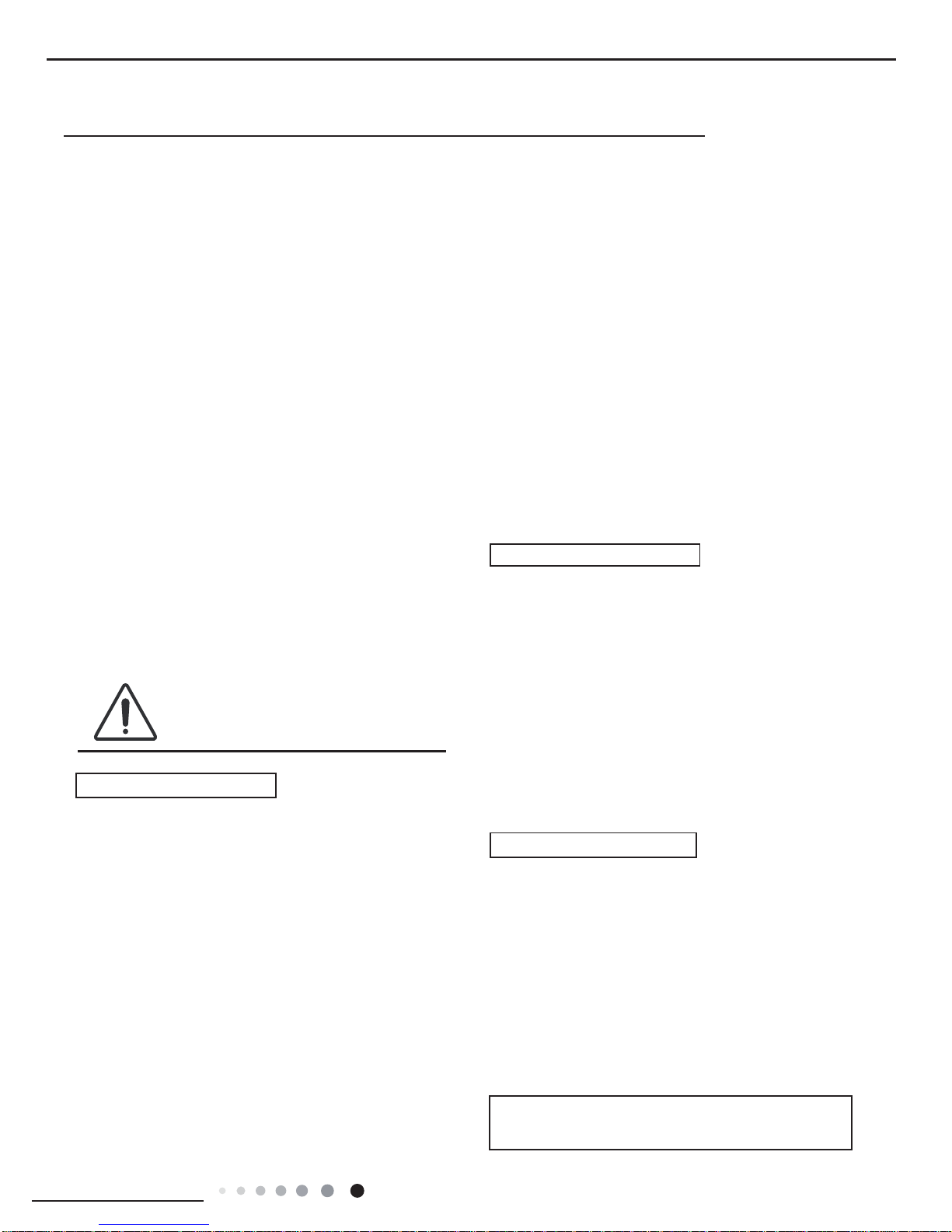
7. Notes for Installation and Maintenance
Safety Precautions:
Important!
Please read the safety precautions carefully before
installation and maintenance.
The following contents are very important for installation
and maintenance.
Please follow the instructions below.
●The installation or maintenance must accord with the
instructions.
●Comply with all national electrical codes and local
electrical codes.
●Pay attention to the warnings and cautions in this
manual.
●All installation and maintenance shall be performed by
distributor or qualied person.
●All electric work must be performed by a licensed
technician according to local regulations and the
instructions given in this manual.
●Be caution during installation and maintenance. Prohibit
incorrect operation to prevent electric shock, casualty and
other accidents.
1. Cut off the power supply of air conditioner before
checking and maintenance.
2. The air condition must apply specialized circuit and
prohibit share the same circuit with other appliances.
3. The air conditioner should be installed in suitable
location and ensure the power plug is touchable.
4. Make sure each wiring terminal is connected firmly
during installation and maintenance.
5. Have the unit adequately grounded. The grounding
wire can’t be used for other purposes.
6. Must apply protective accessories such as protective
boards, cable-cross loop and wire clip.
7. Th e live wire, neutral wire and g rounding wire of
power supply must be corresponding to the live wire,
neutral wire and grounding wire of the air conditioner.
8. The power cord and power connection wires can’t be
pressed by hard objects.
9. If power cord or connection wire is broken, it must be
replaced by a qualied person.
1. Avoid contact between refrigerant and re as it generates
poisonous gas; Prohibit prolong the connection pipe by
welding.
2. Apply specied refrigerant only. Never have it mixed with
any other refrigerant. Never have air remain in the refrigerant
line as it may lead to rupture or other hazards.
3. Make sure no refrigeran t g a s i s le a k i n g ou t wh e n
installation is completed.
4. If there is refri ger ant le akage , p lea se take suf fic ient
measure to minimize the density of refrigerant.
5. Never touch the refrigerant piping or compressor without
wearing glove to avoid scald or frostbite.
Warnings
Refrigerant Safety Precautions:
Improper installation may lead to re hazard, explosion,
electric shock or injury.
Installation Safety Precautions:
10. If the power cord or connection wire is not long enough,
please get the specialized power cord or connection wire
from the manufacture or distributor. Prohibit prolong the wire
by yourself.
11. For the air conditioner without plug, an air switch must
be installed in the circuit. The air switch should be all-pole
parting and the contact parting distance should be more than
3mm.
12. Make sure all wires and pipes are connected properly and
the valves are opened before energizing.
13. Check if there is electric leakage on the unit body. If yes,
please eliminate the electric leakage.
14. Replace the fuse with a new one of the same specication
if it is b urnt down; don’t re place it with a cooper wire or
conducting wire.
15. If the unit is to be installed in a humid place, the circuit
breaker must be installed.
22
Installation and Maintenance
Service Manual
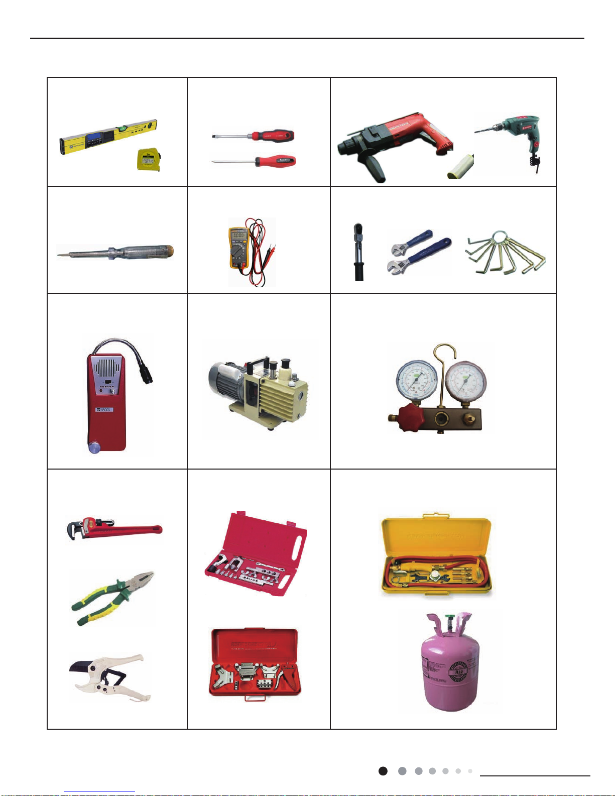
Main Tools for Installation and Maintenance
1. Level meter, measuring tape
4. Electroprobe
7. Electronic leakage detector
10. Pipe pliers, pipe cutter
2. Screw driver
5. Universal meter
8. Vacuum pump
11. Pipe expander, pipe bender
3. Impact drill, drill head, electric drill
6. To rque wrenc h , o p en-e n d wre n ch, inne r
hexagon spanner
9. Pressure meter
12. Soldering appliance, refrigerant container
23
Installation and Maintenance
Service Manual
8. Installation
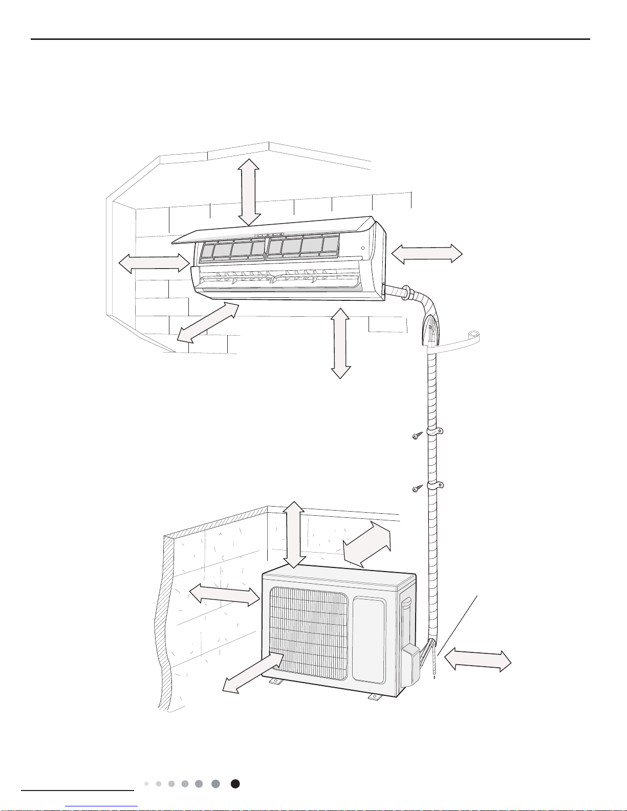
8.1 Installation Dimension Diagram
Drainage pipe
At least 250cm
At least 15cm
At least 50cm
At least 50cm
At least
30cm
At least 300cm
At least 200cm
Space to the oor
Space to the obstruction
Space to the
obstruction
Space to the
obstruction
Space to the ceiling
Space to the obstruction
Space to the obstruction
At least 30cm
At least 15cm
At least 15cm
Space to the wall
Space to the wall
Space to the wall
24
Installation and Maintenance
Service Manual
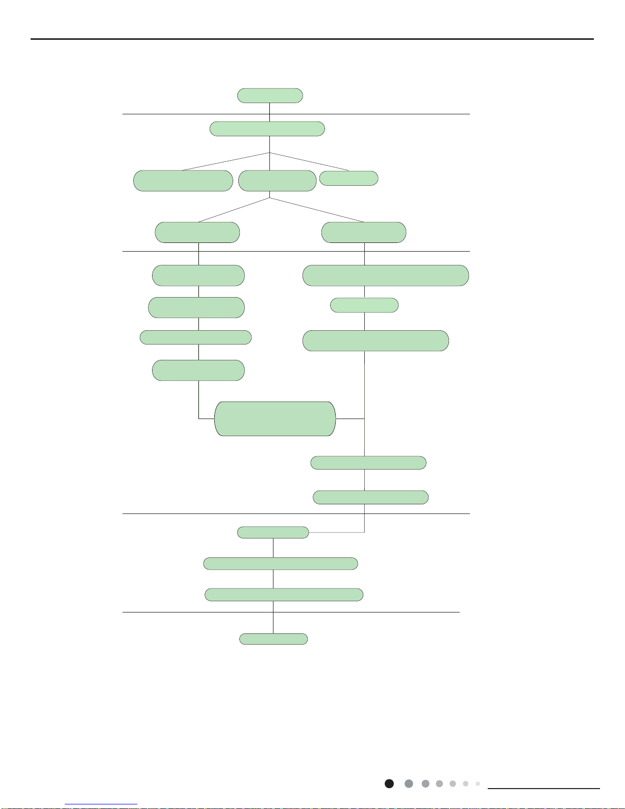
Installation procedures
Preparation before installation
Prepare tools
Read the requirements
for electric connection
select installation
location
Select indoor unit
installation location
Install wall-mounting
frame, drill wall holes
Connect pipes of indoor
unit and drainage pipe
Connect wires of indoor unit
Connect wires of outdoor unit
Bind up pipes and
hang the indoor unit
Make the bound pipes pass
through the wall hole and then
connect outdoor unit
Neaten the pipes
Vacuum pumping and leakage detection
Check after installation and test operation
Finish installation
Note: this flow is only for reference; please find the more detailed installation steps in this section.
Select outdoor unit
installation location
Install the support of outdoor unit
(select it according to the actual situation)
Install drainage joint of outdoor unit
(only for cooling and heating unit)
Connect pipes of outdoor unit
Start installation
Fix outdoor unit
 Loading...