

Gree GWH(12)KF-K3DNA6E/I, GWH(12)KF-K3DNB1E/I, GWH(07)KF-K3DNA6E/I, GWH(09)KF-K3DNB1E/I, GWH(07)KF-K3DNA8E/I Service Manual
...
GREE ELECTRIC APPLIANCES,INC.OF ZHUHAI
Change for Life
Service Manual
Models:
GWH(07)KF-K3DNA8E/I
GWH(07)KF-K3DNA6E/I
GWH(07)KF-K3DNB4E/I
GWH(07)KF-K3DNB1E/I
GWH(07)KF-K3DNA5E/I
GWH(07)KF-K3DNB2E/I
GWH(09)KF-K3DNA6E/I
GWH(09)KF-K3DNB1E/I
GWH(09)KF-K3DNA5E/I
GWH(09)KF-K3DNB2E/I
GWH(12)KF-K3DNA6E/I
GWH(12)KF-K3DNB4E/I
GWH(12)KF-K3DNB1E/I
GWH(12)KF-K3DNB2E/I
GWH(12)KF-K3DNA5E/I
GWH(18)KG-K3DNA6E/I
GWH(18)KG-K3DNB2E/I
GWH(18)KG-K3DNA8E/I
GWH(18)KG-K3DNB1E/I
GWH(18)KG-K3DNA5E/I
(Refrigerant R410A)

Service Manual
Table of Contents
Table of Contents
Part
Ⅰ
: Technical Information
................................................................................. 1
1. Summary
................................................................................................................................ 1
2. Specications
.................................................................................................................... 2
2.1 Specication Sheet
..............................................................................................................2
2.2 Noise Criteria Curve Tables for Both Models
................................................................. 4
3. Outline Dimension Diagram
.................................................................................. 5
4. Electrical Part
..................................................................................................................... 6
4.1 Wiring Diagram ...........................................................................................................................6
4.2 PCB Printed Diagram ................................................................................................................. 8
5. Function and Control
................................................................................................ 10
5.1 Remote Controller Introduction ...............................................................................................10
5.2 Brief Description of Modes and Functions ................................................................................14
Part
Ⅱ
: Installation and Maintenance
........................................................... 18
6. Notes for Installation and Maintenance
.................................................... 18
7. Installation
.......................................................................................................................... 20
7.1 Installation Dimension Diagram ................................................................................................ 20
7.2 Installation Parts-Checking ....................................................................................................... 22
7.3 Selection of Installation Location .............................................................................................. 22
7.4 Requirements Forelectric Connection ...................................................................................... 22
7.5 Installation of Indoor Unit .......................................................................................................... 22
7.6 Check after Installation and Test Operation ............................................................................. 25
8. Maintenance
...................................................................................................................... 26
8.1 Error Code ................................................................................................................................ 26
8.2 Troubleshooting ...................................................................................................................... 28
8.3 Maintenance Method for Normal Malfunction ........................................................................... 34
9. Exploded View and Parts List
........................................................................... 36
10. Removal Procedure
................................................................................................. 46

Service Manual
Table of Contents
Appendix:
................................................................................................................................... 52
Appendix 1: Reference Sheet of Celsius and Fahrenheit
...................................................... 52
Appendix 2: Conguration of Connection Pipe
........................................................................52
Appendix 3: Pipe Expanding Method
.........................................................................................53
Appendix 4: List of Resistance for Temperature Sensor
........................................................ 54
1
Technical Information
Service Manual
1. Summary
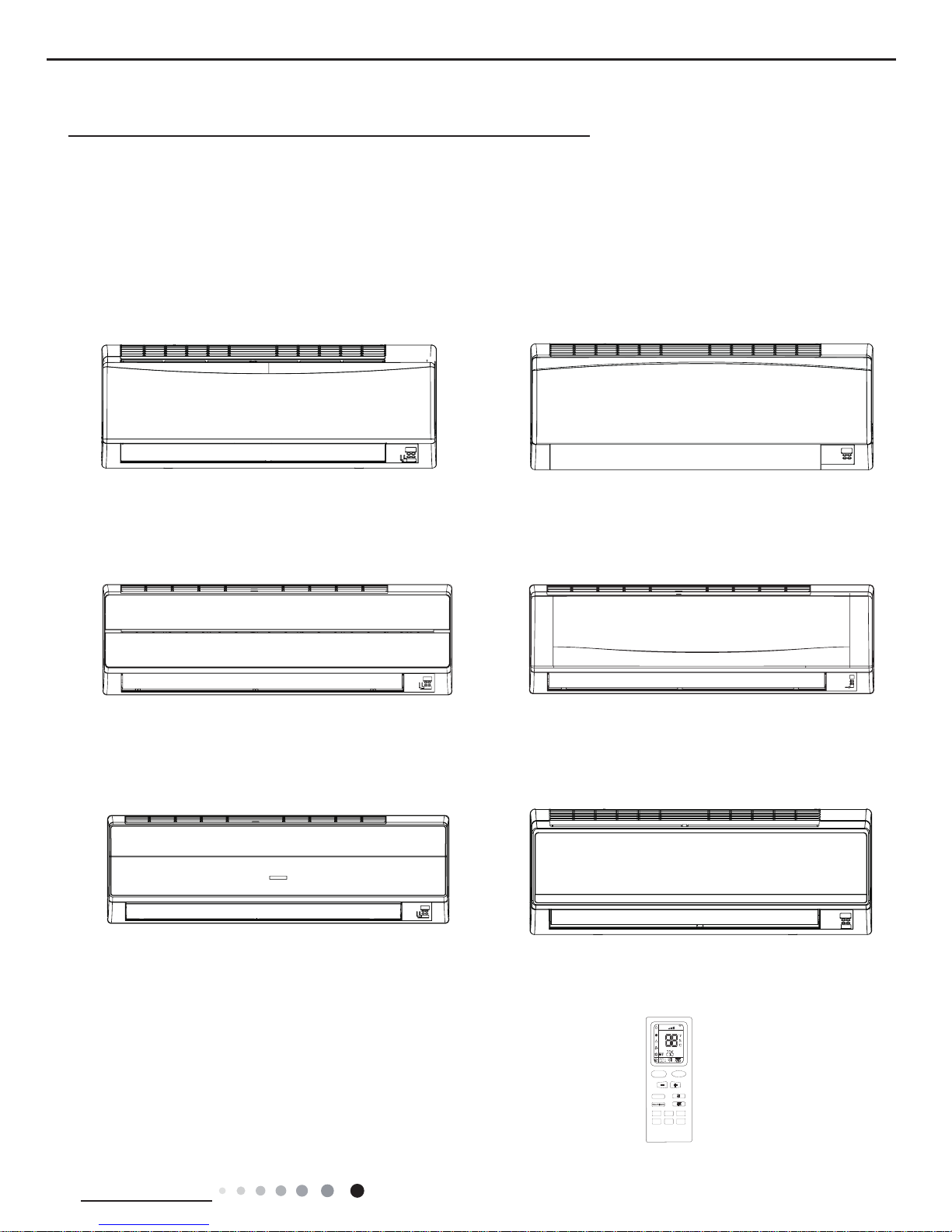
Indoor Unit:
GWH(07)KF-K3DNA6E/I
GWH(09)KF-K3DNA6E/I
GWH(12)KF-K3DNA6E/I
GWH(18)KG-K3DNA6E/I
GWH(07)KF-K3DNA8E/I
GWH(18)KG-K3DNA8E/I
GWH(07)KF-K3DNB4E/I
GWH(12)KF-K3DNB4E/I
GWH(07)KF-K3DNB2E/I
GWH(09)KF-K3DNB2E/I
GWH(12)KF-K3DNB2E/I
GWH(18)KG-K3DNB2E/I
GWH(12)KF-K3DNA5E/I
GWH(18)KG-K3DNA5E/I
GWH(07)KF-K3DNA5E/I
GWH(09)KF-K3DNA5E/I
Part
Ⅰ
: Technical Information
GWH(07)KF-K3DNB1E/I
GWH(09)KF-K3DNB1E/I
GWH(12)KF-K3DNB1E/I
GWH(18)KG-K3DNB1E/I
Remote Controller:
FAN
AUTO
OPER
HEALTH
AIR
FILTER
TURBO
ON/OFF
X-FAN
HOUR
HUMIDITY
ON/OFF
MODE
FAN
X-FAN
TURBO
TEMP
TIMER
SLEEP
LIGHT
YB1F2(XFAN)
2
Technical Information
Service Manual
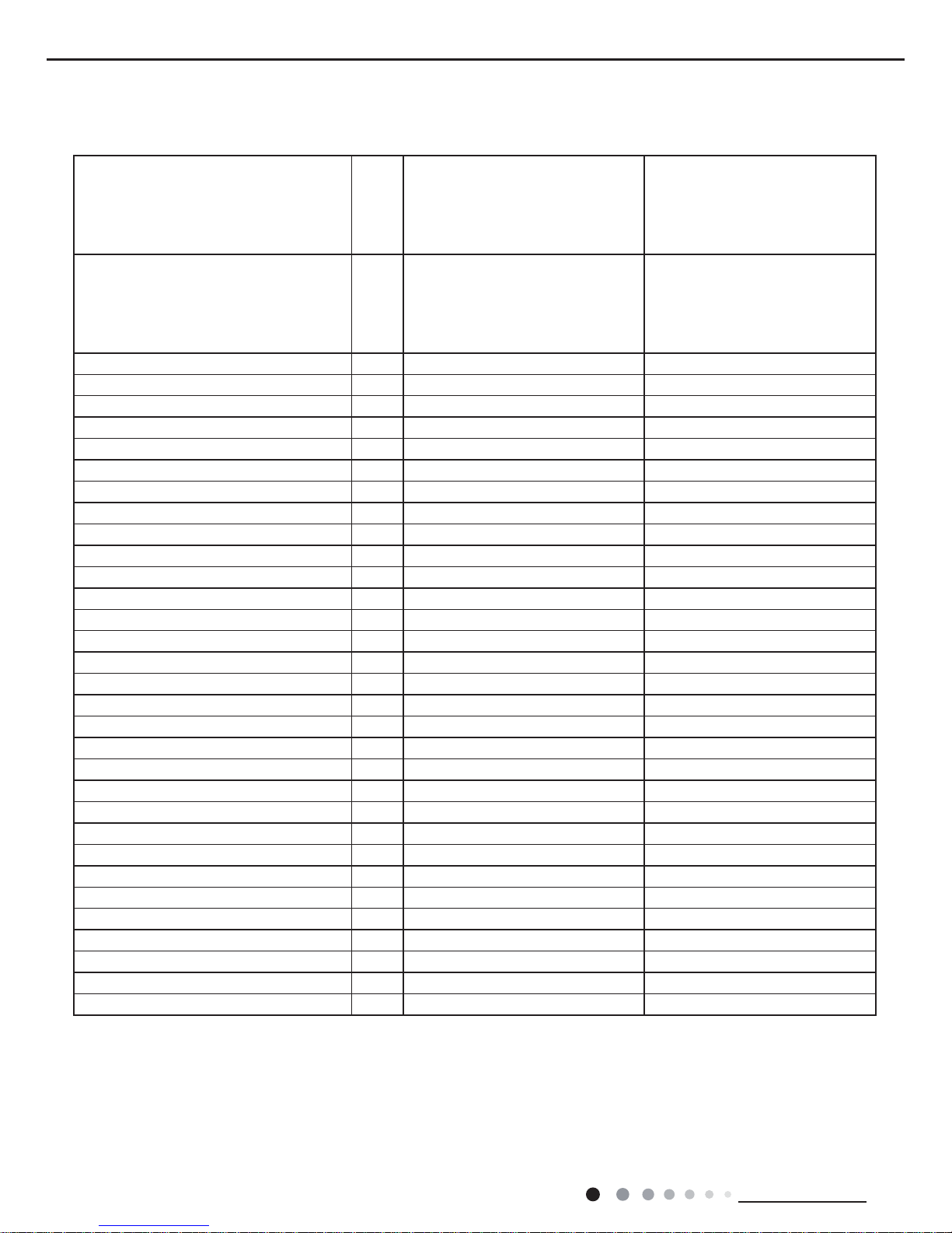
2. Specications
2.1 Specication Sheet
The above data is subject to change without notice. Please refer to the nameplate of the unit.
Model
GWH(07)KF-K3DNA6E/I
GWH(07)KF-K3DNA8E/I
GWH(07)KF-K3DNB4E/I
GWH(07)KF-K3DNB1E/I
GWH(07)KF-K3DNA5E/I
GWH(07)KF-K3DNB2E/I
GWH(09)KF-K3DNA6E/I
GWH(09)KF-K3DNB1E/I
GWH(09)KF-K3DNA5E/I
GWH(09)KF-K3DNA6E/I
GWH(09)KF-K3DNB2E/I
Product Code
CB146N26201
CB146N32800
CB146N33300
CB146N30000
CB146N35500
CB409N01400
CB146N26301
CB146N30100
CB146N28301
CB146N26302
CB409N01100
Rated Voltage V~ 220-240 220-240
Rated Frequency Hz 50 50
Phases 1 1
Cooling Capacity KW 2.1 2.6
Heating Capacity KW 2.6 2.8
Air Flow Volume (SH/H/M/L) m3/h 550/520/370/280 600/520/370/280
Dehumidifying Volume L/h 0.6 0.8
Fan Type Cross-ow Cross-ow
Fan Diameter-height mm Φ92X594 Φ92X594
Fan Motor Speed (SH/H/M/L) Cool rpm 1350/1100/900/700 1350/1100/900/700
Fan Motor Speed (SH/H/M/L) Heat rpm 1350/1140/980/820 1350/1140/980/820
Fan Motor Power Output W 10 10
Fan motor running current A 0.16 0.16
Fan Motor Capacitor μF 1.2 1.2
Evaporator Material Aluminum Fin-copper Tube Aluminum Fin-copper Tube
Evaporator Pipe Diameter mm 7 7
Evaporator Number of Rows 2 2
Evaporator Fin Pitch mm 1.4 1.4
Evaporator Length(L) X Height(H) X Width(W) mm 610X25.4X294 610X25.4X294
Motor Model FN10V-PG FN10V-PG
Overload Protector 3.15 3.15
Motor Full Load Amp(FLA) A 0.16 0.16
Sound Pressure Level (SH/H/M/L) dB (A) 40/38/30/24 41/38/30/24
Sound Power Level (SH/H/M/L) dB (A) 50/48/40/34 51/48/40/34
Outline Dimension (WXHXD) mm 770X283X201 770X283X201
Package Carton Dimension (LXWXH) mm 844X342X261 844X342X261
Package Dimension (LXWXH) mm 847X345X276 847X345X276
Net Weight kg 8 8
Gross Weight kg 10 10
Liquid Pipe mm Φ6 Φ6
Gas Pipe(to Indoor Unit) mm Φ9.52 Φ9.52
3
Technical Information
Service Manual
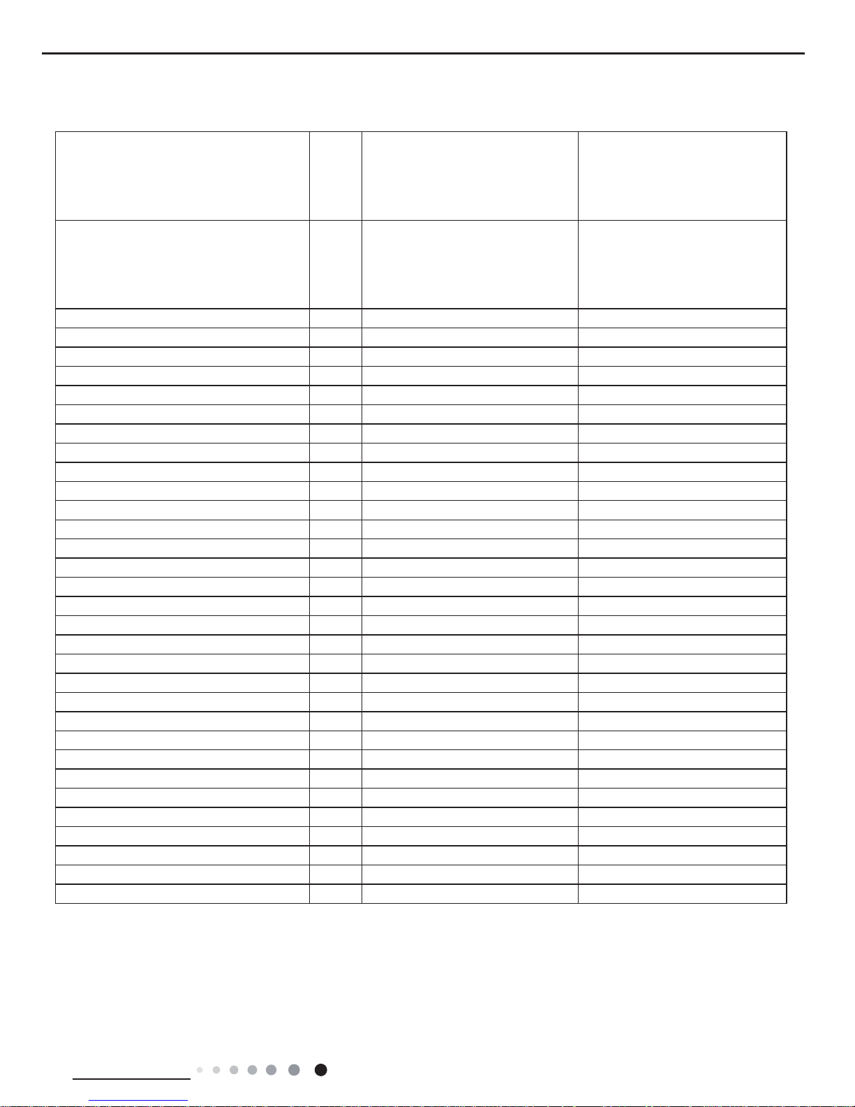
The above data is subject to change without notice. Please refer to the nameplate of the unit.
Model
GWH(12)KF-K3DNA6E/I
GWH(12)KF-K3DNB4E/I
GWH(12)KF-K3DNB1E/I
GWH(12)KF-K3DNA5E/I
GWH(12)KF-K3DNA6E/I
GWH(12)KF-K3DNB2E/I
GWH(18)KG-K3DNA6E/I
GWH(18)KG-K3DNB2E/I
GWH(18)KG-K3DNB1E/I
GWH(18)KG-K3DNA5E/I
Product Code
CB146N26401
CB146N33400
CB146N30500
CB146N33001
CB146N26402
CB409N00900
(CB146N32500/CB146N26501)
CB409N01900
CB146N35400
CB146N32901
Rated Voltage V~ 220-240 220-240
Rated Frequency Hz 50 50
Phases 1 1
Cooling Capacity KW 3.5 5.3
Heating Capacity KW 3.8 5.8
Air Flow Volume (SH/H/M/L) m3/h 680/560/410/300 800/680/560/460
Dehumidifying Volume L/h 1.4 1.8
Fan Type Cross-ow Cross-ow
Fan Diameter-height mm Φ92X594 Φ98X710
Fan Motor Speed (SH/H/M/L) Cool rpm 1350/1150/950/750 1350/1100/950/800
Fan Motor Speed (SH/H/M/L) Heat rpm 1350/1190/1020/850 1400/1200/1050/900
Fan Motor Power Output W 10 20
Fan motor running current A 0.16 0.31
Fan Motor Capacitor μF 1.2 1.5
Evaporator Material Aluminum Fin-copper Tube Aluminum Fin-copper Tube
Evaporator Pipe Diameter mm 7 7
Evaporator Number of Rows 2 2
Evaporator Fin Pitch mm 1.4 1.4
Evaporator Length(L) X Height(H) X Width(W) mm 610X25.4X294 657X25.4X304.8
Motor Model FN10V-PG FN20V-PG
Overload Protector 3.15 3.15
Motor Full Load Amp(FLA) A 0.16 0.31
Sound Pressure Level (SH/H/M/L) dB (A) 42/39/31/25 45/40/37/32
Sound Power Level (SH/H/M/L) dB (A) 52/49/41/35 55/50/47/42
Outline Dimension (WXHXD) mm 770X283X201 865X305X215
Package Carton Dimension (LXWXH) mm 844X342X261 945X380X295
Package Dimension (LXWXH) mm 847X345X276 948X383X310
Net Weight kg 9 12
Gross Weight kg 11 15
Liquid Pipe mm Φ6 Φ6
Gas Pipe(to Indoor Unit) mm Φ9.52 Φ12
4
Technical Information
Service Manual
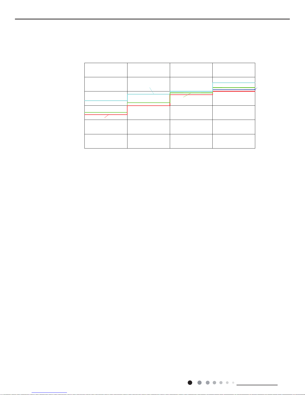
2.2 Noise Criteria Curve Tables for Both Models
0
10
Noice/dB(A)
20
30
40
50
60
Low Middle High Super High
Indoor Fan Motor Rotating Speed
7K
9K
12K
18K
5
Technical Information
Service Manual
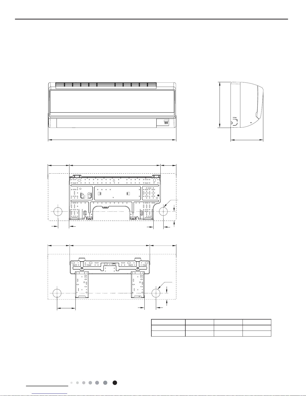
3. Outline Dimension Diagram
3.1 Indoor Unit
Modle W H D
07/09/12K 770 283 201
18K 865 305 215
W
120
66
93
150
542
161
71
173
548 102
2XΦ55
2XΦ55
H
41.3
40
D
07/09/12K:
18K:
Unit:mm
6
Technical Information
Service Manual
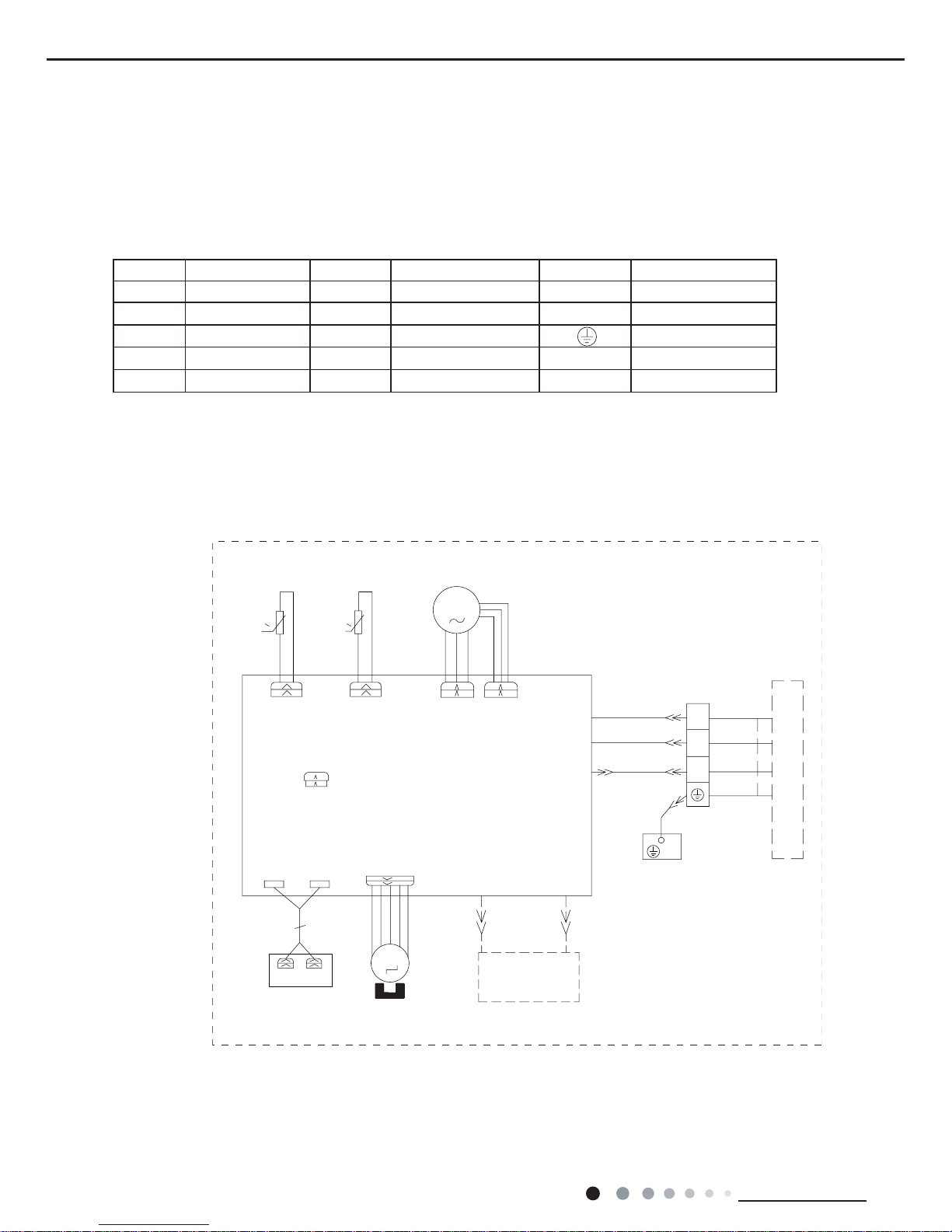
4. Electrical Part
4.1 Wiring Diagram
● Indoor Unit
●Instruction
Symbol Symbol Color Symbol Symbol Color Symbol Name
WH White GN Green CAP Jumper cap
YE Yellow BN Brown COMP Compressor
RD Red BU Blue Grounding wire
YEGN Yellow/Green BK Black / /
VT Violet OG Orange / /
Note: Jumper cap is used to determine fan speed and the swing angle of horizontal lover for this model.
0
TUBE
ROOM
N
M2
N(1)
XT
BU
3
YEGN
2
RT1
DISP1
0
RT2
BK
BN
PE
YEGN
COM-OUT
BK
BN
BU
AP1
AC-L
DISP2
SWING-UD
PGF
M1
PG
MOTOR
FAN
TEM.SENSOR
ROOM
TEM.SENSOR
TUBE
OUTDOOR UNIT
DISPLAY
SWING
MOTOR
EVAPORATOR
AP2
HEALTH-NHEALTH-L
COOL PLASMA
GENERATOR
BU
RD
(optional)
JUMP
CAP
07/09/12K
7
Technical Information
Service Manual
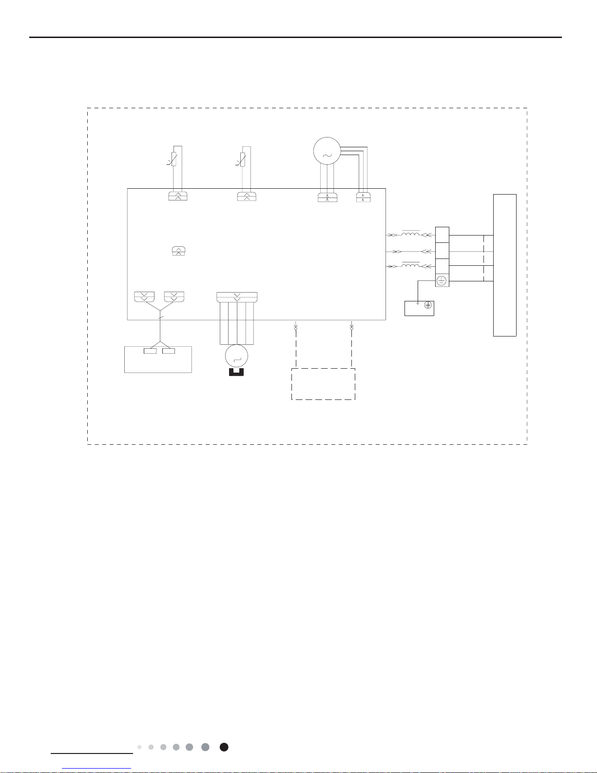
These wiring diagrams are subject to change without notice; please refer to the one supplied with the unit.
AC-L
3BK
TEM.SENSOR
TEM.SENSOR
PE
BK
ROOM
TUBE
M2
SWING-UD
RT2
AP2
2BN
PG
4YEGN
0
M1
1BU
FAN
OUTDOOR UNIT
BN
2
YEGN
3
BU
XT
N(1)
TUBE
ROOM
0
RT1
SWING
MOTOR
COM-OUT
N
PGF
MOTOR
CAP
JUMP
DISP2
DISP1
AP1
RECEIVER AND
DISPLAY BOARD
BU
RD
HEALTH-N
HEALTH-L
GENERATOR
COOL PLASMA
NOTE:The parts with broken line is applicable
to the models with COOL PLASMA GENERATOR
EVAPORATOR
18K
8
Technical Information
Service Manual
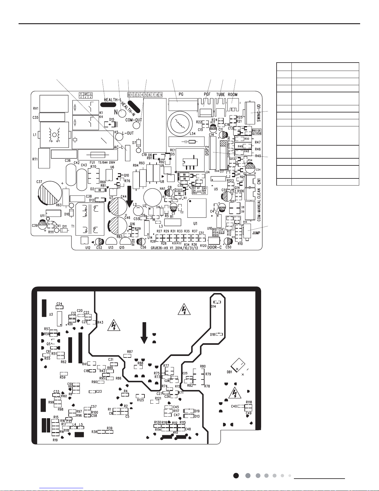
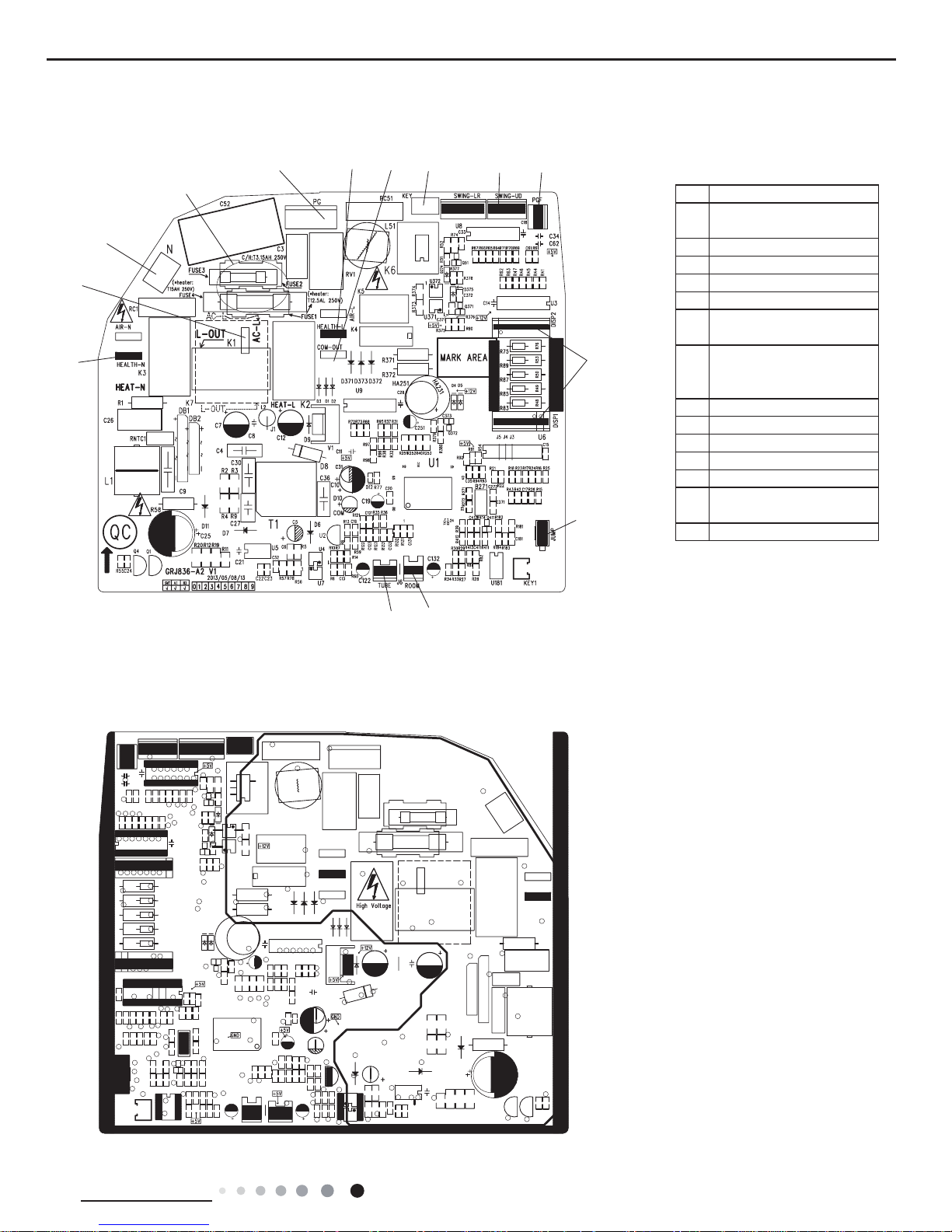
4.2 PCB Printed Diagram
● Top view
● Bottom view
(1) 07/09/12K
No. Name
1 Jumper cap
2 Display interface 1, 2
3 Up&down swing
4
Ambient temperature
sensor
5 Tube temperature sensor
6 PG feedback interface
7 PG motor interface
8
Communication interface
between live wire and
neutral wire
9
Neutral wire for healthy
function
10 Interface of neutral wire
11
Live wire for healthy
function
12 Interface of live wire
1
2
3
456
78
91011
12
9
Technical Information
Service Manual
● Top view
● Bottom view
(2) 18K
No. Name
1
Interface of health function
neutral wire
2 Interface of live wire
3 Neutral wire
4 Fuse
5 PG motor
6
Interface of health function
live wire
7
Communication interface
between indoor unit and
outdoor unit
8 Auto button
9 Up&down swing
10 PG feedback
11 Display interface
12 Jumper cap
13
Ambient temperature
sensor
14 Tube temperature sensor
1
2
3
4
5
6
7
8
9
10
11
12
13
14
10
Technical Information
Service Manual
5. Function and Control
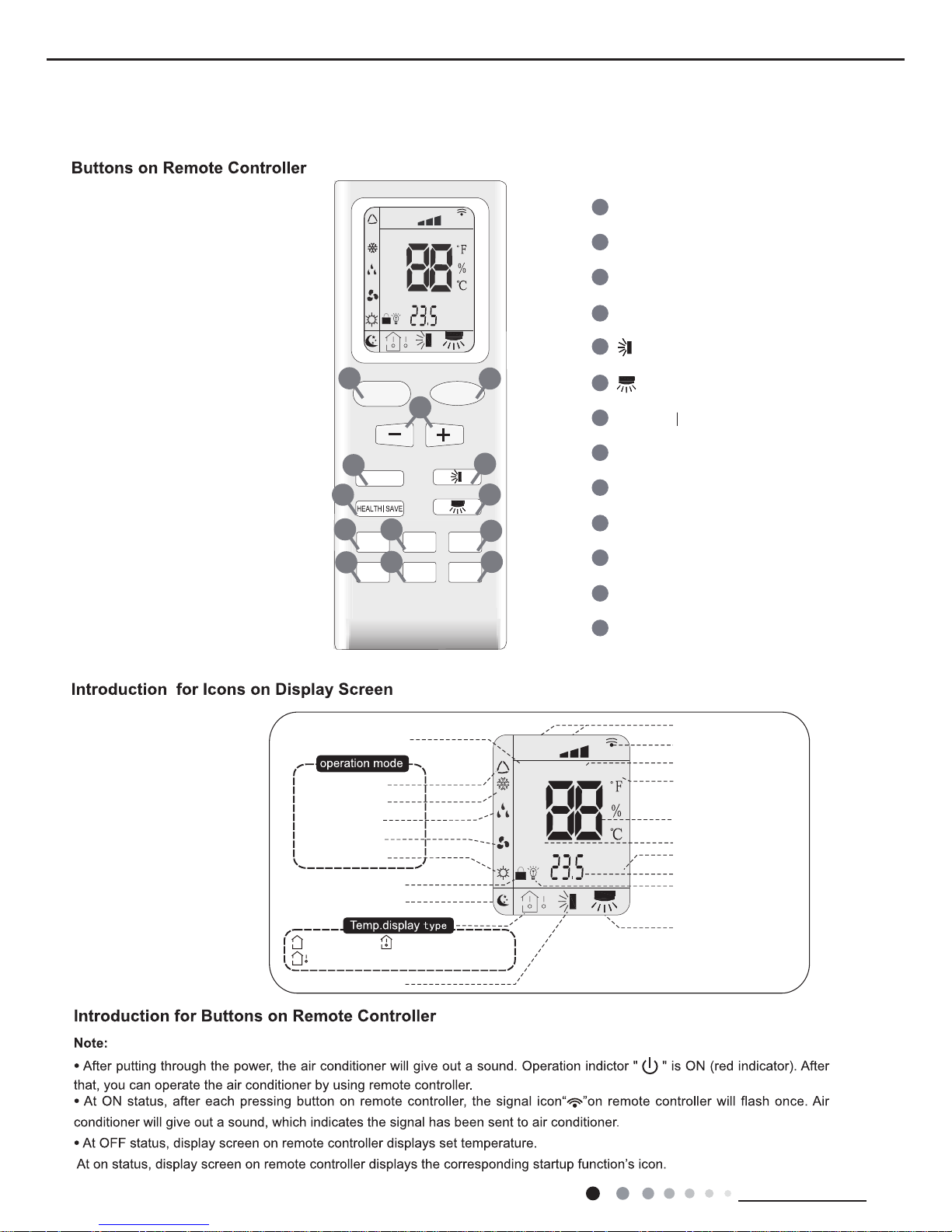
5.1 Remote Controller Introduction
ON/OFF Button
2
3
1
5
6
4
9
10
8
12
13
11
MODE Button
+/- Button
X-FAN Button
TEMP Button
TURBO Button
SLEEP Button
LIGHT Button
Button
HEALTH SAVE Button
7
Button
TIMER Button
FAN Button
FAN
AUTO
OPER
HEALTH
AIR
FILTER
TURBO
ON/OFF
X-FAN
HOUR
HUMIDITY
ON/OFF
MODE
FAN
X-FAN
TURBO
TEMP
TIMER
SLEEP
LIGHT
2
10
7
9
12
8
3
11
6
5
13
4
1
Child lock
Left&right swing
Sleep mode
Auto mode
Air mode
Cool mode
Heat mode
Fan mode
Dry mode
Up&down swing
:Indoor ambient temp.:Set temp.
:Outdoor ambient tep.
FAN
OPER
AUTO
HEALTH
AIR
FILTER
TURBO
ON/OFF
X-FAN
HOUR
HUMIDITY
TIMER ON/TIMER OFF
Set time
Light
Send signal
Sleep mode
X-fan
Set fan speed
Set temperature
Turbo mode
Temp. display type
Operation mode
11
Technical Information
Service Manual
AUTO COOL DRY FAN HEAT
Auto
no display
(horizontal louvers
stops at current position)
high speed.
5.
Under unit off status, press “+” button and button simultaneously to switch between simple swing setting and fixed-angle swing setting.
During switching the two swing settings, icon will blink for 2s.
12
Technical Information
Service Manual
no display
no display
(swing angle is
displayed dynamically)
(horizontal louvers
stops at current position)
(swing angle is
displayed dynamically)
Under unit off status, press “+” button and button simultaneously to switch between simple swing setting and fixed-angle swing setting.
During switching the two swing settings, icon will blink for 2s.
(Note:Health function is not available for some models.)
13
Technical Information
Service Manual
Signal sender
Battery
Cover of
battery box
Remove
Reinstall
14
Technical Information
Service Manual
5.2 Brief Description of Modes and Functions
A
B
C
B
C
A
1.Cooling Only
(1) Under this mode, fan and swing run at preset status, the temperature setting range is 16-30ć.
(2) Under malfunction for outdoor unit and protection stop, the indoor unit runs with the original status, and display malfunction.
(3) The indoor fan stops when the modes conflict with each other.
2. Dry Mode
(1) Under this mode, the indoor fan runs with low speed, and swing runs at preset status, the temperature setting range is 16-30
(2) Under malfunction for outdoor unit and protection stop, the indoor unit runs with the original status, and display malfunction.
3. Heating Mode
(1) Under this mode, the temperature setting range is 16-30ć.
(2) Working condition and Process of Heating
When the unit is ON and in heating mode, indoor fan starts cold air prevention operation; when the unit is off and the
indoor fan stopped before, it blows residual heat.
(3) Protection Function. The compressor stops as the malfunction (including any temperature sensor malfunction) in
heating mode, the indoor fan runs with blowing residual heat
(4) Defrosting and Oil Return
Once defrosting singnal of outdoor unit is received,Heating indicator on indoor unit OFF 0.5s and ON 10s.
ć.
4. Working Methods of Auto Mode
(1) When Tamb.≥26ć
, it operates in Cool mode.
(2) For heat pump unit, when Tamb.≤22ć, it operates in Heat mode.
(3) When 22ć< Tamb.< 26ć, it operates in auto fan mode upon initial startup of the unit. When changing to auto mode from
other modes, it will keep the previous operation mode (when it enter Dry mode, it operates in auto fan mode.).
5. Fan Mode
Only indoor fan operates in Fan mode. Under auto fan speed, it runs in cooling auto fan mode.
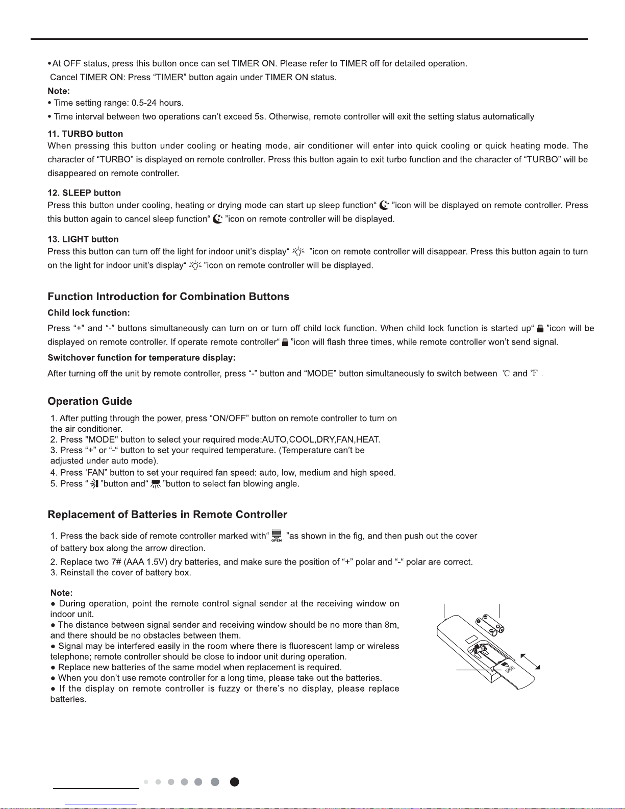
I. Basic Operation Mode
1. Cool; 2.Dry; 3.Heat; 4.Auto; 5.Fan
II. Basic Functions
indoor temperature---target temperature
target temperature---indoor temperature
With compressor capacity supplied
With no compressor capacity supplied
Cooling
operation
Heating
operation
Cooling
operation

15
Technical Information
Service Manual
1. Buzzer
The buzzer will give out a beep when the controller is energized, receiving signal from remote controller and auto button.
2. Auto Button
Press this button once, it will operate in Auto mode, and indoor fan operates in Auto fan mode and swing. When the unit is on,
pressing this button will turn off the unit.
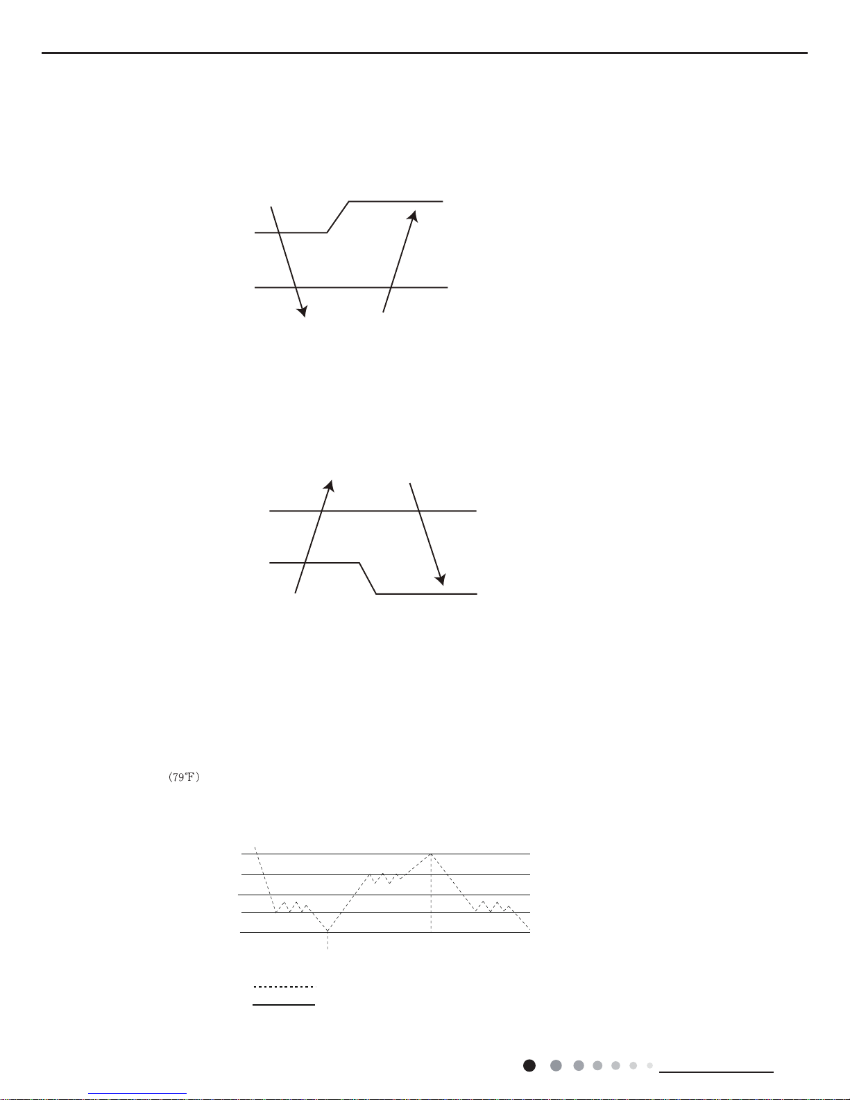
3. Auto Fan
a. Auto fan speed under heating mode
When Tinddor amb. ≤Tpreset+1℃, indoor fan operates at high speed;
When Tpreset+1℃<T inddor amb.<Tpreset+3℃, indoor fan operates at medium speed;
When T inddor amb.≥Tpreset+3℃, indoor fan operates at low speed.
b. Auto fan speed under cooling or fan mode
WhenT amb.≥Tpreset+3℃, indoor fan operates at high speed;
When Tpreset+1<T amb.<Tpreset+3℃, indoor fan operates at medium speed;
WhenT amb.≤Tpreset+1℃, indoor fan operates at low speed.
c. Auto fan speed under drying mode is low speed.
During auto fan speed, there’s should be at least 3min and 30s operation time when switching between high speed, medium
speed and low speed.
4. Sleep
5. Timer Function
(1) General Timer:
1.1 Time On: if Timer On is set when the system is,the controller will operate in the original setting mode after reaching the
timer on time. The timer interval is 0.5h, and the setting range is 0.5-24h.
1.2 Timer Off: Timer Off can be set when the unit is on. The unit will be off when timer off time is reahced. The timer
interval is 0.5h, and the setting range is 0.5-24h.
(2) Clock Timer:
2.1 Timer On: If Timer On is set when the system runs, it will continue to run; if Timer On is set when the system is off, the
system will start to run in the original setting mode when timer on time is reached.
2.2 Timer Off: If timer off is set when the system is off, the system keeps stand-by status; if timer off is set when the system
is on, the system stops when reaching timer off time.
III. Other Control
Sleep mode is only valid under cooling mode and heating mode;
Cooling mode: Basing on the set temperature of remote controller, after turning on the sleep function for a few hours, set
temperature will increase properly and automatically according to human body’s comfort.
Heating mode: Basing on the set temperature of remote controller, after turning on the sleep function for a few hours, set
temperature will decrease properly and automatically according to human body’s comfort.
2.3 Timer Change
Timer On and Timer OFF can be set via remote ON/OFF button. Timer time can be reset and the system will operate according to
the latest setting.
When the unit is on and Timer On and Timer Off are both set, the system will operate according to the set state. When the timer off
time is reached, the system will stop.
When the system stops, and Timer On and Timer Off are both set, the system will remain stop until timer on time is reached. After
that, the unit will operate according to the set mode everyday when the timer on time is reached. When the timer off time is reached,
the system will stop. If timer on time is the same as timer off time, the system will stop.
6. Memory Function
Memory contents: mode, up& down swing, light, set temperature, set fan speed, general timer (but clock timer). After power failure, if
the unit is reenergized, it will operate according to memory contents. If Timer function is not set in the last remote control, the system
will operate according to the last remote control.
If general timer function is set in the last remote control and power failure occurs before timer time is reached, the unit will operate
according to the timer function set in the last remote control. Timer time is calculated after the unit is re-energized.
If general timer function is set in the last remote control and power failure occurs after timer time is reached, the system will operate
according to the memory content before power failure. Timer operation is not memorized.
 Loading...