

Gree GWC12KF-K3DNA5A, GWC09KF-K3DNA5A, GWH12KF-K3DNA6A, GWH09KF-K3DNB1A, GWH12KF-K3DNB1A Service Manual
...
GREE ELECTRIC APPLIANCES,INC.OF ZHUHAI
Service Manual
MODEL:
(Refrigerant R410A)
GWC09KF-K3DNA5A GWC12KF-K3DNA5A
GWH09KF-K3DNA5A GWH12KF-K3DNA5A
GWH09KF-K3DNA6A GWH12KF-K3DNA6A
GWH09KF-K3DNB1A GWH12KF-K3DNB1A

Table of Contents
Summary and features..................................................................................1
Part 1 Safety Precautions
..........................................................................................2
Part 2 Specifications.....................................................................................................3
2.1 Unit Specifications..................................................................................................3
2.3 CapacityVariation Ratio AccordingtoTemperature...............................................11
2.2 Operation Characteristic Curve............................................................................11
2.4 Operation Date.....................................................................................................12
2.5 Noise criteria curve tables for both models..........................................................12
Part 3 Construction Views
......................................................................................13
3.1 Indoor Unit ...........................................................................................................13
3.2 Outdoor Unit ........................................................................................................14
Part 4 Refrigerant System Diagram
...................................................................15
5.1 Electrical Data......................................................................................................16
5.2 Electrical Wiring....................................................................................................16
5.3 Printed Circuit Board............................................................................................18
Part 5 Schematic Diagram
......................................................................................16
6.1 Remote Control Operations..................................................................................23
6.2 Changing Batteries and Notices ..........................................................................25
6.3 Description of Each Control Operation.................................................................26
6.4
.....................................................28
6.5 Frequency Control................................................................................................28
6.6 3-minutes Standby...............................................................................................28
6.7 Compressor Protection Function..........................................................................28
6.8 Discharge Pipe Control........................................................................................29
6.9 Input Current Control............................................................................................29
6.10 Freeze-up Protection Control.............................................................................29
6.11 Heating Peak-cut Control...................................................................................30
6.12 Defrost Control...................................................................................................30
6.13 Fan Control........................................................................................................31
Part 6 Function and Control
...................................................................................23
Troubleshooting of Temp Sensor Malfunction

Table of Contents
Part 8 Exploded Views and Parts List
..............................................................38
Part 9 Troubleshooting...............................................................................................53
9.1
Precautions Before Performing Inspection or Repair
...........................................53
9.2
Confirmation
.........................................................................................................53
9.3
Judgement by Flashing LED of Indoor/Outdoor Unit
...........................................53
9.4
How to Check Simply the Main Part
.....................................................................55
9.5
2-way, 3-way Valve Appearance
..........................................................................59
8.1 Indoor unit.............................................................................................................38
8.2 Outdoor unit..........................................................................................................45
Part10 Removal Procedure.......................................................................................66
10.1
Removal Procedure of Indoor Unit
.....................................................................66
10.2
Removal Procedure of Outdoor Unit
...................................................................80
Part 7 Installation Manual
........................................................................................32
7.3 Install Indoor Unit.................................................................................................32
7.2 Installation Position Selection..............................................................................32
7.1 Tools Required for Installation.............................................................................32
7.4 Install Outdoor Unit ..............................................................................................36
7.5 Test Operation......................................................................................................37
1
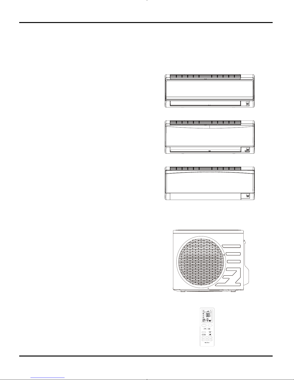
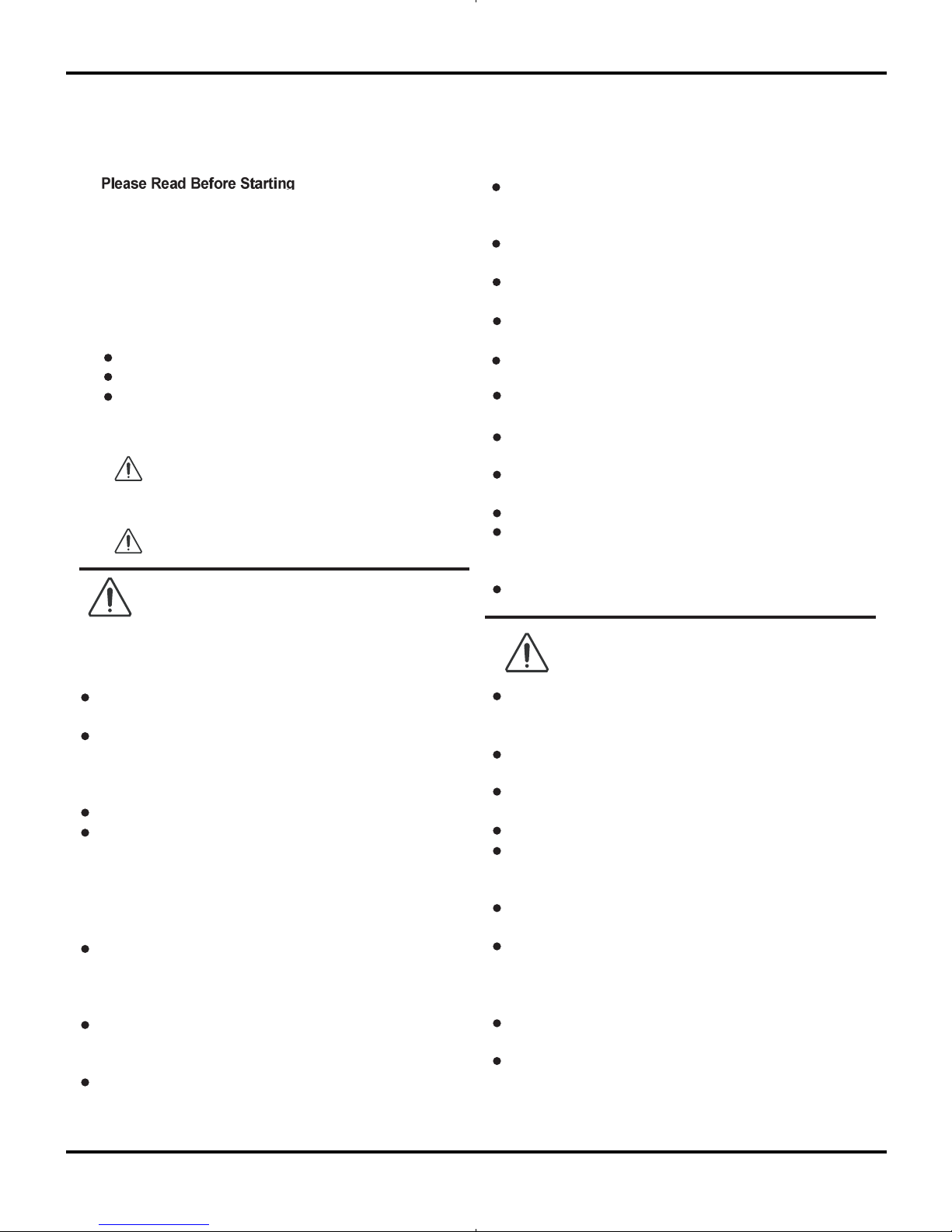
Summary and features
Indoor Unit
GWC09KF-K3DNA5A/I
GWH09KF-K3DNA5A/I
GWC12KF-K3DNA5A/I
GWH12KF-K3DNA5A/I
Outdoor Unit
GWC09KF-K3DNA5A/O
GWH09KF-K3DNA5A/O
GWC12KF-K3DNA5A/O
GWH12KF-K3DNA5A/O
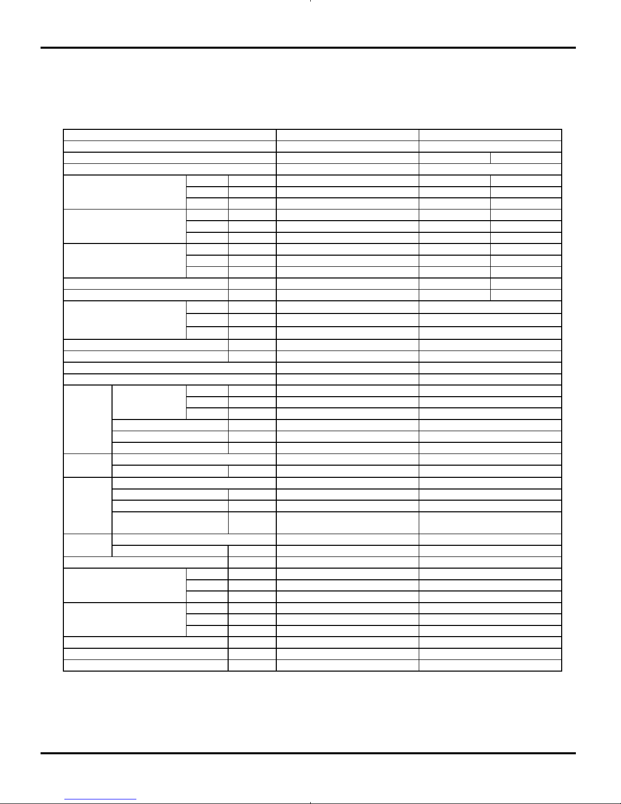
Remote control window
YB1F2
Summary and features
GWH09KF-K3DNA6A/I
GWH12KF-K3DNA6A/I
FAN
AUTO
OPER
HEALTH
AIR
FILTER
TURBO
ON/OFF
X-FAN
HOUR
HUMIDITY
ON/OFF
MODE
FAN
X-FAN
TURBO
TEMP
TIMER
SLEEP
LIGHT
GWH09KF-K3DNB1A/I
GWH12KF-K3DNB1A/I
2
1.Safety Precautions
Safety Precautions
Important!
This air conditioning system meets strict safety and
operating standards. As the installer or service person,
it is an important part of your job to install or service the
system so it operates safely and efficiently.
Follow each installation or repair step exactly as shown.
Observe all local, state, and national electrical codes.
Pay close attention to all warning and caution notices
given in this manual.
To prevent injury to the user or other people and
property damage, the following instructions must
be followed.
About the pict
ures:
Erroneous handing gives a high possi-
bility to induce serious results such as
death or heavy injury.
Erroneous handing may induce serious
injury depending on the situation.
Do not supply power to the unit until all wiring and tubing
are completed or reconnected and checked.
Highly dangerous electrical voltages are used in this
system. Carefully refer to the wiring diagram and these
instructions when wiring. Improper connections and inad-
equate grounding can cause accidental injury or death.
Ground the unit following local electrical codes.
Connect all wiring tightly. Loose wiring may cause over-
heating at connection points and a possible fire hazard.
All electric work must be performed by licensed technician,
ac-
cording to local regulations and the instructions given in this
manual.
There is risk of fire, electric shock, explosion, or injury.
Ask your dealer or specialized subcontractor for installation or
repair work.
Make sure the ceiling/wall is strong enough to hold the
unit’s weight. The outdoor unit should be installed in a
location where air and noise emitted by the unit will not
disturb the neighbo
rs.
Properly insulate any tubing run inside a room to prevent
"sweating" that can cause dripping and water damage to
walls and floors.
The outdoor unit must be installed on stable, level surface,
in a place where there is no accumulation of snow, leaves
or rubbish.
The unit should be installed according to the instructions
in order to minimize the risk of damage from earthquakes,
typhoons or strong winds.
When the refrigerant touches the fire etc., it was decomposed
and a poisonous gas is generated.
Use only the specified refrigerant to charge the re
frigerant
circuit.
Do not mix it with any other refrigerant and do not allow air to
remain in the circuit.
Air enclosed in the circuit can cause high pressure resulting
in a rupture and other hazards.
After completing installation work, make sure that refriger-
ant gas has not leaked.
The limit density is made not to be exceeded even if the refrig-
erant leaks by any chance.
Turn the power off at the main power box (mains) before open-
ing the unit to check or repair electrical parts and wiring.
Keep your fingers and clothing away from any moving parts.
Clean up the site after you finish, remembering to check that
no metal scraps or bits of wiring have been left inside the unit
being serviced.
The unit must be properly earth connected.
Caution
Warning
Warning
Caution
Never install on the place where a combustible gas might
leak. The gas may ignite or explode when the gas leaks and
collects in surround of the unit.
When the unit is installed at telecommunication centers or
hospitals, take a proper provision against noise.
When installing at a watery place, provide an electric leak
breaker.
Do not wash the unit with water.
Be very careful about unit transportation. The unit should not
be carried by only one person if it is more than 20kg. It occasionally causes the damage of the unit and health to be impaired.
Do not touch the heat exchanger fins w
ith your hands.
Doing so may cut your hands.
Do not touch the compressor or refrigerant piping w
ithout
wearing glove on your hands. Touching directly such part can
cause a burn or frostbite as it becomes high or low temperature
according to the refrigerant state.
Do not operate the air conditioner without the air filter set
place. Dust may accumulate, and cause a failure.
At emergency (if you smell something burning), stop opera-
tion and turn the power source switch off.
3
2.Specifications
Remarks:
Rated conditions are:
Cooling: Indoor air temperature 27°C D.B. / 19°C W.B.
Outdoor air temperature 35°C D.B. / 24°C W.B.
Heating: Indoor air temperature 20°C D.B.
Outdoor air temperature 7°C D.B. / 6°C W.B.
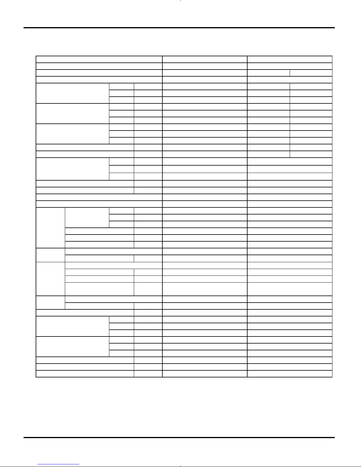
2.1 Unit Specifications
Models GWC09KF-K3DNA5A, GWH09KF-K3DNA5A
Specifications
COOLING HEATING
High Hz 78 98
Standard Hz 53 72
Low Hz 15 24
High W / Btu/h 3230 / 11000 4100 / 14000
Standard W / Btu/h 2650 / 9000 3520 / 12000
Low W / Btu/h 450 / 1500 450 / 1500
High W 1350 1450
Standard W 800 950
Low W 200 200
W 1420 1550
A6.36.8
H
m
3
/h
M
m
3
/h
L
m
3
/h
l/h
W/W
Hr/min
Mr/min
Lr/min
W
μF
A
mm
mm
mm
mm
W
A
HdB (A)
MdB (A)
LdB (A)
HdB (A)
MdB (A)
LdB (A)
mm
mm
kg
610X294X24
8/11
38
48
770X283X201
844X342X261
24
40
34
30
MP24 BA
1.5
PCB 3.15A
1.2
0.16
Cro ss flow fa n
Φ92X594
Aluminum fin-copper tube
7
2-1.4
8/11
GWH09KF-K3DNA5A
220-240V
~
600
0.8
3.3/3.7
A/A
GWH09KF-K3DN A5A/I
1100
10
844X342X261
24
40
34
38
48
30
770X283X201
1.2
700
1.5
PCB 3.15A
610X294X24
MP24 BA
0.16
Cross flow fan
Φ92X594
Aluminum fin-copper tube
A/A
GWC09KF-K3DNA5A/I
1100
10
900
GWC09KF-K3DNA5A
220-240V
~
600
0.8
1420
6.3
800
2650 / 9000
450 / 1500
COOLING
Model
Function
Rated Voltage
Rated Input
Frequency
(Inverter different Compress or
speed)
Total Capacity
(Inverter different Compress or
speed)
Power Input
(Inverter different Compress or
speed)
78
3230 / 11000
200
1350
53
15
Ai r F low Vol u m e
Rated Current
Fus e (A)
Dimension (WXHXD) ( mm)
Fan
Evaporator
Swing
Mo tor
Coil length (l)Xheigh
t
(H)Xcoil width (L)
Output
Type
Dimension of Package (LXWXH)
Net Weight /Gross Weight
Output
Capacitor
RLA
Diameter-Length
Pipe Diameter
Row-Fin Gap
Sound Pressure Level
Sound Power Level
700
Dehumidifying Volume
7
2-1.4
Energy Class
EER / C.O.P
Speed
Fan Motor
Indoor unit
3.3
CB14600050 CB14600051 CB14600060 CB14600063Product Code
Model
370
280
370
280
900
4
The above data is subject to change without notice. Please refer to the nameplate of the unit.
GWC09KF-K3DNA5A/O GWH09KF-K3DNA5A/O
Manufacturer/tradem ark DIT/daikin DIT/daiki n
1YC23AEXD 1YC23AEXD
L.R.A. (A) A 4 4
R LA( A) A 4 4
Power Input(W) W 600 600
CS-7SA CS-7SA
Capillary Capillary
Transducer starting Transducer starting
℃
10~48 -15~48
Aluminum fin-copper tube Aluminum fin-copper tube
Pipe Diameter mm 7 7
Rows-Fin Gap mm 1-1.4 1-1.4
mm 647X528X19.05 647X528X19.05
Speed rpm 930 930
Output of Fan Motor W 30 30
RLA A 0.236 0.236
Capacitor μF2 2
m
3
/h
1600 1600
AXial fan AXial fan
Diameter mm 370 370
/ Auto defrosting
T1 T1
II
IP24 IP24
Mp a 3 .8 3 .8
Mp a 1 .2 1 .2
dB (A) 51 51
dB (A) 61 61
mm 710X550X275 710X550X275
mm 771X348X592 771X348X592
kg 27/31 28/32
R410A R410A
Weight kg 0.74 0.74
Length (m) m
55
Gas additional charge g/m
15 20
Liquid Pipe Diameter mm
Φ6 Φ6
Gas Pipe Diameter mm
Φ9.52 Φ9.52
m10 10
m15 15
Starting Method
Type
Defrosting Method
Overload Protector
Air Flow Volume of Outdoor Unit
Outdoor Unit
Compressor
Fan
Fan Motor
Working Temp Range
Heat
EXchanger
Coil
Coil
Model
Coil length (l) X height (H) X coil width (L)
Thro ttlin g Method
Mois ture Protection
Permissible EXcessive Operating
Pressure for the Discharge Side
Permissible EXcessive Operating
Pressure for the Suction Side
Type
Climate Type
Isolation
Dimension (WXHXD)
Dimension of Package (LXWXH)
Sound Press ure Level
Sound Power Level
Net Weight /Gross Weight
Connection
Pipe
MaX. Interunit Piping Length
MaX. Interunit Height Difference
Refrigerant
Name of refrigerant
Specifications
Rotary type
Rotary type
5
Remarks:
Rated conditions are:
Cooling: Indoor air temperature 27°C D.B. / 19°C W.B.
Outdoor air temperature 35°C D.B. / 24°C W.B.
Heating: Indoor air temperature 20°C D.B.
Outdoor air temperature 7°C D.B. / 6°C W.B.
Models GWC12KF-K3DNA5A, GWH12KF-K3DNA5A
Specifications
COOLING HEATING
High Hz 92 108
Standard Hz 72 78
Low Hz 15 24
High W / Btu/h 3960 / 13500 5130 / 17500
Standard W / Btu/h 3530 / 12000 4100 / 13990
Low W / Btu/h 600 / 2000 600 / 2000
High W 1450 1550
Standard W 1100 1135
Low W 220 220
W 1550 1650
A6.57.8
H
m
3
/h
M
m
3
/h
L
m
3
/h
l/h
W/W
Hr/min
Mr/min
Lr/min
W
μF
A
mm
mm
mm
mm
W
A
HdB (A)
MdB (A)
LdB (A)
HdB (A)
MdB (A)
LdB (A)
mm
mm
kg
CB14600070 CB14600072 CB14600080 CB14600083
Model
410
300
410
300
950
750
Dehumidifying Volum e
7
2-1.4
610X294X24
Energy Class
EER / C.O.P
Speed
Fan Motor
Indoor unit
3.21
Dimension of Package (LXWXH)
Net Weight /Gross W eight
Output
Capacitor
RLA
Diameter-Length
Pipe Diameter
Row-Fin Gap
Sound Pressure Level
Sound Power Level
Air Flow Volume
Rated Current
Fuse (A)
Dimension (W XHXD) ( mm)
Fan
Evaporator
Swing
Motor
Coil length (l)Xheight (H)Xcoil
width (L)
Output
Type
92
3960 / 13500
220
1450
72
15
Model
Function
Rated Voltage
Rated Input
Frequency
(Inverter different Compressor
speed)
Total Capacity
(Inverter different Compressor
speed)
Power Input
(Inverter different Compressor
speed)
Product Code
GWC12KF-K3DNA5A
220-240V
~
680
1.5
1550
6.5
1100
3530 / 12000
600 / 2000
COOLING
A/A
GWC12KF-K3DNA5A/I
1150
10
950
1.2
750
1.5
PCB 3.15A
MP24BA
0.16
Cross flow fan
Φ92X594
Aluminum fin-copper tube
39
49
31
770X283X201
844X342X261
25
41
35
9/12
GWH12KF-K3DNA5A
220-240V
~
680
1.5
3.21/3.61
A/A
GWH12KF-K3DNA5A/I
1150
10
MP24BA
1.5
PCB 3.15A
1.2
0.16
Cross flow fan
Φ92X594
Aluminum fin-copper tube
7
2-1.4
610X294X24
9/12
39
49
770X283X201
844X342X261
25
41
35
31
6
GWC12KF-K3DNA5A/O GWH12KF-K3DNA5A/O
Manufacturer/tradem ark DIT/daikin DIT/daiki n
1YC23AEXD 1YC23AEXD
L.R.A. (A) A 4 4
R LA( A) A 4 4
Power Input(W) W 600 600
CS-7SA CS-7SA
Capillary Capillary
Transducer starting Transducer starting
℃
10~48 -15~48
Aluminum fin-copper tube Aluminum fin-copper tube
Pipe Diameter mm 7 7
Rows-Fin Gap mm 2-1.4 2-1.4
mm 647X528X38.1 647X528X38.1
Speed rpm 930 930
Output of Fan Motor W 30 30
RLA A 0.236 0.236
Capacitor μF2 2
m
3
/h
1600 1600
Axial fan Axial fan
Diameter mm 370 370
/
Auto defrosting
T1 T1
II
IP24 IP24
Mp a 3 .8 3 .8
Mp a 1 .2 1 .2
dB (A) 53 53
dB (A) 63 63
mm 710X550X275 710X550X275
mm 771X348X592 771X348X592
kg 29/33 30/34
R410A R410A
Weight kg 1.0 1.0
Length (m) m
55
Gas additional charge g/m
15 20
Liquid Pipe Diameter mm
Φ6 Φ6
Gas Pipe Diameter mm
Φ9.52 Φ9.52
m10 10
m20 20
Net Weight /Gross Weight
Connection
Pipe
Max. Interunit Piping Length
Max. Interunit Height Difference
Refrigerant
Name of refrigerant
Dimension (WXHXD)
Dimension of Package (LXWXH)
Sound Press ure Level
Sound Power Level
Mois ture Protection
Permissible Excessive Operating
Pressure for the Discharge Side
Permissible Excessive Operating
Pressure for the Suction Side
Type-Piece
Climate Type
Isolation
Outdoor Unit
Compressor
Fan
Fan Motor
Working Temp Range
Heat
Exchanger
Coil
Coil
Model
Coil length (l) x height (H) x coil width (L)
Thro ttlin g Method
Starting Method
Type
Defrosting Method
Overload Protector
Air Flow Volume of Outdoor Unit
Specifications
The above data is subject to change without notice. Please refer to the nameplate of the unit.
Rotary type
Rotary type
7
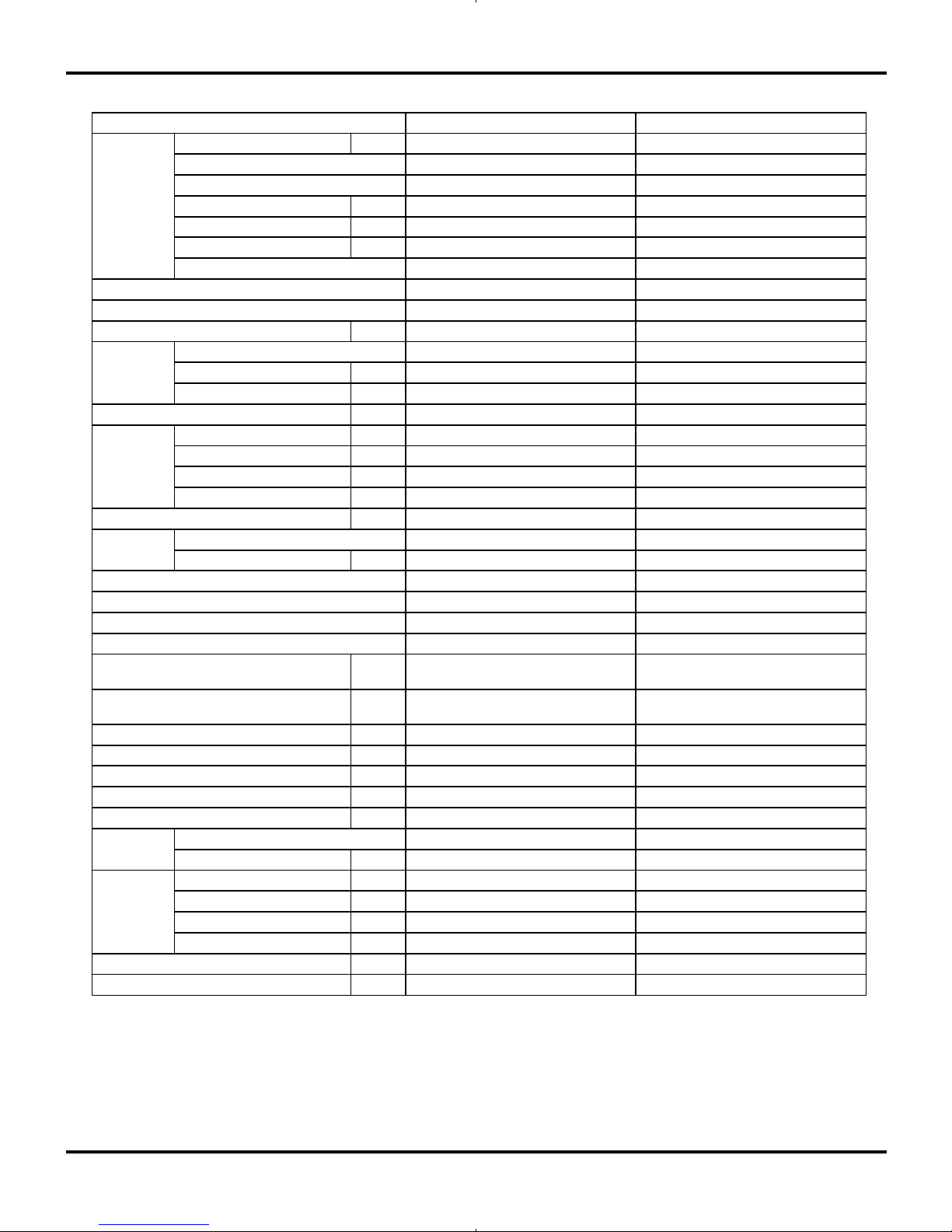
Models GWH09KF-K3DNA6A, GWH12KF-K3DNA6A
Specifications
GWH09KF-K3DNA6A GW H12KF-K3DNA6A
CB146
00110 CB14600120
Rated Voltage V
~
220-240 220-240
Rated Frequency Hz 50 50
Phases 1 1
Indoor Indoor
W 2650(450~3230) 3530(600~3960)
W 3520(450~4100) 4100(600~5130)
W 800(200~1350) 1100(220~1450)
W 950(200~1450) 1135(220~1550)
A 3.55 4.88
A 4.21 5.04
W 1550 1650
A 6.88 7.32
m
3
/h
600/520/370/280/- 680/560/410/300/-
L/h 1 1.2
W/W 3.3 3.21
W/W 3.7 3.61
W/W / /
W/W / /
m
2
12-18 16-24
Model of indoor unit GWH09KF-K3DNA6A/I GWH12KF-K3DNA6B/I
Fan Type Cross-flow Cross-flow
Diameter Length(DXL) mm Φ92X594 Φ92X594
Fan Motor Cooling Speed
(SH/H/M/L/SL)
r/min 1300/1100/900/700/- 1350/1150/950/750/-
Fan Motor Heating Speed
(SH/H/M/L/SL)
r/min 1300/1140/980/820/- 1350/1190/1020/850/-
Output of Fan Motor W 10 10
Fan Motor RLA A 0.16 0.16
Fan Motor Capacitor μF1.2 1.2
Input of Heater W 0 0
Evaporator Form Aluminum Fin-copper Tube Aluminum Fin-copper Tube
Pipe Diameter mm Φ7 Φ7
Row-fin Gap mm 2-1.4 2-1.4
Coil Length (LXDXW) mm 610X294X24 610X294X24
Swing Motor Model MP24BA MP24BA
Output of Swing Motor W 1.5
1.5
Fuse A PCB 3.15A
PCB 3.15A
Sound Pressure Level
(SH/H/M/L/SL)
dB (A) 41/38/30/24/- 42/39/31/25/-
Sound Power Level (SH/H/M/L/SL) dB (A) 51/48/40/34/- 52/49/41/35/-
Dimension (W XHXD) mm 770X283X201 770X283X201
Dimension of Carton Box (L/W/H) mm 841X339X246
841X339X246
Dimension of Package (L/W/H) mm 844X342X261
844X342X261
Net Weight kg 8 9
Gross Weight kg 11 12
SEER
HSPF
Application Area
Indoor Unit
Air Flow Volume(SH/H/M/L/SL)
Dehumidifying Volum e
EER
COP
Cooling Power Current
Heating Power Current
Rated Input
Rated Current
Cooling Capacity (Min~Max)
Heating Capacity (Min~Max)
Cooling Power Input (Min~Max)
Heating Power Input (Min~Max)
Model
Product Code
Power Supply
Power Supply Mode
8
Specifications
The above data is subject to change without notice. Please refer to the nameplate of the unit.
Model of Outdoor Unit GWH09KF-K3DNA5A/O GWH12KF-K3DNA5A/O
Compressor
Manufacturer/Trademark
Daikin Compressor Industries
/daikin
Daikin Compressor
Industries/daikin
Compressor Model 1YC23AEXD 1YC23AEXD
Compressor Oil DAPHEN FVC50K DAPHEN FVC50K
Compressor Type Rotary Rotary
L.R.A. A 4 4
Compressor RLA A 4 4
Compressor Power Input W 600W 600W
Overload Protector CS-7SA CS-7SA
Throttling Method Capillary Capillary
Operation temp
℃
16~30 16~30
Ambient temp (cooling)
℃
10~48 10~48
Ambient temp (heating)
℃
-15~24 -15~24
Condenser Form Aluminum Fin-copper Tube Aluminum Fin-copper Tube
Pipe Diameter mm Φ7 Φ7
Rows-fin Gap mm 1-1.4 2-1.4
Coil Length (LXDXW) mm 647X528X19.05 647X528X38.1
Fan Motor Speed rpm 930 930
Output of Fan Motor W 30 30
Fan Motor RLA A 0.236 0.236
Fan Motor Capacitor μF2 2
Air Flow Volume of Outdoor Unit
m
3
/h
1600 1600
Fan Type Axial-flow Axial-flow
Fan Diameter mm 370 370
Defrosting Method Automatic Defrosting Automatic Defrosting
Clim ate Type T1 T1
Isolation I I
Moisture Protection IP24 IP24
Permissible Excessive Operating
Pressure for the Discharge Side
MPa 3.8 3.8
Permissible Excessive Operating
Pressure for the Suction Side
MPa 1.2 1.2
Sound Pressure Level (H/M/L) dB (A) 51/-/- 53/-/-
Sound Power Level (H/M/L) dB (A) 61/-/- 63/-/-
Dimension (W XHXD) mm 658X550X275 658X550X275
Dimension of Carton Box (L/W/H) mm 768X345X577 768X345X577
Dimension of Package (L/W/H) mm 771X348X592 771X348X592
Net Weight kg 28 30
Gross Weight kg 32 34
Refrigerant R410A R410A
Refrigerant Charge kg 0.74 1
Length m 5 5
Gas Additional Charge g/m 30 20
Outer Diameter Liquid Pipe mm Φ6 Φ6
Outer Diameter Gas Pipe mm Φ9.52 Φ9.52
Max Distance Height m 10 10
Max Distance Length m 15 20
Outdoor Unit
Connection
Pipe
9
Specifications
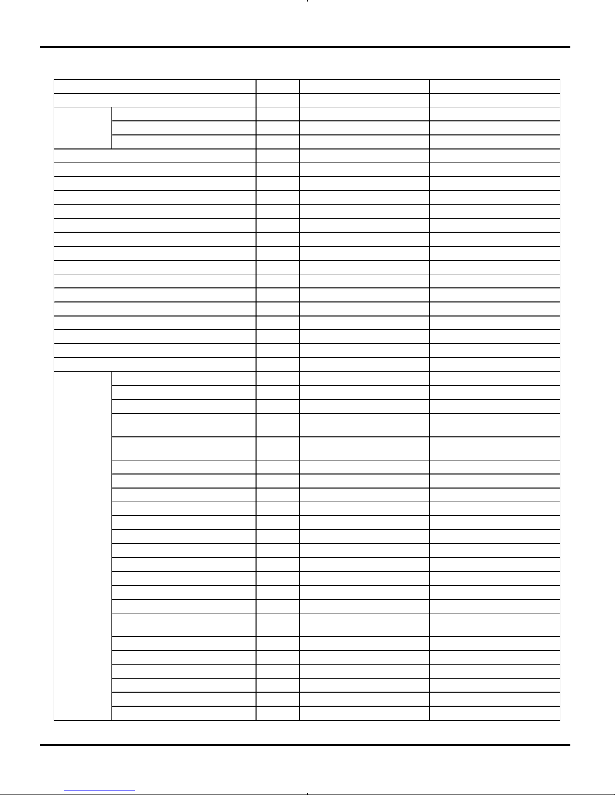
Models GWH09KF-K3DNB1A,GWH12KF-K3DNB1A
GWH09KF-K3DNB1A GW H12KF-K3DNB1A
CB14600760 CB14600770
Rated Voltage V
~
220-240 220-240
Rated Frequency Hz 50 50
Phases 1 1
Indoor Indoor
W 2650(450~3230) 3530(600~3960)
W 3520(450~4100) 4100(600~5130)
W 800(200~1350) 1100(220~1450)
W 950(200~1450) 1135(220~1550)
A 3.55 4.88
A 4.21 5.04
W 1550 1650
A 6.88 7.32
m
3
/h
600/520/370/280/- 680/560/410/300/-
L/h 1 1.2
W/W 3.3 3.21
W/W 3.7 3.61
W/W / /
W/W / /
m
2
12-18 16-24
Model of indoor unit GWH09KF-K3DNB1A/I GWH12KF-K3DNB1A/I
Fan Type Cross-flow Cross-flow
Diameter Length(DXL) mm Φ92X594 Φ92X594
Fan Motor Cooling Speed
(SH/H/M/L/SL)
r/min 1300/1100/900/700/- 1350/1150/950/750/-
Fan Motor Heating Speed
(SH/H/M/L/SL)
r/min 1300/1140/980/820/- 1350/1190/1020/850/-
Output of Fan Motor W 10 10
Fan Motor RLA A 0.16 0.16
Fan Motor Capacitor μF1.2 1.2
Input of Heater W 0 0
Evaporator Form Aluminum Fin-copper Tube Aluminum Fin-copper Tube
Pipe Diameter mm Φ7 Φ7
Row-fin Gap mm 2-1.4 2-1.4
Coil Length (LXDXW) mm 610X294X24 610X294X24
Swing Motor Model MP24BA MP24BA
Output of Swing Motor W 1.5
1.5
Fuse A PCB 3.15A
PCB 3.15A
Sound Pressure Level
(SH/H/M/L/SL)
dB (A) 41/38/30/24/- 42/39/31/25/-
Sound Power Level (SH/H/M/L/SL) dB (A) 51/48/40/34/- 52/49/41/35/-
Dimension (W XHXD) mm 770X283X201 770X283X201
Dimension of Carton Box (L/W/H) mm 844X342X261
844X342X261
Dimension of Package (L/W/H) mm 847X345X276
847X345X276
Net Weight kg 8 9
Gross Weight kg 11 12
Model
Product Code
Power Supply
Power Supply Mode
Cooling Capacity (Min~Max)
Heating Capacity (Min~Max)
Cooling Power Input (Min~Max)
Heating Power Input (Min~Max)
Cooling Power Current
Heating Power Current
Rated Input
Rated Current
Air Flow Volume(SH/H/M/L/SL)
Dehumidifying Volum e
EER
COP
SEER
HSPF
Application Area
Indoor Unit
10
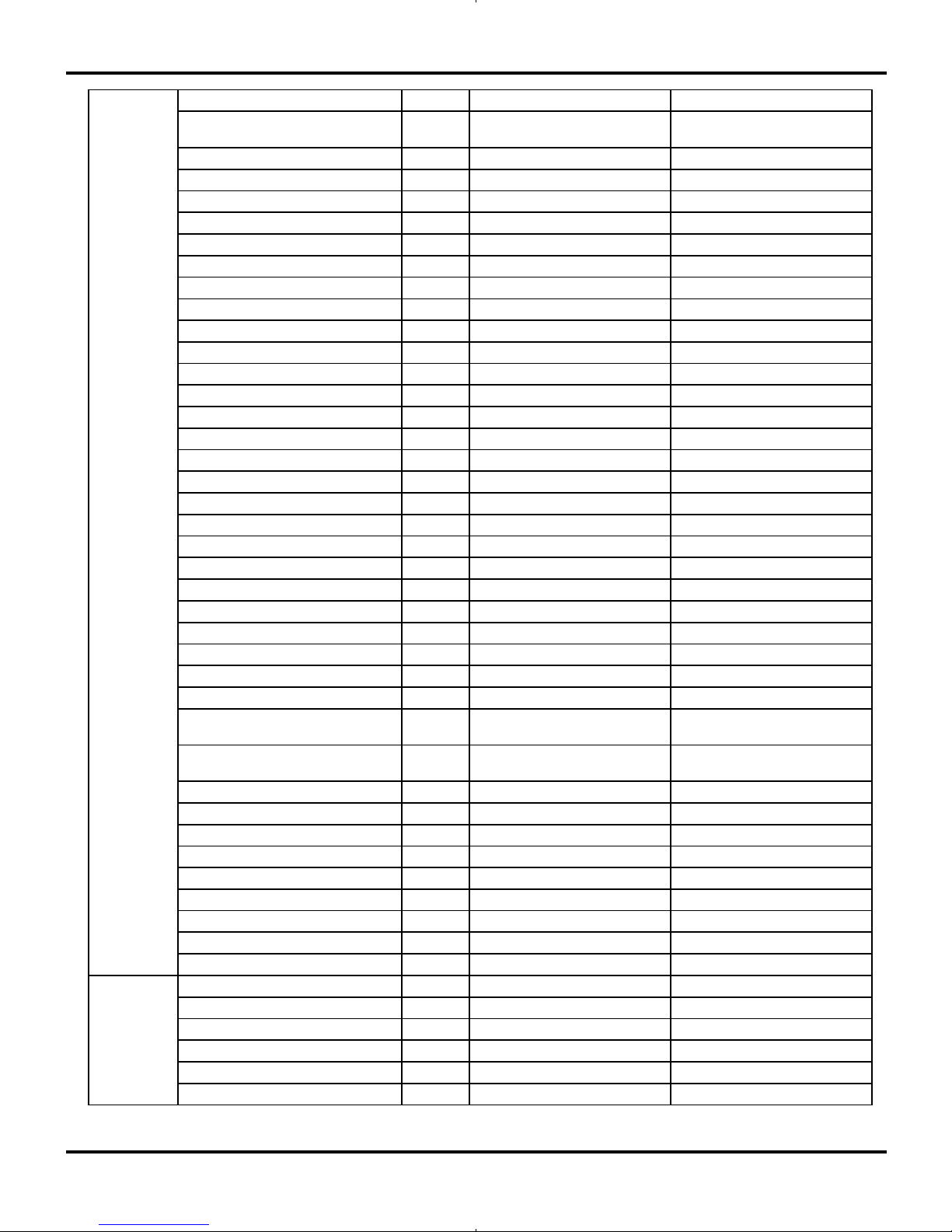
Specifications
The above data is subject to change without notice. Please refer to the nameplate of the unit.
Model of Outdoor Unit GWH09KF-K3DNA5A/O GWH12KF-K3DNA5A/O
Compressor
Manufacturer/Trademark
Daikin Compressor Industries
/daikin
Daikin Compressor
Industries/daikin
Compressor Model 1YC23AEXD 1YC23AEXD
Compressor Oil DAPHEN FVC50K DAPHEN FVC50K
Compressor Type Rotary Rotary
L.R.A. A 4 4
Compressor RLA A 4 4
Compressor Power Input W 600W 600W
Overload Protector CS-7SA CS-7SA
Throttling Method Capillary Capillary
Operation temp
℃
16~30 16~30
Ambient temp (cooling)
℃
18~43 18~43
Ambient temp (heating)
℃
-15~24 -15~24
Condenser Form Aluminum Fin-copper Tube Aluminum Fin-copper Tube
Pipe Diameter mm Φ7 Φ7
Rows-fin Gap mm 1-1.4 2-1.4
Coil Length (LXDXW) mm 647X528X19.05 647X528X38.1
Fan Motor Speed rpm 930 930
Output of Fan Motor W 30 30
Fan Motor RLA A 0.236 0.236
Fan Motor Capacitor μF2 2
Air Flow Volume of Outdoor Unit
m
3
/h
1600 1600
Fan Type Axial-flow Axial-flow
Fan Diameter mm 370 370
Defrosting Method Automatic Defrosting Automatic Defrosting
Climate Type T1 T1
Isolation I I
Moisture Protection IP24 IP24
Permissible Excessive Operating
Pressure for the Discharge Side
MPa 3.8 3.8
Permissible Excessive Operating
Pressure for the Suction Side
MPa 1.2 1.2
Sound Pressure Level (H/M/L) dB (A) 51/-/- 53/-/-
Sound Power Level (H/M/L) dB (A) 61/-/- 63/-/-
Dimension (W XHXD) mm 710X318X550 710X318X550
Dimension of Carton Box (L/W/H) mm 771X348X592 771X348X592
Dimension of Package (L/W/H) mm 774X351X607 774X351X607
Net Weight kg 28 30
Gross Weight kg 32 34
Refrigerant R410A R410A
Refrigerant Charge kg 0.74 1
Length m 5 5
Gas Additional Charge g/m 30 20
Outer Diameter Liquid Pipe mm Φ6 Φ6
Outer Diameter Gas Pipe mm Φ9.52 Φ9.52
Max Distance Height m 10 10
Max Distance Length m 15 20
Outdoor Unit
Connection
Pipe
11
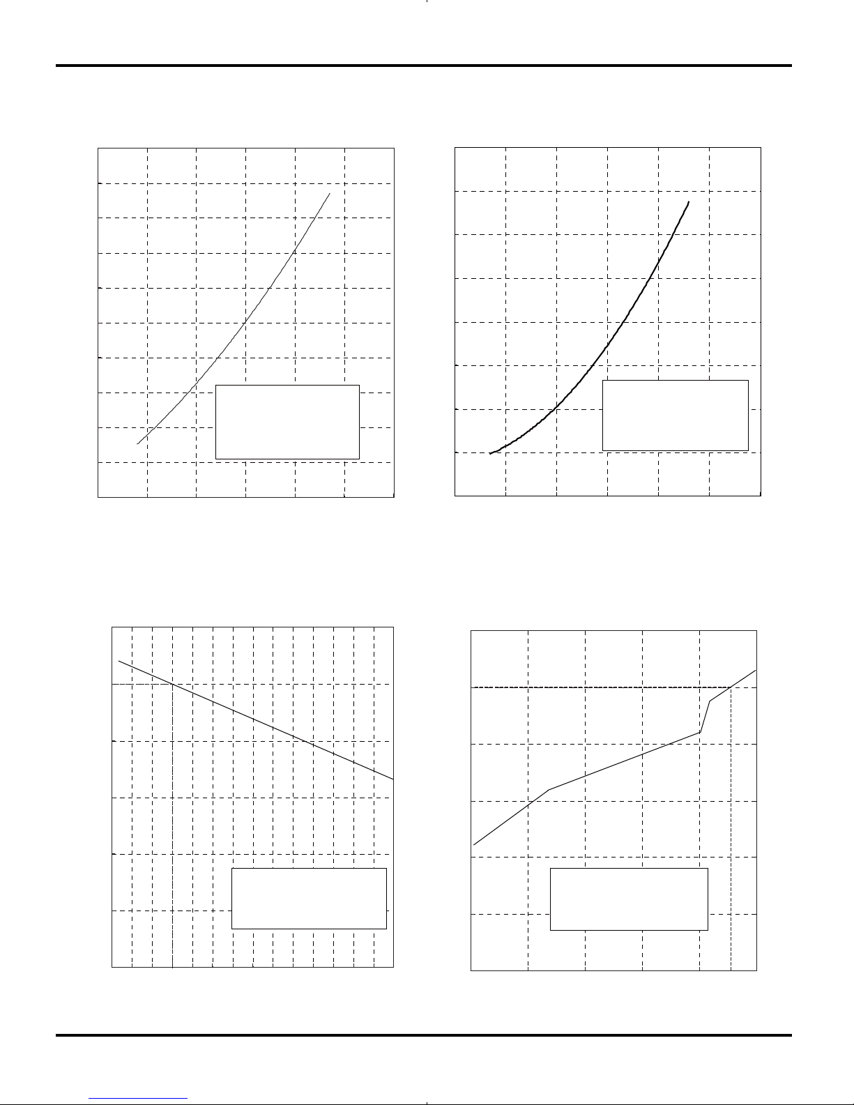
2.2 Operation Characteristic Curve
0
1
2
3
4
5
6
7
8
9
10
0 20 40 60 80 100 120
Condition
Indoor:DB 27ć WB19ć
Indoor air flow: Super High
Pipe length:5m
Voltage:230V
Compressor Speed(rps)
0
1
2
3
4
5
6
7
8
0 20 40 60 80 100 120
Condition
Indoor:DB 20ć
Indoor air flow: Super High
Pipe length:5m
Voltage:230V
Compressor Speed(rps)
Cooling
Heating
Current(A)
Current(A)
2.3 Capacity Variation Ratio According to Temperature
50
60
70
80
90
100
110
32 33 34 35 36 37 38 39 40 41 42 43 44 45 46
Capacity ratio(%)
Condition
Indoor:DB27℃ WB19℃
Indoor air flow: Super High
Pipe length:5m
Outdoor temp. (°C)
0
20
40
60
80
100
120
-15 -10 -5 0 5 10
Capacity ratio(%)
Condition
Indoor:DB20℃
Indoor air flow: Super High
Pipe length:5m
Outdoor temp. (°C)
Cooling Heating
Specifications
12
Cooling
Heating
NOTES :
(1) Measure surface temperature of heat exchanger pipe around center of heat exchanger path U
bent. (Thermistor themometer)
(2) Connecting piping condition : 5 m
2.4 Operation Date
Indoor Outdoor
09K 0.9 to 1.1 53
12K 0.8 to 1.0 72
Outdoor
Fan Mode
Compressor
Revolution(rps)
27/19 35/24 Super High 930rpm
Temp. Condition(℃)
Mode l
Standard
Pressure(Mpa)
Indoor Fan
Mode
Indoor Outdoor
09K 2 .3 to 2.5 72
12K 2 .4 to 2.6 78
Outdoor
Fan Mode
Compress or
Revolution(rps)
20/- 7/6 Super High 930rpm
Temp. Condition(℃)
Model
Standard
Pressure(Mpa)
Indoor Fan
Mode
Specifications
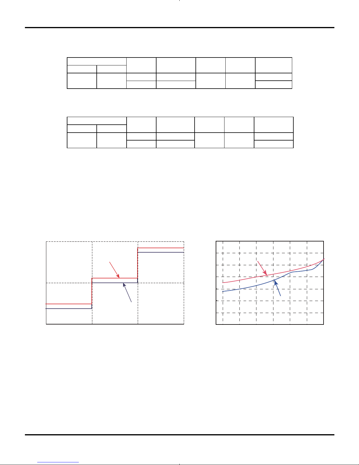
2.5 Noise Criteria Curve Tables for Both Models
40
30
20
Indoor side noise when blowing
Indoor fan motor rotating speed
Low Middle High
12K
09K
40
42
44
46
48
50
52
54
20 4030 50 60 70 80
Compressor frequency(Hz)
Noise dB(A)
Noise dB(A)
Heating
Cooling
13
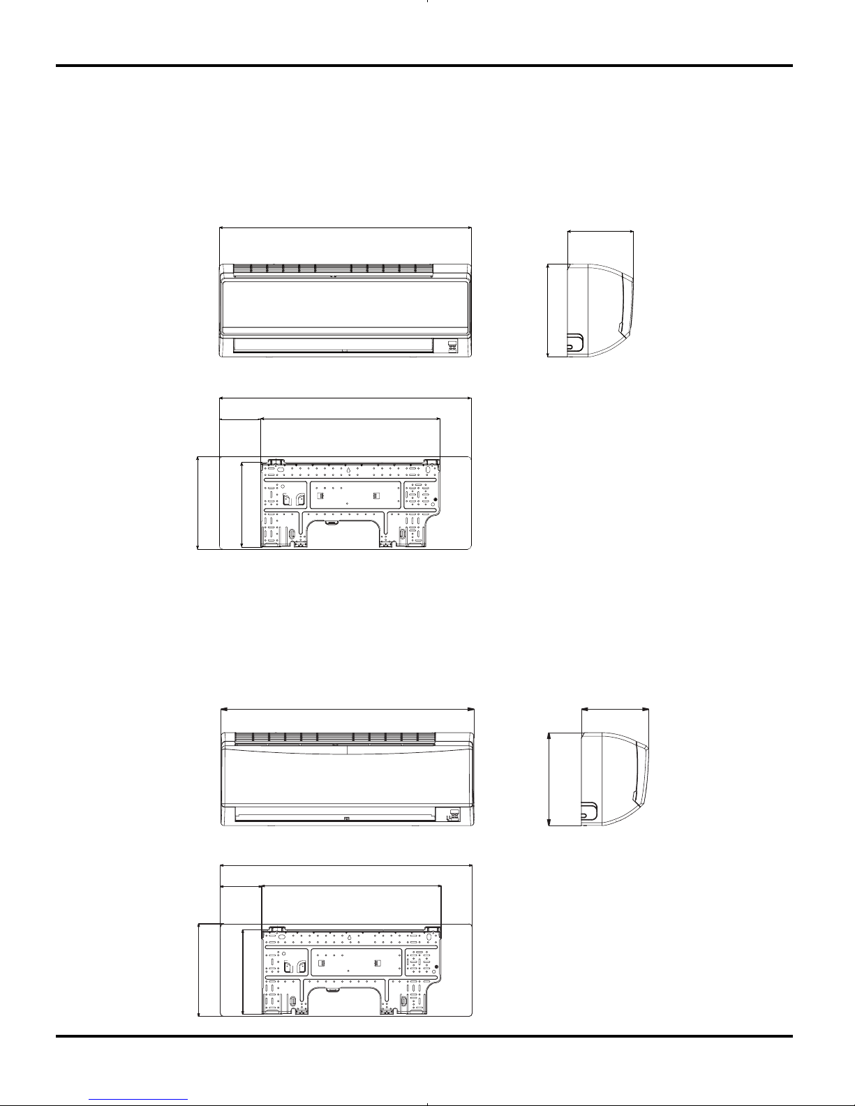
3. Construction Views
3.1 Indoor Unit
Constrction views
Models:GWC09KF-K3DNA5A/I,GWH09KF-K3DNA5A/I,GWC12KF-K3DNA5A/I,GWH12KF-K3DNA5A/I
Models:GWH09KF-K3DNA6A/I,GWH12KF-K3DNA6A/I
548.5
258.5
126.5
770
283
770
283
201
770
201
283
548.5
258.5
126.5
770
283
Unit:mm
14
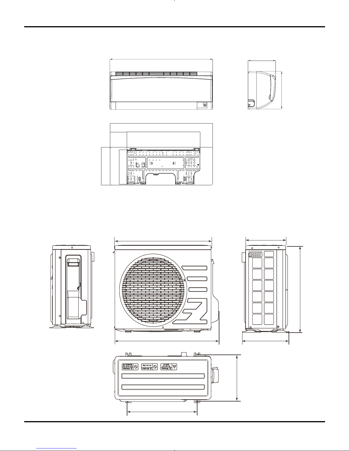
3.2 Outdoor Unit
Constrction views
710
658
275
550
318
470
299
Models:GWH09KF-K3DNB1A/I,GWH12KF-K3DNB1A/I
548.5
258.5
126.5
770
283
283
201
770
15
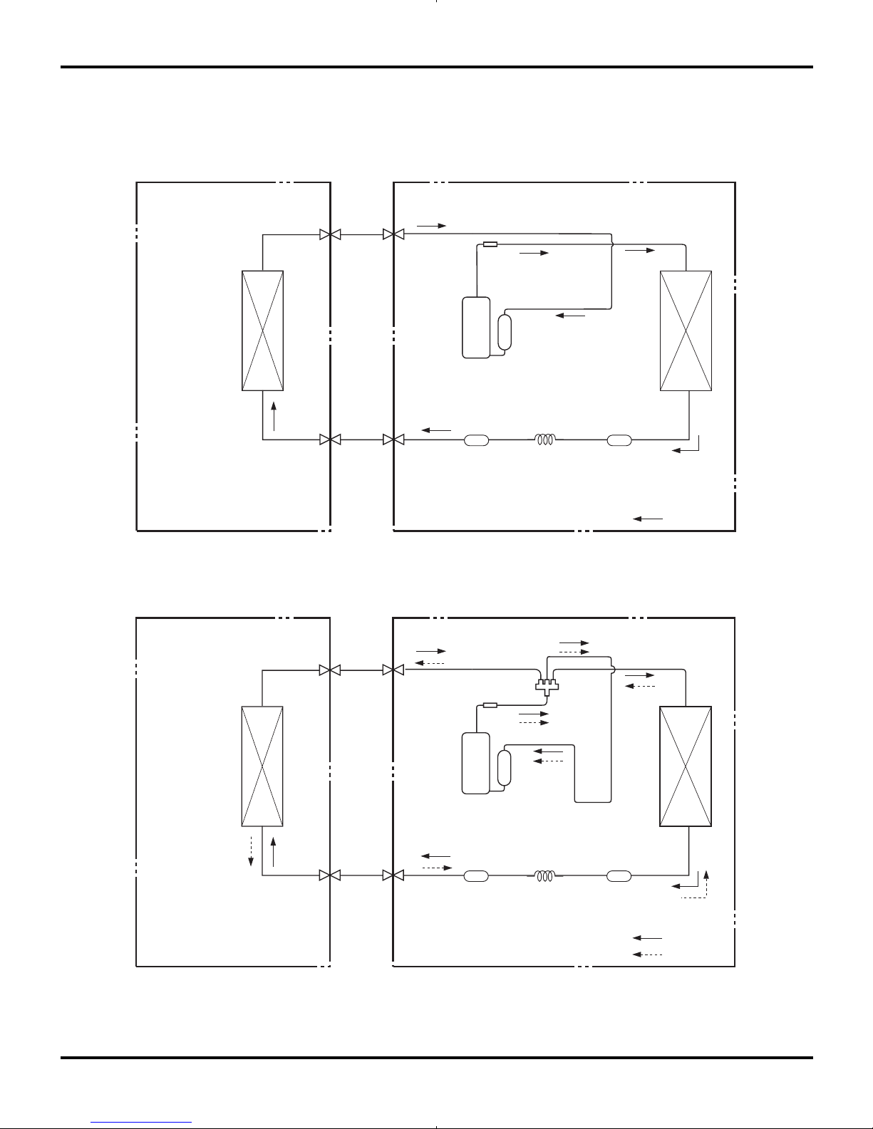
4. Refrigerant System Diagram
INDOOR UNIT OUTDOOR UNIT
HEAT
EXCHANGE
(EVAPORATOR)
HEAT
EXCHANGE
(CONDENSER)
COMPRESSOR
GAS SIDE
3-WAY VALVE
LIQUID SIDE
3-WAY VALVE
COOLING
HEATING
Accumlator
Discharge
Suction
Muffler
4-Way valve
CapillaryStrainer Strainer
Refrigerant pipe diameter
Liquid : 1/4" (6 mm)
Gas : 3/8" (9.52 mm)
INDOOR UNIT OUTDOOR UNIT
HEAT
EXCHANGE
(EVAPORATOR)
HEAT
EXCHANGE
(CONDENSER)
COMPRESSOR
GAS SIDE
3-WAY VALVE
LIQUID SIDE
2-WAY VALVE
COOLING
Accumlator
Discharge
Suction
Muffler
CapillaryStrainer Strainer
(1)Cooling Only Models
(2)Cooling & Heating Models
Refrigerant System Diagram
16
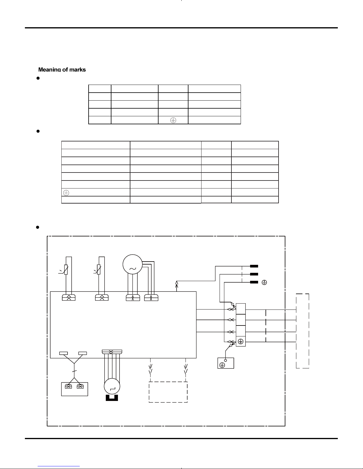
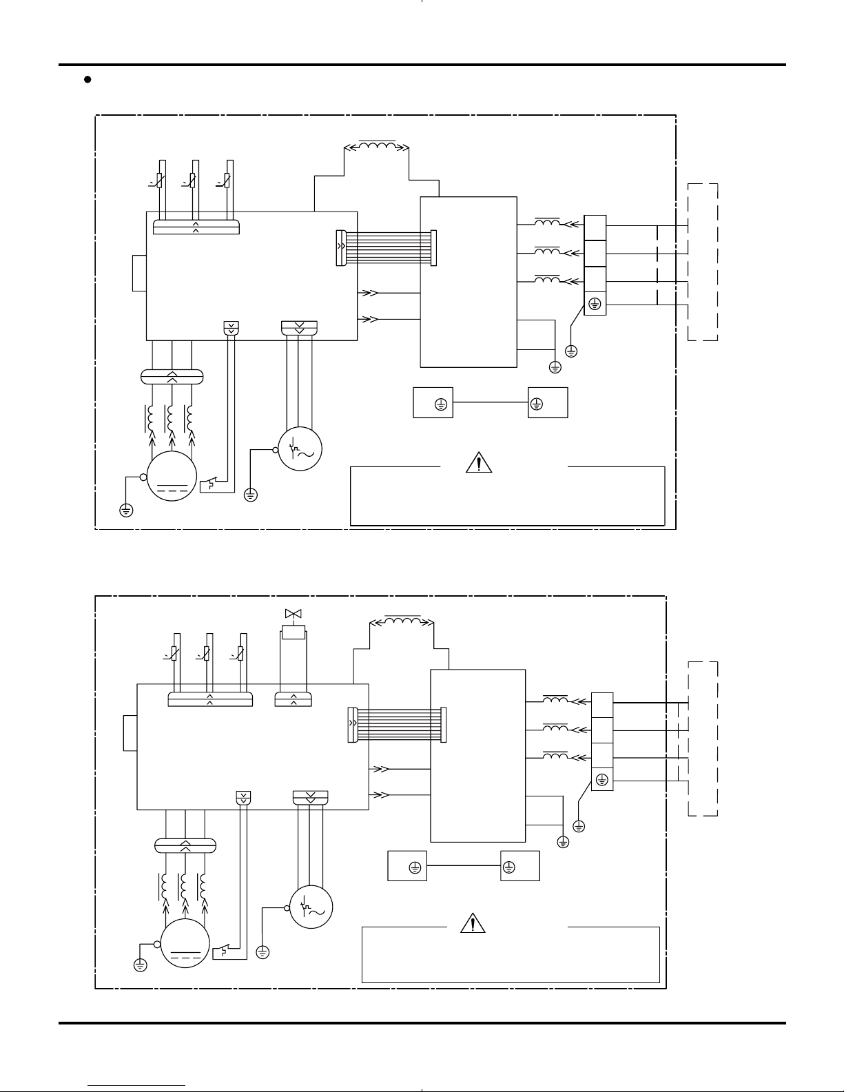
5. Schematic Diagram
5.1 Electrical Data
5.2 Electrical wiring
Outdoor Unit
Symbol Color symbol Symbol Color symbol
WH
WHITE
BN
BROWN
YE
YELLOW
BU
BLUE
RD
RED
BK
BLACK
YEGN
YELLOW GREEN PROTECTIVE EARTH
Indoor Unit
Indoor Unit
Schematic Diagram
Symbol Parts name Symbol Color symbol
L1
REACTOR
WH
WHITE
PCB1~PCB2
PRINTED CIRCUIT BOARD
YE
YELLOW
S10/S11S40/S70/S80/S90
CONNECTOR
RD
RED
SAT
OVERLOAD
BN
BROWN
COMP
COMPRESSOR
BU
BLUE
PROTECTIVE EARTH
BK
BLACK
YEGN
YELLOW GREEN
ORANGE
OG
to the models with cold-plasma function.
NOTE:The part with broken line is applicable
GENERATOR
COOL PLASMA
HEALTH-L HEALTH-N
AP2
MOTOR
SWING
DISPLAY
OUTDOOR UNIT
TUBE
TEM.SENSOR
ROOM
TEM.SENSOR
FAN
MOTOR
PG
RD
BU
M1
PGF
SWING-UD
DISP2
L-OUT
AC-L
AP1
BU
BN
BK
COM-OUT
YEGN
PE
BN
BK
RT2
0
DISP1
RT1
2
YEGN
3
YEGN
N
BU
BU
XT
N(1)
L
BN
POWER
M2
N
ROOM
TUBE
0
EVAPORATOR
17
W
V
U
MOTOR
YEGN
X1
4YV
PE PE
PE
S40
PE
SAT
HA2
HA1
COMP.
S70
HR1
HR2
L1
HL3
HN3
HN2
HL2
S10 S11
S80S90
0
RT5
RT4
0
RT3
0
W
V
U
PCB2
E2
E1
AC1
S
AC2
PCB1
PE
2
3
XT
N(1)
WARNING
Please don't touch any terminal when the voltage of
prevent the risk of electrical shock!
terminal DC+ and DC- at PCB2 is higher than 30V to
INDOOR UNIT
M
YEGN
CLAPBOARD
SUB-ASSY
ELECTRICAL BOX
TEM.SENSOR
OUTTUBE OUTROOM
TEM.SENSOR
TEM.SENSOR
EXHAUST
OG
YEGN
YEGN
BURD YE
WH
YEGN
BU
BN
BU
BU
BK
BN
YEGN
WH
RD BU
OG
YE
FAN
YEGN
BU
BN
BK
Outdoor Unit
Models GWC09KF-K3DNA5A/O ,GWC12KF-K3DNA5A/O
N(1)
XT
3
2
PE
PCB1
AC2
S
AC1
E1
E2
PCB2
U
V
W
0
RT3
0
RT4
RT5
0
S90
S11S10
HL2
HN2
HN3
HL3
L1
HR2
HR1
FAN
S70
COMP.
HA1
HA2
SAT
PE
S40
PE
PEPE
X1
YEGN
MOTOR
U
V
W
BK
BN
BU
YEGN
YE
OG
CLAPBOARD
BURD
WH
YEGN
BN
BK
BU
BU
BN
BU
YEGN
WH
YERD BU
YEGN
YEGN
OG
EXHAUST
TEM.SENSOR
TEM.SENSOR
OUTROOMOUTTUBE
TEM.SENSOR
ELECTRICAL BOX
SUB-ASSY
YEGN
M
INDOOR UNIT
WARNING
Please don't touch any terminal when the voltage of
prevent the risk of electrical shock!
terminal DC+ and DC- at PCB2 is higher than 30V to
Models GWH09KF-K3DNA5A/O ,GWH12KF-K3DNA5A/O ,GWH09KF-K3DNA6A/O ,
GWH12KF-K3DNA6A/O , GWH09KF-K3DNB1A/O ,GWH12KF-K3DNB1A/O
Schematic Diagram
These circuit diagrams are subject to change without notice, please refer to the one supplied with the unit.
18
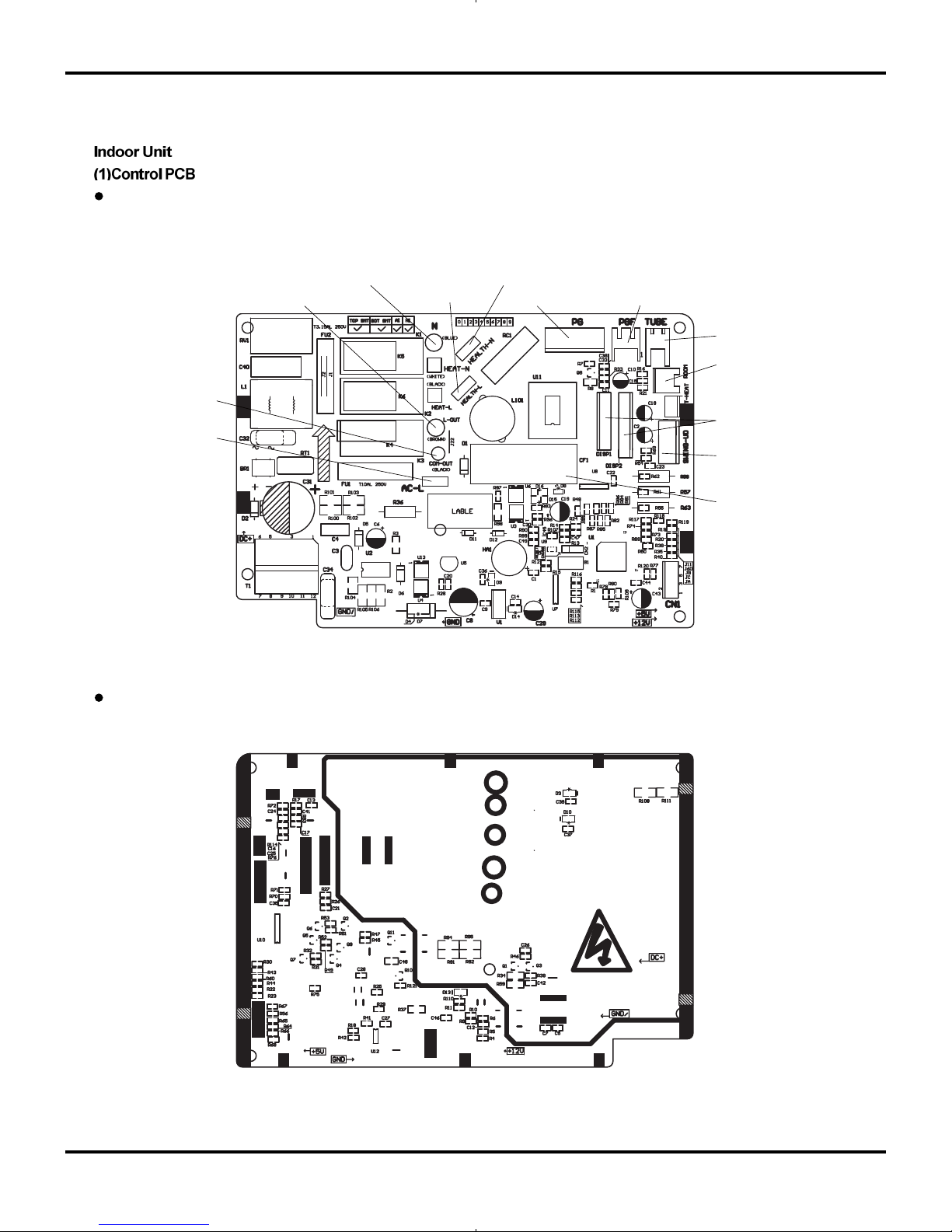
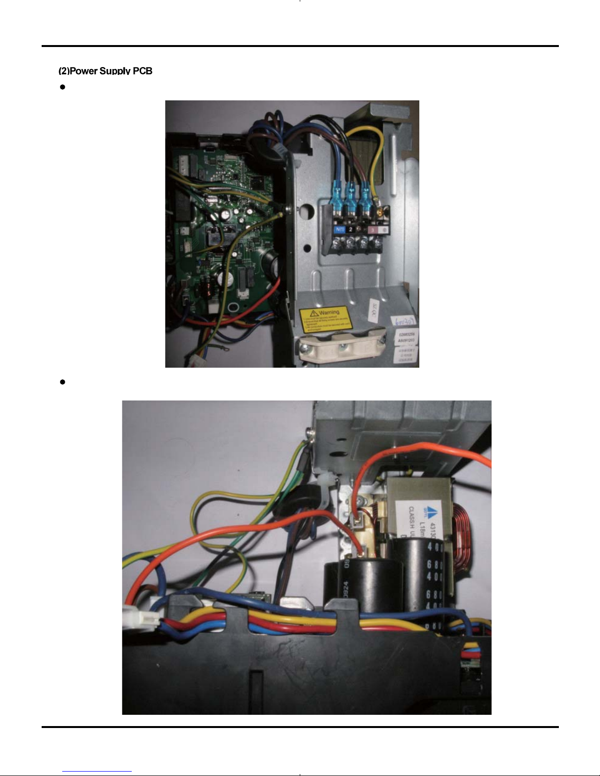
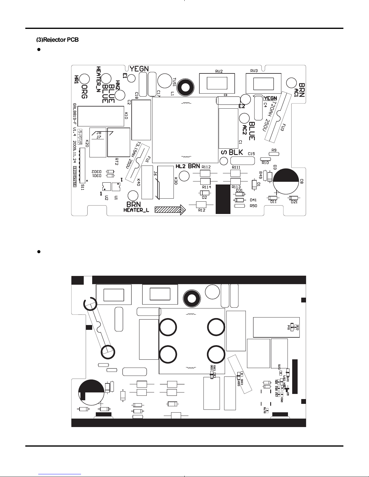
5.3 Printed Circuit Board
TOP VIEW
BOTTOM VIEW
Schematic Diagram
Interface of input live wire
Interface of input null wire
Interface of live wire
of cold-plasma
Interface of null wire of cold-plasma
Interface of indoor fan
Interface for feedback of indoor fan
Interface of pipe temp sensor
Interface of ambient temp sensor
Interface of communication wire
Interface of input live wire
Interface of motor
Interface of capacitor of fan
Interface of display device
19
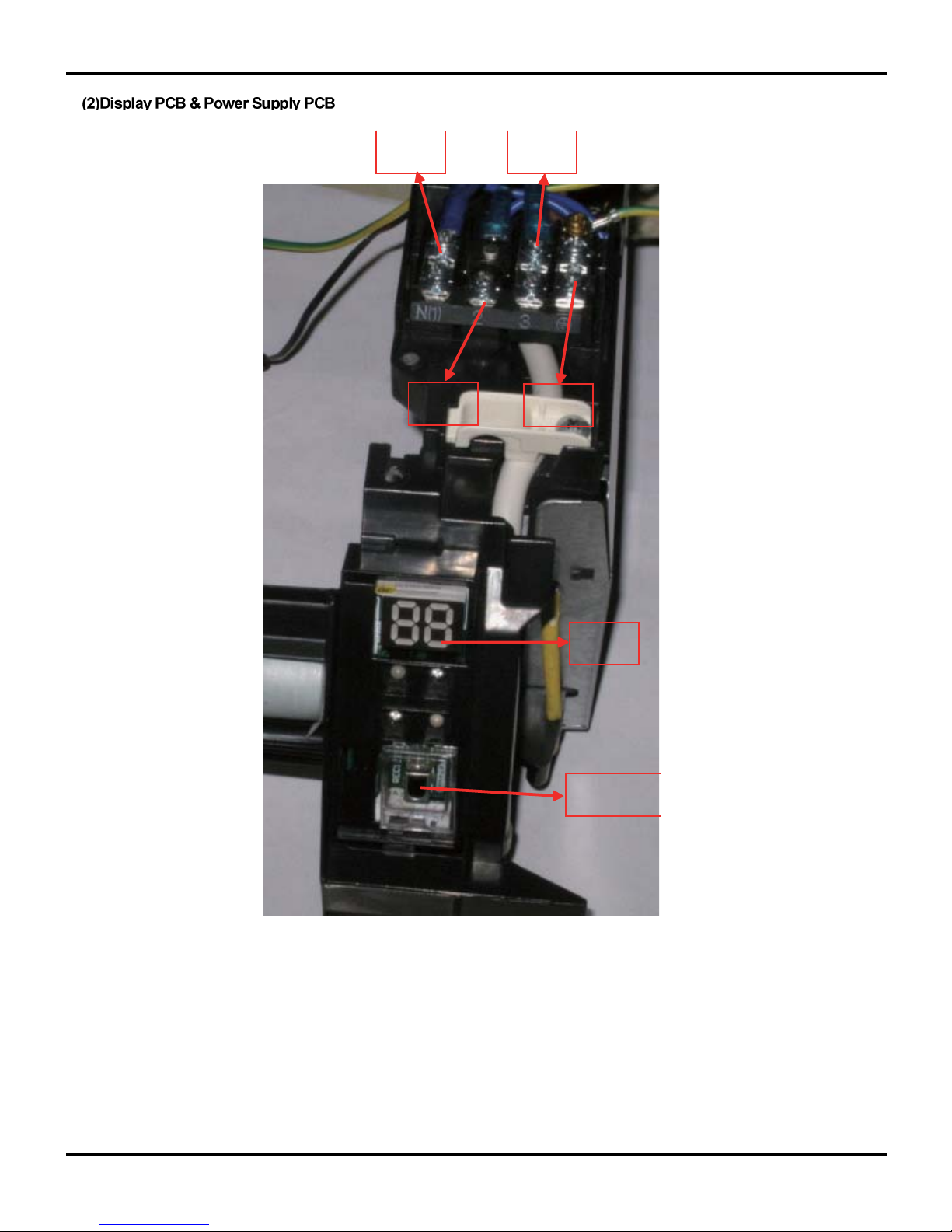
Schematic Diagram
null line live wire
communication
wire
ground wire
dispaly
board
infrared
receiver
20
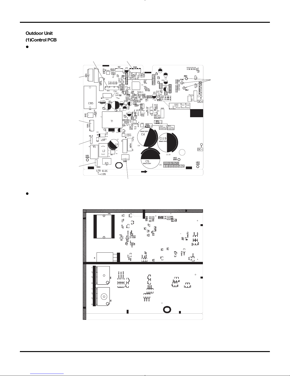
TOP VIEW
BOTTOM VIEW
Schematic Diagram
Interface of mainboard and wave filter
Interface of temp sensor
Interface of compressor
Interface of outdoor fan
Interface of overload protector of compressor
Interface of live wire
Interface of null wire
Interface of 4-way valve
21
FRONT VIEW
BOTTOM VIEW
Schematic Diagram
22
TOP VIEW
Schematic Diagram
BOTTOM VIEW
23
6. Function and Control
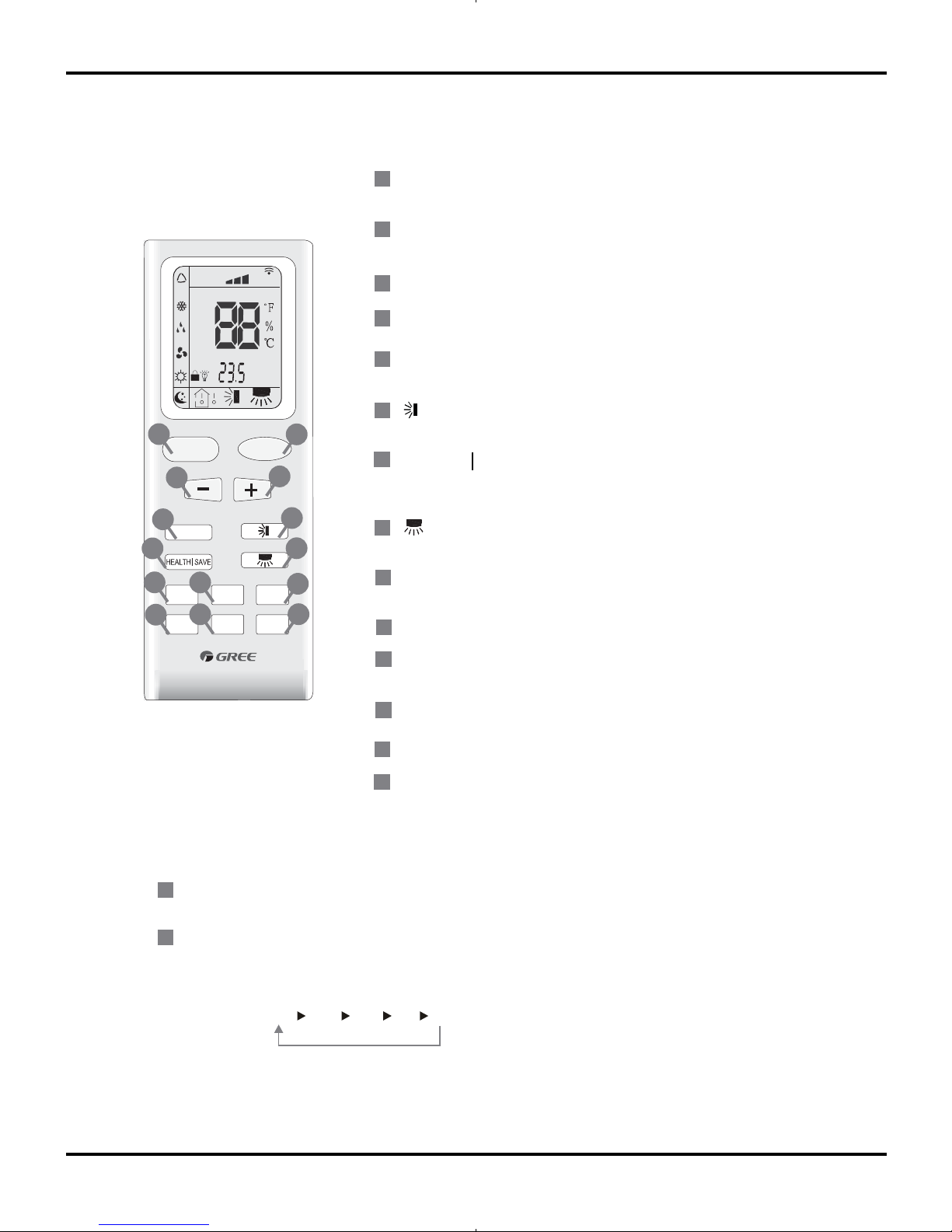
6.1 Remote Control Operations
Function and Control
Press this button to start or stop operation.
ON/OFF
MODE
+
-
Press it to select operation mode
(AUTO/COOL/DRY/FAN/HEAT).
: Press it to increase temperature setting.
: Press it to decrease temperature setting.
FA
HEALTH SAVE
N
Press it to set up &down swing angle.
TIMER
X-FAN
(X-FAN is the alternative expression of BLOW for the
purpose of understanding.)
Press it to select health mode on or off.
TEMP
TURBO
SLEEP
LIGHT
Press it to set fan speed.
Press it set auto-on timer/auto-off timer.
1
2
7
4
3
5
6
Press it to set left & right swing angle.
8
11
9
10
12
13
14
FAN
AUTO
OPER
HEALTH
AIR
FILTER
TURBO
ON/OFF
X-FAN
HOUR
HUMIDITY
ON/OFF
MODE
FAN
X-FAN
TURBO
TEMP
TIMER
SLEEP
LIGHT
2
11
7
10
13
9
43
12
8
6
14
5
1
Press it to turn on/off the light.
Remote controller description
ON/OFF :
MODE :
1
2
Press this button to start the unit operation .Press this button again to stop the unit operation.
Each time you press this button,a mode is selected in a sequence that goes from AUTO, COOL,DRY, FAN,
and HEAT
*,
as the following:
AUTO
COOL
DRY
FAN HEAT
*
*Note:Only for models with heating
function.
After energization, AUTO mode is defaulted. In AUTO mode, the set temperature will not be displayed on the
mode in accordance with the room temp
erature to make indoor room comfortable.
LCD, and the unit will automatically select the suitable operation
24
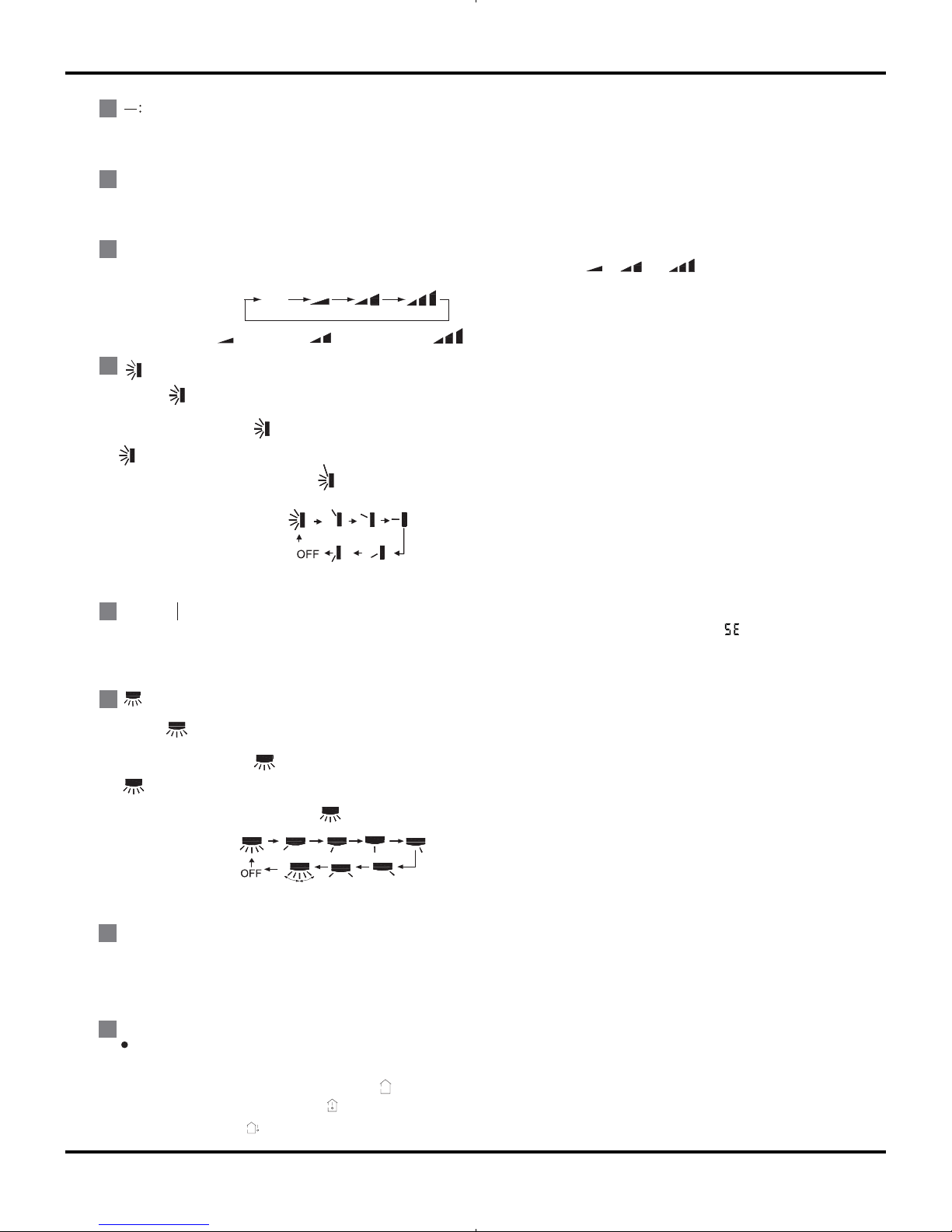
Function and Control
+
:
FAN :
4
3
5
Press this button to decrease set temperature.Holding it down above 2 seconds rapidly.decreases set temperature. In
Press this button to increase set temperature.Holding it down above 2 seconds rapidly increases set temperature. In
This button is used for setting fan speed in the sequence that goes from AUTO,
,
to
then back to Auto.
,
,
Aut o
Low speed
Medium speed
High speed
:
6
Press button to start or stop up & down swing function.The remote controller
defaults to simple swing condition.
Press + button and button at the same time at unit OFF to switch bet
ween simple swing and static swing,
blinking 2 seconds.
In static swing condition, press
If the unit is turned off during swing operation,the louver will stop at present position.
button, the swing angle of up & down louver changes as below:
●
●
●
●
AUTO mode, set temperature is not adjustable.
AUTO mode, set temperature is not adjustable.
HEALTH SAVE:
Press HEALTH part of this button to turn on or off HEALTH function.
7
X-FAN:
9
10
TEMP:
:
8
Pressing X-FAN button in COOL or DRY mode,the icon "X-FAN" is displayed and the indoor fan will continue operation
for 10 minutes in order to dry the indoor unit even though you have turned off the unit.
After energization, X-FAN OFF is defaulted. X-FAN is not available in AUTO,FAN or HEAT mode.
Pressing SAVE part of this button,
and the unit goes into SAVE operation mode. Press SAVE part of the button again to cancel SAVE function .During
SAVE operation, the tmperature and fan speed is not adjustable.
is displayed
Press + button and button at the same time at unit OFF to switch between simple swing and static swing,
Press button to start or stop left & right swing function.The remote controller defaults to simple swing condition.
blinking 2 seconds..
In static swing condition, press button, the swing angle of left & right louver
changes as below:
●
●
●
If the unit is turned off during swing operation,the louver will stop at present position.
●
Press this button to select set temperature or indoor ambient temp to be displayed by indoor unit. When there is no mark displayed
on remote controller, the current display will not change after the signal is received by indoor unit ( set temperature will be shown
when first energization of the unit); When “ ” is displayed on remote control, the set temp will be displayed after the signal
is received by indoor unit; When “ ” is displayed,the indoor ambient temp will be displayed after the signal is received by
indoor unit; When “ ” is displayed on remote control, the current display will not change after the signal is received by indoor
unit.
 Loading...