

Gree GWH12KF-K3DNA6G, GWH12KF-K3DNA9G, GWH09KF-K3DNA6G, GWH09KF-K3DNA9G, GWH12KF-K3DNB2G Service Manual
...
GREE ELECTRIC APPLIANCES,INC.OF ZHUHAI
Change for Life
Service Manual
Models: GWH09KF-K3DNA5G
GWH09KF-K3DNA6G
GWH09KF-K3DNA9G
GWH09KF-K3DNB2G
GWH12KF-K3DNA5G
GWH12KF-K3DNA6G
GWH12KF-K3DNA9G
GWH12KF-K3DNB2G
GWH12KF-K3DNB3G
(Refrigerant R410A)

Service Manual
Table of Contents
Table of Contents
Part
Ⅰ
: Technical Information
.......................................................................1
1. Summary
......................................................................................................................1
2. Specications
..........................................................................................................2
2.1 Specication Sheet ...........................................................................................................2
2.2 Operation Characteristic Curve ........................................................................................6
2.3 Capacity Variation Ratio According to Temperature .........................................................6
2.4 Cooling and Heating Data Sheet in Rated Frequency .....................................................7
2.5 Noise Curve ......................................................................................................................7
3. Outline Dimension Diagram
........................................................................8
3.1 Indoor Unit ........................................................................................................................8
3.2 Outdoor Unit .....................................................................................................................8
4. Refrigerant System Diagram
......................................................................9
5. Electrical Part
.........................................................................................................10
5.1 Wiring Diagram ...............................................................................................................10
5.2 PCB Printed Diagram .....................................................................................................12
6. Function and Control
......................................................................................14
6.1 Remote Controller Introduction .....................................................................................14
6.2 Brief Description of Modes and Functions ......................................................................18
Part
Ⅱ
: Installation and Maintenance
.................................................22
7. Notes for Installation and Maintenance
..........................................22
8. Installation
................................................................................................................24
8.1 Installation Dimension Diagram ......................................................................................24
8.2 Installation Parts-checking ............................................................................................26
8.3 Selection of Installation Location ....................................................................................26
8.4 Electric Connection Requirement ...................................................................................26
8.5 Installation of Indoor Unit ................................................................................................26
8.6 Installation of Outdoor Unit .............................................................................................29
8.7 Vacuum Pumping and Leak Detection ...........................................................................30
8.8 Check after Installation and Test Operation ...................................................................30

Service Manual
9. Maintenance
............................................................................................................31
9.1 Flashing LED of Indoor/Outdoor Unit and Primary Judgement ......................................31
9.2 Procedure of Troubleshooting ........................................................................................39
9.3 Maintenance Method for Normal Malfunction .................................................................54
10. Exploded View and Parts List
..............................................................56
10.1 Indoor Unit ....................................................................................................................56
10.2 Outdoor Unit .................................................................................................................62
11. Removal Procedure
.......................................................................................65
11.1 Removal Procedure of Indoor Unit ...............................................................................65
11.2 Removal Procedure of Outdoor Unit ............................................................................79
Appendix:
........................................................................................................................84
Appendix 1: Reference Sheet of Celsius and Fahrenheit ....................................................84
Appendix 2: Conguration of Connection Pipe .....................................................................84
Appendix 3: Pipe Expanding Method ...................................................................................85
Appendix 4: List of Resistance for Temperature Sensor ......................................................86
1
Technical Information
Service Manual
1. Summary
Part
Ⅰ
: Technical Information
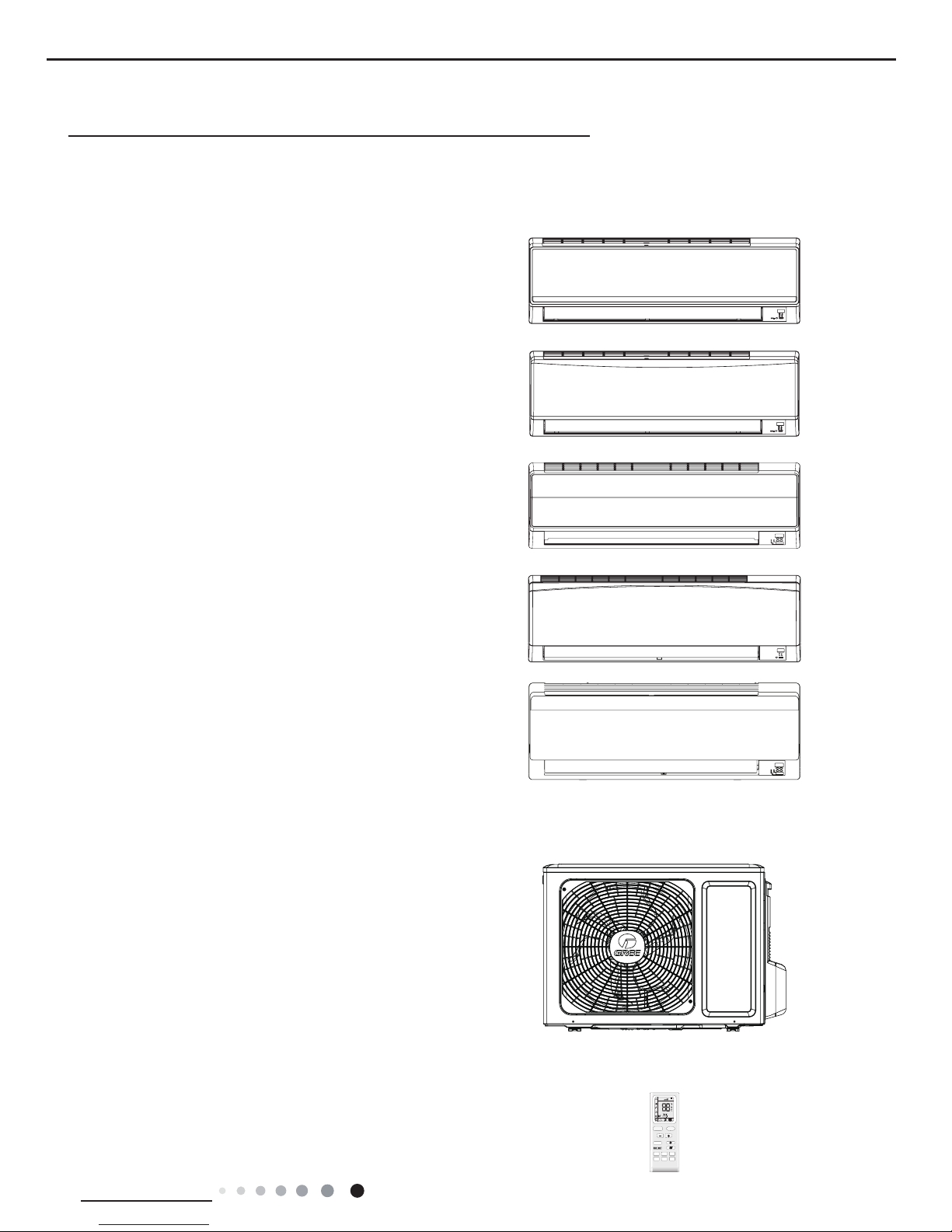
Indoor Unit:
GWH09KF-K3DNA6G/I(Cold Plasma)
GWH12KF-K3DNA6G/I(Cold Plasma)
GWH09KF-K3DNA5G/I(Cold Plasma)
GWH12KF-K3DNA5G/I(Cold Plasma)
GWH09KF-K3DNB2G/I(Cold Plasma)
GWH12KF-K3DNB2G/I(Cold Plasma)
GWH09KF-K3DNA9G/I
GWH12KF-K3DNA9G/I
GWH12KF-K3DNB3G/I(Cold Plasma)
Outdoor Unit:
Remote Controller
:
GWH09KF-K3DNA6G/O
GWH12KF-K3DNA6G/O
YB1F2(XFAN)
FAN
AUTO
OPER
HEALTH
AIR
FILTER
TURBO
ON/OFF
X-FAN
HOUR
HUMIDITY
ON/OFF
MODE
FAN
X-FAN
TURBO
TEMP
TIMER
SLEEP
LIGHT
ON/OFF
2
Technical Information
Service Manual
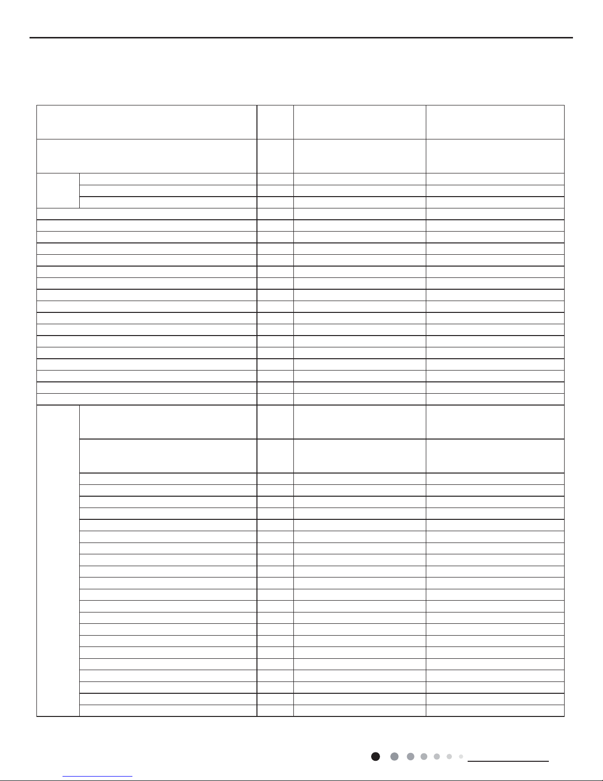
2. Specications
2.1 Specication Sheet
Model
GWH09KF-K3DNA6G(LCLH)
GWH09KF-K3DNB2G(LCLH)
GWH09KF-K3DNA5G(LCLH)
GWH12KF-K3DNA6G(LCLH)
GWH12KF-K3DNB2G(LCLH)
GWH12KF-K3DNA5G(LCLH)
Product Code
CB146036201
CB409002701
CB146037601
CB146036101
CB409002401
CB146037501
Power
Supply
Rated Voltage V~ 220-240 220-240
Rated Frequency Hz 50 50
Phases 1 1
Power Supply Mode Outdoor Outdoor
Cooling Capacity(Min~Max) W 2600(450~3230) 3500(450~3230)
Heating Capacity(Min~Max) W 2800(450~4100) 3800(450~4100)
Cooling Power Input(Min~Max) W 870(200~1420) 1150(200~1420)
Heating Power Input(Min~Max) W 900(200~1550) 1100(200~1550)
Cooling Current Input A 3.8 5.1
Heating Current Input A 4.0 4.9
Rated Input W 1550 1650
Rated Cooling Current A 6.3 6.9
Rated Heating Current A 6.9 7.3
Air Flow Volume (SH/H/M/L) m
3
/h 600/520/370/280 680/560/410/300
Dehumidifying Volume L/h 0.8 1.4
EER W/W 2.99 3.04
COP W/W 3.11 3.45
SEER 5.6 5.6
SCOP / /
Application Area m
2
12-18 16-24
Indoor
Unit
Indoor Unit Model
GWH09KF-K3DNA6G/I
GWH09KF-K3DNB2G/I
GWH09KF-K3DNA5G/I
GWH12KF-K3DNA6G/I
GWH12KF-K3DNB2G/I
GWH12KF-K3DNA5G/I
CB146N36200
CB409N02701
CB146N37600
CB146N36100
CB409N02400
CB146N37500
Indoor Unit Fan Type Cross-ow Cross-ow
Indoor Unit Fan Diameter Length(DXL) mm Ф92X596 Ф92X596
Cooling Speed (SH/H/M/L) r/min 1350/1100/900/700 1350/1150/950/750
Heating Speed (SH/H/M/L) r/min 1350/1140/980/820 1350/1190/1020/850
Indoor Unit Fan Motor Power Output W 10 10
Indoor Unit Fan Motor RLA A 0.18 0.18
Indoor Unit Fan Motor Capacitor μF 1.2 1.2
Evaporator Form Aluminum Fin-copper Tube Aluminum Fin-copper Tube
Evaporator Pipe Diameter mm Ф7 Ф7
Evaporator Row-n Gap mm 2-1.4 2-1.4
Evaporator Coil Length (LXDXW) mm 610X24X294 610X24X294
Swing Motor Model MP24BA MP24BA
Swing Motor Power Output W 1.5 1.5
Fuse Current A 3.15 3.15
Indoor Unit Sound Pressure Level (SH/H/M/L) dB (A) 41/38/30/24 42/39/31/25
Indoor Unit Sound Power Level (SH/H/M/L) dB (A) 55/52/44/38 56/53/45/39
Indoor Unit Dimension (WXHXD) mm 770X283X201 770X283X201
Indoor Unit Dimension of Carton Box (LXWXH) mm 844X342X261 844X342X261
Indoor Unit Dimension of Package (LXWXH) mm 847X345X276 847X345X276
Indoor Unit Net Weight kg 8 9
Indoor Unit Gross Weight kg 9.5 10.5
3
Technical Information
Service Manual
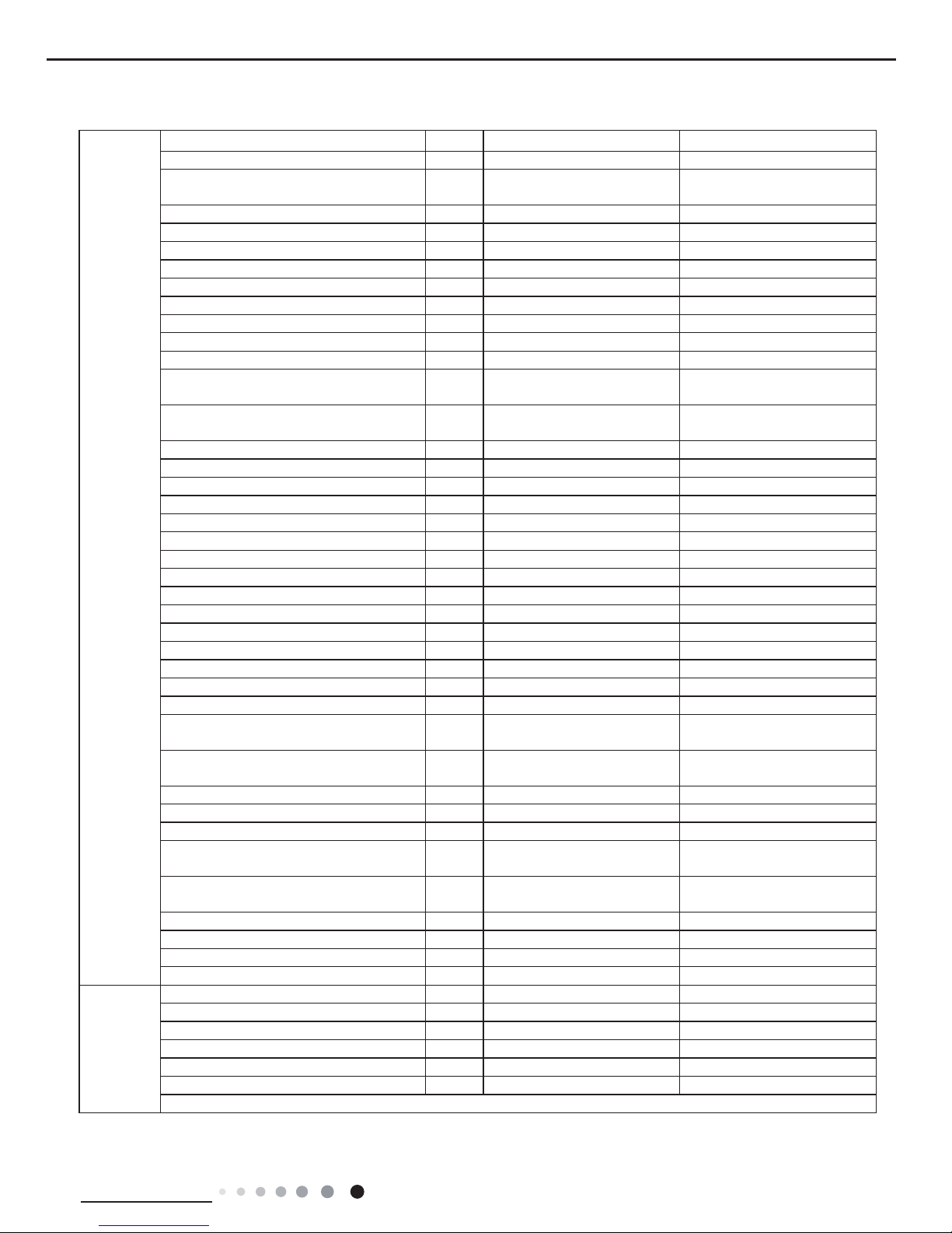
The above data is subject to change without notice; please refer to the nameplate of the unit.
Outdoor Unit
Outdoor Unit Model GWH09KF-K3DNA6G/O GWH12KF-K3DNA6G/O
Outdoor Unit Product Code CB146W36201 CB146W36101
Compressor Manufacturer
ZHUHAI LANDA
COMPRESSOR CO.,LTD.
ZHUHAI LANDA
COMPRESSOR CO.,LTD.
Compressor Model QXA-A091zE190A QXA-A091zE190A
Compressor Oil RB68EP RB68EP
Compressor Type Rotary Rotary
Compressor Locked Rotor Amp (L.R.A) A 20 20
Compressor Rated Load Amp (RLA) A 4.5 4.5
Compressor Power Input W 942 942
Compressor Overload Protector 1NT11L-6233 1NT11L-6233
Throttling Method Electron expansion valve Electron expansion valve
Set Temperature Range °C 16~30 16~30
Cooling Operation Ambient Temperature
Range
°C -15~43 -15~43
Heating Operation Ambient Temperature
Range
°C -20~24 -20~24
Condenser Form Aluminum Fin-copper Tube Aluminum Fin-copper Tube
Condenser Pipe Diameter mm Ф7 Ф7
Condenser Rows-n Gap mm 1-1.4 2-1.4
Condenser Coil Length (LXDXW) mm 710X19.05X508 710X38.1X506
Outdoor Unit Fan Motor Speed rpm 900 900
Outdoor Unit Fan Motor Power Output W 30 30
Outdoor Unit Fan Motor RLA A 0.36 0.36
Outdoor Unit Fan Motor Capacitor μF / /
Outdoor Unit Air Flow Volume m
3
/h 1600 1600
Outdoor Unit Fan Type Axial-ow Axial-ow
Outdoor Unit Fan Diameter mm Ф400 Ф400
Defrosting Method Automatic Defrosting Automatic Defrosting
Climate Type T1 T1
Isolation I I
Moisture Protection IP24 IP24
Permissible Excessive Operating Pressure
for the Discharge Side
MPa 4.3 4.3
Permissible Excessive Operating Pressure
for the Suction Side
MPa 2.5 2.5
Outdoor Unit Sound Pressure Level (H/M/L) dB (A) 51/-/- 53/-/Outdoor Unit Sound Power Level (H/M/L) dB (A) 62/-/- 63/-/Outdoor Unit Dimension (WXHXD) mm 776X540X320 776X540X320
Outdoor Unit Dimension of Carton Box
(LXWXH)
mm 848X360X580 848X360X580
Outdoor Unit Dimension of Package
(LXWXH)
mm 851X363X595 851X363X595
Outdoor Unit Net Weight kg 28 29
Outdoor Unit Gross Weight kg 31 32
Refrigerant R410A R410A
Refrigerant Charge kg 0.7 0.85
Connection
Pipe
Connection Pipe Length m 5
5
Connection Pipe Gas Additional Charge g/m 20
20
Outer Diameter of Liquid Pipe mm Ф6
Ф6
Outer Diameter of Gas Pipe mm Ф9.52
Ф9.52
Max Distance Height m 10
10
Max Distance Length m 15
20
Note: The connection pipe applies metric diameter.
4
Technical Information
Service Manual
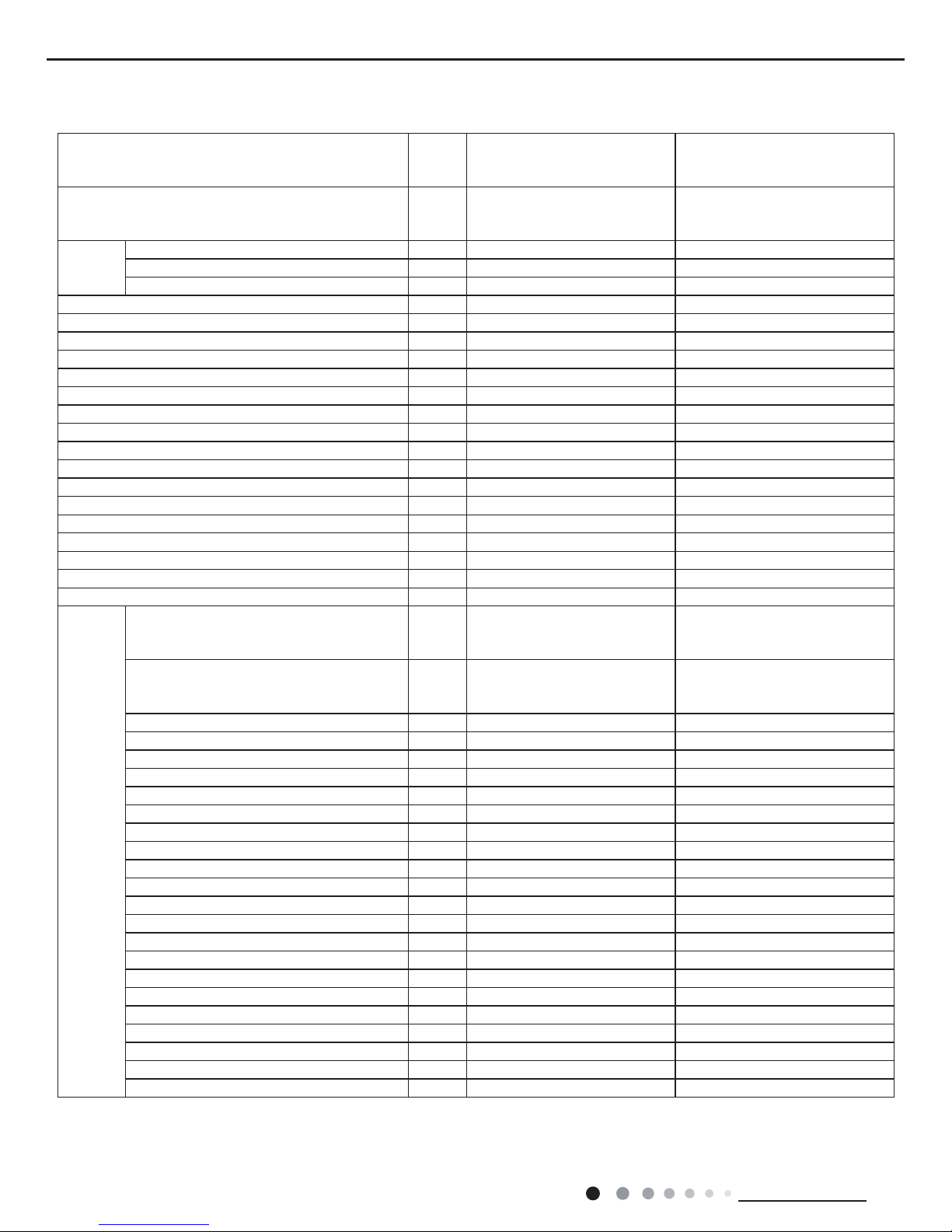
Model
GWH09KF-K3DNA6G(LC)
GWH09KF-K3DNA9G(LC)
GWH12KF-K3DNA6G(LC)
GWH12KF-K3DNA9G(LC)
GWH12KF-K3DNB3G(LC)
Product Code
CB146036200
CB146037000
CB146036100
CB146037100
CB146037800
Power
Supply
Rated Voltage V~ 220-240 220-240
Rated Frequency Hz 50 50
Phases 1 1
Power Supply Mode Outdoor Outdoor
Cooling Capacity(Min~Max) W 2600(450~3230) 3500(450~3230)
Heating Capacity(Min~Max) W 2800(450~4100) 3800(450~4100)
Cooling Power Input(Min~Max) W 870(200~1420) 1150(200~1420)
Heating Power Input(Min~Max) W 900(200~1550) 1100(200~1550)
Cooling Current Input A 3.8 5.1
Heating Current Input A 4.0 4.9
Rated Input W 1550 1650
Rated Cooling Current A 6.3 6.9
Rated Heating Current A 6.9 7.3
Air Flow Volume (SH/H/M/L) m
3
/h 600/520/370/280 680/560/410/300
Dehumidifying Volume L/h 0.8 1.4
EER W/W 2.99 3.04
COP W/W 3.11 3.45
SEER 5.6 5.6
SCOP / /
Application Area m
2
12-18 16-24
Indoor
Unit
Indoor Unit Model
GWH09KF-K3DNA6G/I
GWH09KF-K3DNA9G/I
GWH12KF-K3DNA6G/I
GWH12KF-K3DNA9G/I
GWH12KF-K3DNB3G/I
CB146N36200
CB146N37000
CB146N36100
CB146N37100
CB146N37800
Indoor Unit Fan Type Cross-ow Cross-ow
Indoor Unit Fan Diameter Length(DXL) mm Ф92X596 Ф92X596
Cooling Speed (SH/H/M/L) r/min 1350/1100/900/700 1350/1150/950/750
Heating Speed (SH/H/M/L) r/min 1350/1140/980/820 1350/1190/1020/850
Indoor Unit Fan Motor Power Output W 10 10
Indoor Unit Fan Motor RLA A 0.18 0.18
Indoor Unit Fan Motor Capacitor μF 1.2 1.2
Evaporator Form Aluminum Fin-copper Tube Aluminum Fin-copper Tube
Evaporator Pipe Diameter mm Ф7 Ф7
Evaporator Row-n Gap mm 2-1.4 2-1.4
Evaporator Coil Length (LXDXW) mm 610X24X294 610X24X294
Swing Motor Model MP24BA MP24BA
Swing Motor Power Output W 1.5 1.5
Fuse Current A 3.15 3.15
Indoor Unit Sound Pressure Level (SH/H/M/L) dB (A) 41/38/30/24 42/39/31/25
Indoor Unit Sound Power Level (SH/H/M/L) dB (A) 55/52/44/38 56/53/45/39
Indoor Unit Dimension (WXHXD) mm 770X283X201 770X283X201
Indoor Unit Dimension of Carton Box (LXWXH) mm 844X342X261 844X342X261
Indoor Unit Dimension of Package (LXWXH) mm 847X345X276 847X345X276
Indoor Unit Net Weight kg 8 9
Indoor Unit Gross Weight kg 9.5 10.5
5
Technical Information
Service Manual
The above data is subject to change without notice; please refer to the nameplate of the unit.
Outdoor Unit
Outdoor Unit Model GWH09KF-K3DNA6G/O GWH12KF-K3DNA6G/O
Outdoor Unit Product Code CB146W36200 CB146W36100
Compressor Manufacturer
ZHUHAI LANDA
COMPRESSOR CO.,LTD.
ZHUHAI LANDA
COMPRESSOR CO.,LTD.
Compressor Model QXA-A091zE190A QXA-A091zE190A
Compressor Oil RB68EP RB68EP
Compressor Type Rotary Rotary
Compressor Locked Rotor Amp (L.R.A) A 20 20
Compressor Rated Load Amp (RLA) A 4.5 4.5
Compressor Power Input W 942 942
Compressor Overload Protector 1NT11L-6233 1NT11L-6233
Throttling Method Electron expansion valve Electron expansion valve
Set Temperature Range °C 16~30 16~30
Cooling Operation Ambient Temperature
Range
°C -15~43 -15~43
Heating Operation Ambient Temperature
Range
°C -15~24 -15~24
Condenser Form Aluminum Fin-copper Tube Aluminum Fin-copper Tube
Condenser Pipe Diameter mm Ф7 Ф7
Condenser Rows-n Gap mm 1-1.4 2-1.4
Condenser Coil Length (LXDXW) mm 710X19.05X508 710X38.1X506
Outdoor Unit Fan Motor Speed rpm 900 900
Outdoor Unit Fan Motor Power Output W 30 30
Outdoor Unit Fan Motor RLA A 0.36 0.36
Outdoor Unit Fan Motor Capacitor μF / /
Outdoor Unit Air Flow Volume m
3
/h 1600 1600
Outdoor Unit Fan Type Axial-ow Axial-ow
Outdoor Unit Fan Diameter mm Ф400 Ф400
Defrosting Method Automatic Defrosting Automatic Defrosting
Climate Type T1 T1
Isolation I I
Moisture Protection IP24 IP24
Permissible Excessive Operating Pressure
for the Discharge Side
MPa 4.3 4.3
Permissible Excessive Operating Pressure
for the Suction Side
MPa 2.5 2.5
Outdoor Unit Sound Pressure Level (H/M/L) dB (A) 51/-/- 53/-/Outdoor Unit Sound Power Level (H/M/L) dB (A) 62/-/- 63/-/Outdoor Unit Dimension (WXHXD) mm 776X540X320 776X540X320
Outdoor Unit Dimension of Carton Box
(LXWXH)
mm 848X360X580 848X360X580
Outdoor Unit Dimension of Package
(LXWXH)
mm 851X363X595 851X363X595
Outdoor Unit Net Weight kg 28 29
Outdoor Unit Gross Weight kg 31 32
Refrigerant R410A R410A
Refrigerant Charge kg 0.7 0.85
Connection
Pipe
Connection Pipe Length m 5
5
Connection Pipe Gas Additional Charge g/m 20
20
Outer Diameter of Liquid Pipe mm Ф6
Ф6
Outer Diameter of Gas Pipe mm Ф9.52
Ф9.52
Max Distance Height m 10
10
Max Distance Length m 15
20
Note: The connection pipe applies metric diameter.
6
Technical Information
Service Manual
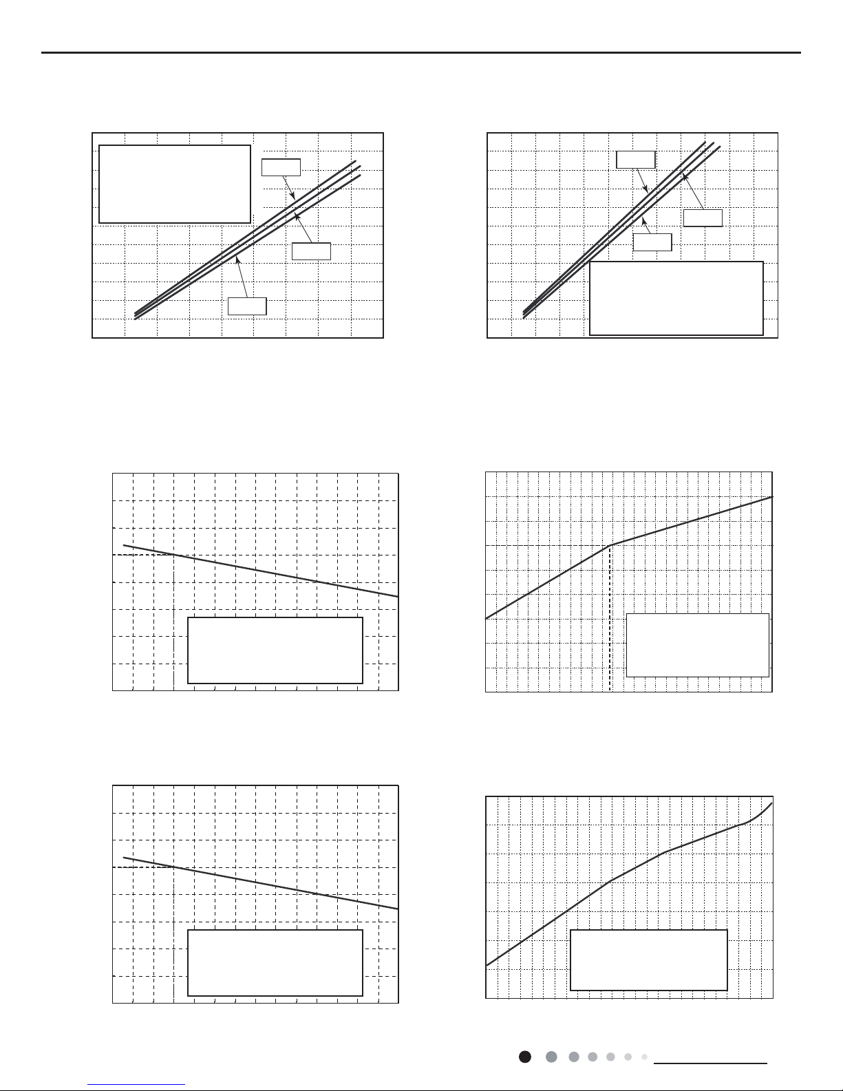
2.2 Operation Characteristic Curve
Cooling Heating
0 10 20 30 40 50 60 70 90 0 10 20 30 40 50 60 70 80 90 100 120110
80
11
10
9
8
7
6
5
4
3
2
1
0
11
10
9
8
7
6
5
4
3
2
1
0
220V
230V
240V
220V
230V
240V
Current (A)
Current (A)
Conditions
Indoor:DB27°C/WB19°C
Outdoor:DB35°C/WB24°C
Indoor air flow:Super High
Pipe length:5m
Conditions
Indoor:DB20°C/WB15°C
Outdoor:DB7°C/WB6°C
Indoor air flow:Super High
Pipe length:5m
Compressor speed (rps) Compressor speed (rps)
2.3 Capacity Variation Ratio According to Temperature
Capacity ratio(%)
Outdoor temp. (°C)
Capacity ratio(%)
Outdoor temp. (°C)
Capacity ratio(%)
Capacity ratio(%)
Outdoor temp. (°C)
-20 -15 -10 -5 0 5 10
110
120
130
100
90
80
70
60
50
40
50
60
70
80
90
100
110
120
130
32 33 34 35 36 37 38 39 40 41 42 43 44 45 46
50
60
70
80
90
100
110
120
130
32 33 34 35 36 37 38 39 40 41 42 43 44 45 46
Conditions
Indoor:DB27°C/WB19°C
Indoor air flow:High
Pipe length:5m
Conditions
Indoor:DB27°C/WB19°C
Indoor air flow:High
Pipe length:5m
Condition
Indoor:DB20°C
/WB15°C
Indoor air flow:
High
Pipe length:5m
–15 –10 –5 5
110
100
90
80
70
60
50
40
0 7 10
Conditions
Indoor:DB20°C/WB15°C
Indoor air flow:Super High
Pipe length:5m
Outdoor temp.(°C)
Cooling
Heating operation ambient temperature range is -20°C~24°C
Heating operation ambient temperature range is -15°C~24°C
Cooling
Heating
Heating
7
Technical Information
Service Manual
2.4 Cooling and Heating Data Sheet in Rated Frequency
Instruction:
T1: Inlet and outlet pipe temperature of evaporator
T2: Inlet and outlet pipe temperature of condenser
P: Pressure at the side of big valve
Connection pipe length:5 m.
Cooling:
Heating:
Rated cooling
condition(°C) (DB/WB)
Model
Pressure of gas pipe
connecting indoor
and outdoor unit
Inlet and outlet pipe
temperature of heat
exchanger
Fan speed
of indoor
unit
Fan speed
of outdoor
unit
Compressor
revolution (rps)
Indoor Outdoor P (MPa) T1 (°C) T2 (°C)
27/19 35/24
09K 0.9 to 1.1 12 to 14 75 to 37 Super High High 63
12K 0.8 to 1.0 10 to 12 85 to 43 Super High High 70
Rated heating
condition(°C) (DB/WB)
Model
Pressure of gas pipe
connecting indoor
and outdoor unit
Inlet and outlet pipe
temperature of heat
exchanger
Fan speed
of indoor
unit
Fan speed
of outdoor
unit
Compressor
revolution (rps)
Indoor Outdoor P (MPa) T1 (°C) T2 (°C)
20/15 7/6
09K 2.4 to 2.6 70 to 35 2 to 4 Super High High 69
12K 2.4 to 2.6 70 to 35 2 to 4 Super High High 72
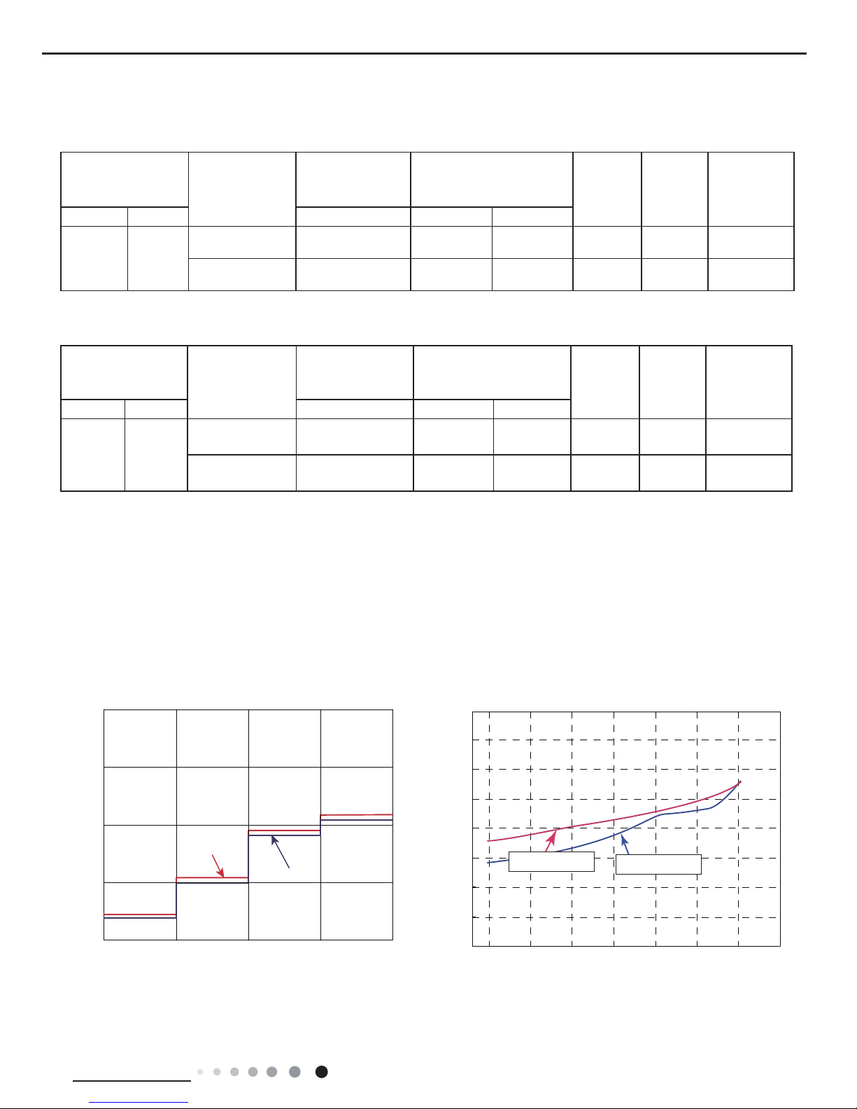
2.5 Noise Curve
Indoor side noise when blowing Outdoor side noise when blowing
Indoor fan motor rotating speed
Compressor frequency(Hz)
Noise/dB(A)
50
60
30
40
20
Low
Middle
High
Super High
12K
09K
40
42
44
46
48
50
52
54
56
20 4030 50 60 70 80 90
Noise dB(A)
09&12K Cooling
09&12K Heating
8
Technical Information
Service Manual
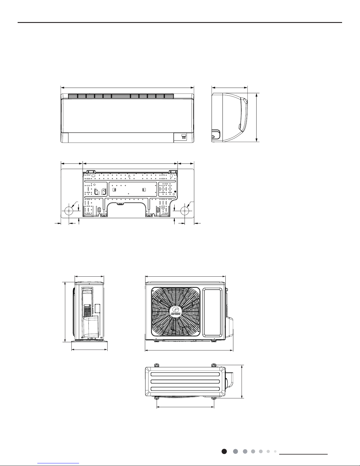
3. Outline Dimension Diagram
3.1 Indoor Unit
Φ55
Φ55
41.3
41.3
54
54.5
120.5 548.5
770
201
283
103
3.2 Outdoor Unit
unit:mm
unit:mm
712
776
257
320
540
286
510
9
Technical Information
Service Manual
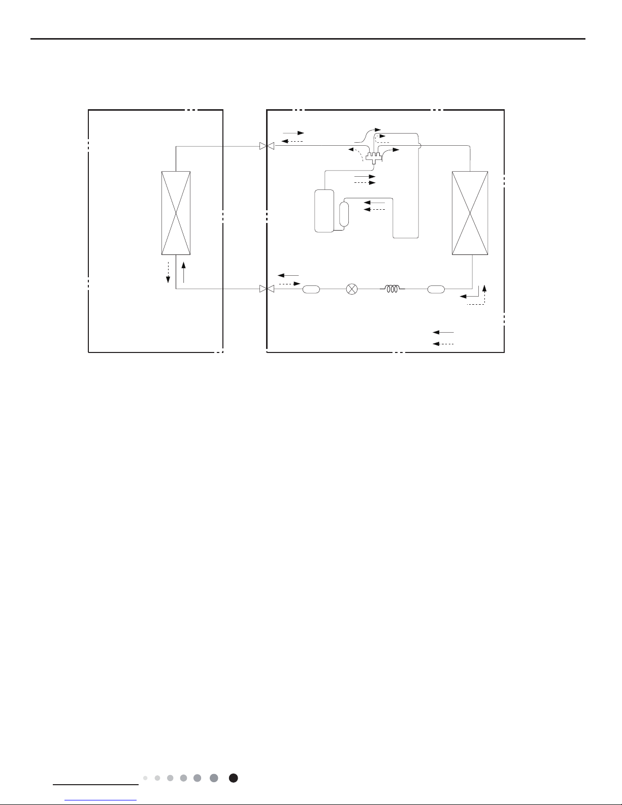
4. Refrigerant System Diagram
Indoor unit
Outdoor unit
COOLING
HEATING
4-Way valve
Discharge
Suction
Heat
exchanger
(evaporator)
Heat
exchanger
(condenser)
Valve
Valve
Liquid pipe
side
Gas pipe
side
Strainer
Electron
expansion
valve
Strainer
Capillary
Accumlator
Compressor
Connection pipe specication:
Liquid pipe:1/4" (6mm)
Gas pipe:3/8" (9.52mm)
10
Technical Information
Service Manual
5. Electrical Part
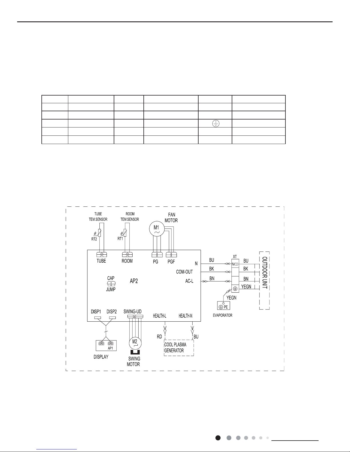
5.1 Wiring Diagram
● Indoor Unit
●Instruction
Symbol Symbol Color Symbol Symbol Color Symbol Name
WH White GN Green CAP Jumper cap
YE Yellow BN Brown COMP Compressor
RD Red BU Blue Grounding wire
YEGN Yellow/Green BK Black / /
VT Violet OG Orange / /
Note: Jumper cap is used to determine fan speed and the swing angle of horizontal lover for this model.
3
2
(optional)
11
Technical Information
Service Manual
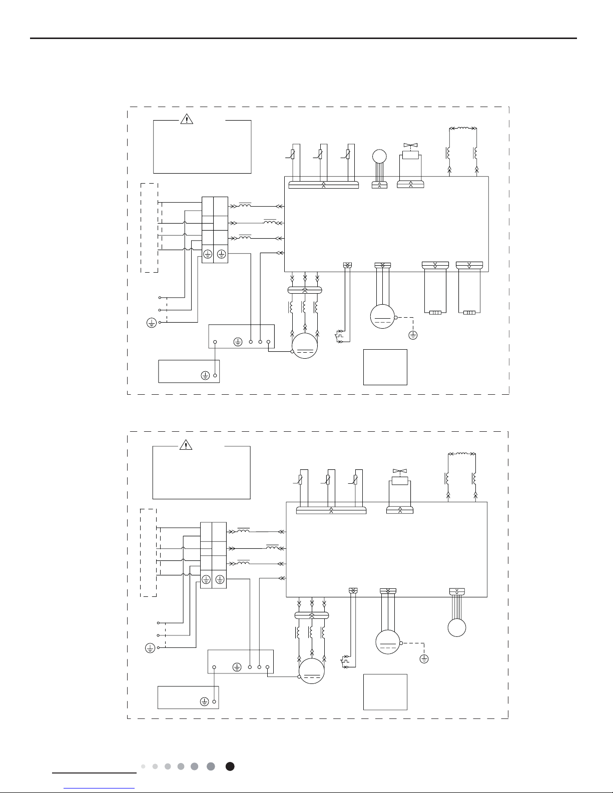
● Outdoor Unit
(1)GWH09KF-K3DNA6G/O(CB146W36201), GWH12KF-K3DNA6G/O(CB146W36101)
(2)GWH09KF-K3DNA6G/O(CB146W36200), GWH12KF-K3DNA6G/O(CB146W36100)
These wiring diagrams are subject to change without notice; please refer to the one supplied with the unit.
/
5'
<(
%8
:$51,1*
PLQXWHVWRSUHYHQWWKHULVN
SRZHUHGRIIIRUOHVVWKDQ
UXQQLQJVWRSSLQJRUKDVEHHQ
WHUPLQDOZKHQWKHPDFKLQHLV
3OHDVHGRQWWRXFKDQ\
RIHOHFWULFVKRFN
97
97
%1
%8
%1
%.
%8
+($7+($7
+HDWHU
+HDWHU
%DQG
&RPS
%DQG
%RWWRP
(+
%/2&.
(;+$867
2875220
28778%(
(;3$16,21
9$/9(
<(*1
<(*1
<(*1
<(*1
<(*1
<(*1
3(
3(
<(*1
6+((7
%2;
0,',62/$7,21
(/(&75,&$/
;
5,1*
0$*1(7,&
N
N
N
5,1*
0$*1(7,&
5,1*
0$*1(7,&
5'
9$/9(
:$<
:$<
<9
(/(&7521,&
(.9
&1
(+
6(1625
57
57
57
7(03
6(1625
7(03
6(1625
7(03
%1
%8
/
5($&725
/
/
3(
&208
$&/
1
/
$30DLQ%RDUG
BU
BK
BN
8
9
:
6$7
29&&203
5'
3(
3(
0
)$1
2)$1
&1
1
/
32:(5
1
/
1
;7
7(50,1$/
29(5/2$5'
3527(&725
/;
/;
&203
&203
<(
5'
8
9
:
%8
/
3(
/
,1'22581,7
JURXQGRQO\
LURQVKHOOPRWRU
DSSOLHVWRWKH
0RWRU
127(
02725
/
/
3(
/
%8
:
9
8
5'
<(
&203
&203
/;
/;
3527(&725
29(5/2$5'
7(50,1$/
;7
/
1 1
32:(5
/
1
&1
2)$1
)$1
0
3(
3(
5'
29&&203
6$7
:
9
8
BN
BK
BU
$30DLQ%RDUG
/
1
$&/
&208
3(
/
/
5($&725
/
%8
%1
7(03
6(1625
7(03
6(1625
7(03
57
57
57
6(1625
&1
(.9
(/(&7521,&
<9
:$<
:$<
5'
0$*1(7,&
5,1*
0$*1(7,&
5,1*
N
N
N
0$*1(7,&
5,1*
;
(/(&75,&$/
0,',62/$7,21
%2;
6+((7
<(*1
3(
3(
<(*1
<(*1
<(*1
<(*1
<(*1
<(*1
9$/9(
(;3$16,219$/9(
28778%(
2875220
(;+$867
%/2&.
%8
%.
%1
%8
%1
97
97
RIHOHFWULFVKRFN
3OHDVHGRQWWRXFKDQ\
WHUPLQDOZKHQWKHPDFKLQHLV
UXQQLQJVWRSSLQJRUKDVEHHQ
SRZHUHGRIIIRUOHVVWKDQ
PLQXWHVWRSUHYHQWWKHULVN
:$51,1*
%8
<(
5'
,1'22581,7
127(
0RWRU
DSSOLHVWRWKH
LURQVKHOOPRWRU
JURXQGRQO\
02725
12
Technical Information
Service Manual
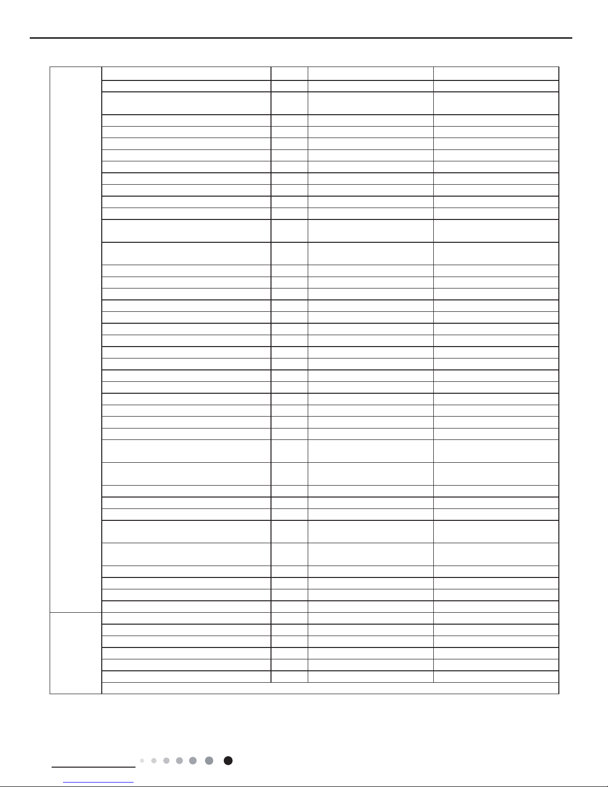
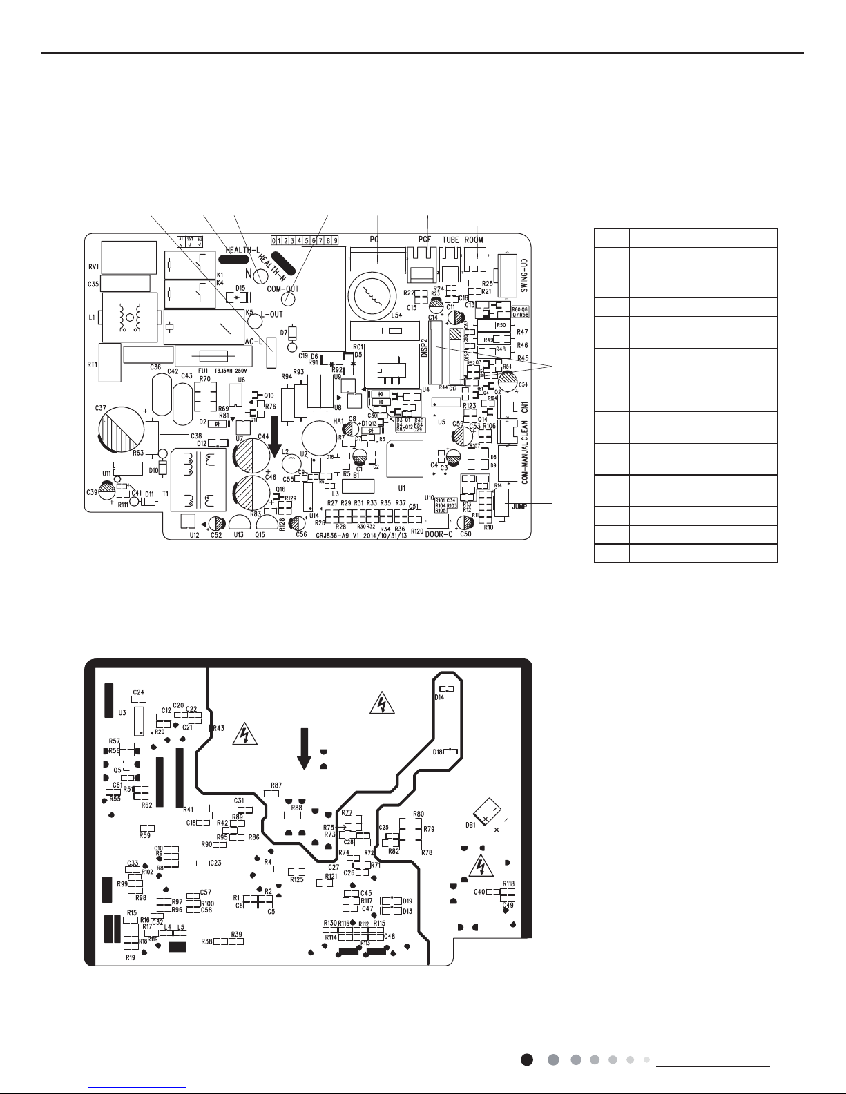
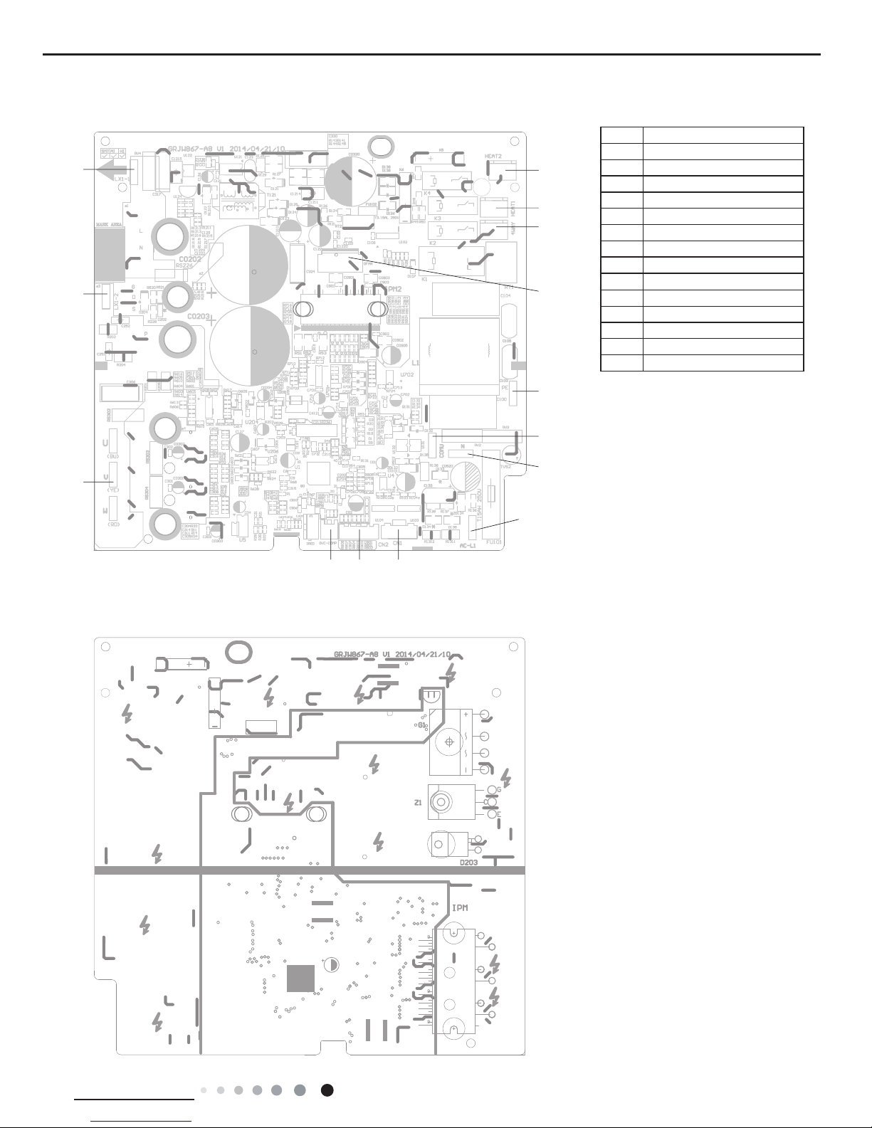
5.2 PCB Printed Diagram
Indoor Unit
●TOP VIEW
●BOTTOM VIEW
No.
Name
1 Interface of live wire
2
Interface of live wire for
health function
3 Interface of neutral wire
4
Interface of neutral wire for
health function
5
Interface of neutral wire and
live wire communication
6
Control interface of PG
motor
7
Feedback interface of
indoor fan
8
Indoor tube temperature
sensor interface
9
Ambient temperature
sensor interface
10 Up & down swing
11 Interface of display
12 Jumper cap
1 2 3 4 5 6 7 8 9
10
11
12
13
Technical Information
Service Manual
1
2
3
4
5
6
7
8
9
10
11
121314
Outdoor Unit
●TOP VIEW
●BOTTOM VIEW
No. Name
1 Compressor
2 Reactor 2
3 Reactor 1
4 Chassis electric heating
5 Compressor electric heating
6 4-way valve
7 DC fan
8 Earthing wire
9
Communication wire
10 Neutral wire
11 Live wire
12 Electronic expansion valve
13 Temperature sensor
14 Overloard
14
Technical Information
Service Manual
6. Function and Control
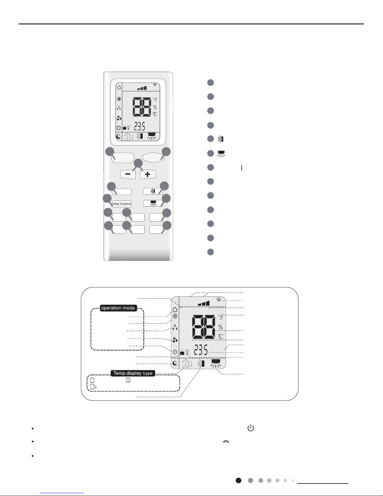
6.1 Remote Controller Introduction
Introduction for buttons on remote controller
Note:
After putting through power, air conditioner will give out a sound and operation indicator "
" is ON (red indicator). You can operate the air
conditioner through the remote controller.
At ON status, after each pressing button on remote controller, the signal icon "
" on remode controller will ash once. Air conditioner will
give out a sound, which indicates the signal has been sent to air conditioner.
At OFF status, display screen on remote controller displays set temperature. At on status, display screen on remote controller displays
the corresponding start up function’s icon.
Buttons on remote controller
Introduction for icons on display screen
ON/OFF Button
2
3
1
5
6
4
9
10
8
12
13
11
MODE Button
+/- Button
X-FAN Button
TEMP Button
TURBO Button
SLEEP Button
LIGHT Button
Button
HEALTH SAVE Button
7
Button
TIMER Button
FAN Button
FAN
AUTO
OPER
HEALTH
AIR
FILTER
TURBO
ON/OFF
X-FAN
HOUR
HUMIDITY
ON/OFF
MODE
FAN
X-FAN
TURBO
TEMP
TIMER
SLEEP
LIGHT
2
10
7
9
12
8
3
11
6
5
13
4
1
Child lock
Left&right swing
Sleep mode
Auto mode
Air mode
Cool mode
Heat mode
Fan mode
Dry mode
Up&down swing
:Indoor ambient temp.:Set temp.
:Outdoor ambient temp.
FAN
OPER
AUTO
HEALTH
AIR
FILTER
TURBO
ON/OFF
X-FAN
HOUR
HUMIDITY
TIMER ON/TIMER OFF
Set time
Light
Send signal
Health mode
X-fan
Set fan speed
Set temperature
Turbo mode
Temp. display type
Operation mode
15
Technical Information
Service Manual
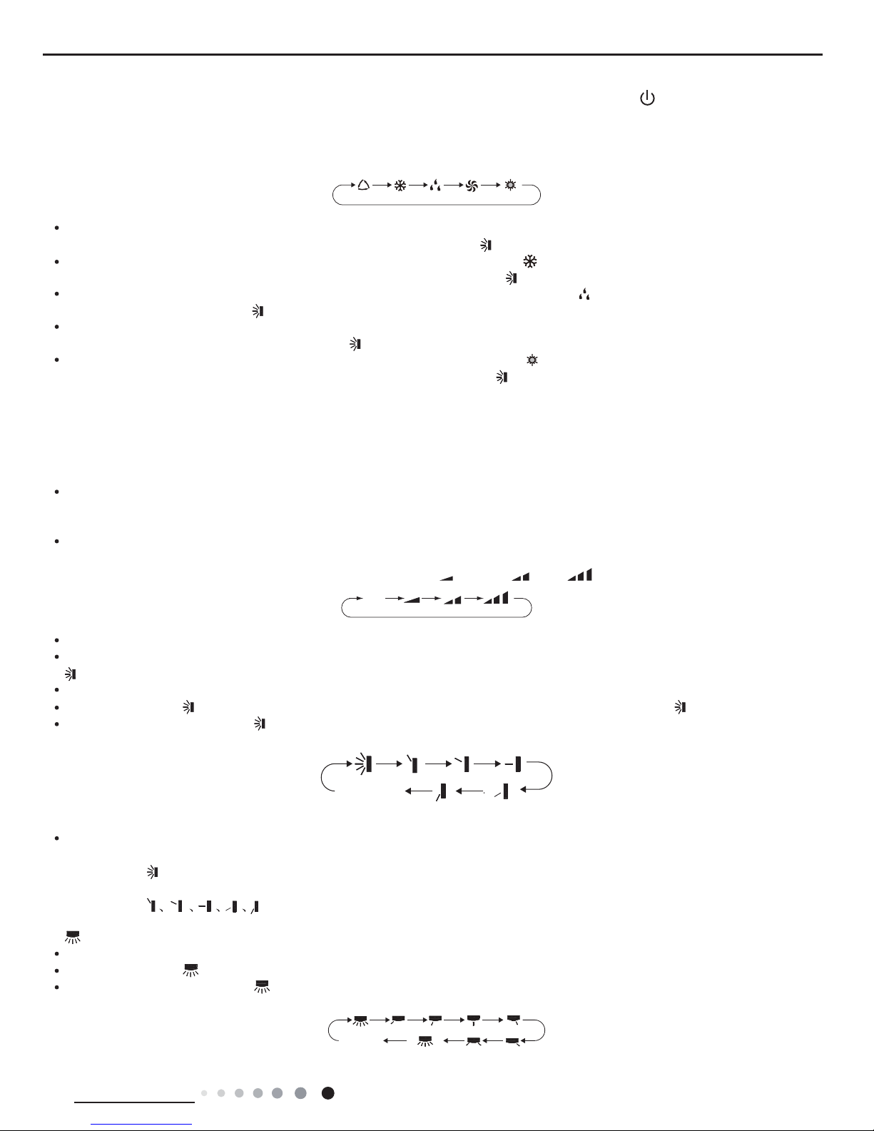
1.ON/OFF button
Press this button can turn on or turn off the air conditioner. After turning on the unit,operation indicator "
" on indoor unit is ON (green
indicator. Color may be differ-ent for different models)and indoor unit gives out a sound.
2.MODE button
Press this button can select your required operation mode.
AUTO COOL DRYF AN HEAT
After selecting auto mode, air conditioner will operate automatically according to ambient temperature. Set temperature can’t be adjusted
and also can’t be displayed. Press "FAN" button can adjust fan speed. Press "
" button can adjust swing angle.
After selecting cool mode, air conditioner operates under cool mode. Cool indicator "
" on indoor unit is ON. You can press "+" or "-"
button to adjust set temperature. Press "FAN" button can adjust fan speed. Press "
" button can adjus t swing angle.
After selecting dry mode, air conditioner operates under dry mode at low speed. Dry indicator "
" on indoor unit is ON. Under dry mode,
fan speed can’t be adjusted. Press "
" button to adjust swing angle.
After selecting fan mode, air conditioner operates only under fan mode, All mode indicators on indoor unit is OFF. Operation indicator is
ON. Press "FAN" button can adjust fan speed. Press "
" button to adjust swing angle.
After selecting heat mode, air conditioner operates under heat mode. Heat indicator "
" on indoor unit is ON. You can press "+" or "-"
button to adjust set temperature. Press "FAN" button to adjust fan speed. Press "
" button to adjust swing angle. (Cooling only unit can’t
receive the signal for heating mode.)
Note:
For preventing cold wind, after starting up heating mode, indoor fan will blow fan afterdelaying 1-5min. (Details time is decided by indoor
ambient temperature) Temperature setting range on remote controller: 16
o
C~30oC(61oF~86oF) . Fan speed setting range: auto, low speed,
medium speed and high speed.
3."+" or "-" button
After each pressing of "+" or "-" button, it can increase or decrease set temperature 1
o
C(1oF~2oF) . Hold "+" or "-" button, 2s later, set
temperature on remote controller will change quickly. After reaching to your required time, loosen the button. Temperature indicator on
indoor unit will also change accordingly. (Temperature can’t be adjusted under auto mode)
Under TIMER ON, TIMER OFF or Clock setting, you can press "+"or "-" button to adjust time. (Refer to TIMER button for details)
4.FAN button
Pressing this button can set fan speed circularly as: auto (AUTO), low(
), medium( ), high( ).
Note:
Under AUTO Speed,IDU fan motor will adjust the fan speed (high, medium or low speed) according to ambient temperature.
Fan speed under dry mode is low speed.
5.
button
Press this button to start or stop up & down swing function.The remote controller defaults to simple swing condition.
Press "+" button and "
" button at the same time at unit OFF to switch between simple swing and static swing; " " blinks for 2 seconds.
In static swing condition, pressing "
" button, the swing angle of up & down louver changes as below:
If the unit is turned off during swing operation,the louver will stop at present position.
Note:
When selecting "
" with remote controller, it’s auto swing. Horizontal louver of air conditioner will swing up&down automatically at the
maximum angle.
When selecting "
" with remote controller, it is the xed position swing. Horizontal louver of air conditioner will stop at
that position as shown by the icon to swing.
6.
button
Press this button to start or stop left & right swing function. The remote controller defaults to simple swing condition.
Press "+" button and "
" button at the same time at unit OFF to switch between simple swing and static swing; blinks for 2 seconds.
In static swing condition, pressing "
" button, the swing angle of left & right louver changes as below:
AUTO
no display
(horizontal louvers
stops at current
position)
no display
(horizontal
louvers stops
at current
position)
(swing angle is
displayed
dynamically)
16
Technical Information
Service Manual
If the unit is turned off during swing operation,the louver will stop at present position.
When selecting "
" with remote controller, it is the xed position swing. Horizontal louver of air conditioner will stop at
that position as shown by the icon to swing.
When selecting "(
swing angle is displayed dynamically
)" it’s the circulating swing. Horizontal louver of air conditioner will swing circularly according to
the angle as shown by the icon.
Note:
There is no this function for the units. If press this key, the main unit will click, but it also runs under original status.
7.HEALTH/SAVE button
After pressing HEALTH button, remote controller will switch circularly as below: "HEALTH"→"AIR"→"AIR HEALTH"→"no display"
When selecting "HEALTH" by remote controller, HEALTH function will be started up.
When selecting "AIR" by remote controller, AIR function will be started up.
When selecting "AIT HEALTH", AIR and HEALTH function will be started up.
When there’s no display on remote controller, AIR and HEALTH function will be turned off.
AIR function is applicable for some models.
SAVE function:
Under cool mode, press SAVE button and the unit will operate under SAVE mode. Dual-8nixie tube on remote controller displays "SE".
Air conditioner will operate at auto speed. Set temperature can’t be adjusted. Press SAVE button again to exit SAVE mode. Air conditioner
turn back to original set speed and set temperature.
This function is applicable to partial of models.
8.X-FAN button
After pressing this button under cooling or dry mode, remote controller displays the character of "X-FAN" and X-FAN function is started up.
Press this button again to cancel X-FAN function. The character of "X-FAN" will disappear.
Note:
After starting up X-FAN function, when turning off the unit, indoor fan will continue to operate for a while at low speed to dry the residual
water inside the indoor unit.
When the unit operates under X-FAN mode, press "X-FAN" button can turn off X-FAN function. Indoor fan stops operation immediately.
9.TEMP button
Press this button can see indoor set temperature, indoor ambient temperature or outdoor ambient temperature on indoor unit’s display.
Temperature is set circularly by remote controller as below:
When selecting "
" by remote controller or no display, temperature indicator on indoor unit displays set temperature.
When selecting "
" by remote controller, temperature indicator on indoor unit displays indoor ambient temperature.
When selecting "
" by remote controller, temperature indicator on indoor unit displays outdoor ambient temperature.
Note:
Outdoor ambient temperature display may can’t be selected for some models. When indoor unit receives "
" signal, it displays indoor
set temperature.
Only for the model whose indoor unit has dual-8 display.
10.TIMER button
At ON status, press this button once can set TIMER OFF. The character of HOUR and OFF will ash.Press "+" or "-" button within 5s
can adjust the time of TEMER ON. After each pressing of "+" or "-" button, time will increase or decrease half an hour. When holding "+"
or "-" button, 2s later, the time will change quickly until to reach to your required time. After that, press "TIMER" button to conrm it. The
character of HOUR and OFF won't ash again.
Cancel TIMER OFF: Press "TIMER" button again under TIMER OFF status.
At OFF status, press this button once can set TIMER ON. Please refer to TIMER off for detailed operation.
Cancel TIMER ON: Press "TIMER" button again under TIMER ON status.
Note:
Time setting range: 0.5-24 hours.
Time interval between two operations can’t exceed 5s. Otherwise, remote controller will exit the setting status automatically.
11.TURBO button
When pressing this button under cooling or heating mode, air conditioner will enter into quick cooling or quick heating mode. The
character of "TURBO" is displayed on remote controller. Press this button again to exit turbo function and the character of "TURBO" will be
disappeared on remote controller.
12.SLEEP button
Press this button under cooling, heating mode can start up sleep function."
" icon will be displayed on remote controller. Press this button
again to cancel sleep function. "
" icon on remote controller will be displayed.
13.LIGHT button
Press this button can turn off the light for indoor unit’s display. "
" icon on remote controller will disappear. Press this button again to turn
on the light for indoor unit’s display. "
" icon on remote controller will be displayed.
no display
17
Technical Information
Service Manual
Function introduction for combination buttons
Child lock function
Press "+" and "-" buttons simultaneously can turn on or turn off child lock function. When child lock function is started up, "
" icon will be
displayed on remote controller. If operate remote controller "
" icon will ash three times, while remote controller won’t send signal.
Switchover function for temperature display
After turning off the unit by remote controller, press "-" button and "MODE" button simultaneously to switch between
o
C and °F.
Operation guide
1. After putting through the power, press "
" button on remote controller to turn on the air conditioner.
2. Press "
" button to select your required mode: AUTO, COOL, DRY, FAN, HEAT.
3. Press "+" or "-" button to set your required temperature. (Temperature can’t be adjusted under auto mode).
4. Press "
" button to set your required fan speed: auto, low, medium and high speed.
5. Press "
" button to select fan blowing angle.
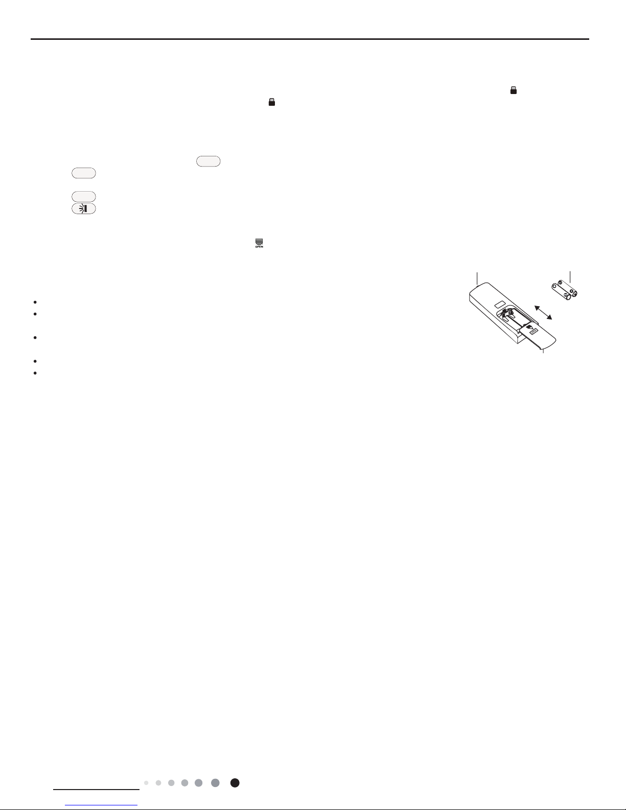
Replacement of batteries in remote controller
1. Press the back side of remote controller marked with "
", as shown in the g, and then push out the cover of battery box along the arrow
direction.
2. Replace two 7# (AAA 1.5V) dry batteries, and make sure the position of "+" polar and "-" polar are correct.
3. Reinstall the cover of battery box.
NOTICE
During operation, point the remote control signal sender at the receiving window on indoor unit.
The distance between signal sender and receiving window should be no more than 8m, and there should
be no obstacles between them.
Signal may be interfered easily in the room where there is uorescent lamp or wireless telephone; remote
controller should be close to indoor unit during operation.
Replace new batteries of the same model when replacement is required.
When you don’t use remote controller for a long time, please take out the batteries.
If the display on remote controller is fuzzy or there’s no display, please replace batteries.
ON/OFF
MODE
FAN
signal sender battery
Cover of battery box
remove
reinstall

18
Installation and Maintenance
Service Manual
6.2 Brief Description of Modes and Functions
1.Temperature Parameters
●Indoor preset temperature (Tpreset)
●Indoor ambient temperature (Tamb.)
2. Basic Functions
Once energized, in no case should the compressor be restarted within less than 3 minutes. In the situation that memory function is
available, for the rst energization, if the compressor is at stop before de-energization, the compressor will be started without a 3-minute
lag; if the compressor is in operation before de-energization, the compressor will be started with a 3-minute lag; and once started, the
compressor will not be stopped within 6 minutes regardless of changes in room temperature;
(1)COOL mode
①
The condition and process of cooling
If Tamb≥Tpreset COOL mode will act, the compressor and outdoor fan will run, and the indoor fan will run at the set speed.
If Tamb≤Tpreset-2°C, the compressor will stop, the outdoor fan will delay 30 seconds to stop, and the indoor fan will run at the set
speed. If Tpreset-2°C≤Tamb ≤Tpreset , the unit will keep running in the previous mode. In this mode, the reversal valve will not be
powered on and the temperature setting range is 16 ~30°C.
②
Protection function
●Overcurrent protection
If total current is high, the compressor will run in limited frequency. If total current is too high, the compressor will stop, the outdoor fan
will delay 30 seconds to stop, indoor unit will display E5 and outdoor yellow light will blink 5 times.
●Antifreezing protection
When the antifreezing protection is detected, the compressor will stop, the outdoor fan will stop after 30 seconds, and the indoor fan
and swing motor will keep running in the original mode. When antifreezing protection is eliminated and the compressor has stopped for
3 minutes, the compressor will resume running in the original mode.
(2) Dehumidifying mode
①
Working conditions and process of dehumidifying
If Tamb.>Tpreset, the unit will enter cooling and dehumidifying mode, in which case the compressor and the outdoor fan will operate
and the indoor fan will run at low speed.
If Tpreset -2°C≤Tamb.≤Tpreset, the compressor remains at its original operation state.
If Tamb.< Tpreset -2°C, the compressor will stop, the outdoor fan will stop with a time lag of 30s, and the indoor fan will operate at low
speed.
②
Protection function
Protection is the same as that under the cooling mode.
(3) HEAT mode
①
The condition and process of heating
If Tamb≤Tpreset+2°C, HEAT mode will act, the compressor, outdoor fan and reversal valve will run, the indoor fan will delay 3min to
stop at the latest.
If Tpreset +2°C≤Tamb≤Tpreset +5°C,the unit will keep running in the original mode.
If Tamb≥Tpreset +5°C, the compressor will stop, the outdoor fan will delay 30sec to stop and indoor fan will blow 60S at low speed, the
fan speed cannot be shifted within blow residual heat.
●In this mode, the temperature setting range is 16 ~30°C.
●The air conditioner will adjust the running frequency of the compressor automatically according to the change of ambient temperature.
●When the unit is turned off in HEAT mode, or switched to other mode from HEAT mode, the four-way valve will be powered off after
the compressor stops.
②
The condition and process of defrosting
When frost is detected in the condenser, the system will enter into defrosting state. When defrosting starts, the compressor and indoor
fan will stop, and the outdoor fan and four-way valve will delay 30 seconds to stop. The compressor will start after 15 seconds and
then defrosting will be started. When the compressor has run for 7 minutes or defrosting is nished, the compressor will stop. After 30
seconds the four-way valve opens and after another 60 seconds, the compressor and outdoor fan resume running. The indoor fan will
delay 3 minutes to run at the latest and heating indicator on indoor unit OFF 0.5s and ON 10s.
③
Protection function
●Anti-cold-wind protection
In HEAT mode, in order to prevent the indoor unit from blowing out cold wind, each time the compressor starts, the indoor fan will delay
3 minutes after the compressor to run at the latest and it can adjust fan speed automatically when temperature is low.
●Overcurrent protection
Overcurrent protection is the same with that in COOL mode.
●Cold air prevention
The unit is started under heating mode (the compressor is ON):

19
Installation and Maintenance
Service Manual
1.In the case of Tindoor amb. <24°C: if T≤tube40°C and the indoor fan is at stop state, the indoor fan will begin to run at low speed with
a time lag of 2 minutes. Within 2 minutes, if Ttube>40°C, the indoor fan also will run at low speed; and after1-minute operation at low
speed, the indoor fan will be converted tooperation at preset speed. Within 1-minute low speed operation or 2-minute non-operation, if
Ttube>42°C, the fan will run at present speed.
2.In the case of Tindoor amb.≥24°C: if Ttube≤42°C, the indoor fan will run at low speed, and afterone minute, the indoorfan will be
converted to preset speed. Within one-minute low speed operation, if Ttube>42°C, the indoor fan will beconvertedto preset speed.
Note:T
indoor amb.
indicated in 1 and 2 refers to, under initially heating mode, the indoor ambient temperature before the command to start
the compressor is performed according to the program, or after the unit is withdrawn from defrost, the indoor ambient temperature
before the defrost symbol is cleared.
●Total current up and frequency down protection
If the total current I
total
≤W, frequency rise will be allowed; if I
total
≥X, frequency rise will not be allowed; if I
total
≥Y, the compressor will run at
reduced frequency; and if I
total
≥Z, the compressor will stop and the outdoor fan will stop with a time lag of 30s.
(4) Fan Mode
Under the mode, the indoor fan will run at preset speed and the compressor, the outdoor fan, the four-way valve and the electric heater
will stop.
Under the mode, temperature can be set within a range of 16 - 30°C.
(5) AUTO Mode
①
The condition and process of auto
a. When Tamb.≥26°C the unit will operate at Cooling mode. In that case, the set temperature will be 25°C.
b. When Tamb.≤22°C the heat pump unit will operate at Heating mode. In that case, the set temperature will be 20°C; the cooling-only
unit will operate at Fan mode and the set temperature will be 25°C.
c. When 23°C≤Tamb.≤25°C the unit will keep its operation status but if it is rstly energized, the unit will operate at Fan mode.
d. When unit operates at Auto mode, the frequency of compressor will be the same as that in Cooling mode if the unit is coolingwhile it
will be the same as that in the Heating mode if the unit is heating.
②
Protection function
a.In cooling operation, protection is the same as that under the cooling mode;
b.In heating operation, protection is the same as that under the heating mode;
c.When ambient temperature changes, operation mode will be converted preferentially. Once started, the compressor will remain
unchanged for at least 6 minutes.
(6) Common Protection Functions and Fault Display under COOL, HEAT, DRY and AUTO Modes
①
Overload protection
Ttube: measured temperature of outdoor heat exchanger under cooling mode; and measured temperature of indoor heat exchanger
under heating mode.
1) Cooling overload
a. If T tube52, the unit will return to its original operation state.
b. If T tube55, frequency rise is not allowed.
c. If T tube58, the compressor will run at reduced frequency.
d. If T tube62, the compressor will stop and the indoor fan will run at preset speed.
2) Heating overload
a. If T tube52, the unit will return to its original operation state.
b. If T tube55, frequency rise is not allowed.
c. If T tube58, the compressor will run at reduced frequency.
d. If T tube62, the compressor will stop and the indoor fan will blow residue heat and then stop.
②
Exhaust temperature protection of compressor
If exhaust temperature 98, frequency is not allowed to rise.
If exhaust temperature 103, the compressor will run at reduced frequency.
If exhaust temperature 110, the compressor will stop.
If exhaust temperature 90 and the compressor has stayed at stop for at least 3 minutes, the compressor will resume its operation.
③
Communication fault
If the unit fails to receive correct signals for durative 3 minutes, communication fault can be justied and the whole system will stop.
④
Module protection
Under module protection mode, the compressor will stop. When the compressor remains at stop for at least 3 minutes, the compressor
will resume its operation. If module protection occurs six times in succession, the compressor will not be started again.
⑤
Overload protection
If temperature sensed by the overload sensor is over 115, the compressor will stop and the outdoor fan will stop with a time lag of 30
seconds.
⑥
If temperature is below 95, the overload protection will be relieved. If voltage on the DC bus is below 150V or over 420V, the
compressor will stop and the outdoor fan will stop with a time lag of 30 seconds. When voltage on the DC bus returns to its normal
value and the compressor has stayed at stop for at least 3 minutes, the compressor will resume its operation.
20
Installation and Maintenance
Service Manual
3. Other Controls
(1) ON/OFF
Press the remote button ON/OFF: the on-off state will be changed once each time you press the button.
(2) Mode Selection
Press the remote button MODE, then select and show in the following ways: AUTO, COOL, DRY, FAN, HEAT, AUTO.
(3) Temperature Setting Option Button
Each time you press the remote button TEMP+ or TEMP-, the setting temperature will be up or down by 1°C. Regulating Range:
16~30°C, the button is useless under the AUTO mode.
(4) Time Switch
You should start and stop the machine according to the setting time by remote control.
(5) SLEEP State Control
①
Cooling mode
a. When initial temperature setting is 16~23°C, after turning on sleep function, temperature will increase 1°C every one hour. After
temperature is increased by 3°C, the unit will keep this temperature. After operation for 7 hours, temperature will decrease
1°C. After that, the unit will operate at this temperature all the time.
b. When initial temperature setting is 24~27°C, after turning on sleep function, temperature will increase 1°C every one hour. After
temperature is increased by 2°C, the unit will keep this temperature. After operation for 7 hours, temperature will decrease
1°C. After that, the unit will operate at this temperature all the time.
c. When initial temperature setting is 28~29°C, after turning on sleep function, temperature will increase 1°C every one hour. After
temperature is increased by 1°C, the unit will keep this temperature. After operation for 7 hours, temperature will decrease
1°C. After that, the unit will operate at this temperature all the time. When the initial temperature setting is 30°C, the unit will
operate under this temperature. After operation for 7 hours, temperature will decrease 1°C. After that, the unit will operate at this
temperature all the time.
②
Heating mode:
a. When initial temperature setting is 16°C, the unit operate under this temperature all the time.
b. When initial temperature setting is 17~20°C, after turning on sleep function, temperature will decrease 1°C every one hour. After
temperature is increased by 1°C, the unit will keep this temperature.
c. When initial temperature setting is 21~27°C, after turning on sleep function, temperature will decrease 1°C every one hour.
After temperature is increased by 2°C, the unit will keep this temperature.
d. When initial temperature setting is 28~30°C, after turning on sleep function, temperature will decrease 1°C every one hour. After
temperature is increased by 3°C, the unit will keep this temperature.
(6) Indoor Fan Control
Speed of indoor fan can be set as Turbo, High, Med., Low by remote control. In that case, fan will operate at super high, high, medium,
or low speed accordingly. The fan speed can also be set at Auto, which is as follows:
①
In heating mode: in auto heating or heating mode, the auto fan speed is as follows:
a. Tamb.≤Tpreset+1°C: indoor fan will operate at high speed;
b. Tpreset+1°C<Tamb.<Tpreset + 3°C: indoor fan will operate at med. speed;
c. Tamb.≥Tpreset + 3°C: indoor fan will operate at low speed; At least 210 seconds of operation shall be maintained for switchover
between high and low speeds, med. and low speeds, and high and low speeds.
②
In cooling mode, in auto cooling or cooling mode, the auto fan speed is as follows:
a. Tamb.≥Tpreset+2°C: indoor fan will operate at high speed.
b. Tpreset <Tamb.<Tpreset + 2°C: indoor fan will operate at med. speed;
c. Tamb.≤Tpreset: indoor fan will operate at low speed. At least 210 seconds of operation shall be maintained for switchover between
high and low speeds, med. and low speeds, and high and low speeds.
(7) Buzzer Control
The buzzer will send a “Di” sound when the air conditioner is powered up or received the information sent by the remote control or there
is a button input, the single tube cooler doesnt receive the remote control ON signal under the mode of heating mode.
(8) Auto button
If the controller is on, it will stop by pressing the button, and if the controller is off, it will be automatic running state by pressing the
button, swing on and light on, and the main unit will run based on the remote control if there is remote control order.
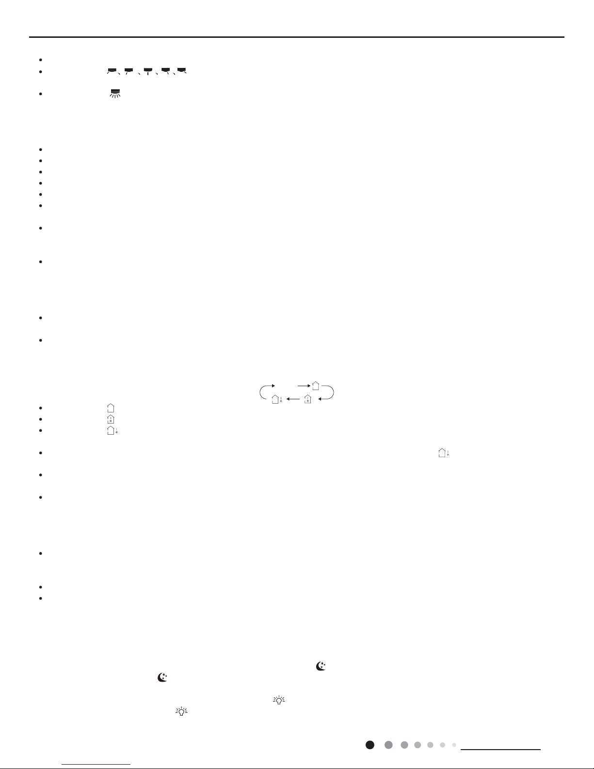
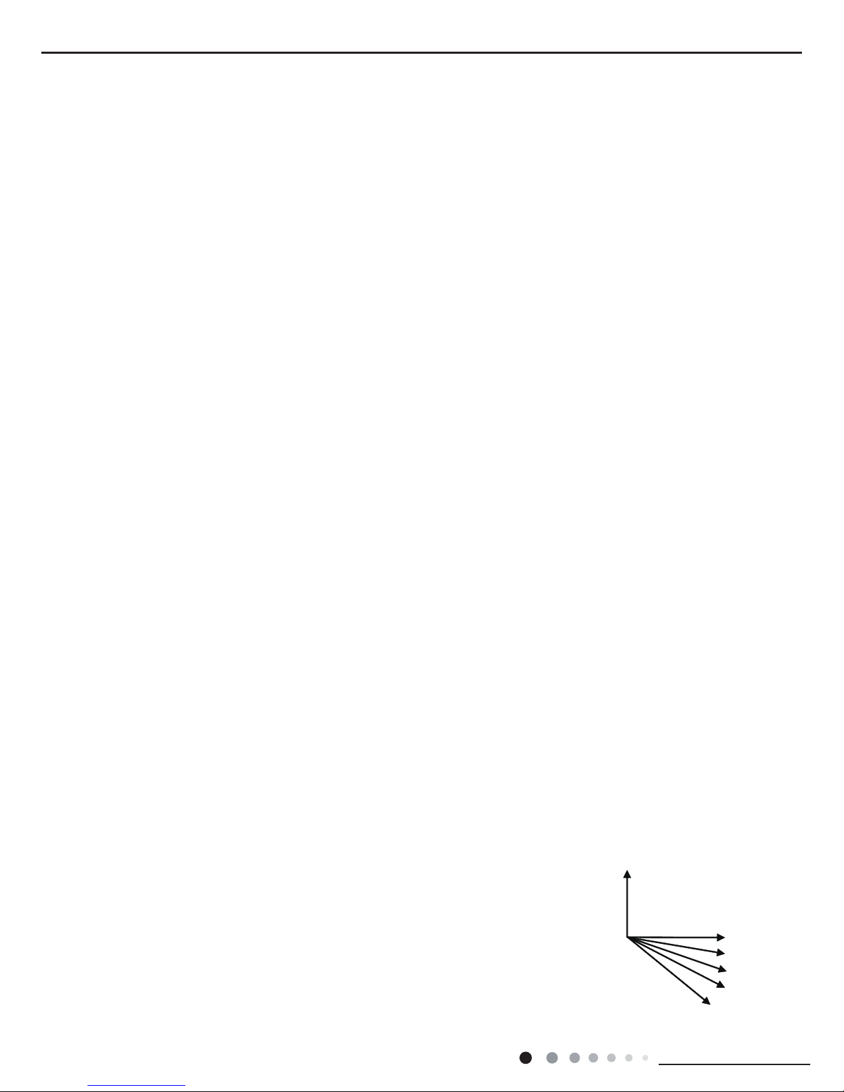
(9) Up-and-Down Swinging Control
When power on, the up-and-down motor will rstly move the air deector to o counter-clockwise,
close the air outlet. After starting the machine, if you dont set the swinging function, heating mode
and auto-heating mode, the up-and-down air deector will move to D clockwise; under other modes,
the up-and-down air deector will move to L1. If you set the swinging function when you start the
machine, then the wind blade will swing between L and D. The air deector has 7 swinging states:
Location L, Location A, Location B, Location C, Location D, Location L to Location D, stop at any
location between L-D (the included angle between L~D is the same). The air deector will be closed
at 0 Location, and the swinging is effectual only on condition that setting the swinging order and the
A
L
B
C
D
O(0
R
)
O(0 )
L1
A1
B1
C1
D1
cooling angle
R

21
Installation and Maintenance
Service Manual
inner fan is running. The indoor fan and compressor may get the power when air deector is on the default location.
(10) Display(NOTE:Nixie tube is not available for A8 panel.)
①
Operation pattern and mode pattern display
All the display patterns will display for a time when the power on, the operation indication pattern will display in red under standby
status. When the machine is start by remote control, the indication pattern will light and display the current operation mode (the mode
light includes: Cooling, heating and dehumidify). If you close the light key, all the display patterns will close.
②
Double-8 display
According to the different setting of remote control, the nixie light may display the current temperature (the temperature scope is
from 16 to 30°C) and indoor ambient temperature. The heating and air supply temperature will display 25°C under auto-mode, the
temperature will display 20°C under the heating mode, and under defrosting status, heating indicator on indoor unit OFF 0.5s and ON
10s.(If you set the fahrenheit temperature display, the nixie light will display according to fahrenheit temperature)
(11) Protection function and failure display
E2: Freeze-proong protection E4: Exhausting protection E5: Overcurrent protection E6: Communication failure
F1: Indoor ambient sensor start and short circuit (continuously measured failure in 5S)
F2: Indoor evaporator sensor start and short circuit (continuously measured failure in 5S)
F3: Outdoor ambient sensor start and short circuit (continuously measured failure in 30S)
F4: Outdoor condenser sensor start and short circuit (continuously measured failure in 30S, and dont measure within 10 minutes
after defrosted)
F5: Outdoor exhausting sensor start and short circuit (continuously measured failure in 30S after the compressor operated 3 minutes)
H3: Overload protection of compressor H5: Module protection PH: High-voltage protection PL: Low-voltage protection
P1: Nominal cooling and heating P2: Maximum cooling and heating P3: Medium cooling and heating
P0: Minimum cooling and heating
(12) Drying Function
You may start or stop the drying function under the modes of cooling and dehumidify at the starting status (The modes of automatism,
heating and air supply do not have drying function). When you start the drying function, after stop the machine by pressing the switch
button, you should keep running the inner fans for 2 minutes under low air damper (The swing will operate as the least status within 2
minutes, and other load is stopped), then stop the entire machine;When you stop the drying function, press the switch button will stop
the machine directly.
When you start the drying function, operating the drying button will stop the inner fans and close the guide louver.
(13) Power-failure memory function
What will be memorized includes modes, up and down wind blow, light, preset temperature, preset wind speed, general timing (no
memory for moment timing), and Fahrenheit /Celsius degree. When the unit is powered on again after power failure, operation
continues according to memorized content. If timing is not set by the last remote control command, the system will memorize the last
remote control command and operate in the mode specied in the last remote control command. If timing is set by the last remote
control command and power failure happens before the preset time, the system, as powered on again, will memorize the timing
function set by the last remote control command. Timing will be re-counted from the time at which the system is powered again. If
timing is set by the last remote control command and timing of start or stop is reached before power failure, the system, as powered
on again, will memorize operation state before power failure and will not perform timing action. Moment timing is out the range of
memory.
(14) Refrigerant recycling function (applicable when changing installation location or in maintenance)
1. Enter refrigerant recycling function
Within 5min after energizing (unit ON or OFF status is ok), continuously press LIGHT button for 3 times within 3s to enter refrigerant
recycling mode; Fo is displayed and refrigerant recycling function is started. At this moment, the maintenance people closes liquid
valve. After 5min, stick the thimble of maintenance valve with a tool. If there is no refrigerant spraying out, close the gas valve
immediately and then turn off the unit to remove the connection pipe.
2. Exit refrigerant recycling function
After entering refrigerant recycling mode, when receive any remote control signal or enter refrigerant recycling mode for 25min, the
unit will exit refrigerant recycling mode automatically If the unit is in standby mode before refrigerant recycling, it will be still in standby
mode after nishing refrigerant recycling; if the unit is in ON status before refrigerant recycling, it will still run in original operation
mode.
(15) Compulsive Defrosting Function
1. Start up compulsory defrosting function
Under ON status, set heating mode with remote controller and adjust the temperature to 16°C. Press “+, -, +, -, +,-” button
successively within 5s and the complete unit will enter into compulsory defrosting status. Meanwhile, heating indicator on indoor unit
will ON 10s and OFF 0.5s successively. (Note: If complete unit has malfunction or stops operation due to protection, compulsory
defrosting function can be started up after malfunction or protection is resumed.
2. Exit compulsory defrosting mode
After compulsory defrosting is started up, the complete unit will exit defrosting operation according to the actual defrosting result, and
the complete unit will resume normal heating operation.
22
Installation and Maintenance
Service Manual
1. Select the installation location according to the requirement of this manual.(See the requirements in installation
part)
2. Handle unit transportation with care; the unit should not
be carried by only one person if it is more than 20kg.
3. When installing the indoor unit and outdoor unit, a sufcient xing bolt must be installed; make sure the installation
support is rm.
4. Ware safety belt if the height of working is above 2m.
5. Use equipped components or appointed components during installation.
6. Make sure no foreign objects are left in the unit after nishing installation.
Electrical Safety Precautions:
7. Notes for Installation and Maintenance
Safety Precautions:
Important!
Please read the safety precautions carefully before
installation and maintenance.
The following contents are very important for installation
and maintenance.
Please follow the instructions below.
●The installation or maintenance must accord with the
instructions.
●Comply with all national electrical codes and local
electrical codes.
●Pay attention to the warnings and cautions in this
manual.
●All installation and maintenance shall be performed by
distributor or qualied person.
●All electric work must be performed by a licensed
technician according to local regulations and the
instructions given in this manual.
●Be caution during installation and maintenance. Prohibit
incorrect operation to prevent electric shock, casualty and
other accidents.
1. Cut off the power supply of air conditioner before
checking and maintenance.
2. The air condition must apply specialized circuit and
prohibit share the same circuit with other appliances.
3. The air conditioner should be installed in suitable
location and ensure the power plug is touchable.
4. Make sure each wiring terminal is connected rmly
during installation and maintenance.
5. Have the unit adequately grounded. The grounding
wire can’t be used for other purposes.
6. Must apply protective accessories such as protective
boards, cable-cross loop and wire clip.
7. The live wire, neutral wire and grounding wire of
power supply must be corresponding to the live wire,
neutral wire and grounding wire of the air conditioner.
8. The power cord and power connection wires can’t be
pressed by hard objects.
9. If power cord or connection wire is broken, it must be
replaced by a qualied person.
1. Avoid contact between refrigerant and re as it generates
poisonous gas; Prohibit prolong the connection pipe by
welding.
2. Apply specied refrigerant only. Never have it mixed with
any other refrigerant. Never have air remain in the refrigerant
line as it may lead to rupture or other hazards.
3. Make sure no refrigerant gas is leaking out when
installation is completed.
4. If there is refrigerant leakage, please take sufcient
measure to minimize the density of refrigerant.
5. Never touch the refrigerant piping or compressor without
wearing glove to avoid scald or frostbite.
Warnings
Refrigerant Safety Precautions:
Improper installation may lead to re hazard, explosion,
electric shock or injury.
Installation Safety Precautions:
Part
Ⅱ
: Installation and Maintenance
10. If the power cord or connection wire is not long enough,
please get the specialized power cord or connection wire
from the manufacture or distributor. Prohibit prolong the wire
by yourself.
11. For the air conditioner without plug, an air switch must
be installed in the circuit. The air switch should be all-pole
parting and the contact parting distance should be more than
3mm.
12. Make sure all wires and pipes are connected properly and
the valves are opened before energizing.
13. Check if there is electric leakage on the unit body. If yes,
please eliminate the electric leakage.
14. Replace the fuse with a new one of the same specication
if it is burnt down; don’t replace it with a cooper wire or
conducting wire.
15. If the unit is to be installed in a humid place, the circuit
breaker must be installed.
23
Installation and Maintenance
Service Manual
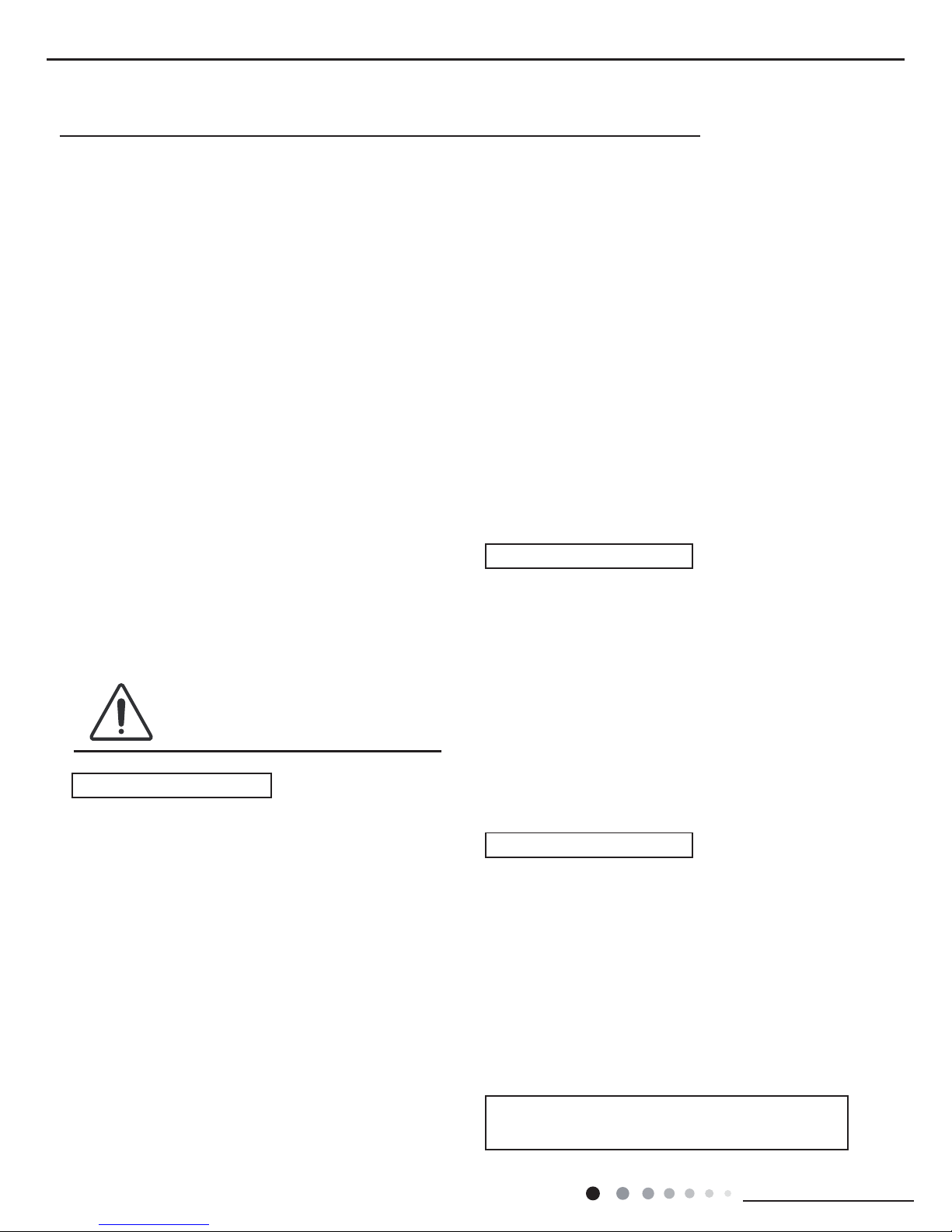
Main Tools for Installation and Maintenance
1. Level meter, measuring tape
4. Electroprobe
7. Electronic leakage detector
10. Pipe pliers, pipe cutter
2. Screw driver
5. Universal meter
8. Vacuum pump
11. Pipe expander, pipe bender
3. Impact drill, drill head, electric drill
6. Torque wrench, open-end wrench, inner
hexagon spanner
9. Pressure meter
12. Soldering appliance, refrigerant container

24
Installation and Maintenance
Service Manual
8. Installation
8.1 Installation Dimension Diagram
Drainage pipe
At least 250cm
At least 15cm
At least 50cm
At least 50cm
At least
30cm
At least 300cm
At least 200cm
Space to the oor
Space to the obstruction
Space to the obstruction
Space to the
obstruction
Space to the ceiling
Space to the obstruction
Space to the obstruction
At least 30cm
At least 15cm
At least 15cm
Space to the wall
Space to the wall
Space to the wall
25
Installation and Maintenance
Service Manual
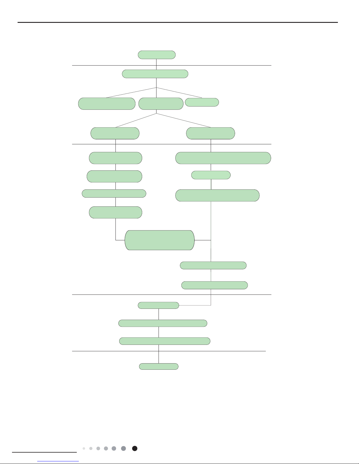
Preparation before installation
Prepare tools
Read the requirements
for electric connection
select installation
location
Select indoor unit
installation location
Install wall-mounting
frame, drill wall holes
Connect pipes of indoor
unit and drainage pipe
Connect wires of indoor unit
Connect wires of outdoor unit
Bind up pipes and
hang the indoor unit
Make the bound pipes pass
through the wall hole and then
connect outdoor unit
Neaten the pipes
Vacuum pumping and leakage detection
Check after installation and test operation
Finish installation
Note: this flow is only for reference; please find the more detailed installation steps in this section.
Select outdoor unit
installation location
Install the support of outdoor unit
(select it according to the actual situation)
Install drainage joint of outdoor unit
(only for cooling and heating unit)
Connect pipes of outdoor unit
Start installation
Fix outdoor unit
Installation procedures
 Loading...