

Gree GWH07AFA-K3NNA1A, GWH09AFB-K3NNA1A, GWH09AFA-K3NNA1A, GWH18AFC-K3NNA1A, GWH24AFD-K3NNA1A Service Manual
...
Change for life
Service Manual
Models:
GWH07AFA-K3NNA1A
GWH09AFA-K3NNA1A
GWH09AFB-K3NNA1A
GWH12AFB-K3NNA1A
GWH12AFC-K3NNA1A
GWH18AFC-K3NNA1A
GWH24AFD-K3NNA1A
(Refrigerant R410A)
GREE ELECTRIC APPLIANCES, INC. OF ZHUHAI

Table of Contents
Service Manual
Part
1. Summary
2. Specications
2.1 Specication Sheet ...........................................................................................................3
2.2 Capacity Curve in Different Outdoor Temperature .........................................................11
2.3 Cooling and Heating Data Sheet in Rated Frequency ...................................................11
: Technical Information
Ⅰ
......................................................................................................................1
..........................................................................................................3
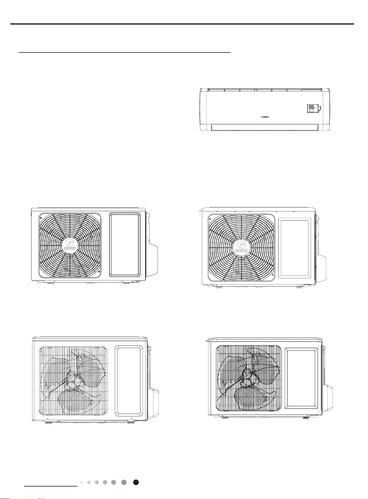
3. Outline Dimension Diagram
3.1 Indoor Unit ......................................................................................................................12
3.2 Outdoor Unit ...................................................................................................................13
4. Refrigerant System Diagram
5. Electrical Part
5.1 Wiring Diagram ...............................................................................................................18
5.2 PCB Printed Diagram .....................................................................................................23
6. Function and Control
.........................................................................................................18
......................................................................................25
.......................................................................1
......................................................................12
....................................................................17
6.1 Remote Controller Introduction ......................................................................................25
6.2 Brief Description of Modes and Functions ......................................................................28
Part
: Installation and Maintenance
Ⅱ
7. Notes for Installation and Maintenance
8. Installation
8.1 Installation Dimension Diagram ......................................................................................36
8.2 Installation Parts-Checking ............................................................................................38
8.3 Selection of Installation Location ....................................................................................38
8.4 Requirements for electric connection .............................................................................38
8.5 Installation of Indoor Unit ................................................................................................38
8.6 Installation of Outdoor unit .............................................................................................41
8.7 Vacuum Pumping and Leak Detection ...........................................................................42
8.8 Check after Installation and Test operation ....................................................................42
9. Maintenance
................................................................................................................36
............................................................................................................43
.................................................33
..........................................33
9.1 Error code .......................................................................................................................43
9.2 Procedure of Troubleshooting ........................................................................................45
9.3 Maintenance method for normal malfunction .................................................................54
Table of Contents

Service Manual
10. Exploded View and Parts List
10.1 Indoor Unit ....................................................................................................................56
10.2 Outdoor Unit .................................................................................................................62
11. Removal Procedure
11.1 Removal Procedure of Indoor Unit ...............................................................................76
11.2 Removal Procedure of Outdoor Unit ............................................................................81
Appendix:
Appendix 1: Reference Sheet of Celsius and Fahrenheit ..................................................105
Appendix 2: Conguration of Connection Pipe ...................................................................105
Appendix 2: Pipe Expanding Method .................................................................................106
Appendix 4: List of Resistance for Temperature Sensor ....................................................107
......................................................................................................................105
.......................................................................................76
..............................................................56
Table of Contents
Service Manual
Part
Ⅰ
: Technical Information
1. Summary
Indoor Unit:
GWH07AFA-K3NNA1A/I
GWH09AFA-K3NNA1A/I
GWH09AFB-K3NNA1A/I
GWH12AFB-K3NNA1A/I
GWH12AFC-K3NNA1A/I
GWH18AFC-K3NNA1A/I
GWH24AFD-K3NNA1A/I
Outdoor Unit:
GWH07ACA-K3NNA5A/O
GWH09ACB-K3NNA5A/O
GWH12QC-K3NNA1A/O
GWH12AAB-K3NNA2A/O GWH18AAC-K3NNA1A/O
Technical Information
1
Service Manual
GWH09AAA-K3NNA1A/O
GWH24AAD-K3NNA1A/O(CA115W14301)
GWH24AAD-K3NNA1A/O(CA115W14300)
Remote Controller:
YAW1F
Models List:
No. Model Product Code Model Product Code Model Product Code
1
GWH07AFA-K3NNA1A
2 CA348000401 CA348N00401
3 GWH09AFB-K3NNA1A CA348000300 GWH09AFB-K3NNA1A/I CA348N00300 GWH09ACB-K3NNA5A/O CA341W00200
4 GWH09AFA-K3NNA1A CA348000800 GWH09AFA-K3NNA1A/I CA348N00800 GWH09AAA-K3NNA1A/O CA115W14400
5 GWH12AFB-K3NNA1A CA348000600 GWH12AFB-K3NNA1A/I CA348N00600 GWH12AAB-K3NNA2A/O CA115W14100
6 GWH12AFC-K3NNA1A CA348000101 GWH12AFC-K3NNA1A/I CA348N00100 GWH12QC-K3NNA1A/O CA419W00101
7 GWH18AFC-K3NNA1A CA348000700 GWH18AFC-K3NNA1A/I CA348N00700 GWH18AAC-K3NNA1A/O CA115W14200
8
GWH24AFD-K3NNA1A
9 CA348000501 CA348N00500 CA115W14301
2
CA348000400
CA348000502
GWH07AFA-K3NNA1A/I
GWH24AFD-K3NNA1A/I
CA348N00400
CA348N00502
GWH07ACA-K3NNA5A/O CA341W00100
GWH24AAD-K3NNA1A/O
CA115W14300
Technical Information
Remote
Controller
YAW1F
Service Manual
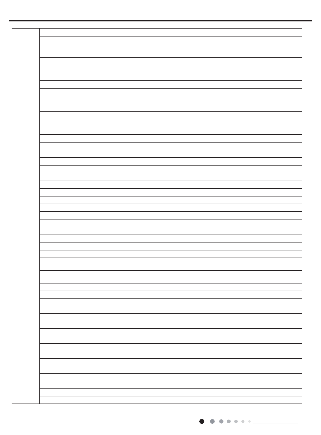
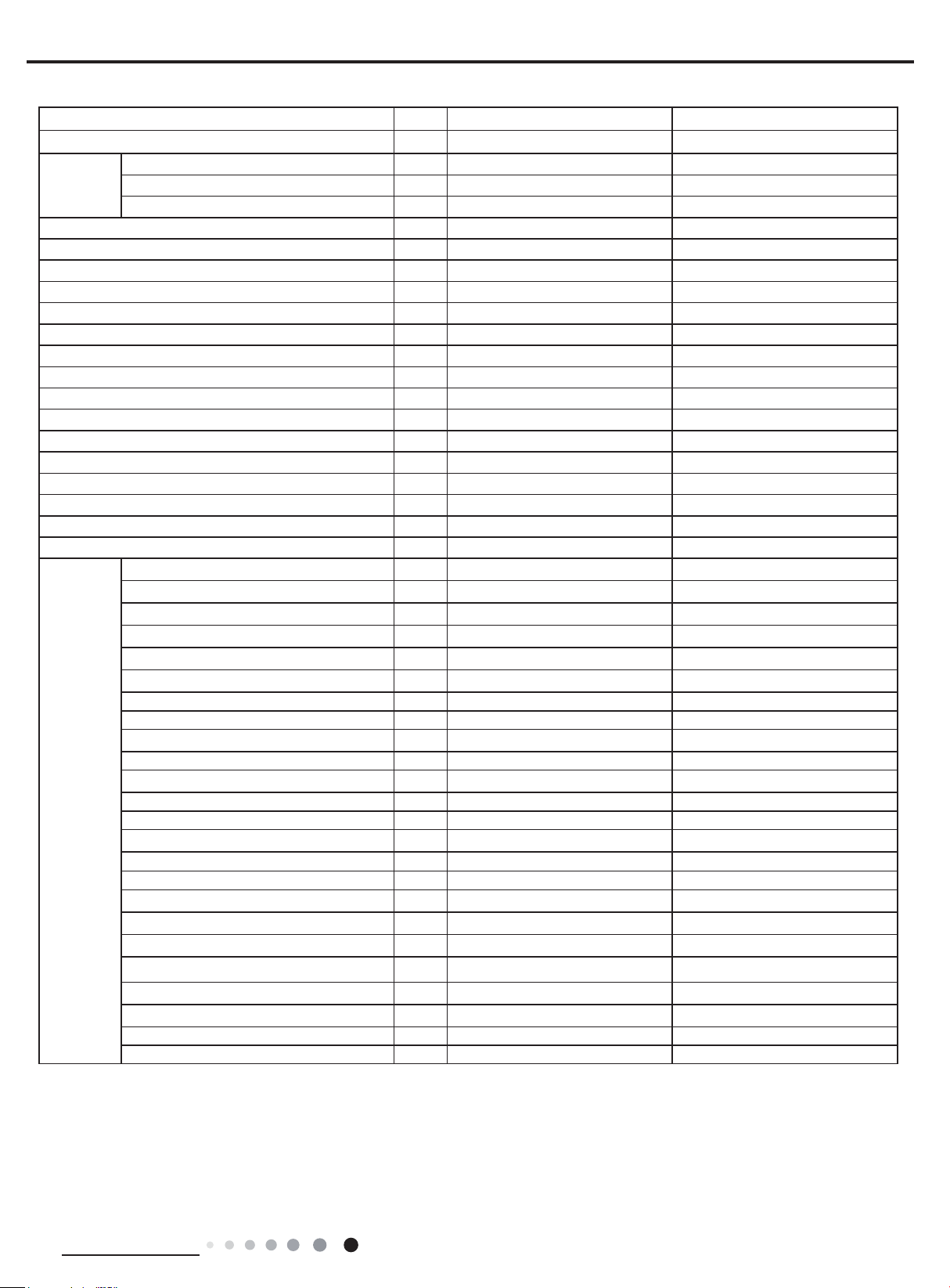
2. Specications
2.1 Specication Sheet
Model GWH07AFA-K3NNA1A GWH09AFB-K3NNA1A
Product Code CA348000400/CA348000401 CA348000300
Power
Supply
Power Supply Mode Indoor Indoor
Cooling Capacity W 2250 2638
Heating Capacity W 2350 2755
Cooling Power Input W 700 821
Heating Power Input W 651 763
Cooling Power Current A 3.5 4.0
Heating Power Current A 3.2 3.5
Rated Input W 1050 1150
Rated Current A 5.5 5.6
Air Flow Volume(SH/H/M/L/SL) m3/h 470/420/370/250/- 570/500/430/300/-
Dehumidifying Volume L/h 0.6 0.8
EER W/W 3.21 3.21
COP W/W 3.61 3.61
SEER W/W / /
HSPF W/W / /
Application Area m
Indoor Unit
Rated Voltage V~ 220-240 220-240
Rated Frequency Hz 50 50
Phases 1 1
2
Model of Indoor Unit GWH07AFA-K3NNA1A/I GWH09AFB-K3NNA1A/I
Product Code of Indoor Unit CA348N00400/CA348N00401 CA348N00300
Fan Type Cross-ow Cross-ow
Diameter Length(DXL) mm Φ93X505 Φ93X505
Fan Motor Cooling Speed(SH/H/M/L/SL) r/min 1300/1200/1100/850/- 1300/1200/1100/850/-
Fan Motor Heating Speed(SH/H/M/L/SL) r/min 1200/1100/1000/900/- 1250/1150/1050/900/-
Output of Fan Motor W 10 20
Fan Motor RLA A 0.15 0.215
Fan Motor Capacitor μF 1 1
Input of Heater W / /
Evaporator Form Aluminum Fin-copper Tube Aluminum Fin-copper Tube
Pipe Diameter mm Φ7.94 Φ7.94
Row-n Gap mm 1-1.2 1-1.2
Coil Length (LXDXW) mm 508X19.05X254 583X19.05X264
Swing Motor Model MP24AN MP24AN
Output of Swing Motor W 1.5 1.5
Fuse A 3.15 3.15
Sound Pressure Level (SH/H/M/L/SL) dB (A) 40/38/35/26/- 40/37/35/27/-
Sound Power Level (SH/H/M/L/SL) dB (A) 50/48/45/36/- 50/47/45/37/-
Dimension (WXHXD) mm 744X256X185 819X256X185
Dimension of Carton Box (LXWXH) mm 788X314X249 863X314X249
Dimension of Package (LXWXH) mm 793X330X260 868X330X260
Net Weight kg 8 8.5
Gross Weight kg 9.5 10
10-16 12-18
Technical Information
3
Outdoor Unit
Connection
Pipe
Service Manual
Model of Outdoor Unit GWH07ACA-K3NNA5A/O GWH09ACB-K3NNA5A/O
Product Code of Outdoor Unit CA341W00100 CA341W00200
Compressor Manufacturer/Trademark
ZHUHAI LANDA COMPRESSOR
CO.,LTD
ZHUHAI LANDA COMPRESSOR
CO.,LTD
Compressor Model QXA-A081A130A QXA-B102C130
Compressor Oil RB68EP/FVC68D/FV50S RB68EP/FV50S
Compressor Type Rotary Rotary
L.R.A. A 15 17
Compressor RLA A 3.25 4
Compressor Power Input W 680 865
Overload Protector UP3-MC0(L
)
UP3-00
Throttling Method Capillary Capillary
Operation Temp
Ambient Temp (Cooling)
Ambient Temp (Heating)
o
C 16~30 16~30
o
C 18~43 18~43
o
C -7~24 -7~24
Condenser Form Aluminum Fin-copper Tube Aluminum Fin-copper Tube
Pipe Diameter mm Φ7.94 Φ7.94
Rows-n Gap mm 1-1.4 1-1.4
Coil Length (LXDXW) mm 658.3X19.05X396 655X19.05X396
Fan Motor Speed rpm 320 320
Output of Fan Motor W 20 20
Fan Motor RLA A 0.25 0.25
Fan Motor Capacitor μF 1.5 1.5
Air Flow Volume of Outdoor Unit m3/h 1200 1200
Fan Type Axial-ow Axial-ow
Fan Diameter mm Φ320 Φ320
Defrosting Method Automatic Defrosting Automatic Defrosting
Climate Type T1 T1
Isolation I I
Moisture Protection IPX4 IPX4
Permissible Excessive Operating Pressure for
the Discharge Side
Permissible Excessive Operating Pressure for
the Suction Side
MPa 4.3 4.3
MPa 2.5 2.5
Sound Pressure Level (H/M/L) dB (A) 49/-/- 48/-/-
Sound Power Level (H/M/L) dB (A) 59/-/- 58/-/-
Dimension (WXHXD) mm 720X428X310 720X428X310
Dimension of Carton Box (LXWXH) mm 765X350X475 765X350X475
Dimension of Package (LXWXH) mm 768X353X490 768X353X490
Net Weight kg 22 25.5
Gross Weight kg 24 27.5
Refrigerant R410A R410A
Refrigerant Charge kg 0.55 0.63
Length m 5 5
Gas Additional Charge g/m 20 15
Outer Diameter Liquid Pipe mm Φ6 Φ6
Outer Diameter Gas Pipe mm Φ9.52 Φ9.52
Max Distance Height m 10 10
Max Distance Length m 15 15
Note: The connection pipe applies metric diameter.
The above data is subject to change without notice; please refer to the nameplate of the unit.
4
Technical Information
Service Manual
Model GWH12AFB-K3NNA1A GWH18AFC-K3NNA1A
Product Code CA348000600 CA348000700
Power
Supply
Rated Voltage V~ 220-240 220-240
Rated Frequency Hz 50 50
Phases 1 1
Power Supply Mode Indoor Indoor
Cooling Capacity W 3250 4800
Heating Capacity W 3400 5000
Cooling Power Input W 1012 1495
Heating Power Input W 941 1500
Cooling Power Current A 4.32 6.81
Heating Power Current A 4.40 6.72
Rated Input W 1230 2150
Rated Current A 6.3 10.96
Air Flow Volume(SH/H/M/L/SL) m3/h 550/500/430/330/- 650/560/480/350/-
Dehumidifying Volume L/h 1.2 1.8
EER W/W 3.21 3.21
COP W/W 3.61 3.61
SEER W/W / /
HSPF W/W / /
Application Area m
2
15-22 21-31
Model of Indoor Unit GWH12AFB-K3NNA1A/I GWH18AFC-K3NNA1A/I
Product Code of Indoor Unit CA348N00600 CA348N00700
Fan Type Cross-ow Cross-ow
Diameter Length(DXL) mm Φ93X580 Φ98X633
Fan Motor Cooling Speed(SH/H/M/L/SL) r/min 1350/1200/1100/850/- 1350/1200/1050/950/-
Fan Motor Heating Speed(SH/H/M/L/SL) r/min 1350/1200/1100/900/- 1300/1150/1000/900/-
Output of Fan Motor W 20 20
Fan Motor RLA A 0.215 0.31
Fan Motor Capacitor μF 1 1.5
Input of Heater W / /
Evaporator Form Aluminum Fin-copper Tube Aluminum Fin-copper Tube
Pipe Diameter mm Φ7.94 Φ7
Indoor Unit
Row-n Gap mm 1-1.2 2-1.4
Coil Length (LXDXW) mm 583X19.05X264 715X25.4X304.8
Swing Motor Model MP24AN MP24HF
Output of Swing Motor W 1.5 1.5
Fuse A 3.15 3.15
Sound Pressure Level (SH/H/M/L/SL) dB (A) 42/39/36/33/- 42/38/34/31/-
Sound Power Level (SH/H/M/L/SL) dB (A) 52/49/46/43/- 52/48/44/41/-
Dimension (WXHXD) mm 819X256X185 889X294X212
Dimension of Carton Box (LXWXH) mm 863X314X249 935X349X273
Dimension of Package (LXWXH) mm 868X330X260 940X365X284
Net Weight kg 8.5 11
Gross Weight kg 10 13
Technical Information
5
Model of Outdoor Unit GWH12AAB-K3NNA2A/O GWH18AAC-K3NNA1A/O
Product Code of Outdoor Unit CA115W14100 CA115W14200
Compressor Manufacturer/Trademark
ZHUHAI LANDA
COMPRESSOR CO., LTD
Compressor Model QXA-B120C150A QXA-D19F030
Compressor Oil RB68EP ATMOS-RB68EP or equivalent
Compressor Type Rotary Rotary
L.R.A. A 26 38.00
Compressor RLA A 4.4 7.10
Compressor Power Input W 970 1540
Overload Protector INTERNAL (UP3-02) UP3-A6
Throttling Method Capillary Capillary
Operation Temp
Ambient Temp (Cooling)
Ambient Temp (Heating)
o
C 16~30 16~30
o
C 18~43 18~48
o
C -7~24 -7~24
Condenser Form Aluminum Fin-copper Tube Aluminum Fin-copper Tube
Pipe Diameter mm Φ7.94 Φ7.94
Rows-n Gap mm 1-1.4 2-1.4
Coil Length (LXDXW) mm 697X19.05X506 735X38.1X508
Fan Motor Speed rpm 850 850
Output of Fan Motor W 35 35
Outdoor Unit
Fan Motor RLA A 0.33 0.33
Fan Motor Capacitor μF 2.5 2.5
Air Flow Volume of Outdoor Unit m3/h 1600 1800
Fan Type Axial-ow Axial-ow
Fan Diameter mm Φ394 Φ394.5
Defrosting Method Automatic Defrosting Automatic Defrosting
Climate Type T1 T1
Isolation I I
Moisture Protection IPX4 IPX4
Permissible Excessive Operating Pressure for
the Discharge Side
Permissible Excessive Operating Pressure for
the Suction Side
MPa 4.3 4.3
MPa 2.5 2.5
Sound Pressure Level (H/M/L) dB (A) 52/-/- 56/-/-
Sound Power Level (H/M/L) dB (A) 62/-/- 66/-/-
Dimension (WXHXD) mm 782X540X320 848X540X320
Dimension of Carton Box (LXWXH) mm 820X355X580 878X360X580
Dimension of Package (LXWXH) mm 823X358X595 881X363X595
Net Weight kg 30 39
Gross Weight kg 32.5 41.5
Refrigerant R410A R410A
Refrigerant Charge kg 0.72 1.26
Length m 5 5
Gas Additional Charge g/m 15 15
Outer Diameter Liquid Pipe mm Φ6 Φ6
Connection
Pipe
Outer Diameter Gas Pipe mm Φ12 Φ12
Max Distance Height m 10 10
Max Distance Length m 15 25
Note: The connection pipe applies metric diameter.
The above data is subject to change without notice; please refer to the nameplate of the unit.
Service Manual
ZHUHAI LANDA
COMPRESSOR CO., LTD
6
Technical Information
Service Manual
Model GWH12AFC-K3NNA1A GWH09AFA-K3NNA1A
Product Code CA348000101 CA348000800
Rated Voltage V~ 220-240 220-240
Power
Supply
Rated Frequency Hz 50 50
Phases 1 1
Power Supply Mode Indoor Indoor
Cooling Capacity W 3550 2550
Heating Capacity W 3700 2650
Cooling Power Input W 1106 794
Heating Power Input W 1025 734
Cooling Power Current A 4.9 3.7
Heating Power Current A 4.56 3.3
Rated Input W 1500 1120
Rated Current A 7.8 6.2
Air Flow Volume(SH/H/M/L/SL) m3/h 630/540/460/330/- 470/420/370/250/-
Dehumidifying Volume L/h 1.4 0.8
EER W/W 3.21 3.21
COP W/W 3.61 3.61
SEER W/W / /
HSPF W/W / /
Application Area m
2
16-24 12-18
Model of Indoor Unit GWH12AFC-K3NNA1A/I GWH09AFA-K3NNA1A/I
Product Code of Indoor Unit CA348N00100 CA348N00800
Fan Type Cross-ow Cross-ow
Diameter Length(DXL) mm Φ98X633.5 Φ93X505
Fan Motor Cooling Speed(SH/H/M/L/SL) r/min 1350/1200/1050/850/- 1300/1200/1100/850/-
Fan Motor Heating Speed(SH/H/M/L/SL) r/min 1300/1150/1000/900/- 1200/1100/1000/900/-
Output of Fan Motor W 20 10
Fan Motor RLA A 0.31 0.15
Fan Motor Capacitor μF 1.5 1
Input of Heater W / /
Evaporator Form Aluminum Fin-copper Tube Aluminum Fin-copper Tube
Indoor Unit
Pipe Diameter mm Φ5 Φ7.94
Row-n Gap mm 2-1.4 1-1.2
Coil Length (LXDXW) mm 635X22.8X306.3 508X19.05X254
Swing Motor Model MP24HF MP24AN
Output of Swing Motor W 1.5 1.5
Fuse A 3.15 3.15
Sound Pressure Level (SH/H/M/L/SL) dB (A) 41/38/33/29/- 40/38/35/26/-
Sound Power Level (SH/H/M/L/SL) dB (A) 51/47/43/39/- 50/48/45/36/-
Dimension (WXHXD) mm 889X294X211 744X256X185
Dimension of Carton Box (LXWXH) mm 943X349X278 788X314X249
Dimension of Package (LXWXH) mm 948X365X289 793X330X260
Net Weight kg 11 8.0
Gross Weight kg 13 9.5
Technical Information
7
Model of Outdoor Unit GWH12QC-K3NNA1A/O GWH09AAA-K3NNA1A/O
Product Code of Outdoor Unit CA419W00101 CA115W14400
Compressor Manufacturer/Trademark
ZHUHAI LANDA COMPRESSOR
CO., LTD
Compressor Model QXA-C133B030gA QXA-M094T130
Compressor Oil RB68EP/FVC 68D RB68EP or equivalent
Compressor Type Rotary Rotary
L.R.A. A 25 18
Compressor RLA A 5.17 3.6
Compressor Power Input W 1120 772.7
Overload Protector Internal UP3-MC1
Throttling Method Capillary Capillary
Operation Temp
Ambient Temp (Cooling)
Ambient Temp (Heating)
o
C 16~30 16~30
o
C 18~43 18~43
o
C -7~24 -7~24
Condenser Form Aluminum Fin-copper Tube Aluminum Fin-copper Tube
Pipe Diameter mm Φ7.94 Φ7.94
Rows-n Gap mm 1-1.4 1-1.4
Coil Length (LXDXW) mm 757X19.05X506 658.3X19.05X396
Fan Motor Speed rpm 850 320
Output of Fan Motor W 30 20
Outdoor Unit
Fan Motor RLA A 0.45 0.25
Fan Motor Capacitor μF 2 1.5
Air Flow Volume of Outdoor Unit m3/h 1800 1200
Fan Type Axial-ow Axial-ow
Fan Diameter mm Φ400 Φ320
Defrosting Method Automatic Defrosting Automatic Defrosting
Climate Type T1 T1
Isolation I I
Moisture Protection IPX4 IPX4
Permissible Excessive Operating Pressure for
the Discharge Side
Permissible Excessive Operating Pressure for
the Suction Side
MPa 4.3 4.3
MPa 2.5 2.5
Sound Pressure Level (H/M/L) dB (A) 52/-/- 49/-/-
Sound Power Level (H/M/L) dB (A) 62/-/- 59/-/-
Dimension (WXHXD) mm 848X540X320 720X428X310
Dimension of Carton Box (LXWXH) mm 878X360X580 765X350X475
Dimension of Package (LXWXH) mm 881X363X595 768X353X490
Net Weight kg 33 24.5
Gross Weight kg 35.5 26.5
Refrigerant R410A R410A
Refrigerant Charge kg 0.8 0.56
Length m 5 5
Gas Additional Charge g/m 20 20
Outer Diameter Liquid Pipe mm Φ6 Φ6
Connection
Pipe
Outer Diameter Gas Pipe mm Φ12 Φ9.52
Max Distance Height m 10 10
Max Distance Length m 20 15
Note: The connection pipe applies metric diameter.
The above data is subject to change without notice; please refer to the nameplate of the unit.
Service Manual
ZHUHAI LANDA COMPRESSOR
CO.,LTD
8
Technical Information
Service Manual
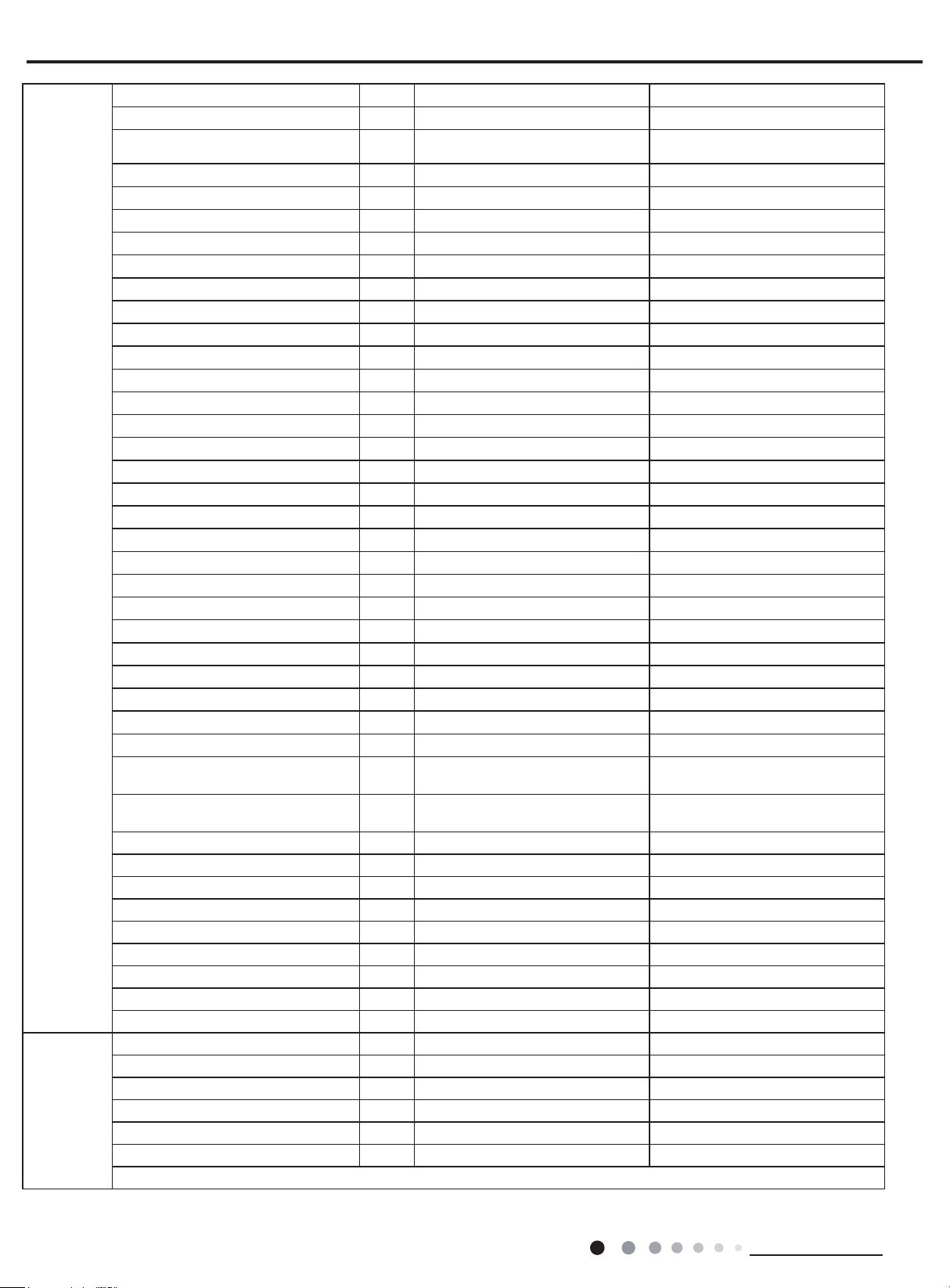
Model GWH24AFD-K3NNA1A GWH24AFD-K3NNA1A
Product Code CA348000502 CA348000501
Rated Voltage V~ 220-240 220-240
Power
Supply
Rated Frequency Hz 50 50
Phases 1 1
Power Supply Mode Indoor Indoor
Cooling Capacity W 6150 6150
Heating Capacity W 6700 6700
Cooling Power Input W 1915 1915
Heating Power Input W 1856 1856
Cooling Power Current A 8.49 8.49
Heating Power Current A 8.23 8.23
Rated Input W 2700 2700
Rated Current A 13.88 13.88
Air Flow Volume(SH/H/M/L/SL) m3/h 900/800/700/600/- 900/800/700/600/-
Dehumidifying Volume L/h 1.8 1.8
EER W/W 3.21 3.21
COP W/W 3.61 3.61
SEER W/W / /
HSPF W/W / /
Application Area m
2
23-34 23-34
Model of Indoor Unit GWH24AFD-K3NNA1A/I GWH24AFD-K3NNA1A/I
Product Code of Indoor Unit CA348N00502 CA348N00500
Fan Type Cross-ow Cross-ow
Diameter Length(DXL) mm Φ106X706 Φ106X706
Fan Motor Cooling Speed(SH/H/M/L/SL) r/min 1350/1200/1050/900/- 1350/1200/1050/900/-
Fan Motor Heating Speed(SH/H/M/L/SL) r/min 1350/1200/1100/900/- 1350/1200/1100/900/-
Output of Fan Motor W 35 35
Fan Motor RLA A 0.35 0.35
Fan Motor Capacitor μF 2.5 2.5
Input of Heater W / /
Evaporator Form Aluminum Fin-copper Tube Aluminum Fin-copper Tube
Indoor Unit
Pipe Diameter mm Φ7 Φ7
Row-n Gap mm 2-1.4 2-1.4
Coil Length (LXDXW) mm 715X25.4X304.8 715X25.4X304.8
Swing Motor Model MP35CP MP35CP
Output of Swing Motor W 2.5 2.5
Fuse A 3.15 3.15
Sound Pressure Level (SH/H/M/L/SL) dB (A) 49/45/41/37/- 49/45/41/37/-
Sound Power Level (SH/H/M/L/SL) dB (A) 59/55/51/47/- 59/55/51/47/-
Dimension (WXHXD) mm 1017X304X221 1017X304X221
Dimension of Carton Box (LXWXH) mm 1077X375X300 1077X375X300
Dimension of Package (LXWXH) mm 1080X378X315 1080X378X315
Net Weight kg 14 14
Gross Weight kg 17 17
Technical Information
9
Outdoor Unit
Connection
Pipe
Service Manual
Model of Outdoor Unit GWH24AAD-K3NNA1A/O GWH24AAD-K3NNA1A/O
Product Code of Outdoor Unit CA115W14300 CA115W14301
Compressor Manufacturer/Trademark
ZHUHAI LANDA COMPRESSOR
CO.,LTD
ZHUHAI LANDA COMPRESSOR
CO.,LTD
Compressor Model QXA-F232F050 QXA-F232F050
Compressor Oil RB68EP RB68EP
Compressor Type Rotary Rotary
L.R.A. A 40 40
Compressor RLA A 8.4 8.4
Compressor Power Input W 1930 1930
Overload Protector UP3-27 UP3-27
Throttling Method Capillary Capillary
Operation Temp
Ambient Temp (Cooling)
Ambient Temp (Heating)
o
C 16~30 16~30
o
C 18~48 18~48
o
C -7~24 -7~24
Condenser Form Aluminum Fin-copper Tube Aluminum Fin-copper Tube
Pipe Diameter mm Φ7 Φ7
Rows-n Gap mm 1-1.4 1-1.4
Coil Length (LXDXW) mm 613X38.1X660 613X38.1X660
Fan Motor Speed rpm 780 780
Output of Fan Motor W 68 68
Fan Motor RLA A 0.75 0.75
Fan Motor Capacitor μF 2.5 2.5
Air Flow Volume of Outdoor Unit m3/h 2800 2800
Fan Type Axial-ow Axial-ow
Fan Diameter mm Φ460 Φ460
Defrosting Method Automatic Defrosting Automatic Defrosting
Climate Type T1 T1
Isolation I I
Moisture Protection IPX4 IPX4
Permissible Excessive Operating
Pressure for the Discharge Side
Permissible Excessive Operating
Pressure for the Suction Side
MPa 4.3 4.3
MPa 2.5 2.5
Sound Pressure Level (H/M/L) dB (A) 56/-/- 56/-/-
Sound Power Level (H/M/L) dB (A) 66/-/- 66/-/-
Dimension (WXHXD) mm 931X680X378 931X680X378
Dimension of Carton Box (LXWXH) mm 994X428X725 994X428X725
Dimension of Package (LXWXH) mm 997X431X740 997X431X740
Net Weight kg 50 50
Gross Weight kg 54 54
Refrigerant R410A R410A
Refrigerant Charge kg 1.45 1.45
Length m 5 5
Gas Additional Charge g/m 15 15
Outer Diameter Liquid Pipe mm Φ6 Φ6
Outer Diameter Gas Pipe mm Φ12 Φ12
Max Distance Height m 10 10
Max Distance Length m 25 25
Note: The connection pipe applies metric diameter.
The above data is subject to change without notice; please refer to the nameplate of the unit.
10
Technical Information
Service Manual
)
%
(
o i t a r y t i c a p a
C
24
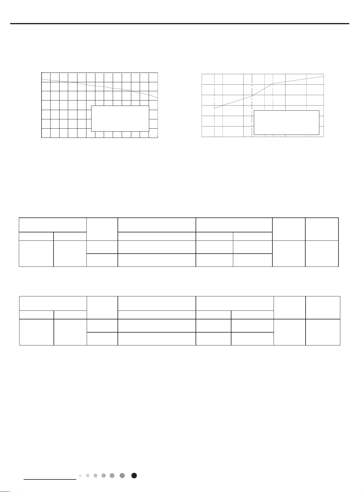
2.2 Capacity Curve in Different Outdoor Temperature
Cooling Heating
110
100
90
80
70
60
50
40
Condition
Indoor:DB27
Indoor air flow: Super High
Pipe length:5m
°C
WB19
°C
32 33 34 35 36 37 38 39 40 41 42 43 44 45
Outdoor temp.( ) Outdoor temp.( )
°C
120
)%(oitar yticapaC
100
80
60
40
20
0
-10510
2.3 Cooling and Heating Data Sheet in Rated Frequency
Cooling
Rated cooling condition(°C)
(DB/WB)
Indoor Outdoor P (MPa) T1 (°C) T2 (°C)
27/19 35/24
Model
07/09K 0.85~1.0
12/18/24K 0.9~1.1
Pressure of gas pipe connecting
indoor and outdoor unit
Inlet and outlet pipe temperature
of heat exchanger
in:8~11
out:11~14
in:10~14
out:11~14
Condition Heating
Indoor:DB20
Indoor air flow: Super High
Pipe length:5m
°C
Fan speed of
indoor unit
in:75~85
out:37~43
in:69~74
out:38~45
Super High High
°C
157-7 -5 02
Fan speed of
outdoor unit
Heating
Rated heatling condition(°C)
(DB/WB)
Indoor Outdoor P (MPa) T1 (°C) T2 (°C)
20/- 7/6
Instruction:
T1: Inlet and outlet pipe temperature of evaporator
T2: Inlet and outlet pipe temperature of condenser
P: Pressure at the side of big valve
Connection pipe length: 5m.
Model
07/09K 3.5~3.8
12/18/24K 2.8~3.2
Pressure of gas pipe connecting
indoor and outdoor unit
Inlet and outlet pipe temperature
of heat exchanger
in:75~85
out:37~43
in:55~65
out:25~32
in:1~3
out:2~5
in:1~3
out:2~5
Fan speed of
indoor unit
Super High High
Fan speed of
outdoor unit
Technical Information
11
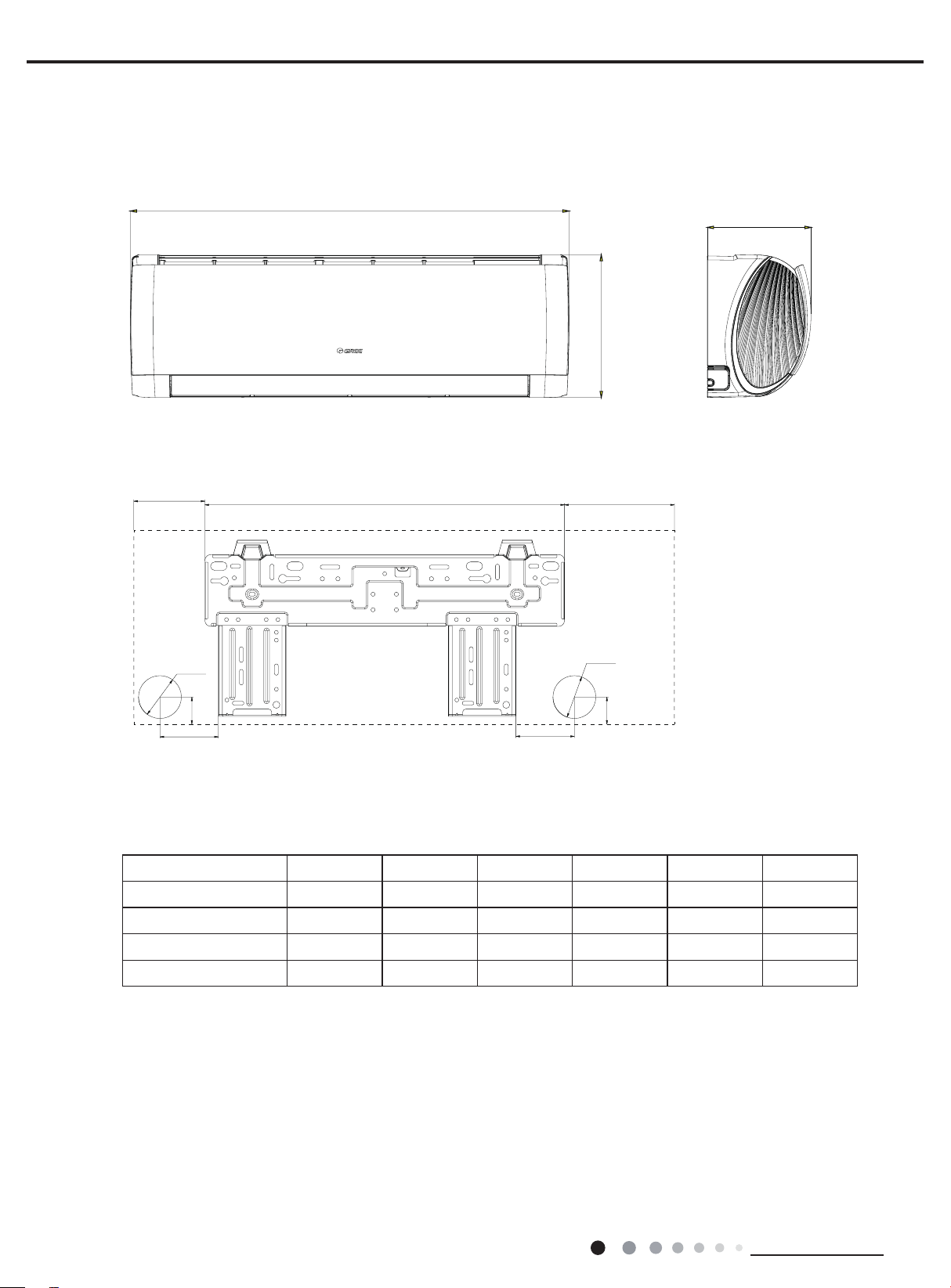
3. Outline Dimension Diagram
75
W
3.1 Indoor Unit
Service Manual
D
H
W1
Φ55
35
75
Models W H D W1 W2 W3
AFA 744 256 185 116 462 166
AFB 819 256 185 154 462 203
AFC 889 294 211 201 542 146
AFD 1017 304 221 127.5 685 204.5
W3W2
Φ55
35
Unit:mm
12
Technical Information
Service Manual
255
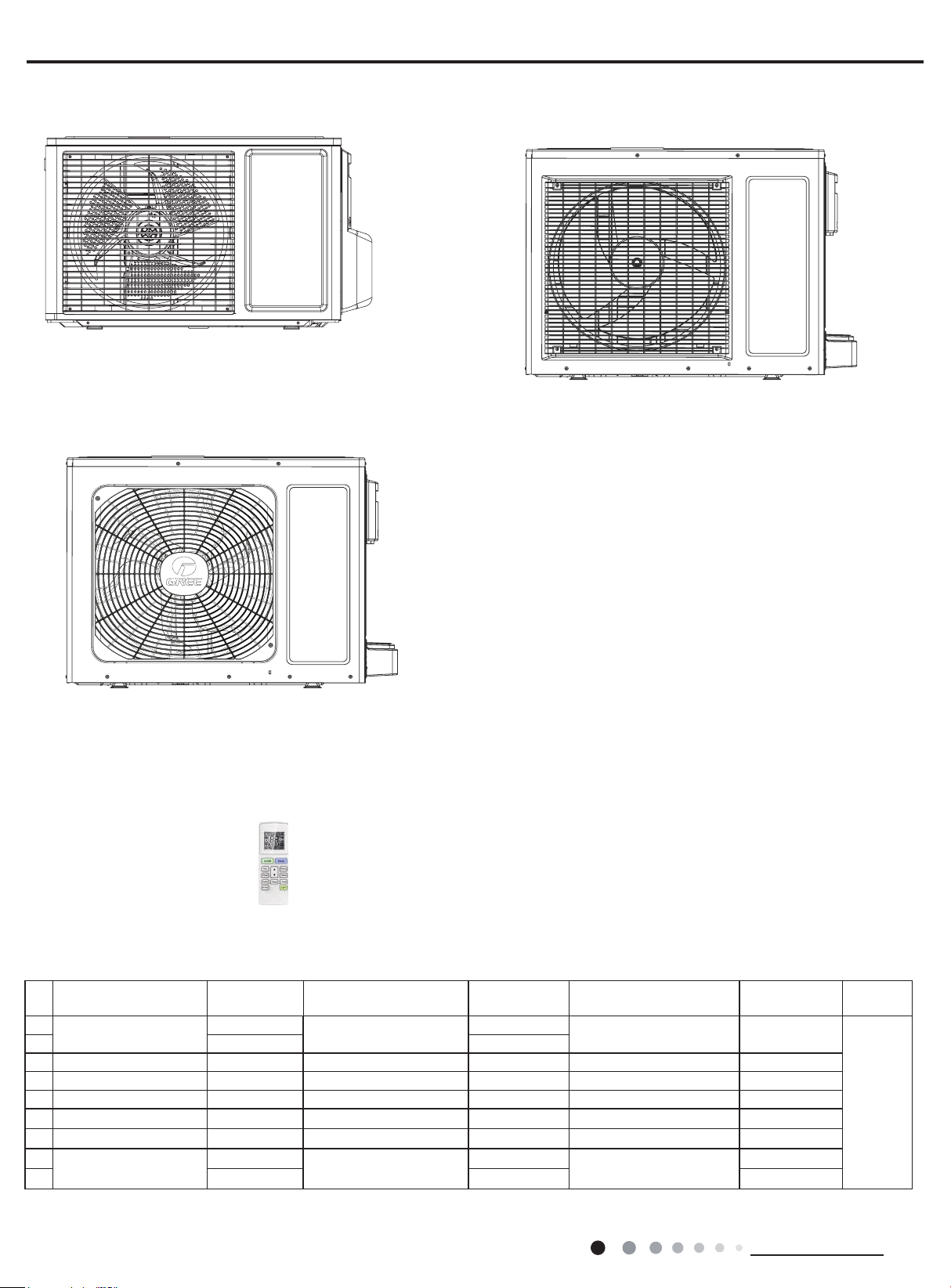
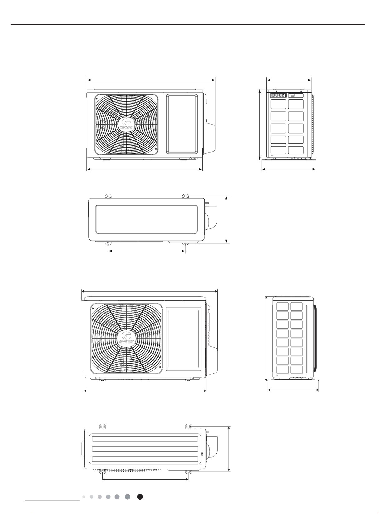
3.2 Outdoor Unit
GWH07ACA-K3NNA5A/O
GWH09ACB-K3NNA5A/O
720
824
GWH12QC-K3NNA1A/O
660
440
848
310
682
Unit:mm
540
Technical Information
320
763
268
Unit:mm
510
13
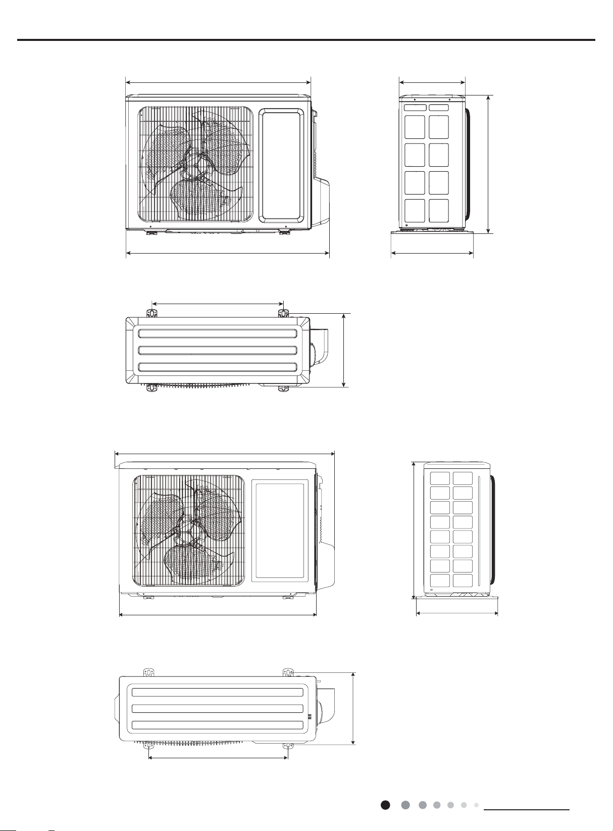
GWH12AAB-K3NNA2A/O
712
257
Service Manual
540
GWH18AAC-K3NNA1A/O
848
782
510
320
286
Unit:mm
540
14
320
763
268
Unit:mm
510
Technical Information
Service Manual
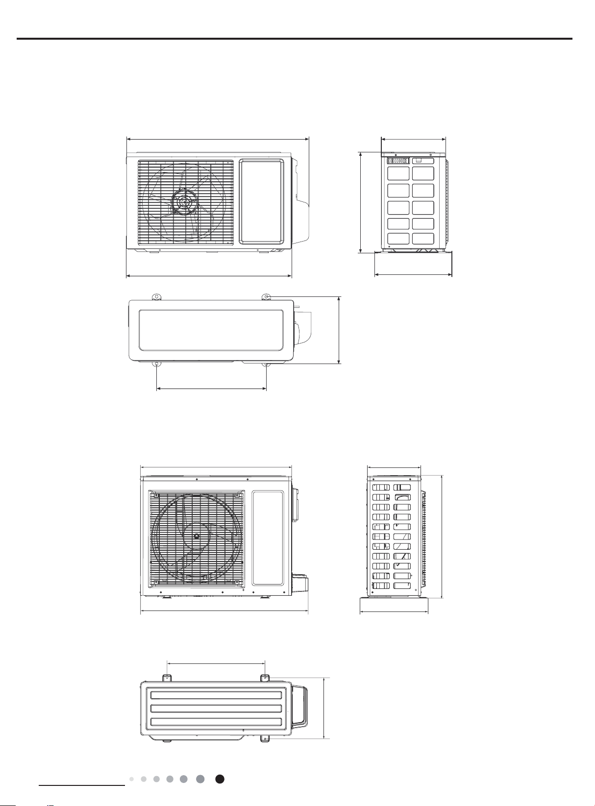
847
300
GWH09AAA-K3NNA1A/O
660
440
720
255
428
310
286
Unit:mm
GWH24AAD-K3NNA1A/O(CA115W14300)
931
549
680
378
843
Technical Information
Unit:mm
15
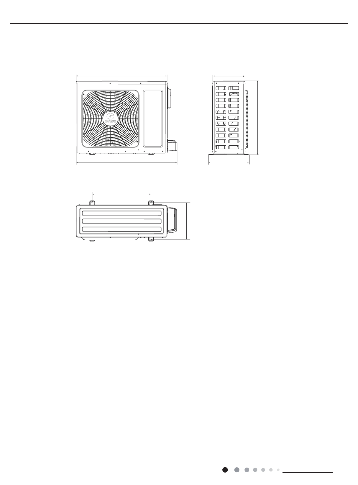
GWH24AAD-K3NNA1A/O(CA115W14301)
847
300
Service Manual
680
931
549
378
843
Unit:mm
16
Technical Information
Service Manual
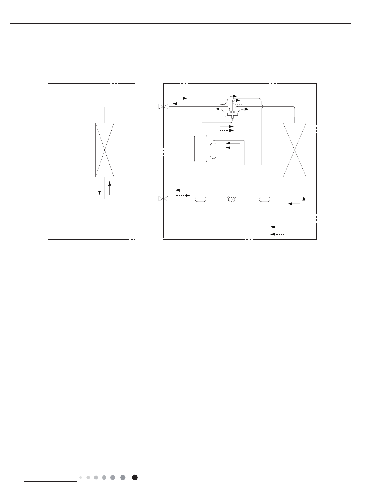
Indoor unit
Outdoor unit
Accumlator
COOLING
Discharge
Suction
Heat
exchanger
(evaporator)
Heat
exchanger
(condenser)
Valve
Valve
Liquid pipe
side
Gas pipe
side
Compressor
Strainer
Capillary
4. Refrigerant System Diagram
Cooling and heating model
Indoor unit
Heat
exchanger
(evaporator)
Connection pipe specication:
Liquid pipe:1/4" (6mm)
Gas pipe:3/8" (9.52mm) 09K
Gas pipe:1/2" (12mm)12/18/24K
Gas pipe
side
Valve
Liquid pipe
side
Valve
Discharge
Compressor
Strainer
Suction
Accumlator
Outdoor unit
4-Way valve
Heat
exchanger
(condenser)
StrainerCapillary
COOLING
HEATING
Technical Information
17
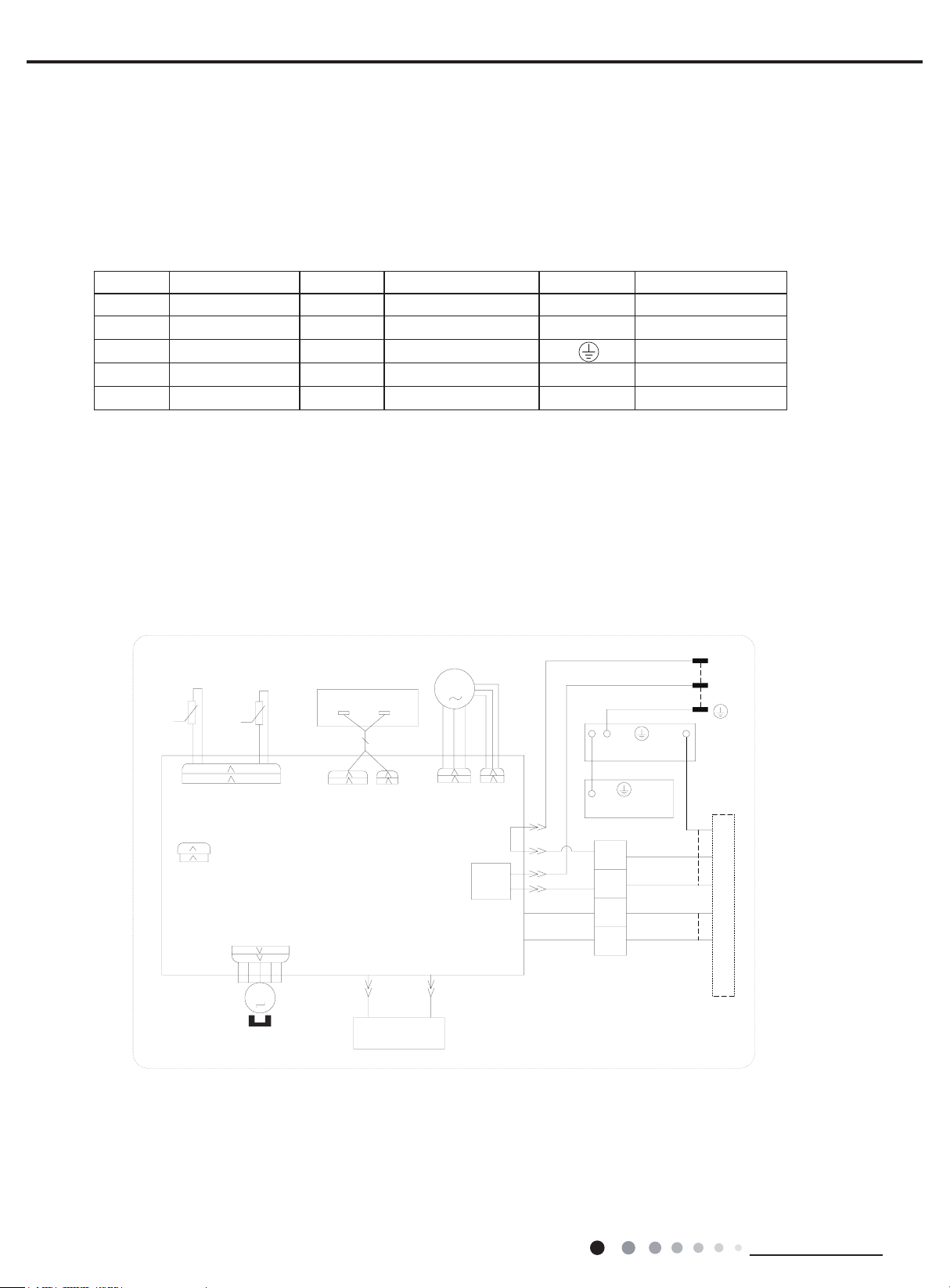
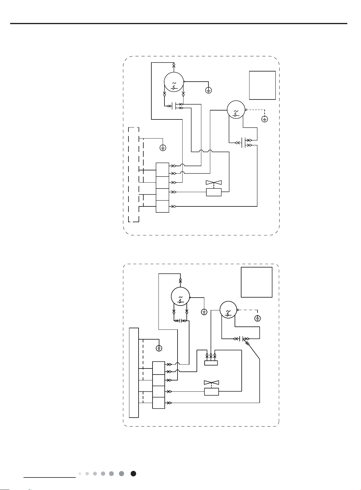
5. Electrical Part
5.1 Wiring Diagram
●Instruction
Symbol Symbol Color Symbol Symbol Color Symbol Name
WH White GN Green CAP Jumper cap
YE Yellow BN Brown COMP Compressor
RD Red BU Blue Grounding wire
YEGN Yellow/Green BK Black / /
VT Violet OG Orange / /
Note: Jumper cap is used to determine fan speed and the swing angle of horizontal lover for this model.
Service Manual
● Indoor Unit
GWH07AFA-K3NNA1A/I(CA348N00400) GWH09AFB-K3NNA1A/I GWH12AFC-K3NNA1A/I
78%(7(03
6(1625
57
76(1625
&$3
-803
52207(03
6(1625
57
5(&(,9(5$1'
',63/$<%2$5'
$3
',63/$<
',63
',63
$3
35,17('&,5&8,7%2$5'
..
6:,1*8'
+($/7+1
%8
0
67(33,1*
02725
+($/7+/
5'
&2/'3/$60$
*(1(5$725
)$102725
0
3*)
3*
$&/
&203
:$<
2)$1
1
%8:+
%1%.
<(*1*1
($57+3/$7(
<(*1
(9$325$725
;7
%8
1
%.
97
2*
7(50,1$/
%/2&.
32:(5
3(
3(
&11(&7,1*
<(*1
%8
%.
97
2*
&$%/(
63632201
1
/
287'22581,7
18
Technical Information
Service Manual
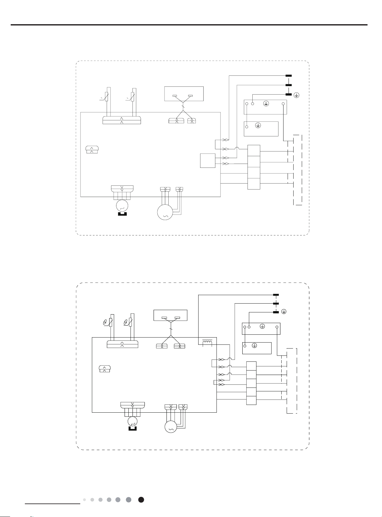
GWH09AFA-K3NNA1A/I GWH12AFB-K3NNA1A/I GWH18AFC-K3NNA1A/I GWH07AFA-K3NNA1A/I(CA348N00401)
TUBE TEMP.
SENSOR
0
RT1
CAP
JUMP
ROOM TEMP.
SENSOR
0
RECEIVER AND
DISPLAY BOARD
AP1
DISPLAY
RT2
T-SENSOR
DISP1
AP2
PRINTED CIRCUIT BOARD
K1(K3)
SWING-UD
M2
STEPPING
MOTOR
PGF
PG
M1
FAN MOTOR
DISP2
N1
AC-L
COMP
4WAY
OFAN
BU(WH)
BN(BK)
YEGN(GN)
EARTH-PLATE
YEGN
EVAPORATOR
XT
BU
N(1)
BK
2
VT
4
OG
5
TERMINAL
BLOCK
POWER
PE
PE
BU
BK
VT
OG
C0NNECTING
CABLE
6363220101
N
L
YEGN
OUTDOOR UNIT
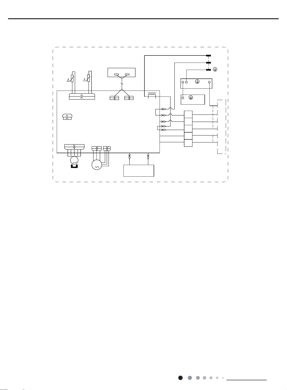
GWH24AFD-K3NNA1A/I (CA348N00502)
78%(
7(03
6(1625
57
&$3
-803
5220
7(03
6(1625
57
76(1625
35,17('&,5&8,7%2$5'
6:,1*
6:,1*8'
0
67(33,1*
02725
5(&(,9(5$1'
',63/$<%2$5'
$3
',63
$3
)$102725
',63/$<
',63
3*)
3*
0
/
1
&203
/$&/
:$<
2)$1
<(*1*1
($57+3/$7(
<(*1
(9$325$725
;7
%8
1
%.
%1
97
2*
7(50,1$/
%/2&.
%1%.
%8:+
32:(5
3(
3(
%8
%.
%1
97
2*
&211(&7,1*
&$%/(
6363243702
/
1
<(*1
287'22581,7
Technical Information
19
GWH24AFD-K3NNA1A/I (CA348N00500)
Service Manual
78%(
7(03
6(1625
57
76(1625
&$3
-803
6:,1*
6:,1*8'
0
67(33,1*
02725
5220
7(03
6(1625
5(&(,9(5$1'
',63/$<%2$5'
',63/$<
$3
57
',63
$3
35,17('&,5&8,7%2$5'
3*)
3*
+($/7+/
0
)$102725
',63
/$&/
+($/7+1
%85'
&2/'3/$60$
*(1(5$725
/
1
&203
:$<
2)$1
<(*1*1
($57+3/$7(
<(*1
(9$325$725
;7
%8
1
%.
%1
97
2*
7(50,1$/
%/2&.
%1%.
%8:+
3(
&211(&7,1*
63632437
32:(5
3(
%8
%.
%1
97
2*
&$%/(
/
1
<(*1
287'22581,7
20
Technical Information
Service Manual
● Outdoor Unit
GWH07ACA-K3NNA5A/O
GWH09ACB-K3NNA5A/O
GWH09AAA-K3NNA1A/O
GWH12QC-K3NNA1A/O
GWH18AAC-K3NNA1A/O
%.
<(
&
&203
3(
&203
6
&
<(*1
50
%8
3(
%8%.
)$1
02725
3(
0
127(
0RWRUJURXQG
RQO\DSSOLHV
WRWKHLURQ
VKHOOPRWRU
<(*1
&$3
5'
%1
3(
GWH12AAB-K3NNA2A/O
<(*1
3(
;7
%8
1
%.
97
2*
,1'22581,7
7(50,1$/
%/2&.
&
&203
%.
<(*1
3(
<(
6
&
&$3
%8
97
2*
&203
3(
50
%8
%8%.
<9
:$<
<(*1
3(
9$/9(
)$1
02725
0
5'
&
&$3
97
61413350
127(
0RWRUJURXQG
RQO\DSSOLHV
WRWKHLURQ
VKHOOPRWRU
<(*1
3(
%1
&
&$3
3(
Technical Information
;7
%8
1
%.
97
2*
,1'22581,7
7(50,1$/
%/2&.
%8
%8
97
2*
7(50,1$/
%/2&.
<9
;7
:$<
9$/9(
97
636361501
21
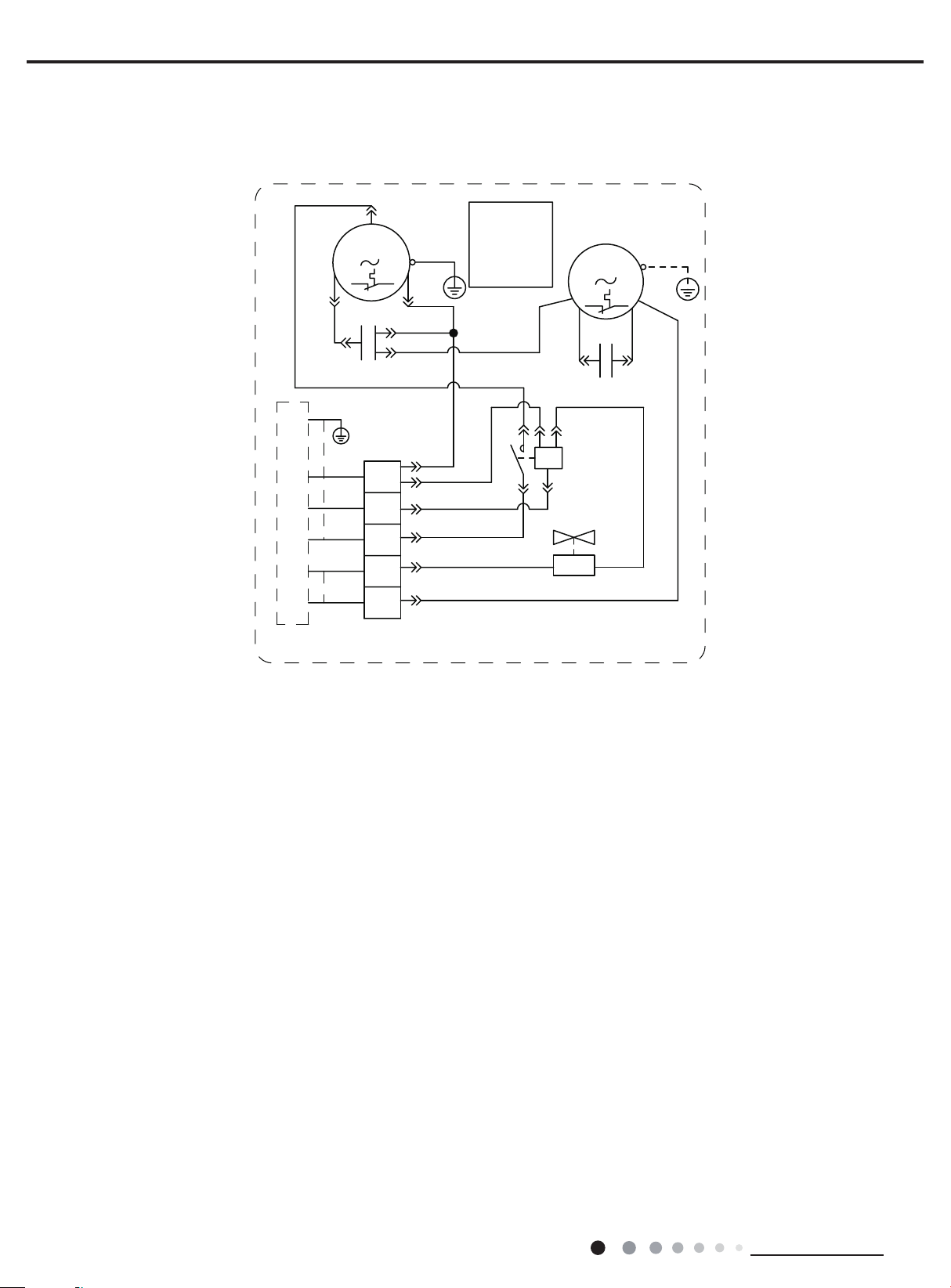
GWH24AAD-K3NNA1A/O(CA115W14300/CA115W14301)
Service Manual
&
&203
6
%.
<(
<(*1
3(
%8
%.
%1
97
,1'22581,7
2*
7(50,1$/
&
&$3
;7
1
%/2&.
&203
<(*1
50
%8
%8
%8
%.
%1
97
2*:+
127(0RWRU
JURXQGRQO\
DSSOLHVWR
WKHLURQ
VKHOOPRWRU
3(
%8
-
%.
/
%8
7
)$102725
0
5'
%1
.0
:$<9$/9(
&
&$3
$
$
$&&217$&725
<9
6363344001
<(*1
3(
%1
97
These wiring diagrams are subject to change without notice; please refer to the one supplied with the unit.
22
Technical Information
Service Manual
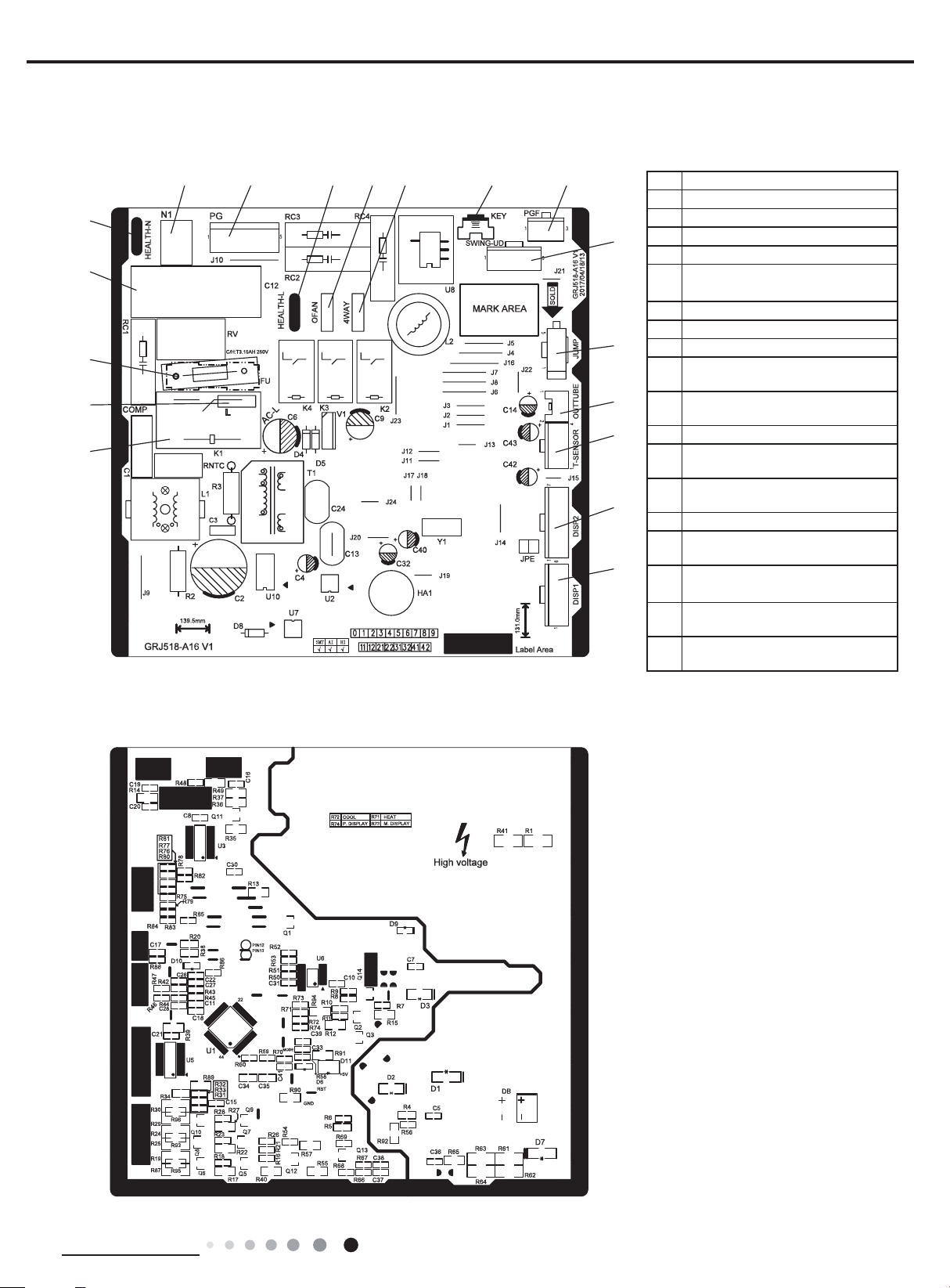
5.2 PCB Printed Diagram
07/09K GWH12AFB-K3NNA1A/I
● Top view
67
5
4
3
2
1
89
10
11 12
No. Name
1 Wiring terminal of compressor
2 Terminal of live wire
3 Fuse
13
4 Fan capacitor
Neutral wire terminal of cold
5
plasma
6 Terminal of neutral wire
7 Wiring terminal of PG motor
14
8 Live wire terminal for cold plasma
Wiring terminal of outdoor fan
9
(heat pump unit)
15
16
17
Wiring terminal of 4-way valve
10
(heat pump unit)
11 Auto button
Feedback wiring terminal of PG
12
motor
Wiring terminal of up&down swing
13
motor
14 Jumper cap
Wiring terminal of outer tube
15
18
temperature sensor
Wiring terminal of indoor unit
16
temperature sensor
Wiring terminal 2 for display
17
receiving board
Wiring terminal 1 of display
18
receiving board
● Bottom view
Technical Information
23
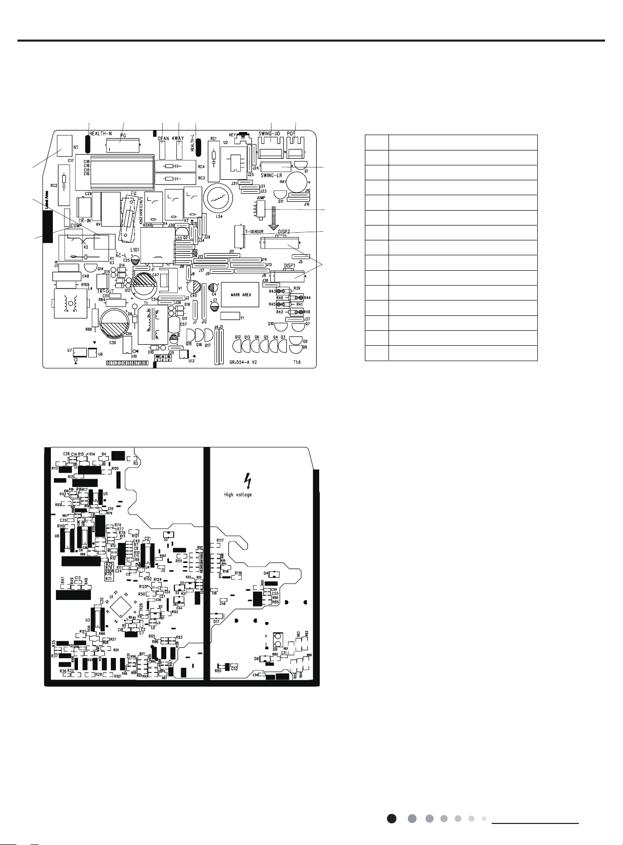
GWH12AFC-K3NNA1A/I 18/24K
● Top view
45 67 8910
3
2
1
11
12
13
14
Service Manual
No. Name
1 Compressor interface
2 Interface of power cord live wire
3 Interface of power cord neutral wire
4 Interface of cold plasma neutral wire
5 PG motor interface
6 Outdoor fan interface
7 4-way valve interface
8 Interface of cold plasma live wire
9 Up&down swing interface
10 PG motor feedback interface
11 Left&right swing interface
12 Jumper cap
13 Temperature sensor interface
14 Display board interface
● Bottom view
24
Technical Information

Service Manual
Buttons on Remote Controller
,the colour
which the model doesnt have, if pressthe corresponding button on the remote controller that the unit will keep
the original running status.
● When power is connected(stand by condition), you can operate the air conditioner through the remote controller
● Under on status, pressing the button on the remote controller, the signal icon " " on the display of rem
blink once and the air conditioner will give out a “de” sound, which means the signal has been sent to the ai
● Under off status, set temperature and clock icon will be displayed on the display of remote controller (If time
light functions are set, the corresponding icons will be displayed on the display of remote controller at the
status, the display will show the corresponding set function icons.
6. Function and Control
6.1 Remote Controller Introduction
1
3
6
8
10
11
12
1
On/Off button
Mode button
2
3
Fan button
▲
▲/ button
4
5
Swing button
6
Sleep button
2
7
Temp button
4
8
Turbo button
5
9
7
I Feel button
10
Timer button
9
11
X-Fan button
12
Light button
Temp. display type
:Indoor ambient temp.
Up & down swing
Send signal
Child lock
health function
ventilation operation
8 heating function
°C
Set temperature
Light function
I feel function
Set time
TIMER ON /TIMER OFF
Sleep mode
X-fan mode
Set fan speed
Operation mode
Auto mode
Cool mode
Dry mode
Fan mode
Heat mode
NOTICE:
:Set temp.
:Outdoor ambient temp.
Turbo mode
“ ” This is a general remote controller. Some models have this function while some
do not. Please refer to the actual models.
Note:
● This is a general use remote controller, it could be used for the air conditionerswith multifunction; For some function,
● After putting through the power, the air conditioner will give out a sound.Operation indicator " " is ON (red indicator
Technical Information
is different for different). After that, you can operate the air conditioner by using remote controller.
.
ote controller will
r conditioner.
r on, timer off and
same time); Under on
25
Service Manual
A
"
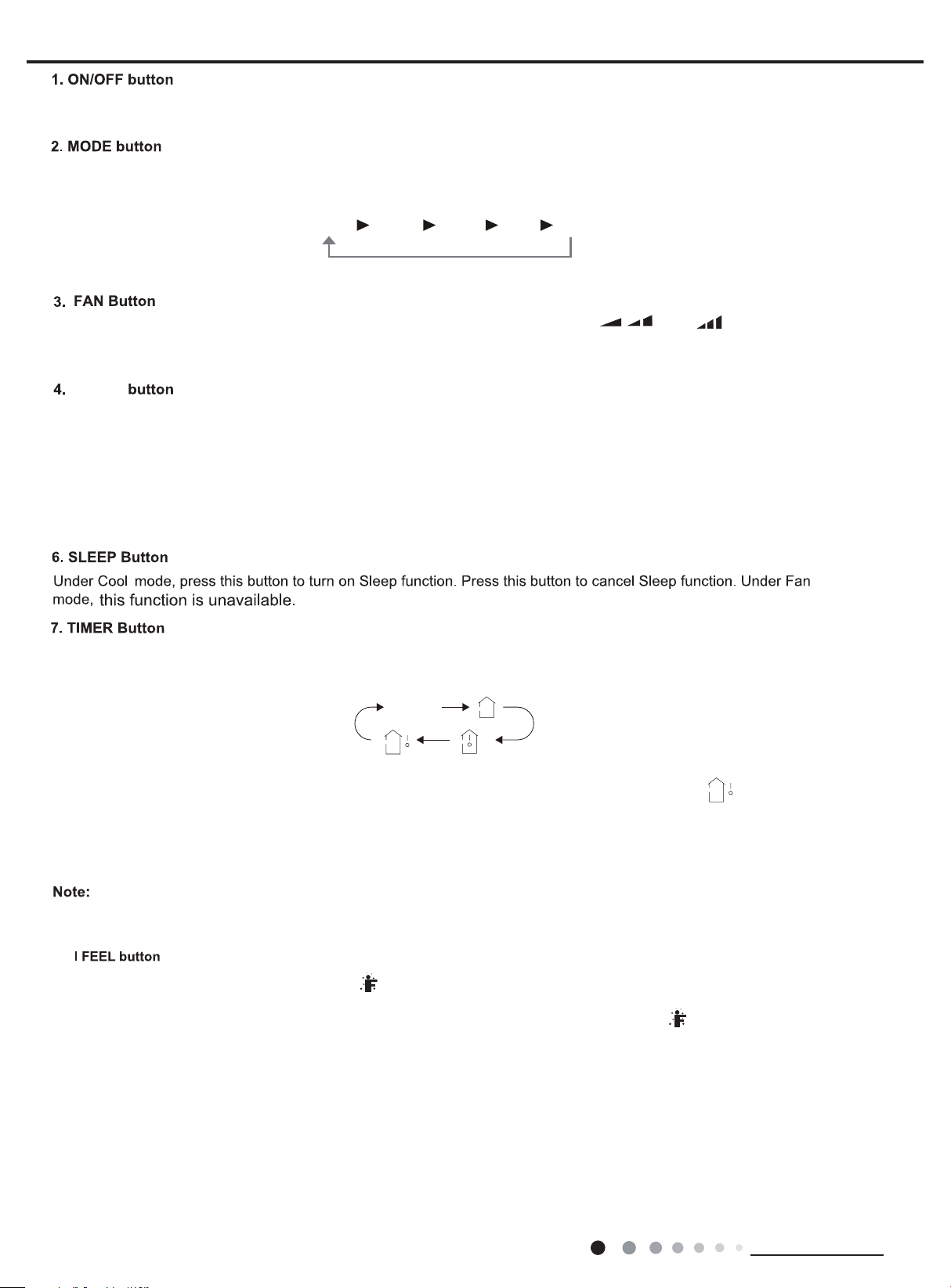
press this button again to cancel timer.
Press this button to turn on the unit. Press this button again to turn off the unit.
Each time you press this button,a mode is selected in a sequence that goes from AUTO, COOL, DRY, FAN, and HEAT *,
as the following:
UTO COOLDRY FANHEAT(Only for models with heating function.)
This button is used for setting Fan Speed in the sequence that goes from AUTO, , to , then back to Auto.
* Note:Fan speed under dry mode is low speed.
▲
▲ /
Press button to increase/decreaseset temperature. In AUTO mode,set temperature is not adjustable.
When setting Timer On or Timer Off, press "▲" or " " button to adjust the time.
5.SWING button
Press this button to set up & down swing angle.
Press this button, you can see indoor set temperature, indoor ambient temperature on indoor unit’s display. The setting on remote
controller is selected circularly as below:
▲ /
▲
▲
and Dry
no display
Note:
Outdoor temperature display is not available for some models. At that time, indoor unit receives " " signal, while it displays
indoor set temperature.
8.Turbo button
Under COOL or HEAT mode, press this button to activate / deactivate the Turbo function.
Not applicable for this unit.
9.
Press this button to start I FEEL function and " " will be displayed on the remote controller. After this function is set, the remote
controller will send the detected ambient temperature to the controller and the unit will automatically adjust the indoor temperature
according to the detected temperature. Press this button again to close I FEEL function and " " will disappear. When I FEEL
function is turned on, the remote controller should be put within the area where indoor unit can receive the signal sent by the
remote controller.
10.Timer button
● Under ON status, press this button to set timer OFF; Under OFF status, press this button to set timer ON.
● Press this button once and the characters of HOUR ON (OFF) will flash to be displayed. Meanwhile, press " " button or "
button to adjust timer setting (time will change quickly if holding " " or " " button). Time setting range is 0.5~24hours.
Press this button again to confirm timer setting and the characters of HOUR ON (OFF)will stop flashing.
If the characters are flashing but you haven’t press timer button,timer setting status will be quit after 5s.If timer is confirmer,
▲
▲
▲
▲
26
Technical Information
Service Manual
11.X-Fan button
12.Light button
Combination of " " and " " buttons: About lock
● Press this button in COOL or DRY mode to turn on X-fan function.
When this function is started up, indoor fan will still operate at low fan speed for a while after turning off the unit by remo
Press this button to turn on the display's light and press this button again to turn off the display's light.
te controller.
▲
Press " " and " " buttons simultaneously 3s to lock or unlock the keypad. If the remote controller is locked, is displayed.
In this case, pressing any button, blinks three times.
Combination of "MODE" and " " buttons:
About switch between Fahrenheit and centigrade
At unit OFF, press " MODE " and " " buttons simultaneously to switch between ℃ and ℉.
▲
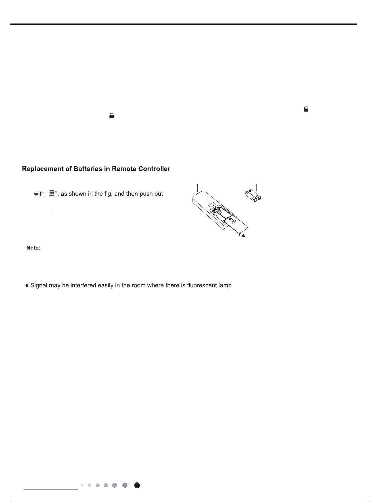
1. Press the back side of remote controller marked
the cover of battery box along the arrow direction.
▲
▲
▲
▲
signal sender battery
reinstall
2. Replace two 7# (AAA 1.5V) dry batteries, and
make sure the position of "+" polar and "-" polar
remove
are correct.
3. Reinstall the cover of battery box.
Cover of battery box
● During operation, point the remote control signal sender at the receiving
window on indoor unit.
●
The distance between signal sender and receiving window should be no more
than 6m, and there should be no obstacles between them.
or wireless telephone; remote controller should be close to indoor unit during
operation.
● Replace new batteries of the same model when replacement is required.
● When you don’t use remote controller for a long time, please take out the
batteries.
● If the display on remote controller is fuzzy or there’s no display, please
replace batteries.
Technical Information
27
 Loading...