

Gree GWH09AB-A3DNA1B/O, GWH12AB-A3DNA1B, GWH12AB-A3DNA1B/I, GWH12AB-D3DNA1B/I, GWH12AB-A3DNA1B/O Service Manual
...
GREE ELECTRIC APPLIANCES,INC.OF ZHUHAI
Service Manual
MODEL:GWH09AB-A3DNA1B
GWH12AB-A3DNA1B
GWH12AB-D3DNA1B
(Refrigerant R410A)

Table of Contents
Summary and features
..................................................................................1
Part 1 Safety Precautions
..........................................................................................2
Part 2 Specifications
.....................................................................................................3
Part 3 Construction Views
........................................................................................7
3.1 Indoor Unit ........................................................................................................
.....7
3.2 Outdoor Unit ..........................................................................................................7
Part 4 Refrigerant System Diagram
.....................................................................8
5.1 Electrical Data........................................................................................................9
5.2 Electrical Wiring......................................................................................................9
Part 5 Schematic Diagram
........................................................................................9
6.1 Remote Control Operations..................................................................................15
6.2 Changing Batteries and Notices ..........................................................................17
6.3 Description of Each Control Operation.................................................................18
Part 6 Function and Control
...................................................................................15
Part 7 Installation Manual
........................................................................................23
7.2 Installation Drawing..............................................................................................25
7.3 Install Indoor Unit.................................................................................................26
7.4 Install Outdoor Unit ..............................................................................................28
7.5 Check After Installation and Operation Test.........................................................29
5.3 Printed Circuit Board...........................................................................................
..12
7.1 Notices for Installation...........................................................................................23
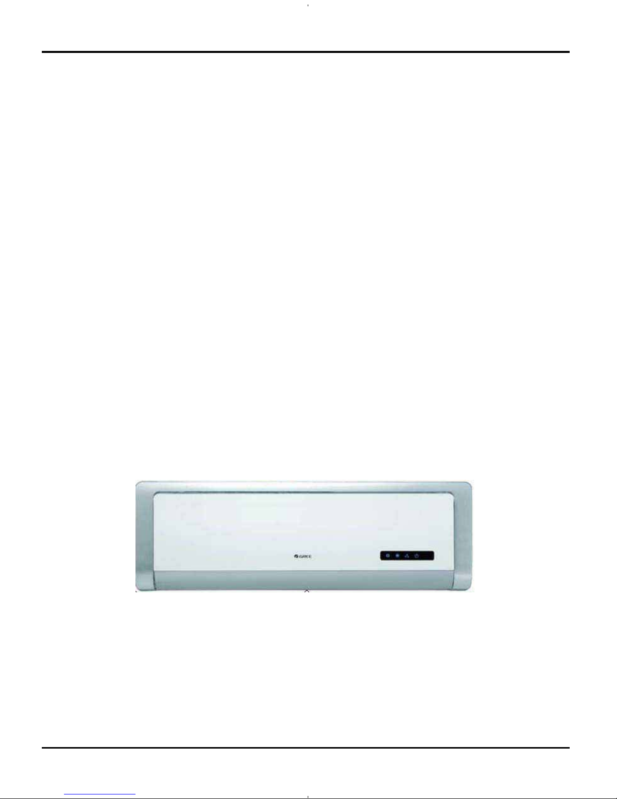
Table of Contents
Part 8 Exploded Views and Parts List
..............................................................30
Part 9 Troubleshooting
...............................................................................................40
9.1
Malfunction Analysis
.............................................................................................40
9.2
Flashing LED of Indoor/Outdoor Unit and Primary Judgement
............................44
9.3
How to Check Simply the Main Part
.....................................................................47
8.1 Indoor unit.............................................................................................................30
8.2 Outdoor unit..........................................................................................................34
Part10 Removal Procedure
.......................................................................................56
10.1
Removal Procedure of Indoor Unit
.....................................................................56
10.2
Removal Procedure of Outdoo
The pic. below is the actual panel and the vectorgraph in the manual is for reference only
.
r Unit
...................................................................59
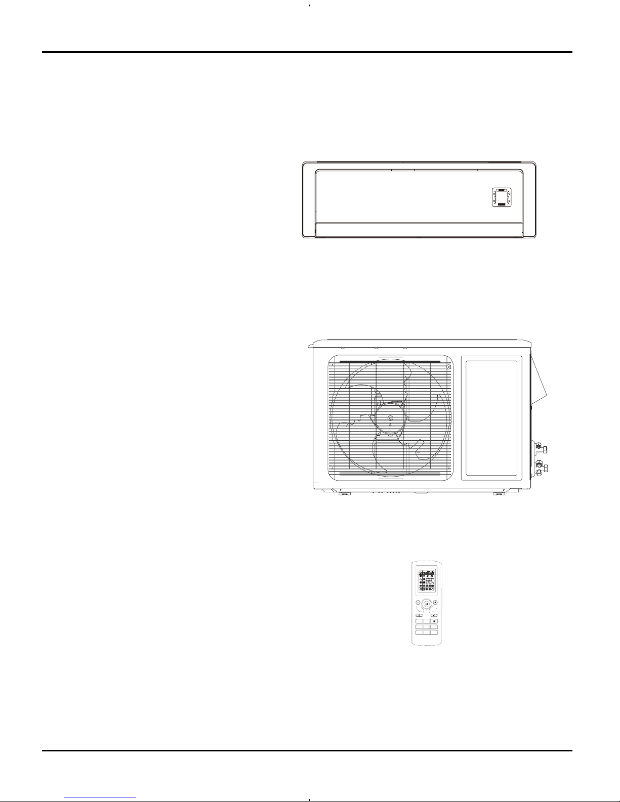
Summary and features
Indoor Unit
GWH09AB-A3DNA1B/I
GWH12AB-A3DNA1B/I
GWH12AB-D3DNA1B/I
Outdoor Unit
GWH09AB-A3DNA1B/O
GWH12AB-A3DNA1B/O
GWH12AB-D3DNA1B/O
Remote control window
YT1FF
Summary and features
FAN
MODE
IFEEL
CLOCK
TIMER
ON
X-FAN TEMP
TIMER
OFF
TURBO SLEEP LIGHT
1
1.Safety Precautions
Safety Precautions
Highly dangerous electrical voltages are used in this
system. Carefully refer to the wiring diagram and these
instructions when wiring. Improper connections inad-
equate grounding can cause accidental injury or death.
Ground the unit local electrical codes.
Connect all wiring tightly. Loose wiring may cause over-
heating at connection points and a possible fire hazard.
Make sure the ceiling/wall is strong enough to hold the
unit’s weight. The outdoor unit be installed in a
location where air and noise emitted by the unit will not
inside a room to prevent
"sweating" that can cause dripping
and
water
damage to
walls and floors.
The outdoor unit must be installed on stable, level surface,
where there is no accumulation of snow, leaves
or rubbish.
The unit should be installed according to the instructions
in order to minimize the risk of damage from earthquakes,
Keep your fingers and clothing away from any moving parts.
Caution
Never on the place where a combustible gas might
leak
When the unit is installed at telecommunication centers or
hospitals, take a proper provision against noise.
When installing at a watery place, provide an electric leak
Do not wash the unit with water.
Be very careful about unit transportation.The unit not
Do not touch the heat exchanger fins w th
Do not touch the compressor or refrigerant piping whithout
wearing glove
.
Do not operate the air conditioner without
air filter
.
i
Installing, starting up, and servicing air--conditioning equipment
can be hazardous due to system pressures, electrical components,
and equipment location (roofs, elevated structures, etc.).
Only trained, qualified installers and service mechanics should
install, start--up, and service this equipment.
Untrained personnel can perform basic maintenance functions such
as cleaning coils. All other operations should be performed by
trained service personnel.
When working on the equipment, observe precautions in the
literature and on tags, stickers, and labels attached to the
equipment.
Follow all safety codes. Wear safety glasses and work gloves. Keep
quenching cloth and fire extinguisher nearby when brazing. Use
care in handling, rigging, and setting bulky equipment.
Read these instructions thoroughly and follow all warnings or
cautions included in literature and attached to the unit. Consult
local building codes and current editions of the National Electrical
Code ( NEC ).
Recognize safety information. This is the safety--alert symbol
!
!
.
When you see this symbol on the unit and in instructions or
manuals, be alert to the potential for personal injury.Understand
these signal words: DANGER, WARNING, and CAUTION.
These words are used with the safety--alert symbol. DANGER
identifies the most serious hazards which will result in severe
personal injury or death. WARNING signifies hazards which
could result in personal injury or death. CAUTION is used to
identify unsafe practices which may result in minor personal injury
or product and property damage. NOTE is used to highlight
suggestions which will result in enhanced installation, reliability, or
operation.
or
according to
!
WARNING
ELECTRICAL SHOCK HAZARD
Failure to follow this warning could result in personal injury
or death.
Before installing, modifying, or servicing system, main
electrical disconnect switch must be in the OFF position.
There may be more than 1 disconnect switch. Lock out and
tag switch with a suitable warning label.
should
refrigerant or condensate line
running
Contact of refrigerant and fire generates poisonous gas.
Use specified refrigerant only.
UNIT DAMAGE HAZARD
Failure to follow this caution may result in equipment
damage or improper operation.
Never use the system compressor as a vacuum pump.
CAUTION
!
Refrigerant and indoor coil should be evacuated using the
recommended deep vacuum method of 500 microns. The alternate
triple evacuation method may be used if the procedure outlined
below is followed. Always break a vacuum with dry nitrogen.
Clear the site after installation. Make sure no foreign objects
are left in the unit.
Always ensure effective grounding for the unit.
install
, or it may lead to fire or explosion.
should
Should any emergency occur, stop the unit and disconnect the
power immediately.
hurricanes or strong winds.
lines
ground fault breaker
.
be carried by only one person if it is more than 45lb
.
bare hands.
disturb the neighbors
.
Properly insulate any
2
2.Specifications
Specifications
Unit
GWH09AB-A3DNA1B GWH12AB-A3DNA1B
CB11500550 CB11500570
Rated Voltage V
115 115
Rated Frequency Hz 60 60
Phases 1 1
Outdoor Outdoor
Btu/h 9000(400011950) 12000(450013000)
Btu/h 9500(341212500) 11700(320014000)
W630(1661180) 960(1601180)
W 680(2001230) 1140(4001250)
A 8.5 14.5
W 1100 1300
A10 12
CFM
300
300
gal./hr
0.32
0.37
BTU/W 14.3 12.5
W/W 4.04 3.34
W/W 23 2 2
W/W 9.8 8.9
sq.ft.
129-194 172-258
Model of indoor unit GWH09AB-A3DNA1B/I GWH12AB-A3DNA1B/I
Fan Type Cross-flow Cross-flow
Diameter Length(DXL) inch ĭ(3-3/8)X(26-3/10) ĭ(3-3/8)X(26-3/10)
Fan Motor Cooling Speed (SH/H/M/L/SL) r/min 1400/1150/1050/900/- 1500/1150/1050/900/-
Fan Motor Heating Speed (SH/H/M/L/SL) r/min 1450/1250/1150/1050/400 1450/1250/1150/1050/400
Output of Fan Motor W 10 10
Fan Motor RLA A / /
Fan Motor Capacitor ȝF/ /
Input of Heater W / /
Evaporator Form Aluminum Fin-copper Tube Aluminum Fin-copper Tube
Pipe Diameter inch
ĭ11/40
ĭ11/40
Row-fin Gap inch 2-1/17 2-1/17
Coil Length (LXDXW) inch
(25-7/8)X1X(11-2/9) (25-7/8)X1X(11-2/9)
Swing Motor Model MP28VB MP28VB
Output of Swing Motor W 2 2
Fus e A 3.15 3.15
Sound Pressure Level (SH/H/M/L/SL) dB (A) 42/38/30/28/- 42/38/30/28/-
Sound Power Level (SH/H/M/L/SL) dB (A) 52/48/40/38/- 52/48/40/38/-
Dimension (WXHXD) inch
34.3X11.1X7
34.3X11.1X7
Dimension of Carton Box (W/H/D) inch 36.8X14.7X10.2
36.8X14.7X10.2
Dimension of Package (W/H/D) inch
36.8X14.7X10.2 36.8
X14.7X10.2
Net Weight
lb.
26 26
Gross Weight lb. 33
33
ValueParam eter
Model
Product Code
Power
Supply
Power Supply Mode
l
Cooling Capacity (MinMax)
Heating Capacity (MinMax)
Cooling Power Input (MinMa x)
Heating Power Input (MinMa x)
Cooling Power Current
Heating Power Current
Rated Input
Rated Current
Air F l ow Volu me
Moisture Removal
Application Area
Indoor
Unit
EER
COP
SEER
HSPF
3
A 8 13
The above data is subject to change without notice. Please refer to the nameplate of the unit.
Specifications
Model of Outdoor Unit GWH09AB-A3DNA1B/O GWH12AB-A3DNA1B/O
Compressor Manufacturer/Trademark
CHINA
RESOURCES(SHENYANG)
SANYO COMPRESSOR CO.
LTD ./S ANYO
CHINA
RESOURCES(SHENYANG)
SANYO COMPRESSOR CO.
LTD ./S ANYO
Compressor Model C-6RZ110H1A C-6RZ110H1A
Compressor Oil FV50S FV50S
Compressor Type Rotary Rotary
L.R.A. A 33.00 33
Compressor RLA A 4.59 4.59
Compressor Power Input W 800 800
Overload Protector Int11l-3979 Int11l-3979
Throttling Method Electron expansion valve Electron expansion valve
Operation temp ºF 61
86 61
86
Ambient temp (cooling) ºF
41
115 41115
Ambient temp (heating) ºF
586
5
86
Condenser Form Aluminum Fin-copper Tube Aluminum Fin-copper Tube
Pipe Diameter inch ĭ3/8 ĭ3/8
Rows-fin Gap inch
2-1/18
2-1/18
Coil Length (LXDXW) inch (29-2/5)X(1-3/4)X20
(29-2/5)X(1-3/4)X
20
Fan Motor Speed rpm 830 830
Output of Fan Motor W 30 30
Fan Motor RLA A / /
Fan Motor Capacitor ȝF/ /
Air Flow Volume of Outdoor Unit
CFM
1059 1177
Fan Type Axial-flow Axial-flow
Fan Diameter inch ĭ(15-3/4)
ĭ
(15-3/4)
Defrosting Method Automatic Defrosting Automatic Defrosting
Clim ate Type T1 T1
Is ol ati on I I
Mois ture Protection IP24 IP24
Permissible Excessive Operating
Pressure for the Discharge Side
MPa 3 .8 3 .8
Permissible Excessive Operating
Pressure for the Suction Side
MPa 1 .2 1 .2
Sound Pressure Level (H/M/L) dB (A) 52/-/- 55/-/-
Sound Power Level (H/M/L) dB (A) 62/-/- 65/-/-
Dimension (WXHXD) inch
33.3X21.3X12.6
33.3X23.2X12.6
Dimension of Carton Box (W/H/D) inch 34.5X22.8X14.2 34.5X24.8X14.2
Dimension of Package (W/H/D) inch
34.5X22.8X14.2 34.5X24.8X14.2
Net Weight lb. 88 90
Gross Weight lb.
96
99
Refrigerant R410A R410A
Refrigerant Charge
oz. 47.6
47.6
Precharge line length
ft.
16
16
Gas Additional Charge lb./ft. 0.14 0.14
Outer Diameter Liquid Pipe inch ĭ1/4
ĭ1/4
Outer Diameter Gas Pipe inch ĭ3/8
ĭ1/2
Max Distance Height ft. 33 33
Max Distance Length ft. 66
66
Outdoor
Unit
Connecti
on Pipe
4
Specifications
Unit Value
GWH12AB-D3DNA1B
CB11500380
Rated Voltage V
208/230
Rated Frequency Hz 60
Phas es 1
Outdoor
Btu/h 12000(450013000)
Btu/h 13000(320014000)
W960(1601180)
W 1140(4001250)
A5
A5.5
W 1200
A6
CFM
330
gal./hr. 0.37
BTU/W 12.5
W/W 3.34
W/W 22
W/W 10.5
sq.ft.
172-258
Model of indoor unit GWH12AB-D3DNA1B/I
Fan Type Cross-flow
Diameter Length(DXL) inch
ĭ(3-3/8)X(26-3/10)
Fan Motor Cooling Speed (SH/H/M/L/SL) r/min 1500/1150/1050/900/-
Fan Motor Heating Speed (SH/H/M/L/SL) r/min 1450/1250/1150/1050/400
Output of Fan Mo tor W 10
Fan Motor RLA A /
Fan Motor Capacitor ȝF/
Input of Heater W /
Evaporator Form Aluminum Fin-copper Tube
Pipe Diameter inch ĭ11/40
Row-fin Gap inch 2-1/17
Coil Length (LXDXW) inch (25-7/8)X1X(11-2/9)
Sw in g Moto r Model MP2 8VB
Output of Swi ng Motor W 2
Fus e A 3.15
Sound Pressure Level (SH/H/M/L/SL) dB (A) 47/38/30/28/-
Sound Power Level (SH/H/M/L/SL) dB (A) 57/48/40/38/-
Dimension (WXHXD) inch 34.3X11.1X7
Dimension of Carton Box (W/H/D) inch 36.8X14.7X10.2
Dimension of Package (W/H/D) inch 36.8X14.7X10.2
Net Weight lb. 26
Gross Weight lb. 33
Indoor
Unit
EER
COP
SEER
HSPF
Rated Current
Air F l ow Volum e
Moisture Removal
Application Area
Heating Power Input (Min
Ma x)
Cooling Power Current
Heating Power Current
Rated Input
Power Supply Mode
l
Cooling Capacity (MinMa x)
Heating Capacity (MinMa x)
Cooling Power Input (MinMa x)
Param eter
Model
Product Code
Power
Supply
5
Specifications
Model of Outdoor Unit GWH12AB-D3DNA1B/O
Compressor Manufacturer/Trademark
CHINA RESOURCES(SHENYANG) SANYO
COMPRESSOR CO. LTD./SANYO
Compressor Model C-6RZ110H1A
Compressor Oil FV50S
Compressor Type Rotary
L.R.A. A 33.00
Compressor RLA A 4.59
Compressor Power Input W 800
Overload Protector Int11l-3979
Throttling Method Electron expansion valve
Operation temp ºF 61
86
Ambient temp (cooling) ºF
41115
Ambient temp (heating) ºF
5
86
Condenser Form Aluminum Fin-copper Tube
Pipe Diameter inch ĭ3/8
Rows-fin Gap inch 2-1/18
Coil Length (LXDXW) inch (29-2/5)X(1-3/4)X22
Fan Motor Speed rpm 830
Output of Fan Motor W 30
Fan Motor RLA A /
Fan Motor Capacitor ȝF/
Air Flow Volume of Outdoor Unit
CFM 1177
Fan Type Axial-flow
Fan Diameter inch ĭ(15-3/4)
Defrosting Method Automatic Defrosting
Climate Type T1
Isolation I
Moisture Protection IP24
Permissible Excessive Operating Pressure for the
Discharge Side
PSI
551
Permissible Excessive Operating Pressure for the
Suction Side
PSI
174
Sound Pressure Level (H/M/L) dB (A) 55/-/-
Sound Power Level (H/M/L) dB (A) 65/-/-
Dimension (WXHXD) inch 33.3X23.2X12.6
Dimension of Carton Box (W/H/D) inch 34.5X24.8X14.2
Dimension of Package (W/H/D) inch 34.5X24.8X14.2
Net Weight lb. 90
Gross Weight lb. 99
Refrigerant R410A
Refrigerant Charge
oz. 45.8
Precharge line length
ft.
16
Gas Additional Charge lb./ft. 0.14
Outer Diameter Liquid Pipe inch ĭ1/4
Outer Diameter Gas Pipe inch ĭ1/2
Max Distance Height ft. 33
Max Distance Length
ft. 66
Outdoor
Unit
Connecti
on Pipe
The above data is subject to change without notice. Please refer to the nameplate of the unit.
6
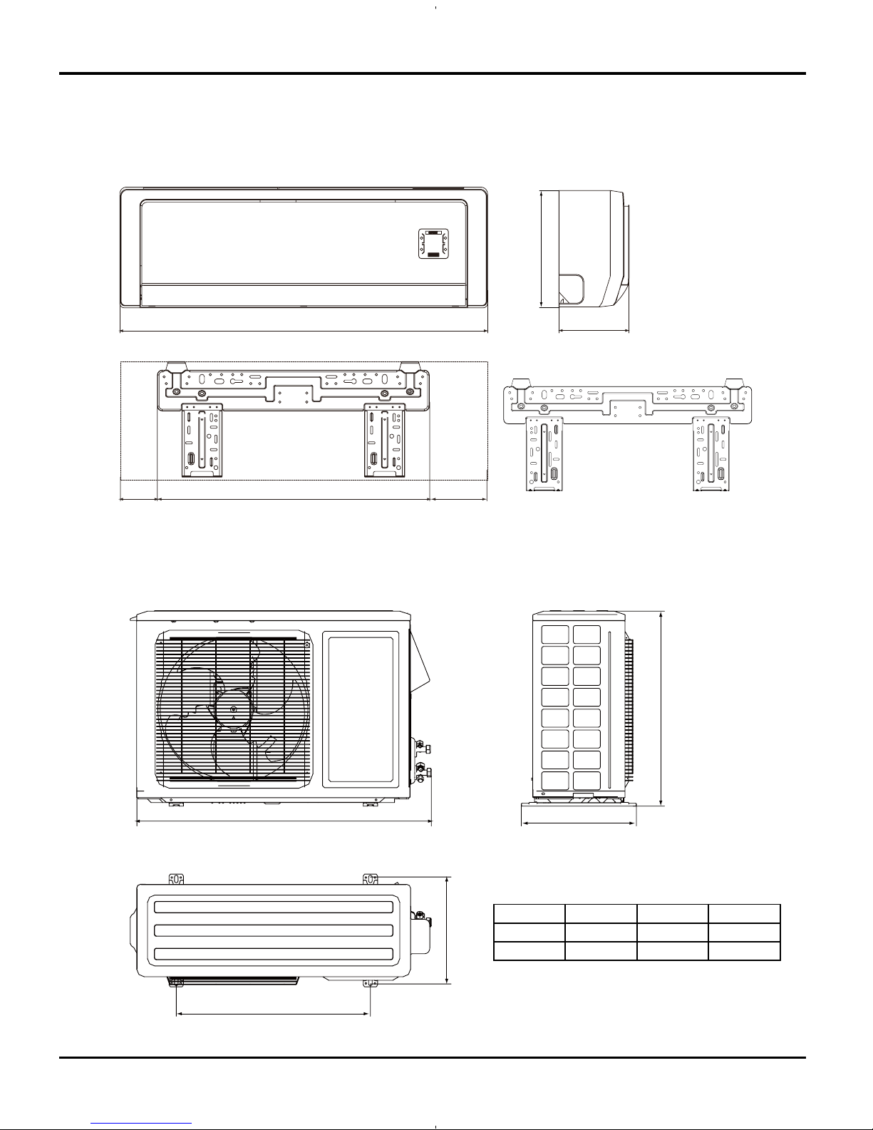
3. Construction Views
3.1 Indoor Unit (THE SAME DIMS FOR 9k12k)
Constrction views
Unit:inch
4
34-1/3
7
23-4/5
6-8/15
11-1/7
12K Unit:
3.2 Outdoor Unit
D
21-1/4
11-1/4
H
W
Model W H D
09K
33-3/8
21-1/4 12-3/5
12K 33-3/8 23-2/9 12-3/5
7
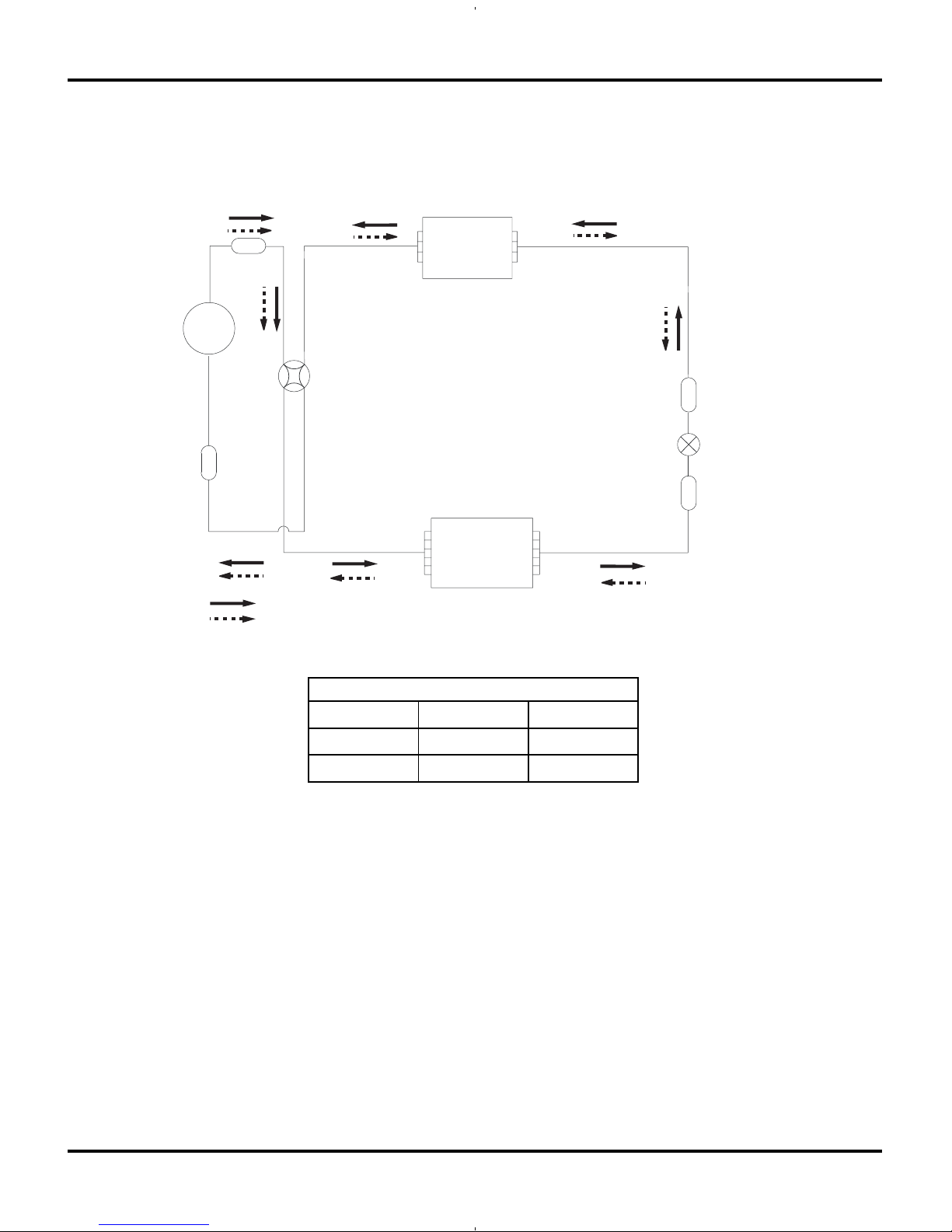
4. Refrigerant System Diagram
Refrigerant System Diagram
Strainer
Strainer
Muffler
4-Way valve
Expansion valve
Heat exchanger
( INDOOR )
Heat exchanger
( OUTDOOR )
rotalumucca-buS
rosserpmoC
Cooling
Heating
Refrigerant Pipe Diameter
Liquid Gas
09K
1/4ą 3/8ą
12K
1/4ą 1/2ą
8
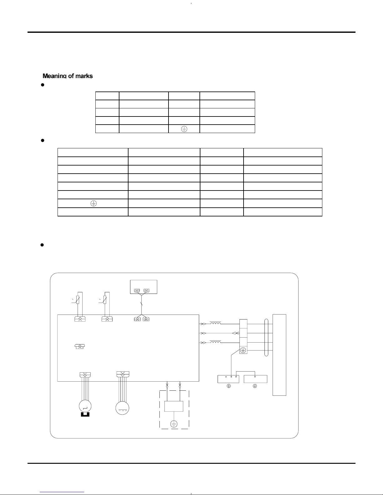
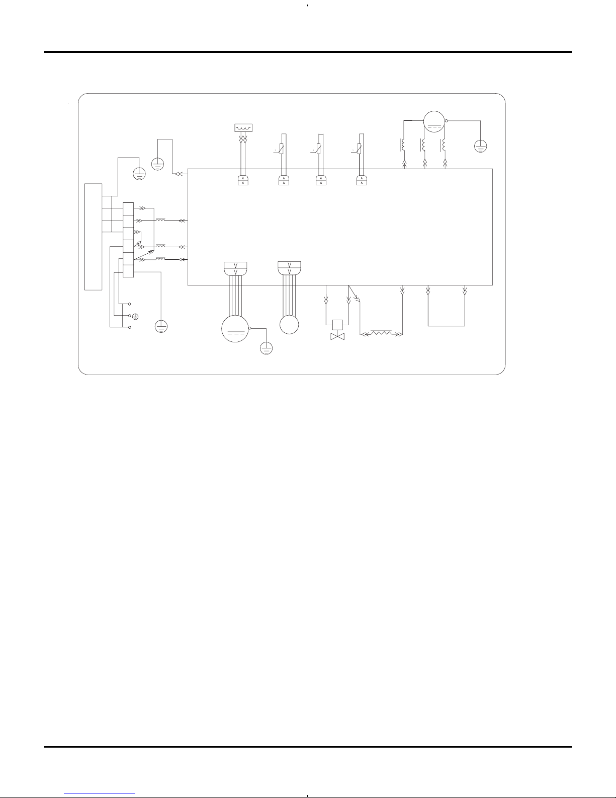
5. Schematic Diagram
5.1 Electrical Date
5.2 Electrical wiring
Outdoor Unit
Symbol Color s ymbol Symbol Color symbol
WH
WHITE
BN
BROWN
YE
YELL OW
BU
BLUE
RD
RED
BK
BLACK
YEGN
YELLOW GREEN Ground
Indoor Unit
Indoor Unit
Schematic Diagram
Symbol Parts name Symbol Color symbol
L1 L2
1OLQH)URQWOLQH
WH
WHITE
4YV
ZD\YDOY
YE
YELLOW
EKV
electric expansion valv
RD
RED
L reactor BN
SAT OVERLOAD BN BROWN
COMP
COMPRESSOR
BU
BLUE
Ground
BK
BLACK
YEGN
YELLOW GREEN
AP1 DISPLAY
EVAPORATOR
ELECTRIC BOX
W5
BK
N1
W2 YEGN
W1YEGN
COM-INNER
3
2
OUTDOOR UNIT
N(1)
AP2
L
W3
BN
W4
BU
XT1
G
HEALTH-LHEALTH-N
YEGN
BURD
GG
FAN MOTOR
STEP MOTOR
ROOM TUBE
DISP3 DISP4
00
TEM.SENSOR
TUBE
ROOM
TEM.SENSOR
RT1 RT2
JUMP
L1
L1
COOL PLASMA
GENERATOR
M
M
SWING-UD CN1
(1) Models GWH09AB-A3DNA1B/I ,GWH12AB-A3DNA1B/I
9
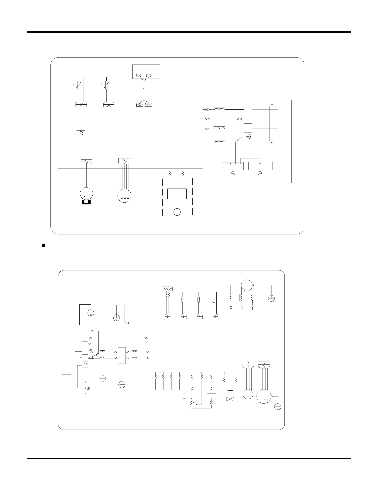
Outdoor Unit
Schematic Diagram
4YV
RT5
0
0
RT4
0
RT3
OUTROOM
EXHAUST
OUTTUBE
OFAN
E
OVERHEAT
R
E
C
S
U
V
W
CT1,2
AP1
W3YEGN
W10 RD
COMP
W8 YEGN
FAN MOTOR
W5 BU
W6 YE
W7 BK
AC-N1
AC-L1
4V
AC-N2
COMU
EKV
CN1
TEM.SENSOR
OUTROOM
EXHUAST
TEM.SENSOR
TEM.SENSOR
TUBE
W2 BU
W1 BN
W4 BK
G
G
I
N
D
O
O
R
U
N
I
T
W13 YEGN
POWER
N
L
L
N
N(1)
3
2
L2L2L2
L1
L1
G
G
G
W15 BU
W14 BN
W16 WH
W17 RD
G
L4
L4
W23 OGW20 BU
W22 WH
W21 BN
AC-L2 AC-L4AC-N5AC-N3 AC-N4 AC-L2AC-L3
W19 BU W24 RD
W18 YEGN
COMP
M
XT2
3
4
E
2
1
FILTER
C4
C3
2
1
2
1
(2) Model GWH12AB-D3DNA1B/I
AP1 DISPLAY
EVAPORATOR
ELECTRIC BOX
W5 BK
N1
W2 YEGN
W1 YEGN
COM-INNER
3
2
OUTDOOR UNIT
N(1)
AP2
L
W3 BN
W4 BU
XT1
G
HEALTH-L HEALTH-N
YEGN
BURD
GG
FAN MOTOR
STEP MOTOR
ROOM TUBE
DISP3 DISP4
00
TEM.SENSOR
TUBE
ROOM
TEM.SENSOR
RT1 RT2
JUMP
E
W6 YEGN
L1
L1
L1
COOL PLASMA
GENERATOR
M
M
SWING-UD CN1
(1) Models GWH09AB-A3DNA1B/O,GWH12AB-A3DNA1B/O
10
These circuit diagrams are subject to change without notice, please refer to the one supplied with the unit.
4YV
RT5
0
0
RT4
0
RT3
OUTROOM
EXHAUST
OUTTUBE
OFAN
E
OVERHEAT
R
E
C
S
U
V
W
CT1,2
AP1
W3 YEGN
W10 RD
COMP
W8 YEGN
FAN MOTOR
W5 BU
W6 YE
W7 BK
N1
AC-L1
4V
AC-L2
AC-L3
N2 N3
L
COMU
W 9 BU
W11 OG
W12 WH
EKV
CN1
TEM.SENSOR
OUTROOM
EXHUAST
TEM.SENSOR
TEM.SENSOR
TUBE
W2 BU
W1 BN
W4 BK
G
G
I
N
D
O
O
R
U
N
I
T
W
13 YEGN
POWER
L1
L
N
N(1)
3
2
L2L2L2
L1
L1
G
G
G
W15 BU
W14 BN
L1
L2
G
COMP
M
XT2
Schematic Diagram
(2) Models GWH09AB-A3DNA1B/O,GWH12AB-A3DNA1B/O
11
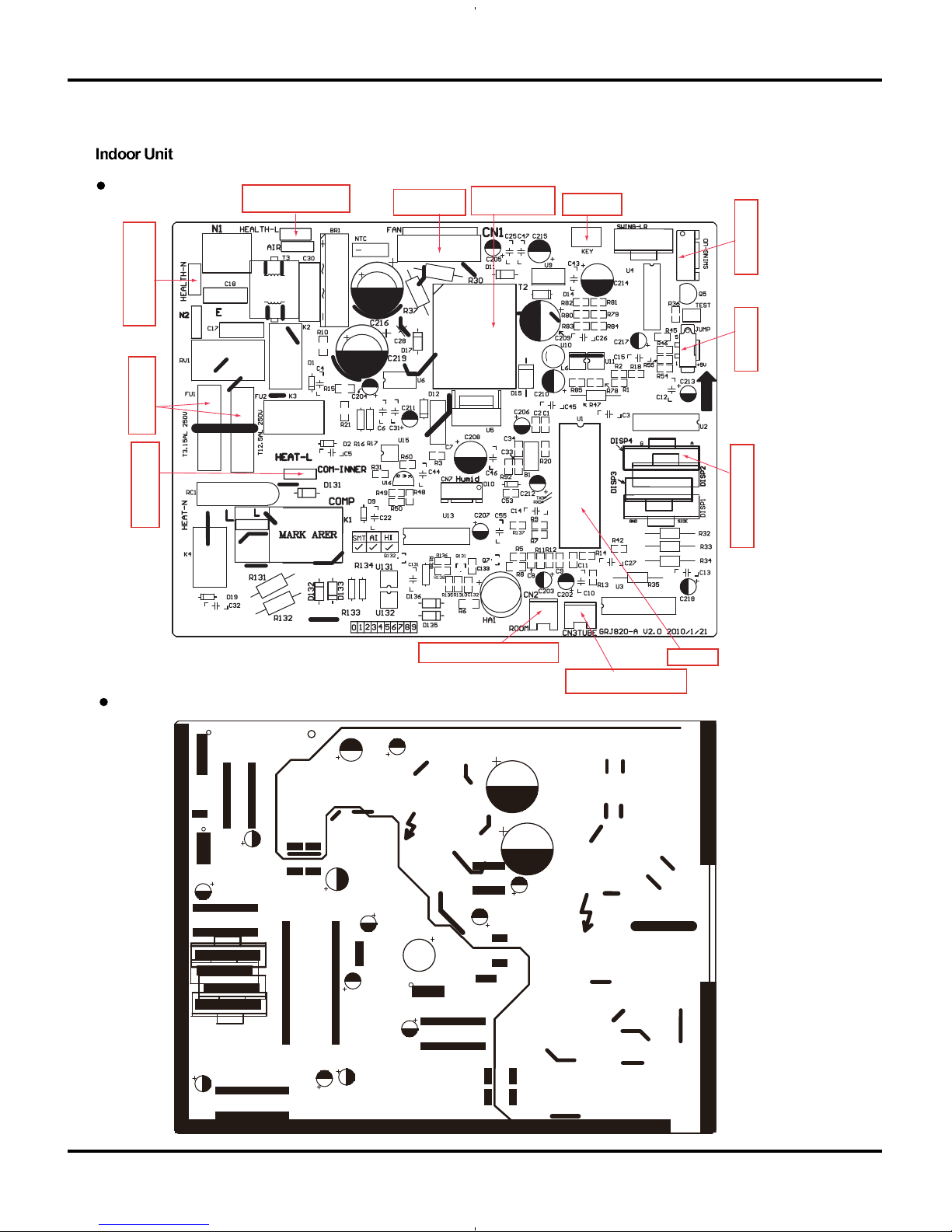
Interface for live wire
of healt h function
Interface of
indoor fan
Tra ns for mer wi th
high freq uency
Auto button
Vertical swing
Jumper cap
Interface for display
Main chip
Indoor pipe temp sensor
Indoor tambien temp sensor
Interface for
communication
Protective tube
Interface for null wire
of health function
5.3 Printed Circuit Board
TOP VIEW
BOTTOM VIEW
Schematic Diagram
12
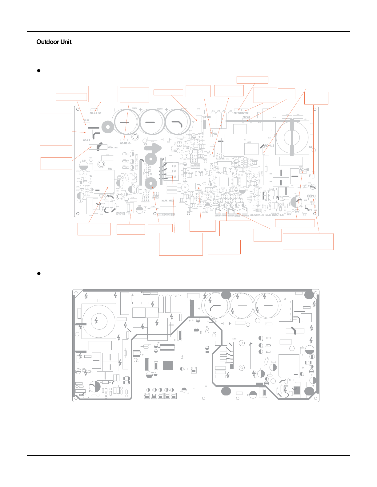
TOP VIEW
BOTTOM VIEW
(1) Models GWH09AB-A3DNA1B/O , GWH12AB-A3DNA1B/O
Schematic Diagram
Jumper null wire
Positive pole
of big capacitor
(brown wire)
Terminal for fan
Terminal for
4-way valve
Jumper null wire
Terminal for
null wire of
4-way valve
Jumper
live wire
Terminal for
live wire
Terminal for
ground wire
Terminal for communication
wire connecting to black
communication wire of IDU.
Terminal for null wire
Outdoor pipe
temp sensor
Outdoor ambient
temp se nsor
Compressor
discha rge temp
sensor
Overload
temp s ensor
Three-phase terminal
of compressor
Phase U-blue wire
Phase Y-yellow wire
Phase W-red wire
IPM module
Voltage
regulator 7805
Tra ns for mer with
high freq uency
Protective tube
for switch power
Jumper live wire,
joint terminal for
positive pole and
negative pole of
two capacitors(
orange wire)
Negative pole
of big capacitor
(blue wire)
electronic
expansion valve
13
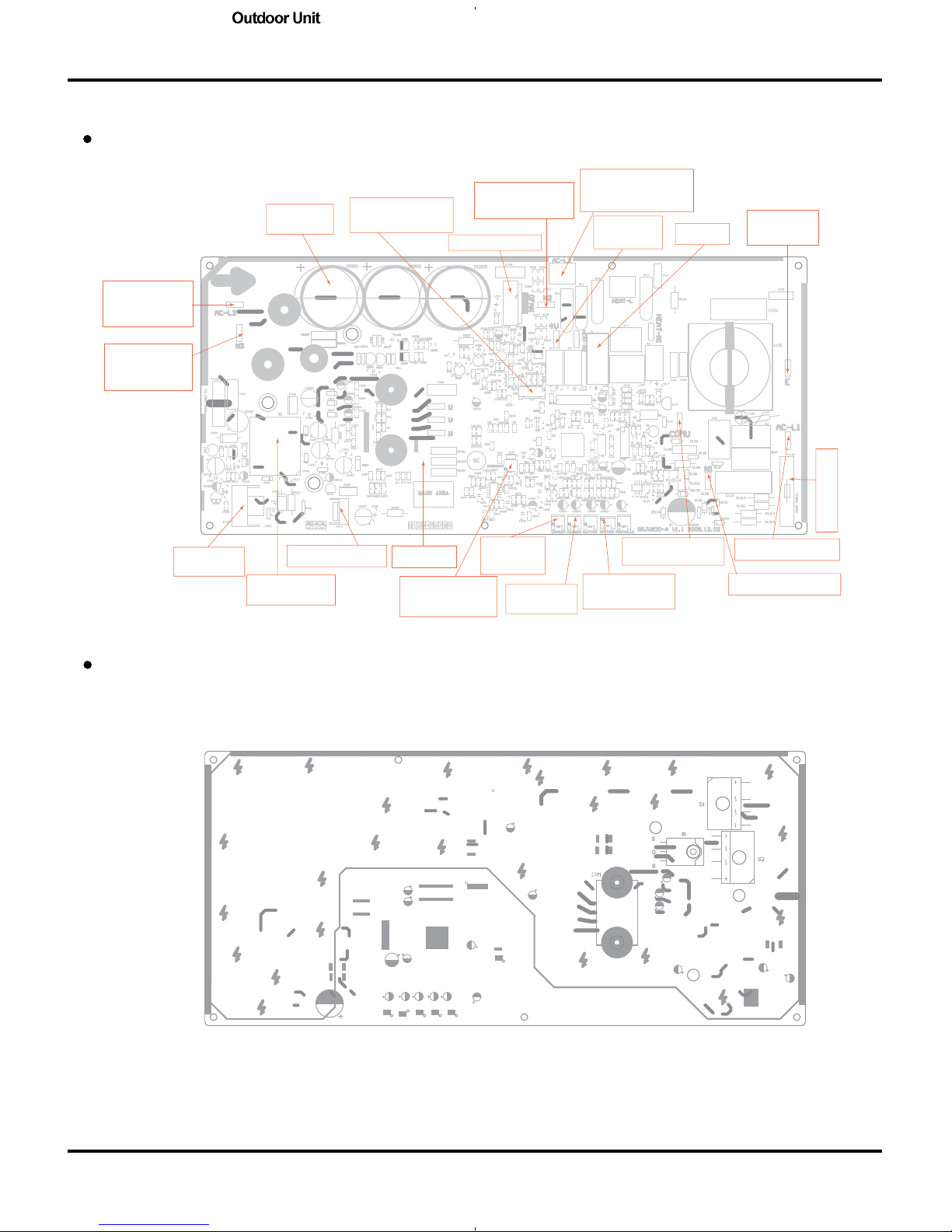
TOP VIEW
BOTTOM VIEW
Schematic Diagram
(2) Model GWH12AB-D3DNA1B/O
Electrolysis
condenser
electronic
expansion valve
Terminal for DC fan
Jumper terminal
for null wire,
connecting to N3
Terminal for live wire
connecting to reactor
and 4-way valve
Main relay
Terminal for
ground wire
Protective tube
Terminal for live wire
Terminal for null wire
Terminal for
communication wire
Outdoor pipe
temp sensor
Outdoor ambient
temp sensor
Compressor
discha rge
temp se nsor
Terminal for
overload protector
of compressor
IPM module
Voltage regulator7805
Transformer with
high freq uency
Chip for
switch power
Jumper terminal
for null wire,
connecting to N2
Terminal for live
wire, connecting
to reactor
Terminal for
4-way valve
14
6. Function and Control
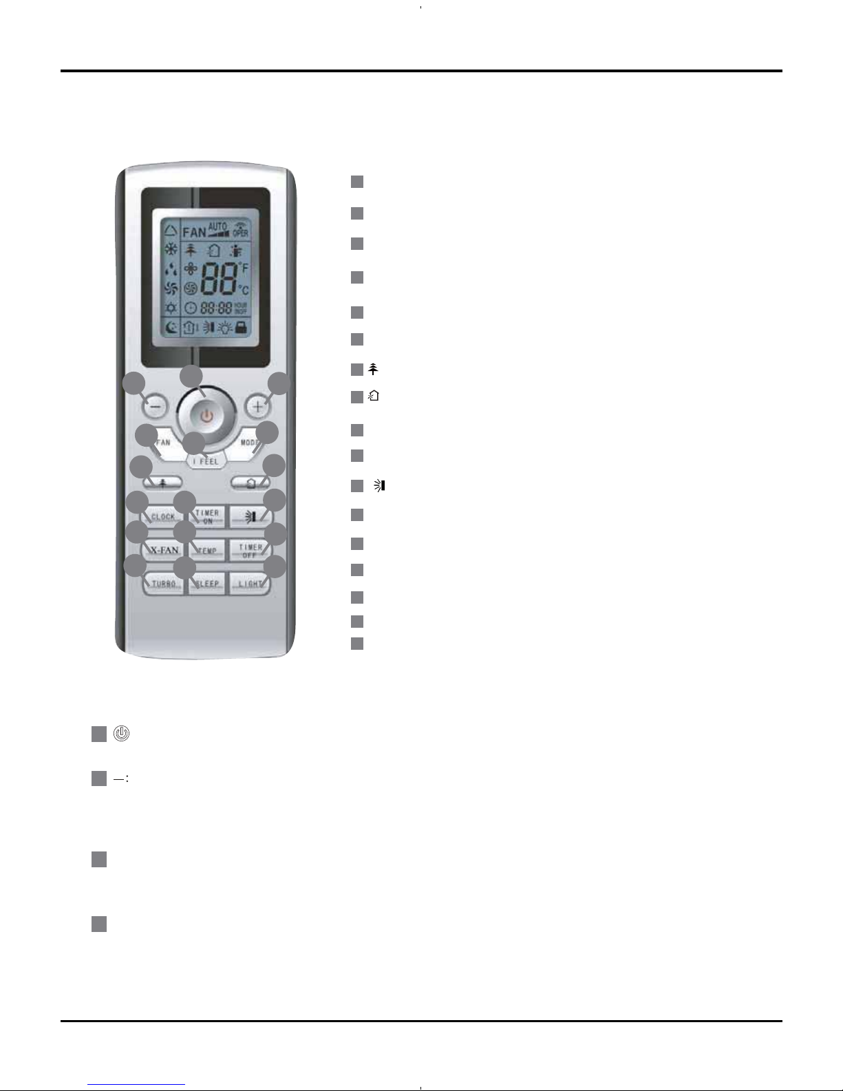
6.1 Remote Control Operations
Function and Control
Timer ON Button
TIMER OFF Button
Clock Button
X-FAN Button
Temperature Displaye Button
TURBO Button
Sleep Mode Button
Light Mode Button
ON/OFF Button
1
7
6
I FEEL Button
MODE Button
5
3
Setpoint Temperature DOWN Button
2
FAN Speed Button
4
11
10
14
9
12
13
15
16
17
8
3
14
9
10
13
16
12
5
4
15
11
8
17
7
2
1
6
+
:
FAN :
1
3
2
4
Press this button, the unit will be turned on, press it once more, the unit will be turned off.
To lower temperature set point. Press this button, sets temperature,when unit is on . Continuously press and hold this
button for more than 2 seconds,the corresponding contents will be changed rapidly,but in AUTO mode, set tempera-
ture is not adjustable.
.
To increase temperature set point. Press this button, the temperature can be set up, continuously press this button and
hold for two seconds, the relative contents can quickly change, but in AUTO mode, set temperature is not adjustable.
Setpoint Temperature UP Button
HEALTH function Button
AIR function Button
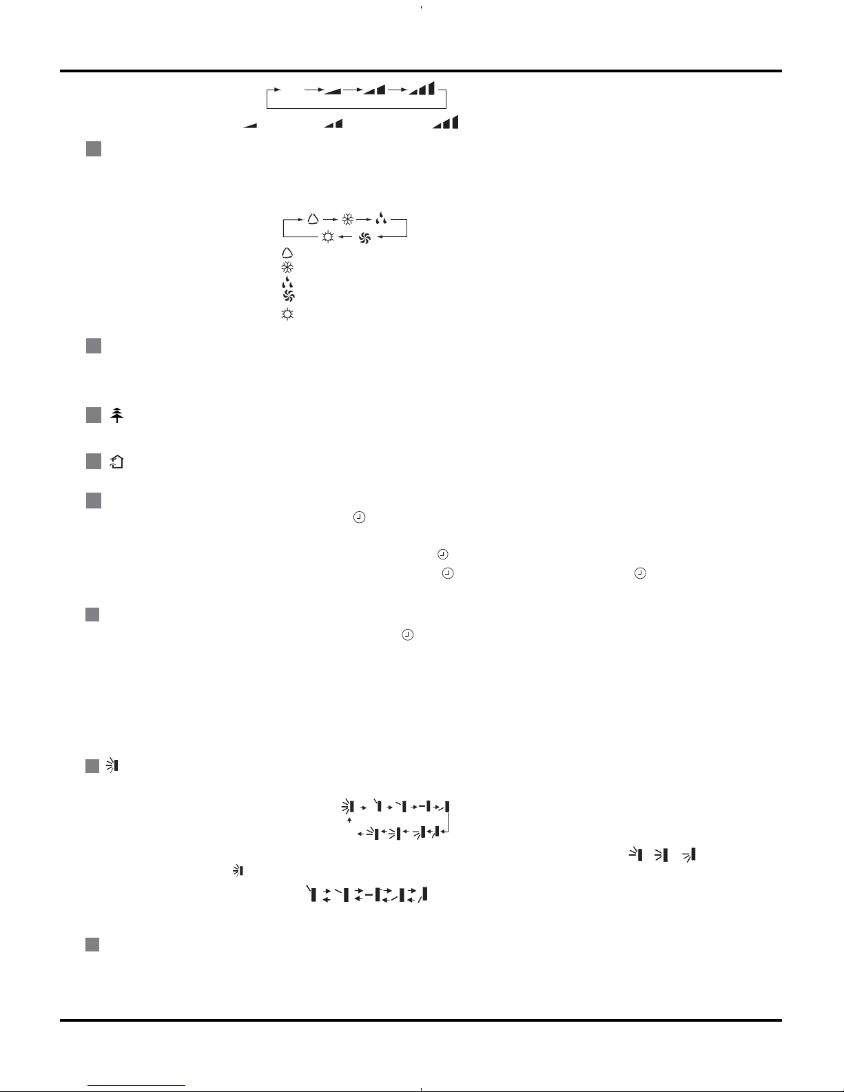
Press this button, Auto, Low, Middle, High speed can be circularly selected. After powered on, Auto fan speed is default.
Under Dehumidify mode, Low fan speed only can be set up.
(
X-FAN is the alternative expression of
BLOW for the purpose of understanding.)
15
Function and Control
CLOCK
:
9
8
7
I FEEL :
5
MODE
:
6
Press this button, I FEEL On and I FEEL Off can be selected.In the I FEEL function.
The unit will adjust temperature automatically according to the sensed temperature.
TIMER ON
:
11
10
X-FAN :
12
OFF
This is an universal use remote controller. If remote controller sends the following three kinds of status , or , the swing
status of main unit will be which indicates the guide louver swings up and down between that all five positions:
:
Press this button, Auto, Cool,Dry, Fan, Heat mode can be selected circularly. Auto mode is default while power on. Under Auto
mode, the temperature will not be displayed; In this mode, the unit will automatically select the suitable operation mode in accordance with the room temperature to make the room more comfortable for you.
AUTO
COOL
DRY
FAN
Note:Only for models with heating function.
HEAT
Press this button to set HEALTH function ON or OFF. After the unit is turned on, it defaults to HEALTH function ON.
Press this button to select AIR function ON or OFF.
Press this button, the clock can be set up,signal blink and display.Within 5 seconds, the value can be adjusted by pressing
+ or - button, if continuously press this button for 2 seconds above,in every 0.5 seconds, the value on ten place of Minute will
be increased 1. During blinking, repress the Clock button, signal will be constantly displayed and it denotes the setting succ-
eeded. After powered on, 12:00 is defaulted to display and signal will be displayed. If there is signal be displayed that
denotes the current time value is Clock value, otherwise is Timer value.
Timer On setting: Signal “ON” will blink and display, signal will conceal, the numerical section will become the timer on setting
status. During 5 seconds blink,by pressing + or - button to adjust the time value of numerical section, every press of that button, the value will be increased or decreased 1 minute. Hold pressing + or -button, 2 seconds later, it quickly change, the way
of change is:During the initial 2.5 seconds, ten numbers change in the one place of minute, thenthe one place is constant, ten
numbers change in the tens place of minute at 2.5 seconds speed and carry. During 5s blink, press the Timer button, the timer
setting succeeds. The Timer On has been set up, repress the timer On button, the Timer On will be canceled. Before setting the
Timer, please adjust the Clock to the current actual time.
Press this button, to set up swing angle, which circularly changes as below:
When the guide louver start to swing up and down, if turn off the Swing, the air guide louver will stop at current position.
Pressing X -FAN button in COOL or DRY mode,the icon is displayed and the indoor fan will continue operation for 10 minutes in
order to dry the indoor unit even you have turned off the unit.After energization, X-FAN OFF is defaulted. X-FAN is not available
in AUTO,FAN or HEAT mode.
Aut o
Low speed
Medium speed
High speed
(The function is not for the models mentioned in the manual.)
(The function is not for the models mentioned in the manual.)
16
Function and Control
ƾ
●
●
●
●
●
When replacing the batteries, do not use old or different types of batteries,otheerwise,
If the remote controller will not be used for a long time, please
it may cause malfunction.
remove batteries
to prevent batteries from leaking.
The operation should be performed in its receiving range.
It should be kept 1m away from the TV set or stereo sound sets.
If the remote controller does not operate normally, please take the
batteries out
and replace them after 30 seconds.If still not operating properly,
Notes:
replace the batteries.
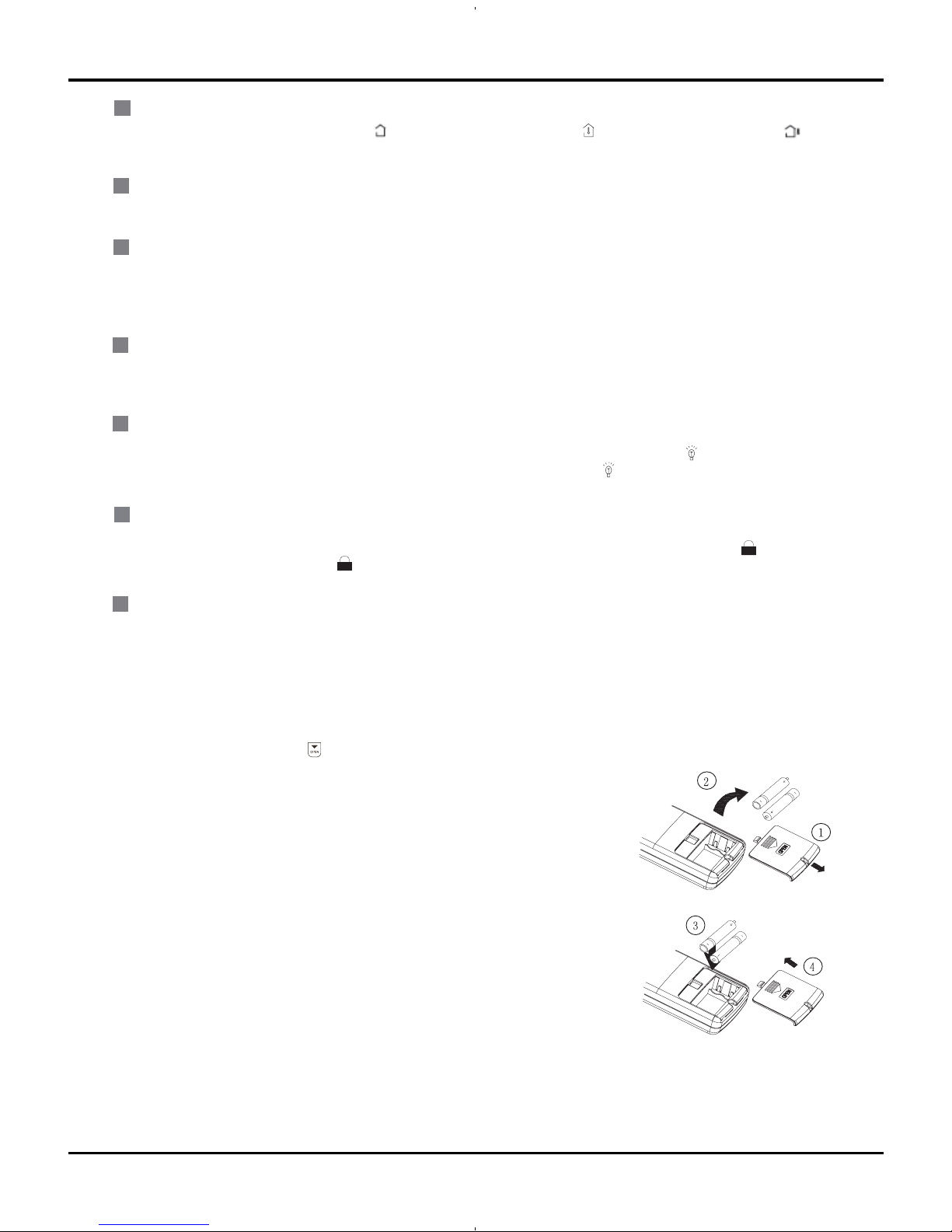
Sketch map for
replacing batteries
18
19
SLEEP:
LIGHT:
16
17
Press this button, Sleep On and Sleep Off can be selected. After Sleep function set up, the unit will automatically select
the suitable operation mode to maintain the most comfortable temperature for you. This function is available in COOL ,
HEAT or DRY mode
TURBO:
15
Press this button to activate / deactivate the Turbo function which enables the unit to reach the preset temperature in
shortest time. Such as in COOL mode, the unit will blow strong cooling air at super high fan speed. In HEAT mode, the
unit will blow strong heating air at super high fan speed.
(This function is not applicable for some models)
Press this button to select LIGHT on or off in the displayer. When the LIGHT on is set,the icon will be displayed and
the indicator light in the displayer will be on. When the LIGHT off is set, the icon will be displayed and the indicator
light in thedisplayer will be off.
"+" and "–"button about lock:
Press "+ " and "-" buttons simultaneously to lock or unlock the keypad. If the remote controller is locked, is displayed .
In this case, pressing any button , blinks three times.
"MODE" and " - " buttons About switch between fahrenheit and celsius:
At unit OFF, press "MODE" and " - " buttons simultaneously to switch between ℉ and ℃.
1.Slightly to press the place with , along the arrowhead direction to push the back
cover of wireless remote control. (As show in figure)
2. Take out the old batteries. (As show in figure)
3. Insert two new AAA1.5V dry batteries, and pay attention to the polarity.
(As show in figure)
4 .Attach the back cover of wireless remote control. (As show in figure)
TIMER OFF :
14
13
TEMP :
Once press this key to enter into TIMER OFF setup, in which case the TIMER OFF icon will blink.The method of setting
is the same as TIMER ON.
Press this button, could select displaying (the indoor setting temperature) , (indoor ambient temperature )or (
outdoor am-bient temperature) .The unit defaults not to display the icon. During operation of TEMP button, the set temperature is always displayed
6.2 Changing batteries and notices
17
6.3 Description of Each Control Operation
Function and Control
1. Temperature Parameters
Indoor preset temperature (Tpreset)
Indoor ambient temperature (T
amb.)
2. Basic Functions
Once energized, in no case should the compressor be restarted within less than 3 minutes. In the situation that memory function
is available, for the first energization, if the compressor is at stop before de-energization, the compressor will be started without
a 3-minute lag; if the compressor is in operation before de-energization, the compressor will be started with a 3-minute lag; and
once started, the compressor will not be stopped within 6 minutes regardless of changes in room temperature;
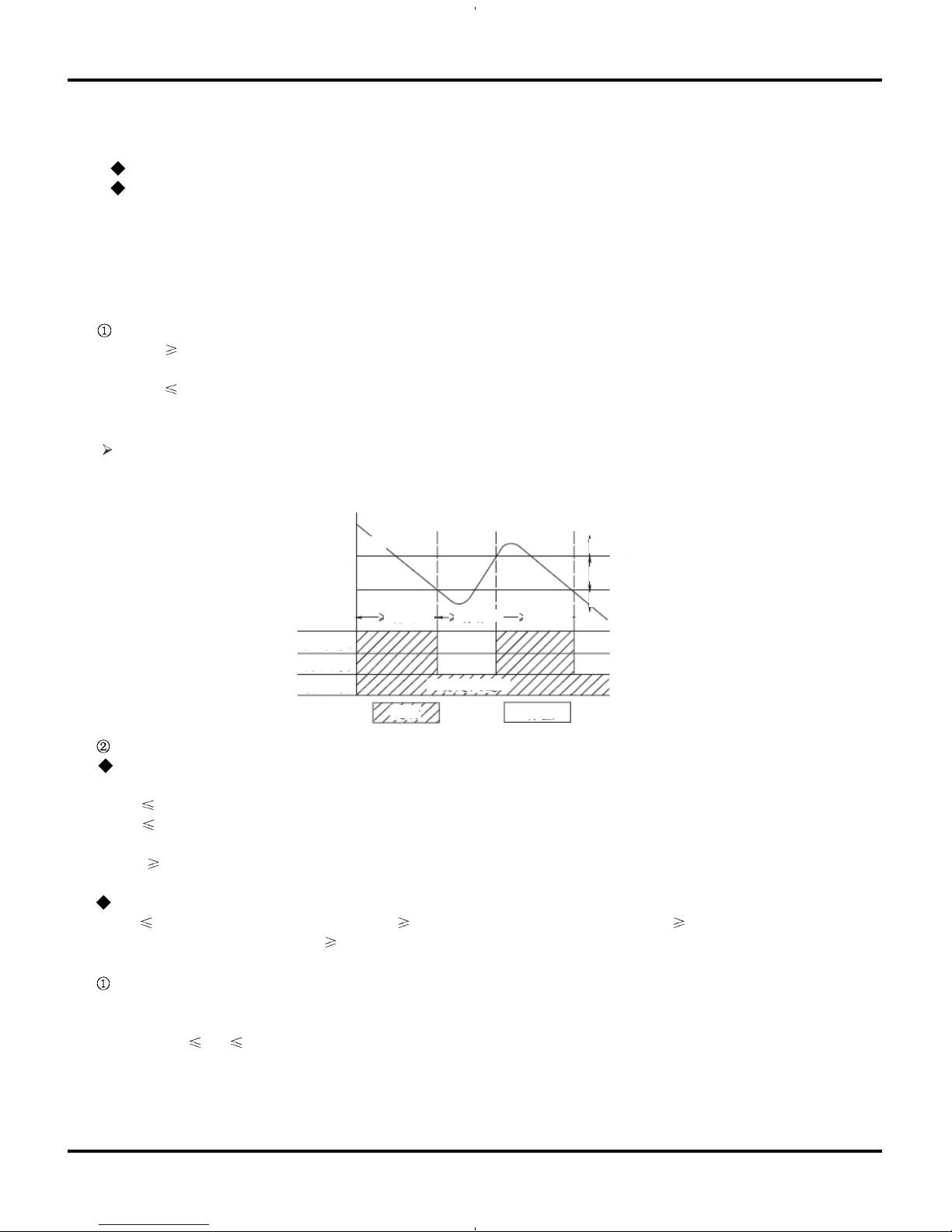
(1) Cooling Mode
Working conditions and process of cooling
When T
amb Tpreset, the unit will enter cooling operation, in which case the indoor fan, the outdoor fan and the compressor will
work and the indoor fan will run at preset speed.
When T
amb Tpreset -28.4 , the compressor will stop, the outdoor fan will stop with a time lag of 30s, and the indoor fan will run
at preset speed.
When T
preset -28.4 < Tamb.< Tpreset +33.8 , the unit will remain at its previous state.
Under this mode, the four-way valve will be de-energized and temperature can be set within a range from 61 to 86
If the compressor is shut down for some reason, the indoor fan and the swing device will operate at original state.
Start cooling
Stop cooling
Compressor
Original working state
Run
Stop
Outdoor fan
Indoor fan
T
preset
T
reset
28.4
T
amb
Preset fan speed
6 minutes
6 minutes
3 minutes
Protection
Antifreeze protection
Under cooling and dehumidifying mode, 6 minutes after the compressor is started:
If T
evap 35.6 , the compressor will operate at reduced frequency.
If T
evap 30.2 is detected for durative 3 minutes, the compressor will stop, and after 30 seconds, the outdoor fan will stop;
and under cooling mode, the indoor fan and the swing motor will remain at the original state.
If T
evap. 42.8 and the compressor has remained at OFF for at least 3 minutes, the compressor will resume its original
operation state.
Total current up and frequency down protection
If Itotal
A, frequency rise will be allowed; if Itotal B, frequency rise will not be allowed; ifItotal C, the compressor will
run at reduced frequency; and if Itotal
D, the compressor will stop and the outdoor fan will stop with a time lag of 30s.
(2) Dehumidifying Mode
Working conditions and process of dehumidifying
If T
amb>Tpreset, the unit will enter cooling and dehumidifying mode, in which case the compressor and the outdoor fan will
operate and the indoor fan will run at low speed.
If T
preset 28.4 Tamb Tpreset, the compressor remains at its original operation state.
If T
amb.< Tpreset 28.4 , the compressor will stop, the outdoor fan will stop with a time lag of 30s, and the indoor fan will
operate at low speed.
ºF
ºF
ºF
ºF
ºF
ºF
ºF
ºF
ºF
ºF
18
 Loading...