

Gree GWH09AAB-K6DNA3A, GWH12AAB-K6DNA3A, GWH09AAB-K6DNA3A/O, GWH12AAB-K6DNA3A/O Service Manual

GREE ELECTRIC APPLIANCES,INC.OF ZHUHAI
Change for Life
Service Manual
Models:
GWH09AAB-K6DNA3A
GWH12AAB-K6DNA3A
(Refrigerant R32)

Service Manual
Table of Contents
Part
Ⅰ
: Technical Information
.......................................................................1
1. Summary
......................................................................................................................1
2. Specications
..........................................................................................................2
2.1 Specication Sheet ...........................................................................................................2
2.2 Operation Characteristic Curve ........................................................................................4
2.3 Capacity Variation Ratio According to Temperature .........................................................4
2.4 Cooling and Heating Data Sheet in Rated Frequency .....................................................5
2.5 Noise Curve ......................................................................................................................5
3. Outline Dimension Diagram
........................................................................6
3.1 Indoor Unit ........................................................................................................................6
3.2 Outdoor Unit .....................................................................................................................7
4. Refrigerant System Diagram
......................................................................8
5. Electrical Part
...........................................................................................................9
5.1 Wiring Diagram .................................................................................................................9
5.2 PCB Printed Diagram ..................................................................................................... 11
6. Function and Control
......................................................................................13
6.1 Remote Controller Introduction .....................................................................................13
6.2 Operation of Smart Control (Smart Phone, Tablet PC) For Gree ...................................17
6.3 Operation of Smart Control (Smart Phone, Tablet PC) .................................................30
6.4 GREE+ App Operation Manual ......................................................................................43
6.5 Ewpe Smart App Operation Manual ...............................................................................44
6.6 Brief Description of Modes and Functions ......................................................................45
Part
Ⅱ
: Installation and Maintenance
.................................................51
7. Notes for Installation and Maintenance
..........................................51
8. Installation
................................................................................................................54
8.1 Installation Dimension Diagram ......................................................................................54
8.2 Installation Parts-Checking ............................................................................................56
8.3 Selection of Installation Location ....................................................................................56
8.4 Requirements for electric connection .............................................................................56
8.5 Installation of Indoor Unit ................................................................................................56
8.6 Installation of Outdoor unit .............................................................................................59
8.7 Vacuum Pumping and Leak Detection ...........................................................................60
8.8 Check after Installation and Test operation ....................................................................60
Table of Contents

Service Manual
9. Maintenance
............................................................................................................61
9.1 Error Code List ...............................................................................................................61
9.2 Procedure of Troubleshooting ........................................................................................69
9.3 Maintenance method for normal malfunction .................................................................85
10. Exploded View and Parts List
..............................................................87
10.1 Indoor Unit ....................................................................................................................87
10.2 Outdoor Unit .................................................................................................................89
11. Removal Procedure
.......................................................................................93
11.1 Removal Procedure of Indoor Unit ...............................................................................93
11.2 Removal Procedure of Outdoor Unit ............................................................................98
Appendix:
......................................................................................................................106
Appendix 1: Reference Sheet of Celsius and Fahrenheit ..................................................106
Appendix 2: Conguration of Connection Pipe ...................................................................106
Appendix 2: Pipe Expanding Method .................................................................................107
Appendix 4: List of Resistance for Temperature Sensor ....................................................108
Table of Contents
1
Technical Information
Service Manual
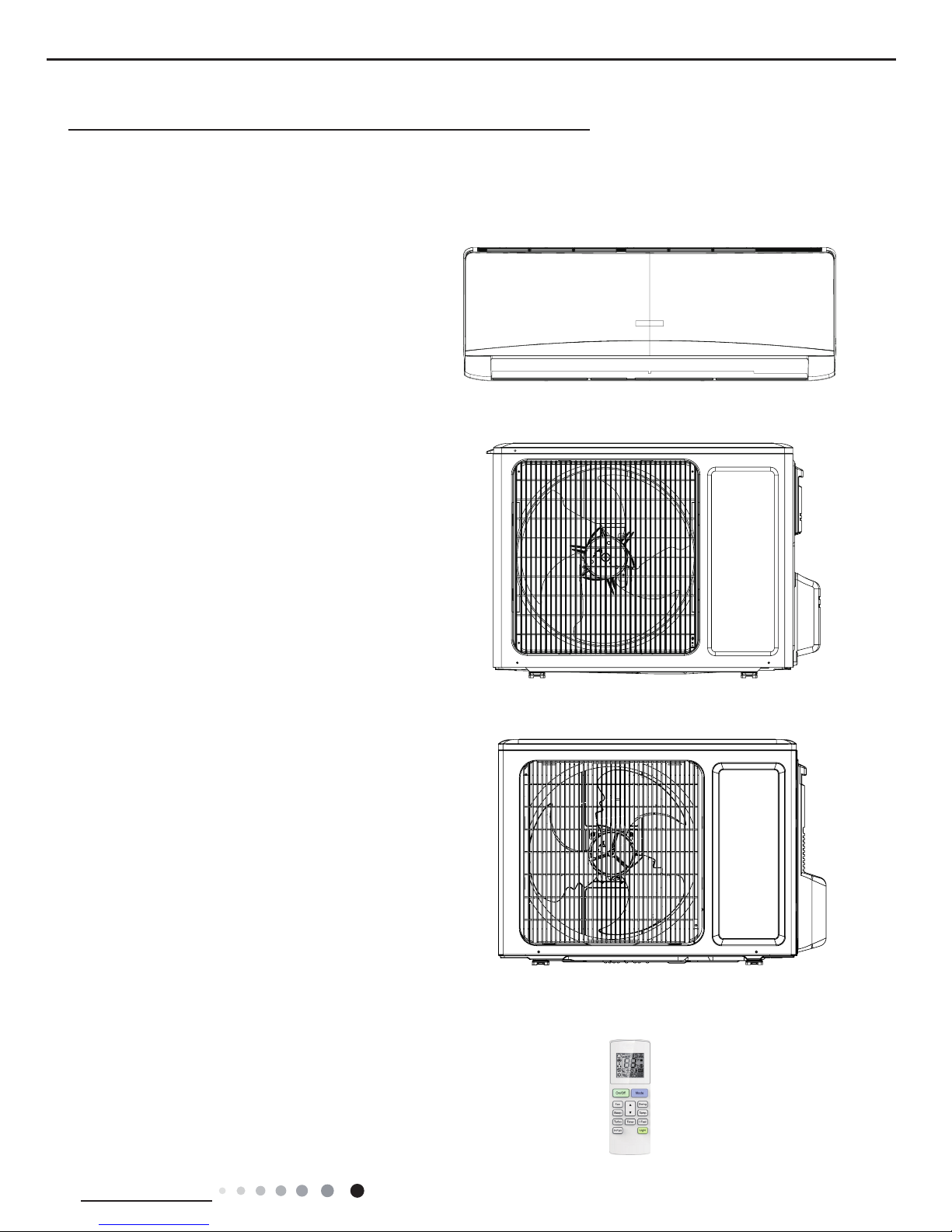
1. Summary
Indoor Unit:
GWH09AAB-K6DNA3A/I
GWH12AAB-K6DNA3A/I
Part
Ⅰ
: Technical Information
Outdoor Unit:
GWH12AAB-K6DNA3A/O(LC)
GWH09AAB-K6DNA3A/O(LC)
Remote Controller:
YAW1F
2
Technical Information
Service Manual
2. Specications
2.1 Specication Sheet
Model GWH09AAB-K6DNA3A GWH12AAB-K6DNA3A
Product Code CB478000200 CB478000100
Power
Supply
Rated Voltage V~ 220-240 220-240
Rated Frequency Hz 50 50
Phases 1 1
Power Supply Mode Outdoor Outdoor
Cooling Capacity W 2500 3200
Heating Capacity W 2800 3400
Cooling Power Input W 781 997
Heating Power Input W 777 941
Cooling Power Current A 3.99 4.5
Heating Power Current A 3.74 4.4
Rated Input W 1500 1500
Rated Current A 6.9 7.2
Air Flow Volume(SH/H/M/L/SL) m3/h 550/500/430/300/- 550/480/410/290/-
Dehumidifying Volume
L/h
0.8 1.4
EER W/W
3.20
3.21
COP
W/W 3.60
3.61
SEER W/W 6.1 6.1
HSPF W/W / /
Application Area m
2
12-18 16-24
Indoor Unit
Model of Indoor Unit GWH09AAB-K6DNA3A/I GWH12AAB-K6DNA3A/I
Product Code of Indoor Unit CB478N00200 CB478N00100
Fan Type Cross-ow Cross-ow
Diameter Length(DXL) mm Ф93X580 Φ93X580
Fan Motor Cooling Speed(SH/H/M/L/SL) r/min 1300/1200/1100/850/- 1350/1200/1100/850/-
Fan Motor Heating Speed(SH/H/M/L/SL) r/min 1250/1150/1050/900/- 1350/1200/1100/900/-
Output of Fan Motor W 20 20
Fan Motor RLA A 0.22 0.22
Fan Motor Capacitor μF 1 1
Input of Heater W
/
/
Evaporator Form Aluminum Fin-copper Tube Aluminum Fin-copper Tube
Pipe Diameter mm Φ5 Φ5
Row-n Gap mm 2-1.4 2-1.4
Coil Length (LXDXW) mm 584X22.8X266.7 584X22.8X266.7
Swing Motor Model MP24AN MP24AN
Output of Swing Motor W 1.5 1.5
Fuse A 3.15 3.15
Sound Pressure Level (SH/H/M/L/SL) dB (A) 40/37/35/28/- 42/37/34/28/-
Sound Power Level (SH/H/M/L/SL) dB (A) 55/49/47/40/- 55/49/46/40/-
Dimension (WXHXD) mm 773X250X185 773X250X190
Dimension of Carton Box (LXWXH) mm 817X306X244 817X306X244
Dimension of Package (LXWXH) mm 822X322X255 822X322X255
Net Weight kg 8.5 8.5
Gross Weight kg 9.5 9.5
3
Technical Information
Service Manual
The above data is subject to change without notice; please refer to the nameplate of the unit.
Outdoor Unit
Model of Outdoor Unit GWH09AAB-K6DNA3A/O GWH12AAB-K6DNA3A/O (LC)
Product Code of Outdoor Unit CB478W00200 CB478W00100
Compressor Manufacturer/Trademark
ZHUHAI LANDA COMPRESSOR
CO.,LTD
ZHUHAI LANDA COMPRESSOR
CO., LTD
Compressor Model QXF-B096zE190A QXF-B096zE190A
Compressor Oil FW68DA FW68DA
Compressor Type Rotary Rotary
L.R.A. A 20 20
Compressor RLA A 4.21 4.21
Compressor Power Input W 943 943
Overload Protector
1NT11L-6233 HPC115/95U1
KSD115
℃
1NT11L-6233 HPC115/95U1
KSD115℃
Throttling Method Capillary Capillary
Operation Temp
o
C 16~30 16~30
Ambient Temp (Cooling)
o
C -15~43 -15~43
Ambient Temp (Heating)
o
C -15~24 -15~24
Condenser Form Aluminum Fin-copper Tube Aluminum Fin-copper Tube
Pipe Diameter mm Φ7 Φ7.94
Rows-n Gap
mm
1-1.4
1-1.4
Coil Length (LXDXW) mm 710X19.05X508 731X19.05X550
Fan Motor Speed rpm 900 900
Output of Fan Motor W 30 30
Fan Motor RLA A 0.36 0.36
Fan Motor Capacitor μF / /
Air Flow Volume of Outdoor Unit m3/h 1600 2200
Fan Type Axial-ow Axial-ow
Fan Diameter mm Φ400 Φ438
Defrosting Method Automatic Defrosting Automatic Defrosting
Climate Type T1 T1
Isolation I I
Moisture Protection IPX4 IPX4
Permissible Excessive Operating Pressure for
the Discharge Side
MPa 4.3 4.3
Permissible Excessive Operating Pressure for
the Suction Side
MPa 2.5 2.5
Sound Pressure Level (H/M/L) dB (A) 52/-/- 52/-/-
Sound Power Level (H/M/L) dB (A) 60/-/- 62/-/-
Dimension (WXHXD) mm 782X540X320 842X596X320
Dimension of Carton Box (LXWXH) mm 820X355X580 878X360X630
Dimension of Package (LXWXH) mm 823X358X595 881X363X645
Net Weight kg 29 31
Gross Weight kg 31.5 34
Refrigerant R32 R32
Refrigerant Charge kg 0.6 0.65
Connection
Pipe
Length m 5 5
Gas Additional Charge g/m 20 20
Outer Diameter Liquid Pipe mm Φ6 Φ6
Outer Diameter Gas Pipe mm Φ9.52 Φ9.52
Max Distance Height m 10 10
Max Distance Length m 15 20
Note: The connection pipe applies metric diameter.
4
Technical Information
Service Manual
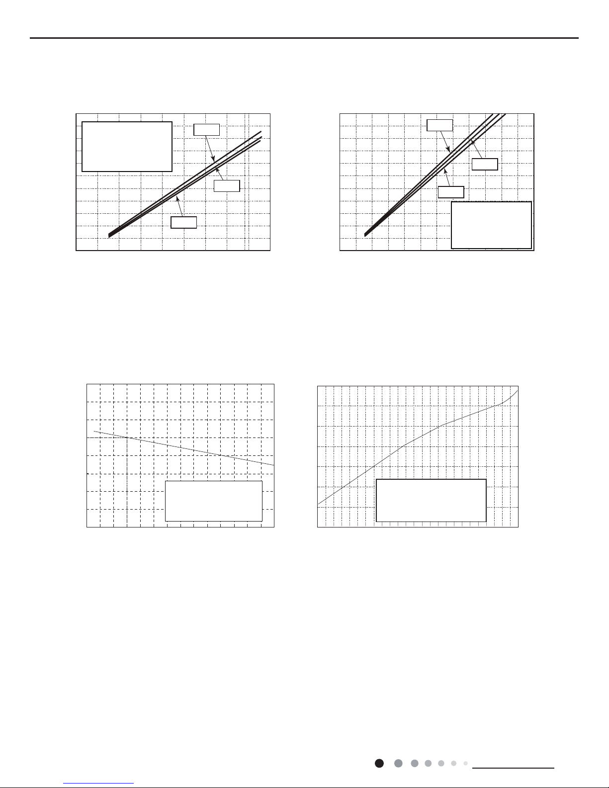
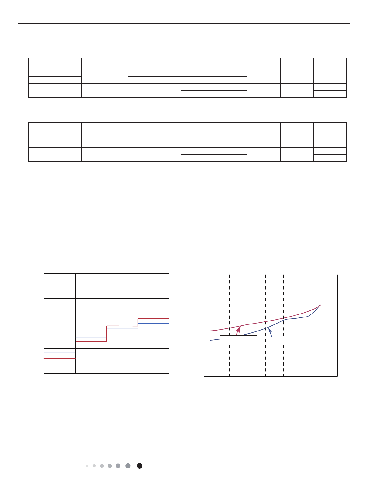
2.2 Operation Characteristic Curve
2.3 Capacity Variation Ratio According to Temperature
Compressor Speed(rps)
Compressor Speed(rps)
Cooling
Heating
Current(A)
Current(A)
50
60
70
80
90
100
110
120
130
32 33 34 35 36 37 38 39 40 41 42 43 44 45 46
Capacity ratio(%)
Outdoor temp. (°C)
Capacity ratio(%)
gnitaeHgnilooC
gnitaeHgnilooC
-20-15 -10-50 510
110
120
130
100
90
80
70
60
50
40
Outdoor temp.(°C)
0
1
2
3
4
5
6
7
8
9
10
020406080100 120
WB19
°C
0
1
2
3
4
5
6
7
8
020406080 100
120
50
60
70
80
90
100
110
120
130
32 33 34 35 36 37 38 39 40 41 42 43 44 45 46
Capacity ratio(%)
Outdoor temp. (°C)
Capacity ratio(
%)
–15 –10 –5
110
100
90
80
70
60
50
40
05
71
0
Conditions
Indoor:DB20°C
Indoor air flow:Super High
Pipe length:5m
Outdoor temp.(°C)
Condition
Indoor:DB27°C WB19°C
Indoor air flow:
High
Pipe length:5m
Condition
Indoor:DB27°C WB19°C
Indoor air flow:
High
Pipe length:5m
Condition
Indoor:DB20°C
Indoor air flow:
High
Pipe length:5m
Condition
Indoor:DB 27°C
Indoor air flow: Super High
Pipe length:5m
Voltage:230V
Condition
Indoor:DB 20°C
Indoor air flow: Super High
Pipe length:5m
Voltage:230V
Heating operation ambient temperature range is -15ºC~24ºC
01020304050607090010 20 30 40 50 60 70 80 90 100 120 110
80
11
10
9
8
7
6
5
4
3
2
1
0
Compressor speed (rps)
) A ( t n e r r u C
11
10
9
8
7
6
5
4
3
2
1
0
Compressor speed (rps)
) A ( t n e r r u C
220V
230V
240V
220V
230V
240V
01020304050607090010 20 30 40 50 60 70 80 90 100
120
110
80
11
10
9
8
7
6
5
4
3
2
1
0
Compressor speed (rps)
)A(tnerruC
11
10
9
8
7
6
5
4
3
2
1
0
Compressor speed (rps)
)A(tnerruC
220V
230V
240V
220V
230V
240V
Conditions
Indoor: DB27°C/WB19°C
Outdoor: DB35°C/WB24°C
Indoor air flow: High
Pipe length: 5m
Conditions
Indoor: DB27°C/WB19°C
Outdoor: DB35°C/WB24°C
Indoor air flow: High
Pipe length: 5m
Conditions
Indoor: DB20°C/WB15°C
Outdoor: DB7°C/WB6°C
Indoor air flow: High
Pipe length: 5m
Conditions
Indoor: DB20°C/WB15°C
Outdoor: DB7°C/WB6°C
Indoor air flow: High
Pipe length: 5m
Cooling Heating
5
Technical Information
Service Manual
2.4 Cooling and Heating Data Sheet in Rated Frequency
2.5 Noise Curve
Indoor side noise when blowing
Indoor fan motor rotating speed
Noise/dB(A)
50
60
30
40
20
Low
Middle
High
Super High
Outdoor side noise when blowing
Compressor frequency(Hz)
40
42
44
46
48
50
52
54
56
20 03045060708
09
0
Noise dB(A)
09&12K Cooling
09&12K Heating
Cooling:
Rated cooling
condition(°C) (DB/WB)
Model
Pressure of gas pipe
connecting indoor and
outdoor unit
Inlet and outlet pipe
temperature of heat
exchanger
Fan speed of
indoor unit
Fan speed of
outdoor unit
Compressor
revolution
(rps)
Indoor Outdoor P (MPa) T1 (°C) T2 (°C)
27/19 35/24 09/12K 0.8 ~ 1.1
12 to 15 65 to 38
TURBO High
49
11 to 14 64 to 37 60
Instruction:
T1: Inlet and outlet pipe temperature of evaporator
T2: Inlet and outlet pipe temperature of condenser
P: Pressure at the side of big valve
Connection pipe length: 5 m.
Heating:
Rated cooling
condition(°C) (DB/WB)
Model
Pressure of gas pipe
connecting indoor and
outdoor unit
Inlet and outlet pipe
temperature of heat
exchanger
Fan speed of
indoor unit
Fan speed of
outdoor unit
Compressor
revolution
(rps)
Indoor Outdoor P (MPa) T1 (°C) T2 (°C)
20/- 7/6 09/12K 2.8 ~ 3.2
35 to 63 2 to 5
TURBO High
59
35 to 65 2 to 5 67
6
Technical Information
Service Manual
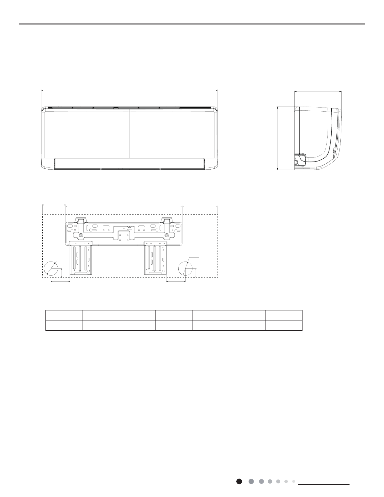
3. Outline Dimension Diagram
3.1 Indoor Unit
Unit:mm
Models W H D W1 W2 W3
09/12K 773 250 185 131 462 180
D
H
W
75
35
Φ55
W3W2
W1
Φ55
35
75
7
Technical Information
Service Manual
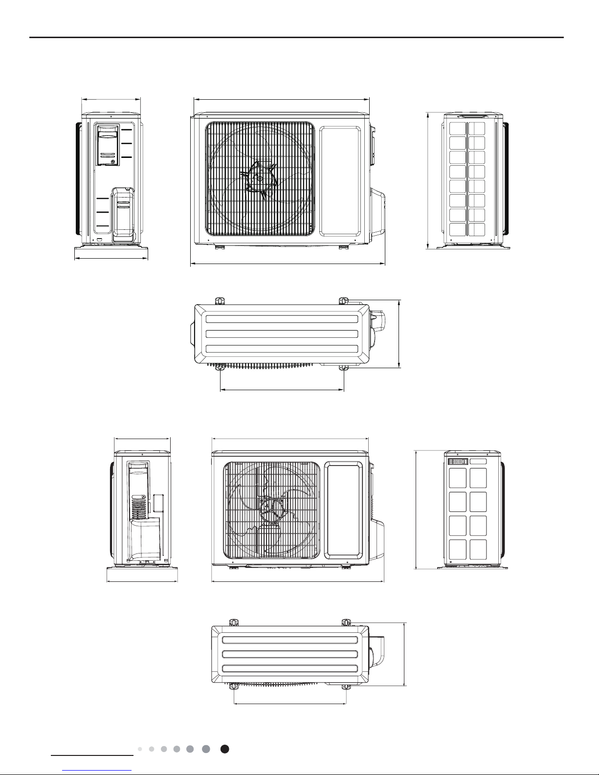
3.2 Outdoor Unit
257
780
596
842
286
540
320
Unit:mm
09K
12K
Unit:mm
320
782
510
712257
286
540
8
Technical Information
Service Manual
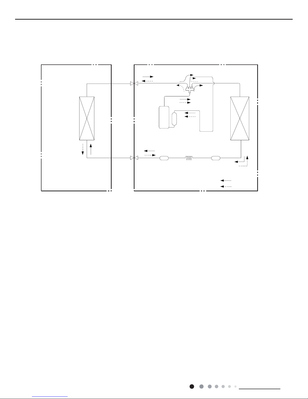
4. Refrigerant System Diagram
Cooling and heating model
Connection pipe specication:
Liquid pipe:1/4" (6mm)
Gas pipe:3/8" (9.52mm)
Indoor unit
Outdoor unit
Indoor unit
Outdoor unit
COOLING
HEATING
Accumlator
4-Way valve
COOLING
Discharge
Suction
Discharge
Suction
Heat
exchanger
(evaporator)
Heat
exchanger
(evaporator)
Heat
exchanger
(condenser)
Heat
exchanger
(condenser)
Valve
Valve
Valve
Valve
Liquid pipe
side
Gas pipe
side
Liquid pipe
side
Gas pipe
side
Compressor
Accumlator
Compressor
Strainer
Strainer
Capillary
StrainerCapillary
9
Technical Information
Service Manual
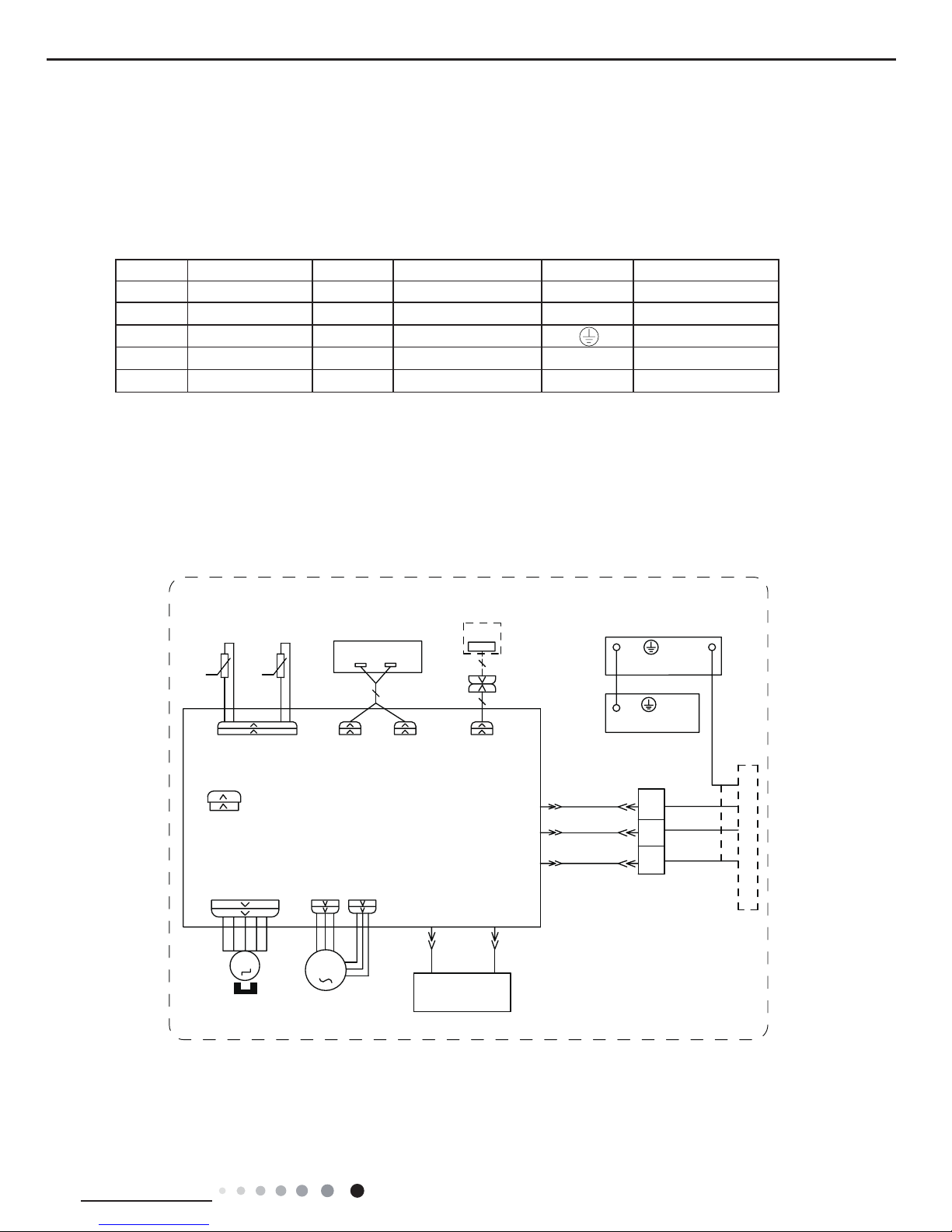
Symbol Symbol Color Symbol Symbol Color Symbol Name
WH White GN Green CAP Jumper cap
YE Yellow BN Brown COMP Compressor
RD Red BU Blue Grounding wire
YEGN Yellow/Green BK Black / /
VT Violet OG Orange / /
5. Electrical Part
5.1 Wiring Diagram
● Indoor Unit
●Instruction
Note: Jumper cap is used to determine fan speed and the swing angle of horizontal lover for this model.
600007000973
76(1625
7(03
6(1625
7(03
6(1625
57
522078%(
67(33,1*
',63/$<
35,17('&,5&8,7%2$5'
5(&(,9(5$1'
',63/$<%2$5'
&$%/(
&211(&7,1*
6:,1*8'
02725
%/2&.
7(50,1$/
$3
-803
&$3
%8
%.
<(*1
;7
1
0
287'22581,7
$3
3*
*(1(5$725
&2/'3/$60$
)$102725
0
5' %8
+($/7+1
+($/7+/
3*)
',63 ',63
%1
57
1
&20287
$&/
%8
%.
%1
:,),
02'8/(
:,),
$3
3(
($57+3/$7(
<(*1
3(
(9$325$725
10
Technical Information
Service Manual
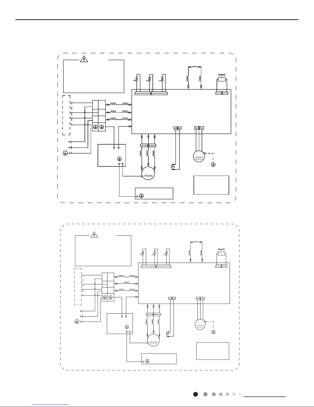
● Outdoor Unit
These wiring diagrams are subject to change without notice; please refer to the one supplied with the unit.
RIHOHFWULFVKRFN
3OHDVHGRQWWRXFKDQ\
WHUPLQDOZKHQWKHPDFKLQHLV
UXQQLQJVWRSSLQJRUKDVEHHQ
SRZHUHGRIIIRUOHVVWKDQ
PLQXWHVWRSUHYHQWWKHULVN
:$51,1*
<(*1
%8
%.
%1
1
/
1
/
/
/
/
%8
%1
0$*1(7,&5,1*
7(50,1$/
;7
%/2&.
1
$&/$&/
&208
3(
&1
7(03
6(1625
7(03
6(1625
7(03
57
57
57
6(1625
N
N
N
28778%(
2875220
(;+$867
<9
:$<
:$<
9$/9(
97
97
/;
/;
/
/
5($&725
/
%8
%1
0$*1(7,&
5,1*
$30DLQ%RDUG
2)$1
)$1
0
3(
3(
<(*1
02725
3527(&725
29(5/2$'
5'
29&&203
6$7
5'
/
:
9
8
&203
&203
:
9
8
;
%8
<(
5'
0$*1(7,&
5,1*
32:(5
/
1
<(*1
%8
%1%.
<(*1
<(*1
3(
<(*1
(/(&75,&$/
%2;
3(
0,',62/$7,21
6+((7
3(
<(*1
%8
<(
5'
/
/
%.
127(0RWRU
DSSOLHVWRWKH
LURQVKHOOPRWRU
JURXQGRQO\
,1'22581,7
600007000763
600007000687
09K
12K
RIHOHFWULFVKRFN
3OHDVHGRQWWRXFKDQ\
WHUPLQDOZKHQWKHPDFKLQHLV
UXQQLQJVWRSSLQJRUKDVEHHQ
SRZHUHGRIIIRUOHVVWKDQ
PLQXWHVWRSUHYHQWWKHULVN
:$51,1*
<(*1
%8
%.
%1
1
/
1
/
/
/
/
%8
%.
%1
0$*1(7,&5,1*
7(50,1$/
;7
%/2&.
1
$&/
&208
3(
&1
7(03
6(1625
7(03
6(1625
7(03
57
57
57
6(1625
N
N
N
28778%(
2875220
(;+$867
<9
:$<
:$<
9$/9(
97
97
/;/;
/
/
5($&725
/
%8
%1
0$*1(7,&
5,1*
$30DLQ%RDUG
2)$1
)$1
0
3(
3(
<(*1
02725
3527(&725
29(5/2$'
5'
29&&203
6$7
5'
/
:
9
8
&203
&203
:
9
8
;
%8
<(
5'
0$*1(7,&
5,1*
32:(5
/
1
<(*1
%8
%1%.
<(*1
<(*1
3(
<(*1
(/(&75,&$/
%2;
3(
0,',62/$7,21
6+((7
3(
<(*1
%8
<(
5'
127(0RWRU
DSSOLHVWRWKH
LURQVKHOOPRWRU
JURXQGRQO\
,1'22581,7
/
11
Technical Information
Service Manual
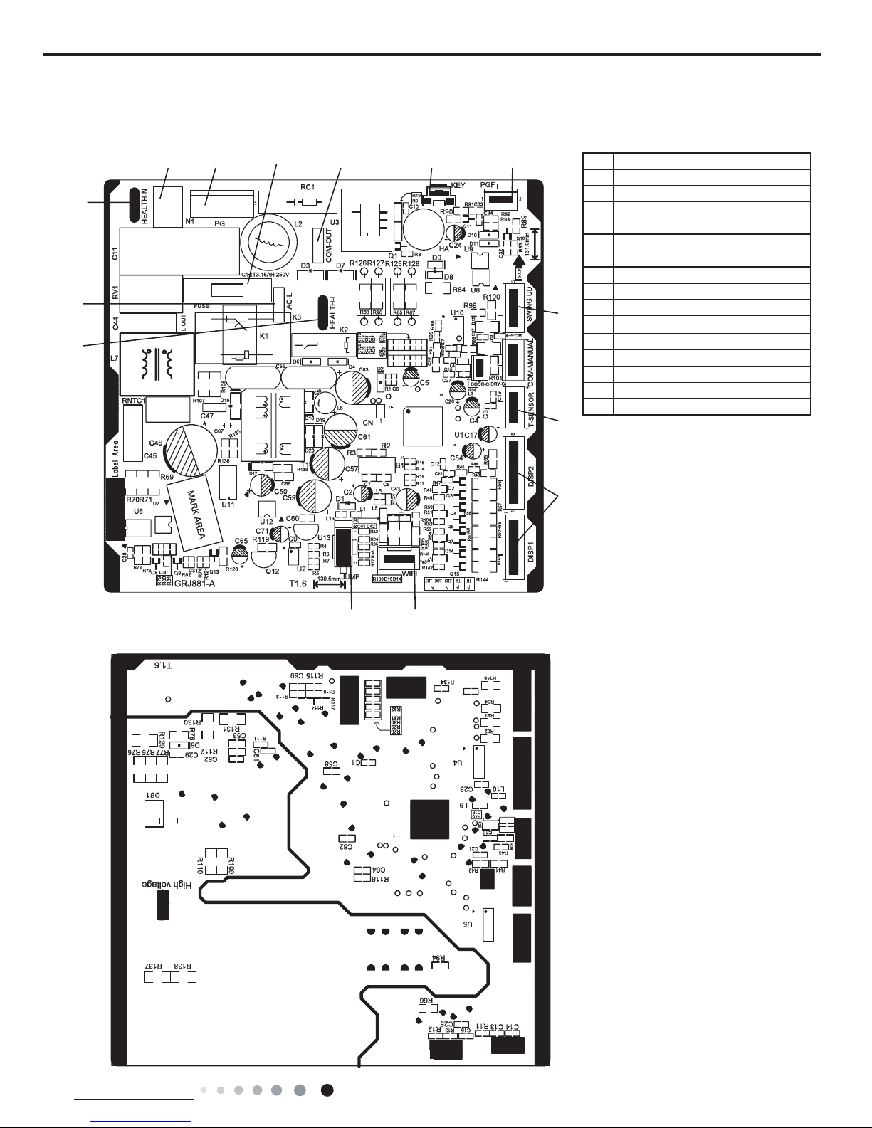
5.2 PCB Printed Diagram
● Top view
● Bottom view
1
2
14
13
12
11
109
876
5
4
3
No. Name
1 Wi interface
2 Jumper cap
3 Interface of health function live wire
4 Live wire interface
5
Interface of health function neutral
wire
6 Neutral wire interface
7 Fan motor interface of PG
8 Fuse
9 Communication interface
10 Auto button
11 Interface of PG feedback interface
12 Swing interface
13 Interface of temperature sensor
14 Display interface
Indoor Unit
12
Technical Information
Service Manual
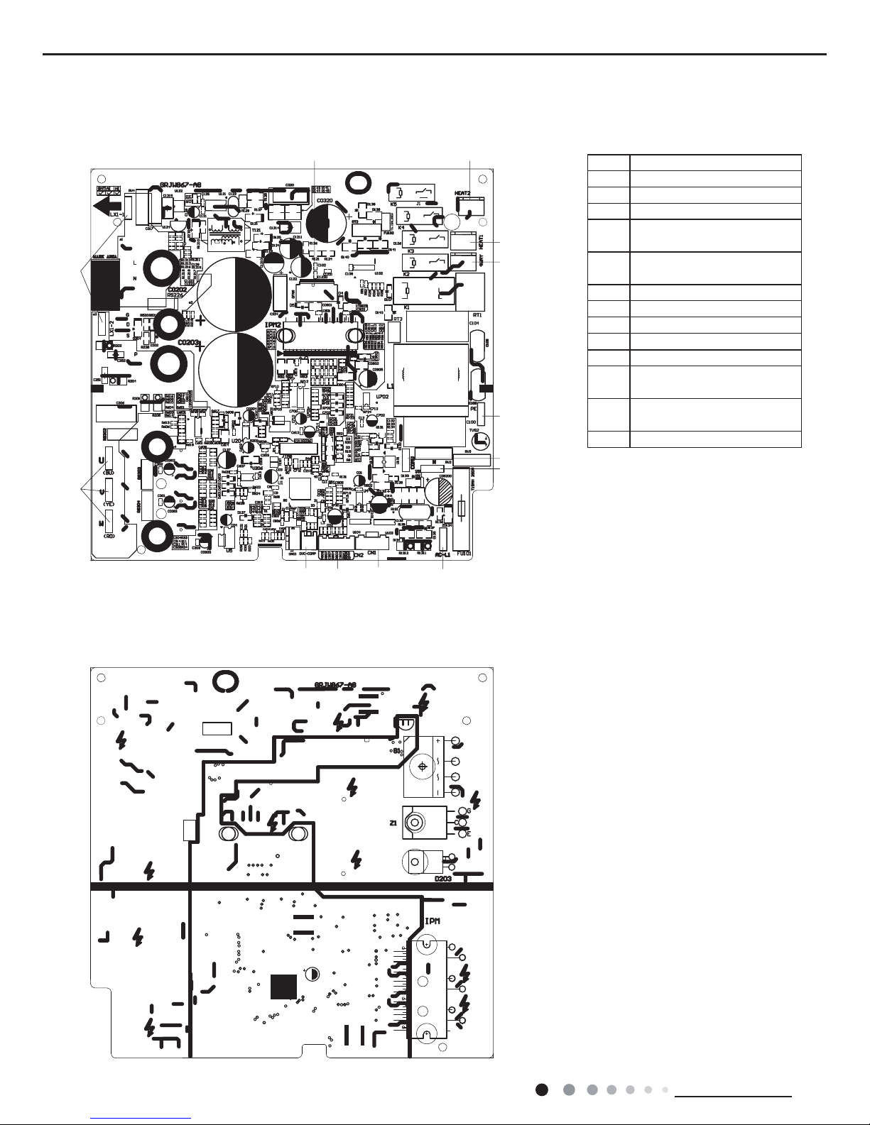
● Top view
● Bottom view
1
2
3 4
5
6
7
8
9
10111213
Outdoor Unit
No. Name
1 Compressor wiring terminal
2 Reactor wiring terminal
3 Outdoor fan wiring terminal
4
Terminal of chassis electric
heater
5
Terminal of compressor
electric heater
6 Terminal of 4-way valve
7 Grounding wire
8 Communication wire
9
Neutral wire
10 Live wire
11
Terminal of electronic
expansion valve
12
Terminal of temperature
sensor
13 Compressor overload terminal
13
Technical Information
Service Manual
6. Function and Control
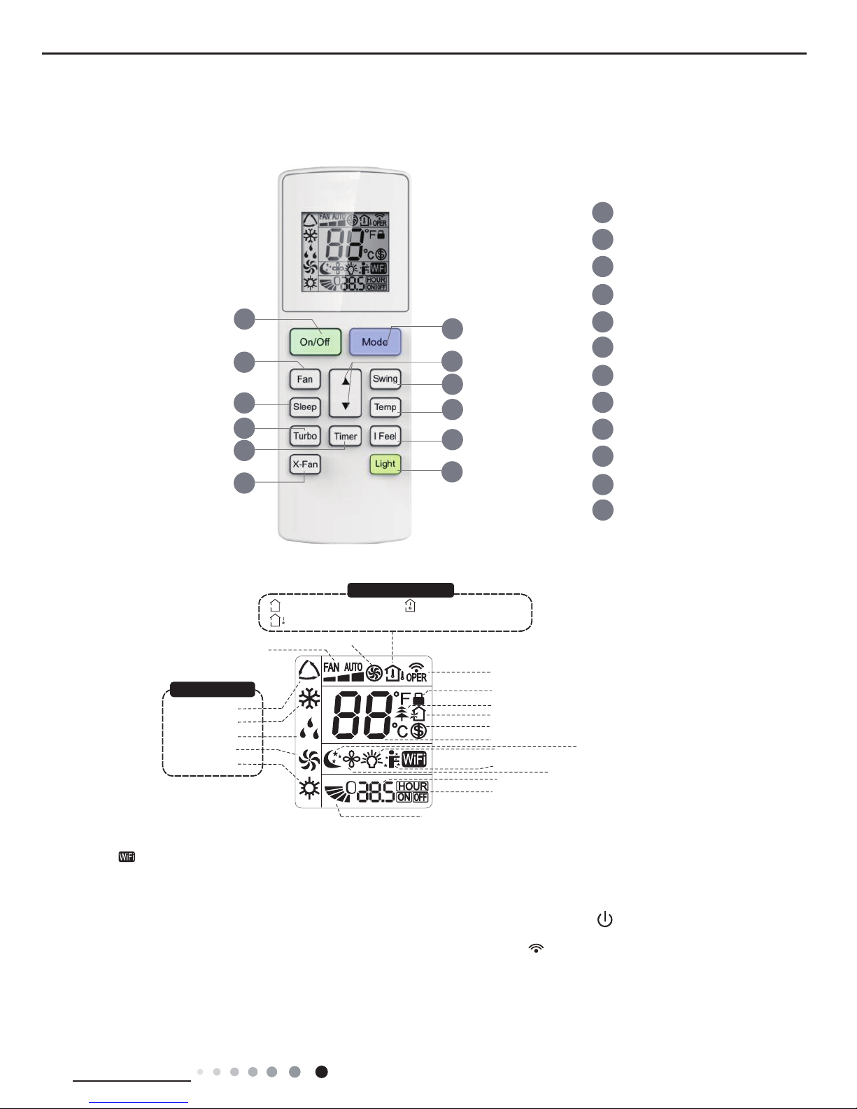
6.1 Remote Controller Introduction
Icon Display on Remote Controller
Operation introduction of remote controller
Buttons on Remote Controller
Note:
1
2
5
4
6
7
8
11
12
9
On/Off button
▲/ button
3
Fan button
Swing button
X-Fan button
Turbo button
Light button
10
Temp button
I Feel button
Timer button
Sleep button
Mode button
▲
2
5
7
9
4
12
3
1
6
8
10
11
Send signal
Turbo mode
8ć heating function
Set temperature
Set time
TIMER ON /TIMER OFF
Child lock
Up & down swing
Set fan speed
Light function
Temp. display type
:Set temp.
:Outdoor ambient temp.
:Indoor ambient temp.
Sleep mode
Heat mode
Fan mode
Dry mode
Cool mode
Auto mode
Operation mode
I feel function
X-fan mode
health function
ventilation operation
“ ” This is a general remote controller. Some models have this function while some do not. Please refer to the
actual models.
● This is a general use remote controller, it could be used for the air conditioners with multifunction; For some function, wh
ich
the model doesn't have, if press the corresponding button on the remote controller that the unit will keep the original running status.
●After putting through the power, the air conditioner will give out a sound.Operation indictor " " is ON (red indicator). After that,
you can operate the air conditioner by using remote controller.
● Under on status, pressing the button on the remote controller, the signal icon " "on the display of remote controller wi
ll
blink once and the air conditioner will give out a “de” sound, which means the signal has been sent to the air conditioner
.
● Under off status, set temperature and clock icon will be displayed on the display of remote controller (If timer on, timer off and
light functions are set, the corresponding icons will be displayed on the display of remote controller at the same time); Under on
status, the display will show the corresponding set function icons
.
14
Technical Information
Service Manual
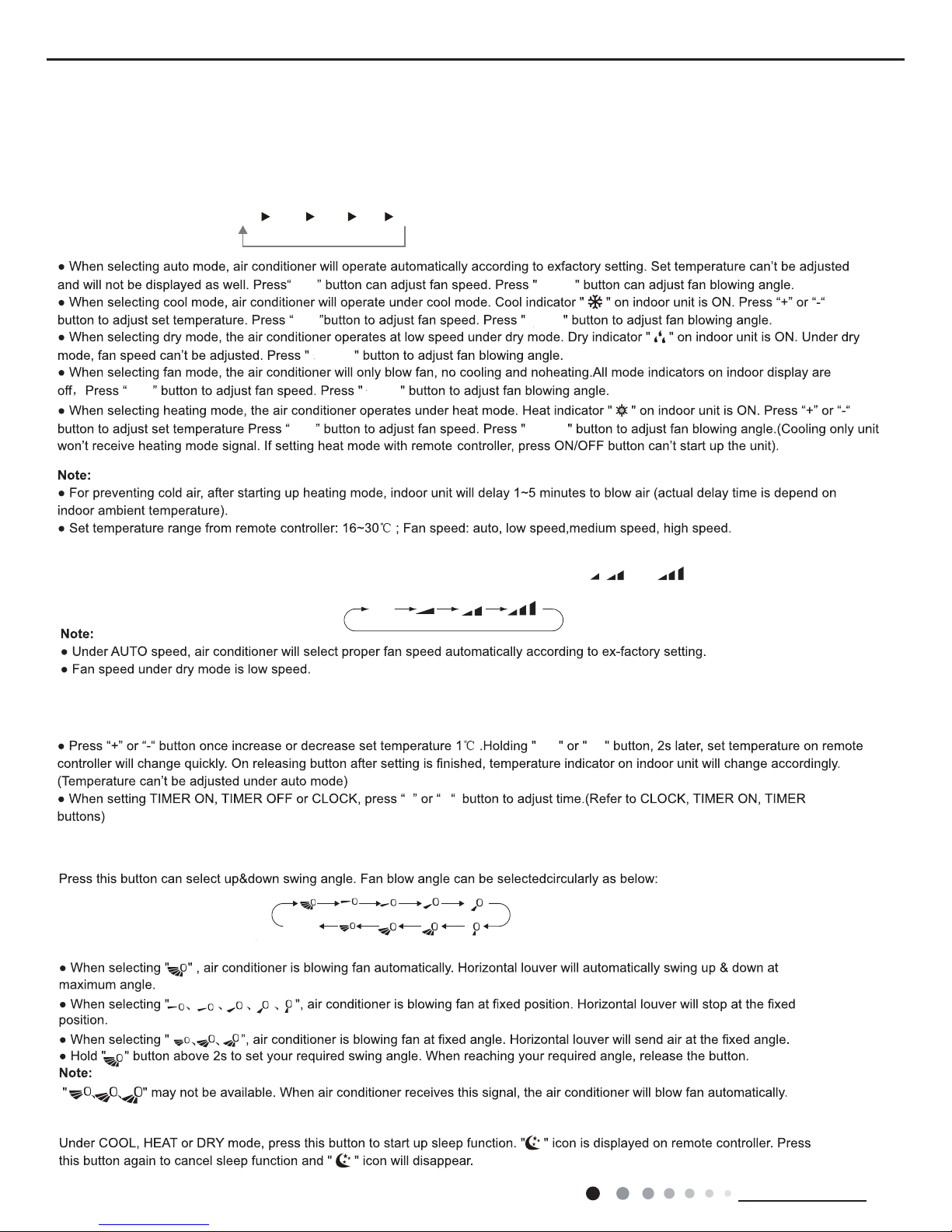
1. ON/OFF button
2. MODE button
3. F
AN button
6. SLEEP button
5. SWING button
Press this button to turn on the unit. Press this button again to turn off the unit.
Each time you press this button,a mode is selected in a sequence that goes from AUTO, COOL, DRY, FAN, and HEAT *,
as the following:
AUTO COOL DRY FAN
HEAT
*
* Note: Only for models with heating function.
This button is used for setting Fan Speed in the sequence that goes from AUTO,
, to , then back to Auto.
4.▲ / button
▲
▲Press / button to increase/decreaseset temperature.In AUTO mode,set temperature is not adjustable.
▲
Press this button to set up & down swing angle.
Auto
OFF
▲
▲
▲
▲
(horizontal louvers
stops at current position)
no display
Fan
Fan
Swing
Swing
Swing
Swing
Swing
Fan
Fan
15
Technical Information
Service Manual
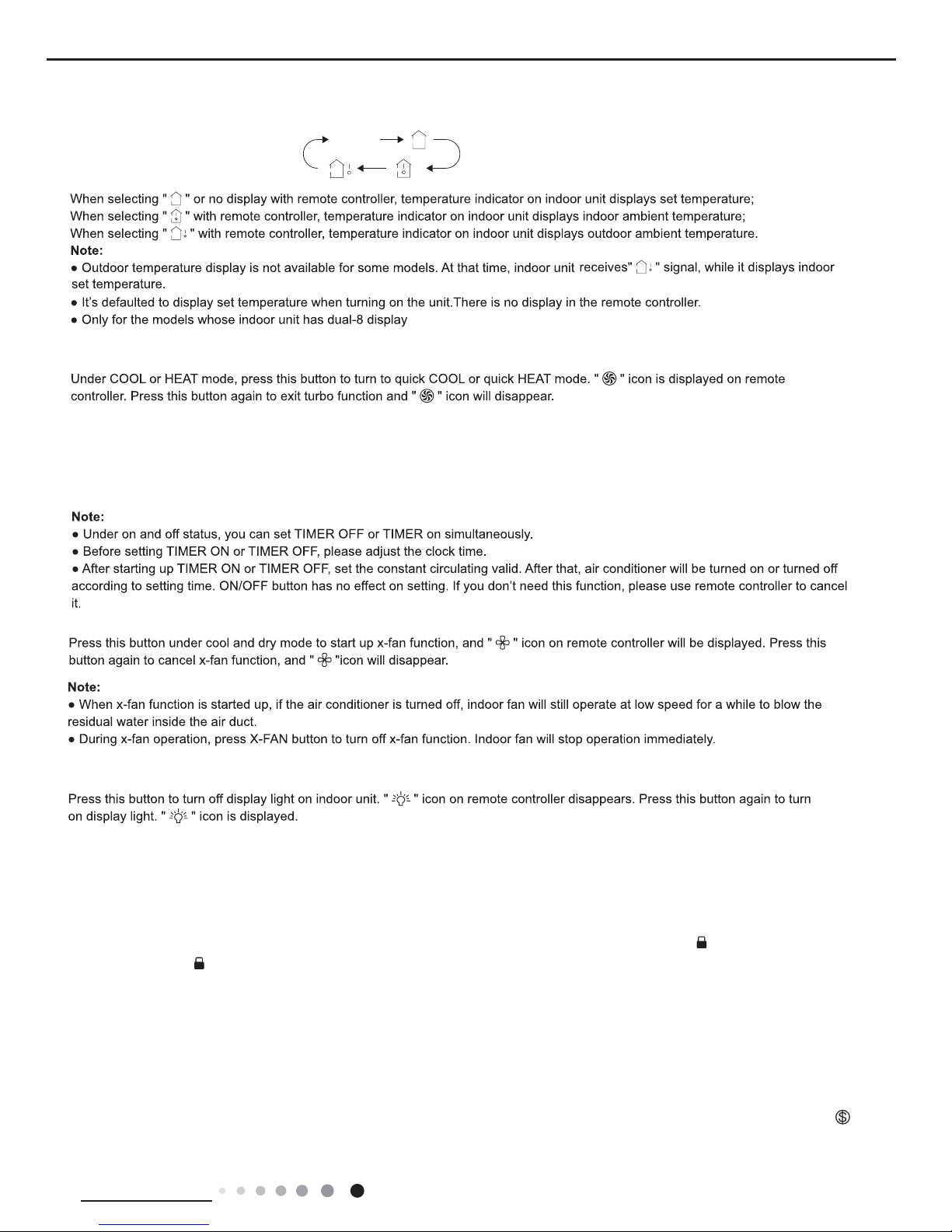
7. TEMP button
8. TURBO button
9. I FEEL button
10. Timer button
11. X-FAN button
12. LIGHT button
NOTICE:
Press this button, you can see indoor set temperature, indoor ambient temperature
on indoor unit’s display. The setting
on remote controller is selected circularly as below:
no display
Press this button to activate / deactivate the Turbo function.
Press this button to turn on I FEEL function.
Under ON status, press this button to set timer OFF; Under OFF status, press this button to set timer ON.
Turn on the display's light and press this button again to turn off the display's
light.
As for the detailed content of remote controller, please refer to QR code on the cover.
Function introduction for combination buttons
Press " " and " "
buttons simultaneously 3s to lock or unlock the keypad. If the remote
pressing any button, blinks three times.
controller is locked, is displayed. In this case,
▲
Combination of "" and " " buttons: About lock
▲
▲
▲
About switch between Fahrenheit and centigradeCombination of "MODE" and " " buttons:
▲
At unit OFF, press "MODE" and " " buttons simultaneously to
switch between ć and .
▲
Nixie tube on the remote controller displays
"SE"
. Repeat the operation to quit the function.
Combination of "TEMP" and "TIMER" buttons: About Energy-saving Function
Press "TEMP" and "TIMER" simultaneously in COOL mode to start energy-saving function.
(46 if Fahrenheit is adopted). Repeat the operation to quit the function.
Combination of "TEMP" and "TIMER" buttons:
About 8
ć
Heating Function
Press "TEMP" and "
TIMER
" simultaneously in HEAT mode to start 8ć Heating Function
Nixie tube on the remote controller displays "
"
and a selected temperature of
"8ć".
(NOTE:X-FAN is the alternative expression of BLOW for the purpose of understanding.)
16
Technical Information
Service Manual
WIFI Function
Press this button to turn on the unit. Press this button again to turn off the unit. Press "MODE" and "TURBO" button simultaneously to
and "TURBO" buttons simultaneously for
10s, remote controller will send WIFI reset code and then the WIFI function will be turned on.
WIFI function is defaulted ON after energization of the remote controller.
turn on or turn off WIFI function. When WIFI function is turned on, the " " icon will be displayed on remote controller
; Long press "MODE"
● This function is only available for some models.
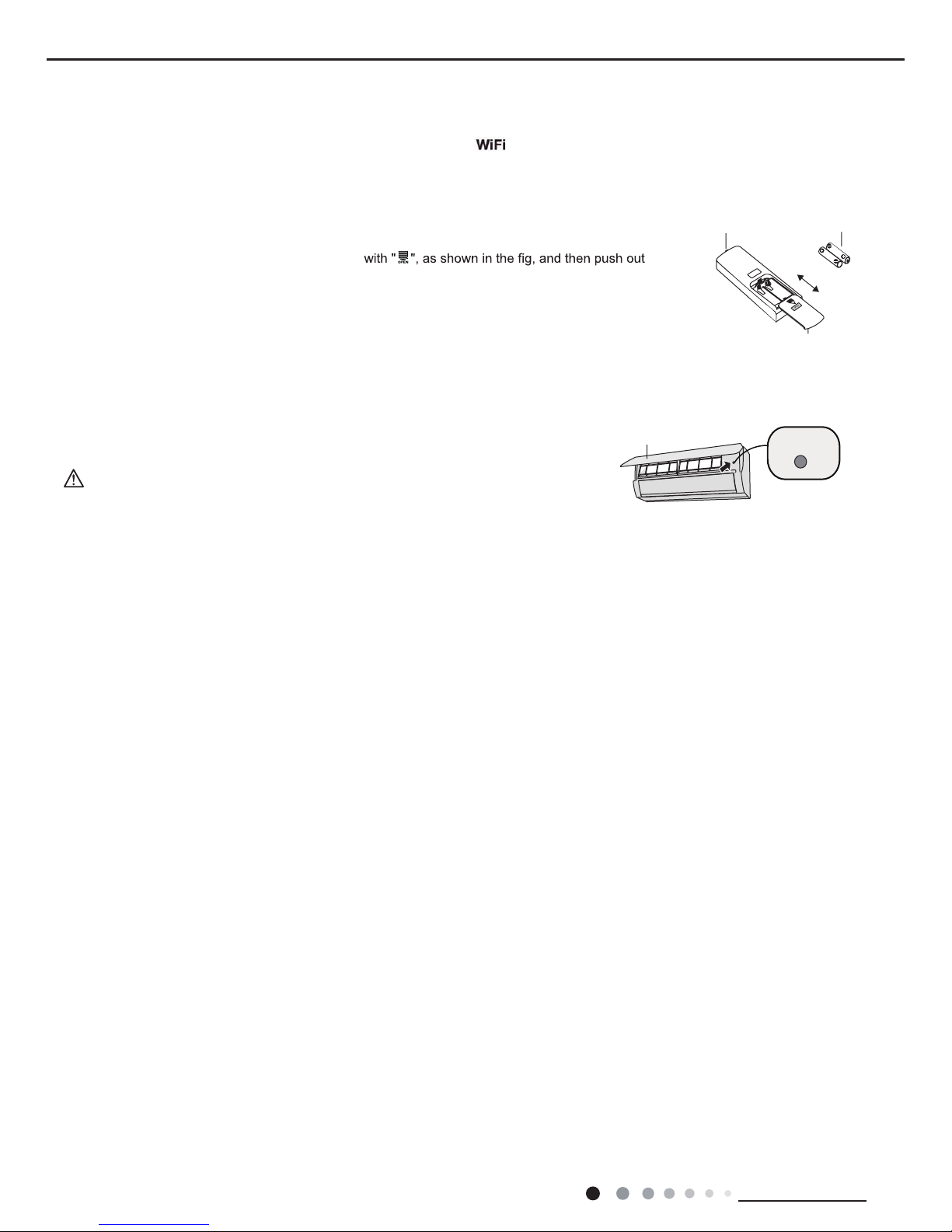
Replacement of batteries in remote controller
Emergency operation
If remote controller is lost or damaged, please use auxiliary button to turn on or turn off the air conditioner.
When the air conditioner is turned on, it will operate under auto mode.
aux. button
panel
WARNING:
Use insulated object to press the auto button
As shown in the fig.Open panel ,press aux.button to turn on or turn off the air conditioner.
The operation in details are as below:
1. Press the back side of remote controller marked
the cover of battery box along the arrow direction.
2. Replace two 7# (AAA 1.5V) dry batteries, and make sure the position of "+" polar and "-" polar
are correct.
3. Reinstall the cover of battery box.
signal senderbattery
Cover of battery box
remove
reinstall
17
Technical Information
Service Manual
6.2 Operation of Smart Control (Smart Phone, Tablet PC) For Gree
NOTE:One AC can be controlled by 4 smart phones in maximum at the same time.
(2).Short-distance and long-distance control setting for air conditioner connecting with router
Step 1: Under short-distance control, return to the homepage "Home Control". Tap at the top right corner of the homepage "Device".
Operation Instructions
Download and install APP
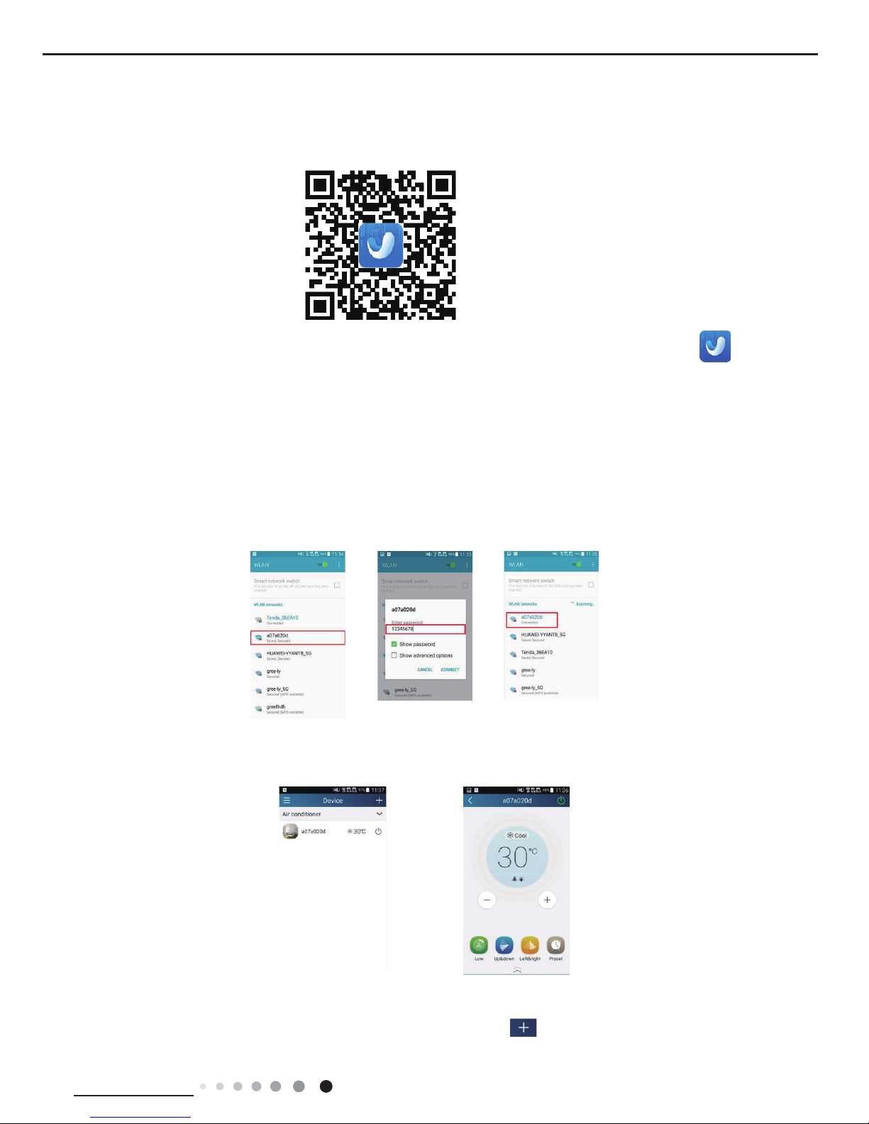
Scan the following QR code with your smart phone and download Wi Smart.
Conguration
Step 2: Open APP and the screen will show the air conditioner that you just connected. Tap the name of this air conditioner on
your phone to enter and realize short-distance control, as shown below. Please refer to "Functions introduction" for specic control
methods.
Install the APP according to its guidance. When successfully installed, your smart phone homepage will show this icon
User of IOS system can search for the Gree Smart in Apple store to download the Apple version APP.
NOTE: Select either the original conguration or AP conguration according to the APP functions.
1.Original conguration
Before operation, please nish the following conguration in order to realize Wi control and the connection between air conditioner and
intelligent device.
(1).Short-distance control setting for air conditioner using Wi hotspot
Step 1: Air conditioner Wi is set in AP mode in factory. You can search the air conditioner Wi hotspot through your smart phone. The
name of Wi hotspot is the last 8 numbers of the air conditioner mac address. Password is 12345678.
18
Technical Information
Service Manual
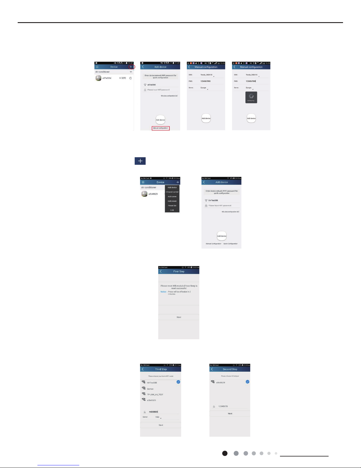
2.AP conguration
4 steps of conguration
Step 1: Enter homepage "Device", and then tap at the top right corner.
Select "Add device" and enter the page "Add device". Tap "Manual Conguration".
Step 2: Tap "Next" in the First Step.
Step 3: Select the wireless network of air conditioner. APP will show the password 12345678 (default password of the network of air
conditioner). Then tap "Next"; select the name of home Wi router, then enter the correct password and select a server.
Select "Add device" and enter the page of "Add device". Tap "Manual conguration" and enter the page "Manual conguration".
Step 2: Select the correct network name and enter the password. Select the server (The server setting here must keep the same as the
server setting in "Settings" mentioned below. Otherwise, remote control will fail.), then tap the button "Add device" for conguration. At
this time, "Conguring" is displayed on the APP. The buzzer in the indoor unit will give out a sound when conguration succeeds.
19
Technical Information
Service Manual
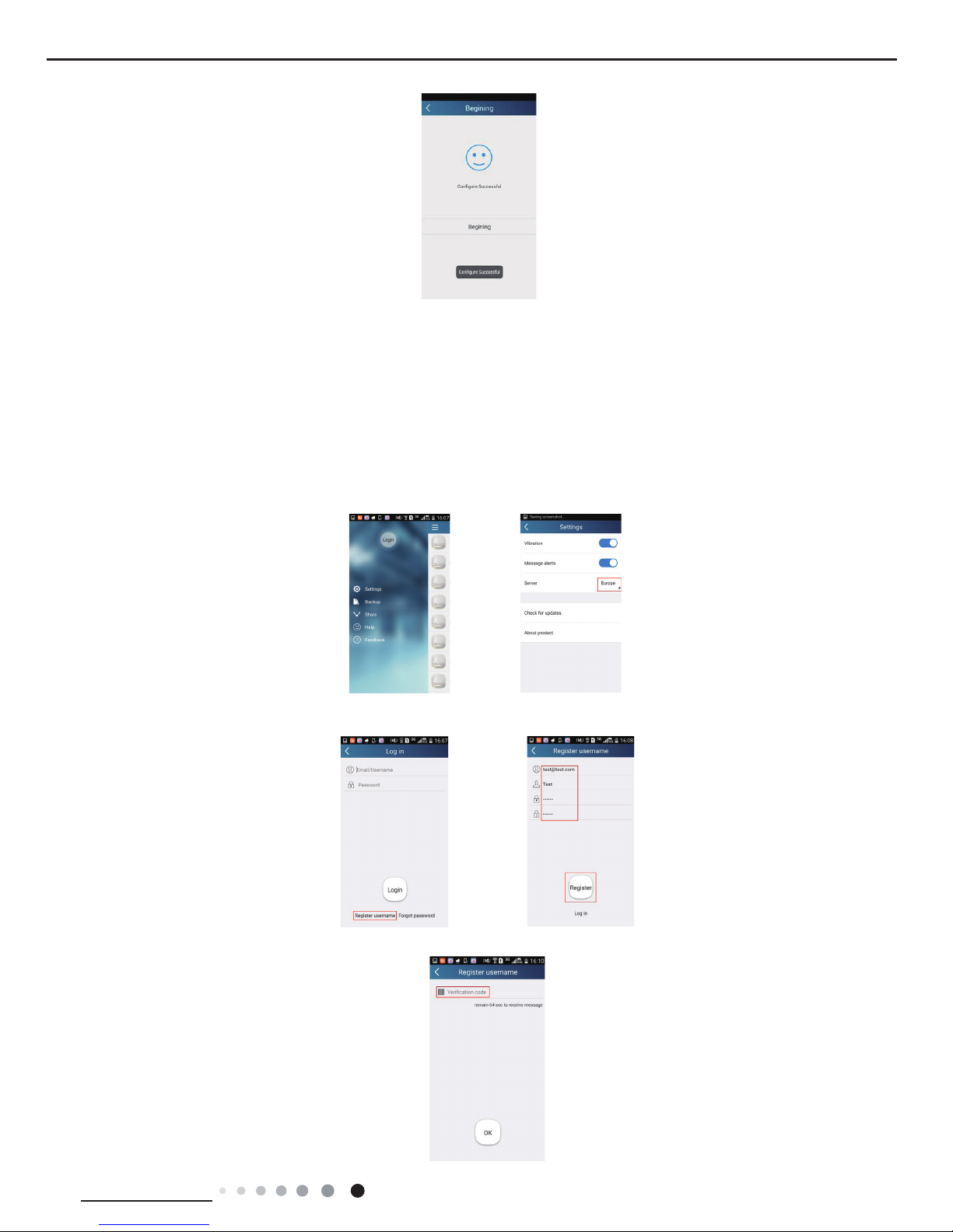
Step 4: If conguration is successful, a window will pop up and read "Conguration succeeded". Then conguration is completed.
NOTE: After conguration is completed, the air conditioner hot spot connected to your phone will disAPPear. You should reconnect your
phone to the home Wi router to realize long-distance control.
The above conguration only needs one phone. Other types of phones shall install this APP, connect with the air conditioner hot spot or
wireless router of Wi air conditioner. When connection is done, open the APP to use short-distance operation to control the air conditioner
and then you can use the long-distance control.
Functions introduction
1.User registration
Purpose: To realize long-distance control
Operation instruction: For the rst time login, you have to register a new username. If you already have a username, skip the registration
step and enter email address and password on the "Login Page" to log in. If password is forgotton, you can reset the password.
Operation steps:
(1) Select the sever address
(2) Account login: Slide the page "Device", and enter the page "Menu" on the left. Tap "Login" to enter the page "Register username". New
user must rst register a username. Tap "Register”.
(3) Enter your email address. Wait until you receive the verication code. Enter the code and then tap "OK" to log in.
20
Technical Information
Service Manual
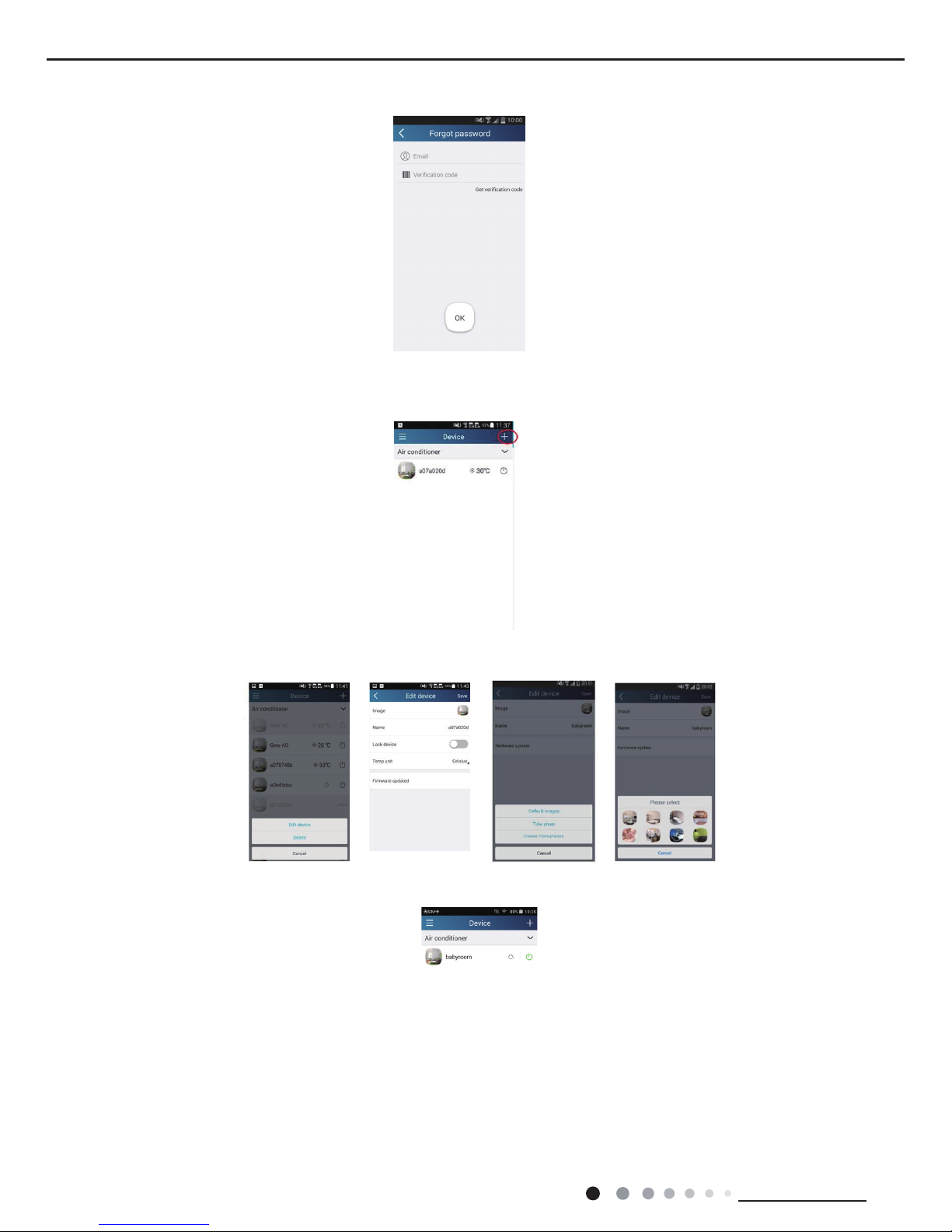
(4) If password is forgotten, you can reset the password with your email address.
Tap "Forgot password" and enter the page "Forgot password". Tap "Get verication code" to get an email verication code. Enter a new
password and tap "OK" to log in.
2.Personal settings
Purpose: Set name (device name, preset name, etc.) and images (device image) in order to identify a user easily.
(1) Set device name
After quick conguration, a list of controllable smart devices will be generated. Default name for air conditioner is the last 8 numbers of the
air condtioner mac address.
Step 1: Tap and hold "a0b417ac" to enter the page "Edit device". Tap "Image" to select the source of image. Select from "Default images"
or "Take photo" or "Choose from photos" and save an image.
Step 2: Tap "Name" to change device name. Save it and the new device name will be shown. Enable button Lock device to lock the device
so that other smart phones cant search the device. Tap "Temp unit" to change the temperature unit.
Step 3: Tap "Firmware update" to upgrade the rmware of the device. Tap"1.8" the device will upgraded auto.

21
Technical Information
Service Manual
(2) Set preset name
Step 1: Tap at the top right corner of the homepage "Device". Select "Add preset" and enter the page "Preset edit".
Step 2: Choose the time. Tap "Name". As shown in the picture, its name is "baby room". For timer type, select "On". Then select the
repeating days. Save the setting of preset name.
(3) Set device image
Please refer to step 1 in 2(1)
3.Control functions
(1) Common control functions: General control on the operation of smart devices (On/Off, temperature, fan speed, mode, etc.) and the
setting of advanced functions (air exchange, dry, health, light, sleep, energy saving upper limit).
Step 1: General control
Enter the homepage "Home control" rst. Take "babyroom"as an example.
Tap "babyroom" and enter the page of air conditioner control. Tap to turn on the control switch.

22
Technical Information
Service Manual
Tap or to increase or decrease temperature. Tap to change working mode. Tap to enter the page of fan speed
adjustment.
Tap and go around the circle to adjust fan speed.
Step 2: Advanced settings
Tap to enter advanced settings. You may select "Air", "Dry", "Health", "Light", "Sleep" or "Energy saving".
(2) Advanced control functions: Set scene; Preset; Link; Infrared control (only APPlicable to smart phones with infrared emitter)
Set scene: Preset the operation of several smart devices by one tap.
On the page "Home control", tap the image of "Home control" to enter the page "Edit scene".
23
Technical Information
Service Manual
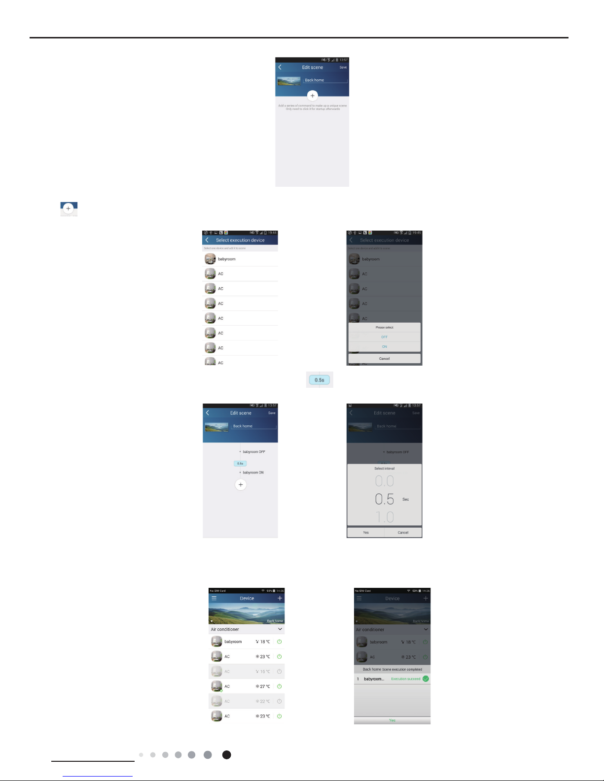
Tap "Add scene" and edit the scene name, for example, "Back home". Add execution devices.
Tap to add commands. On the page "Select execution device", select the air conditioner named "babyroom". Then select "ON" or
"OFF".
Continue to select the next execution device as instructed above. Tap to set the interval.
Tap "Save". Tap the scene picture displayed on homepage "Device" to send the command. Then the scene "Back home" will be in execution.
You may view the execution condition of the scene.
24
Technical Information
Service Manual
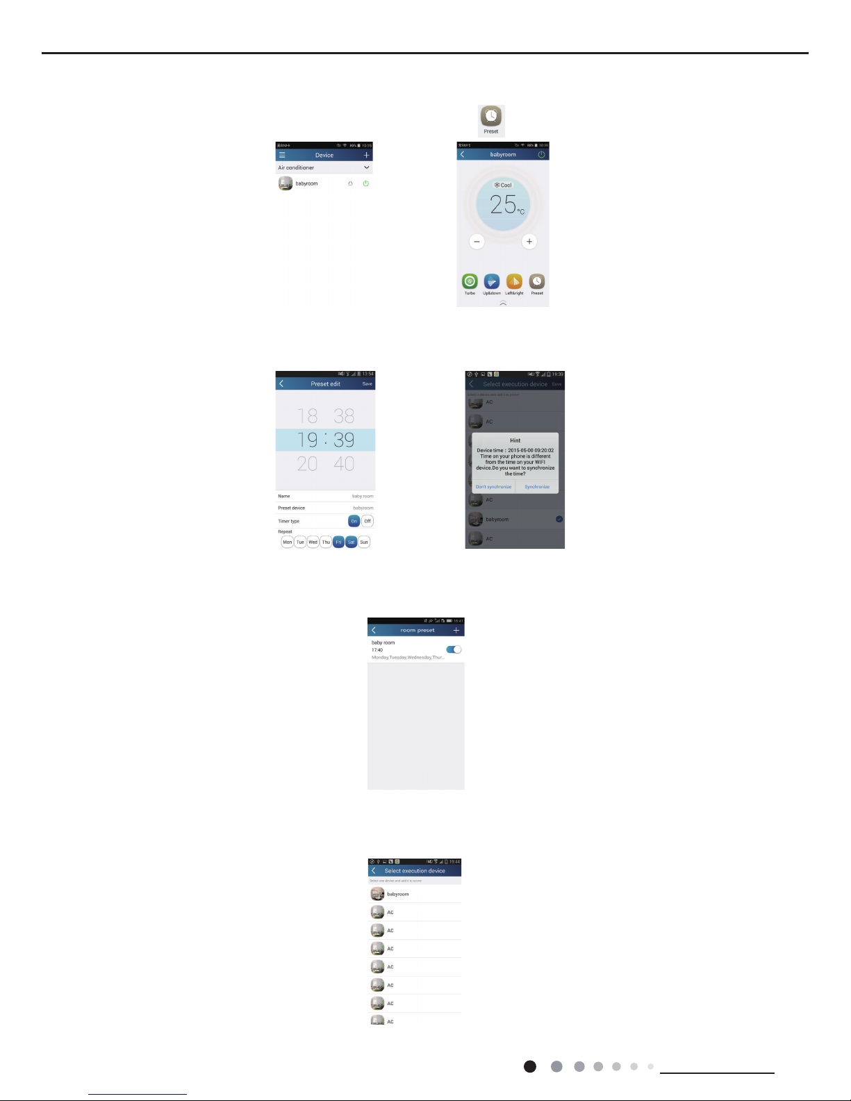
(3) Preset includes single-device preset and multi-device preset
Single-device preset: This can preset a certain device to be On/Off at a specic time.
On the homepage "Device", take air conditioner "babyroom" as an example. Tap at the bottom of the page "babyroom". Then you will
enter the page "Preset edit".
Slide up and down to set the time. If you need to synchronize the time, tap " synchronize". If such "Hint" interface doesnt show up, please
skip this operation procedure.
Tap "Name" to customize the preset name.
Preset device cant be selected and it will default to "babyroom". Select "On" for the timer type. Select repeating days to complete the
preset.
Multi-device preset: This can preset multiple devices to execute a command at a specic time.
Please refer to the instructions as how to set preset time, name, timer type and repeating days for a single device.
Tap "Preset device" to select one or more devices. Then return to the page "Device".
25
Technical Information
Service Manual
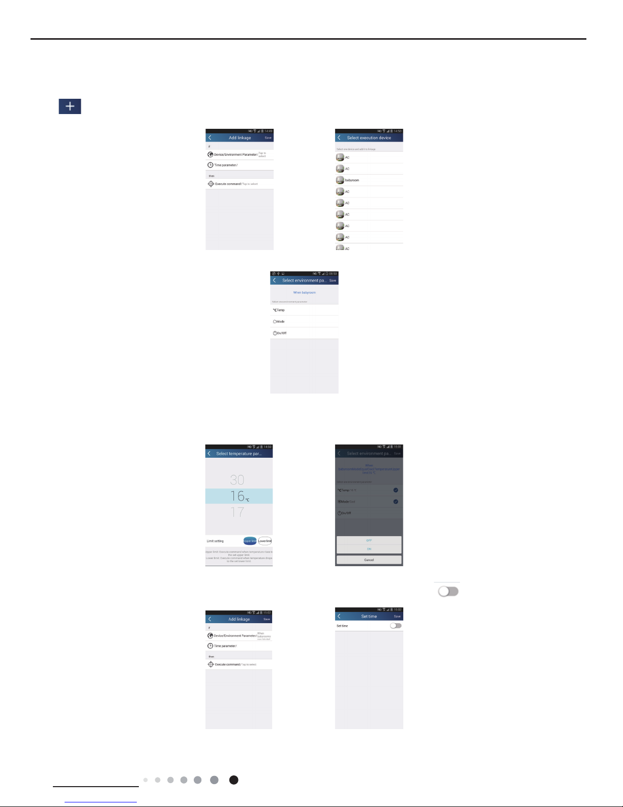
(4) Link(This function is APPlicable to some models)
Select a master device. When the environment satisfies the parameters as set in the master device, slave devices will execute
commands to realize devices linkage.
Step 1: Set the parameters of master device (Select master device, select environment parameters, select master device status).
Tap at the top right corner of the homepage "Device". Select "Link" and enter the page "Add linkage". Tap "Device/Param" to
enter the page "Select device". Take "baby room" as an example. Tap "babyroom".
Enter the page "Select environment parameters".
Tap "Temperature" to enter the page "Select temperature parameter". Slide up or down to adjust temperature. Tap "Upper limit" or
"Lower limit".
Tap "Mode" and "On/Off" to select the status of master device. Then tap "Save".
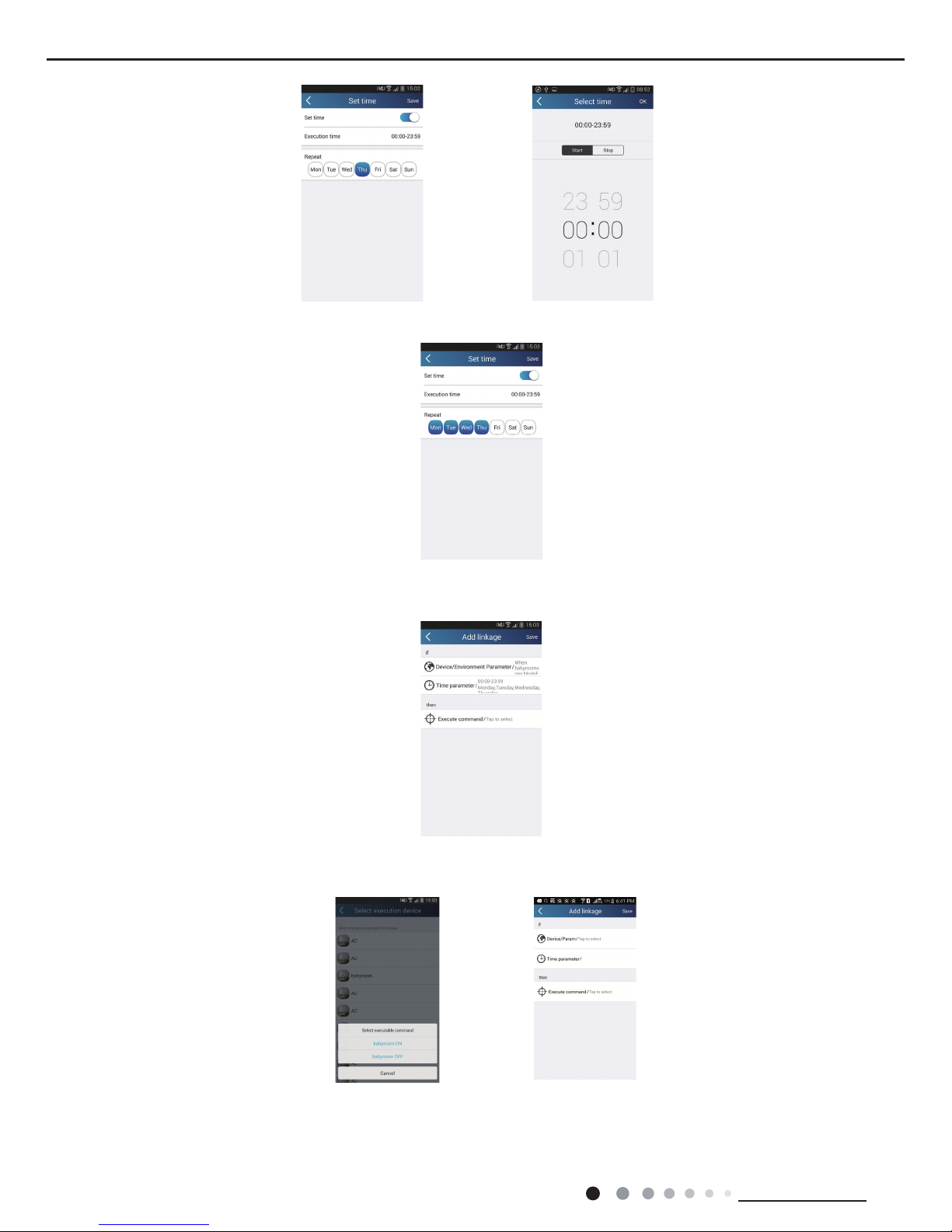
Step 2: Set time parameter for linkage. Tap "Time parameter" to enter the page "Set time". Slide rightwards to turn on the
setting time.
Tap "Execution time"; then tap "Start" and "Stop" to set start time and stop time respectively. Tap "OK" at the top right corner to save the
setting.
26
Technical Information
Service Manual
Tap the days below "Repeat" to select the repeating days. Then tap "Save".
Step 3: Select "Execute command"
Tap "Execute command" and enter the page "Select device".
Tap the name of device that you want to control. Tap "ON" or "OFF" and then tap "Save" to complete the linkage.
Tap "Save" and then repeat the above steps to set linkage of several scenes.
27
Technical Information
Service Manual
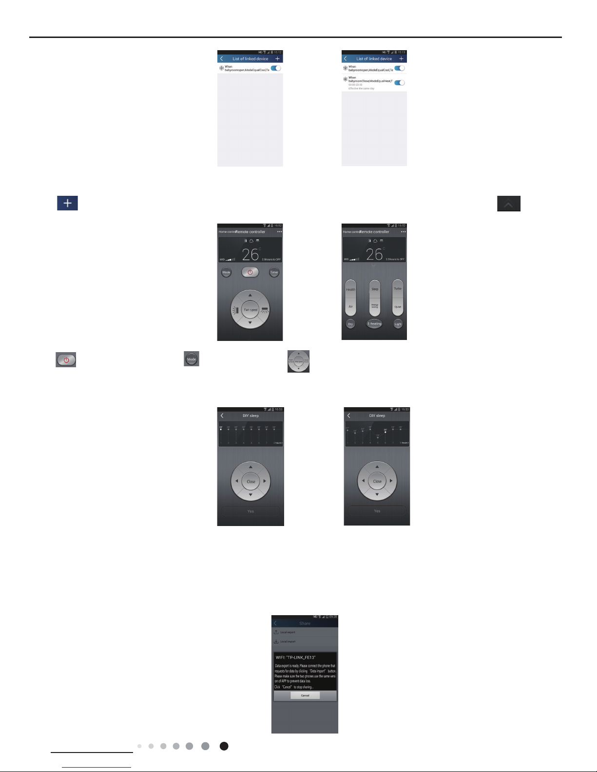
(5) Infrared control (only APPlicable to smart phones with infrared emitter).
Function: Smart phone can be used as a remote controller.
Tap at the top right corner of the homepage "Device". Select "Infrared" and enter the page "Remote controller". Tap and
slide up to enter the page of advanced functions.
Tap to turn on the device. Tap to select mode. Tap to adjust fan speed and swing angle. Tap "Health", "Energy
saving", "Sleep" etc. to set advanced functions.
Tap "Sleep" to enter the page "Sleep". You can select "Traditional sleep", "Expert sleep" or "DIY sleep". Tap "DIY sleep" and then tap
the left and right arrows to set sleep time. Tap up and down arrows to adjust temperature at a specic sleep time.
4.Menu functions
Menu functions (Share, Set, History, Feedback)
(1) Share: To share quick conguration information and units information, including local export and local import.
For local import, you just need to tap "Local import" and wait for the data download.
Local export
Step 1: Export local data to another smart phone.
Enter "Menu" on the left side and tap "Share" to enter the page "Share". Then tap "Local export".
 Loading...