

Gree GWH09YC-K6DNA1A, GWH12YC-K6DNA2A, GWH09YC-K6DNA2A, GWH12YC-K6DNA1A Service Manual

GREE ELECTRIC APPLIANCES,INC.OF ZHUHAI
Change for Life
Service Manual
Models:
GWH09YC-K6DNA1A
GWH09YC-K6DNA2A
GWH12YC-K6DNA1A
GWH12YC-K6DNA2A
(Refrigerant R32)

Service Manual
Table of Contents
Part
Ⅰ
: Technical Information
.......................................................................1
1. Summary
......................................................................................................................1
2. Specications
..........................................................................................................2
2.1 Specication Sheet ...........................................................................................................2
2.2 Operation Characteristic Curve ........................................................................................6
2.3 Capacity Variation Ratio According to Temperature .........................................................6
2.4 Cooling and Heating Data Sheet in Rated Frequency .....................................................8
2.5 Noise Curve ......................................................................................................................8
3. Outline Dimension Diagram
........................................................................9
3.1 Indoor Unit ........................................................................................................................9
3.2 Outdoor Unit ...................................................................................................................10
4. Refrigerant System Diagram
.................................................................... 11
5. Electrical Part
.........................................................................................................12
5.1 Wiring Diagram ...............................................................................................................12
5.2 PCB Printed Diagram .....................................................................................................16
6. Function and Control
......................................................................................18
6.1 Remote Controller Introduction .....................................................................................18
6.2 GREE+ App Operation Manual ......................................................................................23
6.3 Ewpe Smart App Operation Manual ...............................................................................24
6.4 Brief Description of Modes and Functions ......................................................................25
Part
Ⅱ
: Installation and Maintenance
.................................................30
7. Notes for Installation and Maintenance
..........................................30
8. Installation
................................................................................................................33
8.1 Installation Dimension Diagram ......................................................................................33
8.2 Installation Parts-checking ............................................................................................35
8.3 Selection of Installation Location ....................................................................................35
8.4 Requirements for electric connection .............................................................................35
8.5 Installation of Indoor Unit ................................................................................................35
8.6 Installation of Outdoor unit .............................................................................................38
8.7 Vacuum Pumping and Leak Detection ...........................................................................39
8.8 Check after Installation and Test operation ....................................................................39
Table of Contents

Service Manual
9. Maintenance
............................................................................................................40
9.1 Troubleshooting for Normal Malfunction .........................................................................40
9.2 Error Code List ...............................................................................................................44
9.3 Troubleshooting for Main Malfunction ............................................................................51
10. Exploded View and Parts List
..............................................................63
10.1 Indoor Unit ....................................................................................................................63
10.2 Outdoor Unit .................................................................................................................67
11. Removal Procedure
.......................................................................................70
11.1 Removal Procedure of Indoor Unit ...............................................................................70
11.2 Removal Procedure of Outdoor Unit ............................................................................75
Appendix:
........................................................................................................................79
Appendix 1: Reference Sheet of Celsius and Fahrenheit ....................................................79
Appendix 2: Conguration of Connection Pipe .....................................................................79
Appendix 3: Pipe Expanding Method ...................................................................................80
Appendix 4: List of resistance for Temperature Sensor ........................................................81
Table of Contents
1
Technical Information
Service Manual
1. Summary
Part
Ⅰ
: Technical Information
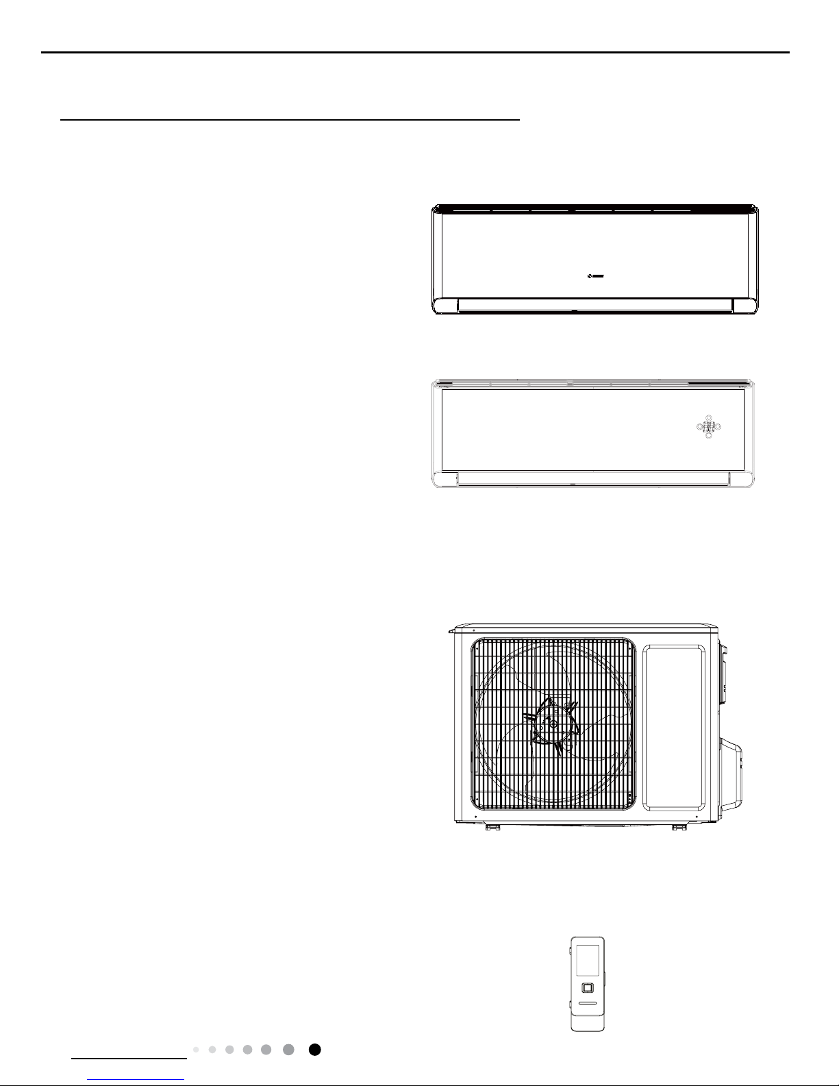
Indoor Unit
GWH09YC-K6DNA1A/I
GWH12YC-K6DNA1A/I
GWH09YC-K6DNA2A/I
GWH12YC-K6DNA2A/I
Outdoor Unit
GWH09YC-K6DNA1A/O
GWH12YC-K6DNA1A/O
Remote Controller
YAG1FB
FAN
MODE
ON/OF
F
+-

2
Technical Information
Service Manual
2. Specications
2.1 Specication Sheet
Parameter Unit Value
Model
GWH09YC-K6DNA1A
GWH09YC-K6DNA2A
GWH12YC-K6DNA1A
GWH12YC-K6DNA2A
Product Code
CB437001600
CB466001600
CB437001100
CB466001500
Power
Supply
Rated Voltage V~ 220-240 220-240
Rated Frequency Hz 50 50
Phases 1 1
Power Supply Mode Outdoor Outdoor
Cooling Capacity W 2700 3500
Heating Capacity W 2930 3810
Cooling Power Input W 585 950
Heating Power Input W 650 975
Cooling Current Input A 2.6 4.0
Heating Current Input A 2.9 4.5
Rated Input W 1650 1650
Rated Current A 6.4 6.4
Air Flow Volume(SH/H/MH/M/ML/L/SL) m3/h 660/590/540/490/450/420/390 680/590/540/490/450/420/390
Dehumidifying Volume L/h 0.8 1.4
EER W/W 4.62 3.68
COP W/W 4.51 3.91
SEER W/W 8.5 8.5
SCOP(Average/Warmer/Colder) W/W 4.6/5.4/3.8 4.4/5.1/3.5
Application Area m
2
12-18 16-24
Indoor
Unit
Indoor Unit Model
GWH09YC-K6DNA1A/I
GWH09YC-K6DNA2A/I
GWH12YC-K6DNA1A/I
GWH12YC-K6DNA2A/I
Indoor Unit Product Code
CB437N01600
CB466N01600
CB437N01100
CB466N01500
Fan Type Cross-ow Cross-ow
Fan Diameter Length(DXL) mm Ф98X633.5 Ф98X633.5
Cooling Speed r/min 1300/1200/1120/1050/980/920/750 1350/1200/1120/1050/980/920/750
Heating Speed r/min 1300/1200/1140/1080/1020/960/900 1350/1200/1140/1080/1020/960/900
Fan Motor Power Output W 20 20
Fan Motor RLA A 0.09 0.09
Fan Motor Capacitor μF / /
Evaporator Form Aluminum Fin-copper Tube Aluminum Fin-copper Tube
Evaporator Pipe Diameter mm Ф5 Φ5
Evaporator Row-n Gap mm 2-1.4 2-1.4
Evaporator Coil Length (LXDXW) mm 635X22.8X306.3 635X22.8X306.3
Swing Motor Model MP24EB/MP24HF MP24EB/MP24HF
Swing Motor Power Output W 1.5/1.5 1.5/1.5
Fuse Current A 3.15 3.15
Sound Pressure Level(SH/H/MH/M/ML/L/SL) dB (A) 41/39/37/35/33/31/24 43/39/37/35/34/32/25
Sound Power Level(SH/H/MH/M/ML/L/SL) dB (A) 56/53/52/50/48/46/39 58/53/52/50/48/46/46
Dimension (WXHXD) mm 865X290X210 865X290X210
Dimension of Carton Box (LXWXH) mm 928X278X364 928X278X364
Dimension of Package(LXWXH) mm 931X281X379 931X281X379
Net Weight kg 10.5 11
Gross Weight kg 12.5 13
3
Technical Information
Service Manual
The above data is subject to change without notice. Please refer to the nameplate of the unit.
Outdoor
Unit
Outdoor Unit Model GWH09YC-K6DNA1A/O GWH12YC-K6DNA1A/O
Outdoor Unit Product Code CB437W01600 CB437W01100
Compressor Manufacturer
ZHUHAI LANDA COMPRESSOR
CO.,LTD
ZHUHAI LANDA COMPRESSOR
CO., LTD
Compressor Model QXF-B096zE190A QXF-B096zE190A
Compressor Oil FW68DA FW68DA
Compressor Type Rotary Rotary
Compressor LRA. A 20.00 20
Compressor RLA A 4.21 4.21
Compressor Power Input W 943 943
Compressor Overload Protector
1NT11L-6233 HPC115/95U1
KSD115ºC
1NT11L-6233 HPC115/95U1
KSD115ºC
Throttling Method Electron expansion valve Electron expansion valve
Set Temperature Range ºC 16~30 16~30
Cooling Operation Ambient Temperature
Range
ºC -15~43 -15~43
Heating Operation Ambient Temperature
Range
ºC -15~24 -15~24
Condenser Form Aluminum Fin-copper Tube Aluminum Fin-copper Tube
Condenser Pipe Diameter mm Φ7 Φ7
Condenser Rows-n Gap mm 2-1.4 2-1.4
Condenser Coil Length (LXDXW) mm 742X38.1X550 742X38.1X550
Fan Motor Speed rpm 900/650 900/650
Fan Motor Power Output W 30 30
Fan Motor RLA A 0.36 0.36
Fan Motor Capacitor μF / /
Outdoor Unit Air Flow Volume m3/h 2200 2200
Fan Type Axial-ow Axial-ow
Fan Diameter mm Φ438 Φ438
Defrosting Method Automatic Defrosting Automatic Defrosting
Climate Type T1 T1
Isolation I I
Moisture Protection IPX4 IPX4
Permissible Excessive Operating Pressure
for the Discharge Side
MPa 4.3 4.3
Permissible Excessive Operating Pressure
for the Suction Side
MPa 2.5 2.5
Sound Pressure Level (H/M/L) dB (A) 52/-/- 53/-/-
Sound Power Level (H/M/L) dB (A) 60/-/- 62/-/-
Dimension(WXHXD) mm 848X596X320 848X596X320
Dimension of Carton Box (LXWXH) mm 878X360X630 878X360X630
Dimension of Package(LXWXH) mm 881X363X645 881X363X645
Net Weight kg 33.5 33.5
Gross Weight kg 36.5 36.5
Refrigerant R32 R32
Refrigerant Charge kg 0.7 0.75
Connection
Pipe
Connection Pipe Length m 5 5
Connection Pipe Gas Additional Charge g/m 16 16
Outer Diameter Liquid Pipe mm Φ6 Φ6
Outer Diameter Gas Pipe mm Φ9.52 Φ9.52
Max Distance Height m 10 10
Max Distance Length m 15 20
Note: The connection pipe applies metric diameter.
4
Technical Information
Service Manual
Parameter Unit Value
Model
GWH12YC-K6DNA1A
GWH12YC-K6DNA2A
GWH09YC-K6DNA1A
GWH09YC-K6DNA2A
Product Code
CB437001101
CB466001501
CB437001601
CB466001601
Power
Supply
Rated Voltage V~ 220-240 220-240
Rated Frequency Hz 50 50
Phases 1 1
Power Supply Mode Outdoor Outdoor
Cooling Capacity W 3500 2700
Heating Capacity W 3810 2930
Cooling Power Input W 950 585
Heating Power Input W 975 650
Cooling Current Input A 4.0 2.6
Heating Current Input A 4.5 2.9
Rated Input W 1650 1650
Rated Current A 6.4 6.4
Air Flow Volume(SH/H/MH/M/ML/L/SL) m3/h 680/590/540/490/450/420/390 660/590/540/490/450/420/390
Dehumidifying Volume L/h 1.4 0.8
EER W/W 3.68 4.62
COP W/W 3.91 4.50
SEER W/W 8.5 8.5
SCOP(Average/Warmer/Colder) W/W 4.4/5.1/3.5 4.6/5.4/3.8
Application Area m
2
16-24 12-18
Indoor
Unit
Indoor Unit Model
GWH12YC-K6DNA1A/I
GWH12YC-K6DNA2A/I
GWH09YC-K6DNA1A/I
GWH09YC-K6DNA2A/I
Indoor Unit Product Code
CB437N01101
CB466N01501
CB437N01601
CB466N01601
Fan Type Cross-ow Cross-ow
Fan Diameter Length(DXL) mm Ф98X633.5 Ф98X633.5
Cooling Speed r/min 1350/1200/1120/1050/980/920/750
1300/1200/1120/1050/980/920/750/5
00
Heating Speed r/min 1350/1200/1140/1080/1020/960/900 1300/1200/1140/1080/1020/960/900/-
Fan Motor Power Output W 20 20
Fan Motor RLA A 0.09 0.09
Fan Motor Capacitor μF / /
Evaporator Form Aluminum Fin-copper Tube Aluminum Fin-copper Tube
Evaporator Pipe Diameter mm Φ5 Ф5
Evaporator Row-n Gap mm 2-1.4 2-1.4
Evaporator Coil Length (LXDXW) mm 635X22.8X306.3 635×22.8×306.3
Swing Motor Model MP24EB/MP24HF MP24EB/MP24HF
Swing Motor Power Output W 1.5/1.5 1.5/2
Fuse Current A 3.15 3.15
Sound Pressure Level(SH/H/MH/M/ML/L/
SL)
dB (A) 43/39/37/35/34/32/25 41/39/35/31
Sound Power Level(SH/H/MH/M/ML/L/
SL)
dB (A) 58/53/52/50/48/46/46 56/53/50/46
Dimension (WXHXD) mm 865X290X210 865X290X210
Dimension of Carton Box (LXWXH) mm 928X278X364 928X278X364
Dimension of Package(LXWXH) mm 931X281X379 931X281X379
Net Weight kg 11 10.5
Gross Weight kg 13 12.5
5
Technical Information
Service Manual
The above data is subject to change without notice. Please refer to the nameplate of the unit.
Outdoor
Unit
Outdoor Unit Model GWH12YC-K6DNA1A/O GWH09YC-K6DNA1A/O(LCLH)
Outdoor Unit Product Code CB437W01101 CB437W01601
Compressor Manufacturer
ZHUHAI LANDA COMPRESSOR
CO., LTD
ZHUHAI LANDA COMPRESSOR
CO.,LTD
Compressor Model QXF-B096zE190A QXF-B096zE190A
Compressor Oil FW68DA FW68DA
Compressor Type Rotary Rotary
Compressor LRA. A 20 20.00
Compressor RLA A 4.21 4.21
Compressor Power Input W 943 943
Compressor Overload Protector
1NT11L-6233 HPC115/95U1
KSD115ºC
1NT11L-6233 HPC115/95U1
KSD115ºC
Throttling Method Electron expansion valve Electron expansion valve
Set Temperature Range ºC 16~30 16~30
Cooling Operation Ambient Temperature
Range
ºC -15~43 -15~43
Heating Operation Ambient Temperature
Range
ºC -22~24 -22~24
Condenser Form Aluminum Fin-copper Tube Aluminum Fin-copper Tube
Condenser Pipe Diameter mm Φ7 Φ7
Condenser Rows-n Gap mm 2-1.4 2-1.4
Condenser Coil Length (LXDXW) mm 742X38.1X550 742X38.1X550
Fan Motor Speed rpm 900/650 900/650
Fan Motor Power Output W 30 30
Fan Motor RLA A 0.36 0.36
Fan Motor Capacitor μF / /
Outdoor Unit Air Flow Volume m3/h 2200 2200
Fan Type Axial-ow Axial-ow
Fan Diameter mm Φ438 Φ438
Defrosting Method Automatic Defrosting Automatic Defrosting
Climate Type T1 T1
Isolation I I
Moisture Protection IPX4 IPX4
Permissible Excessive Operating Pressure
for the Discharge Side
MPa 4.3 4.3
Permissible Excessive Operating Pressure
for the Suction Side
MPa 2.5 2.5
Sound Pressure Level (H/M/L) dB (A) 53/-/- 52/-/-
Sound Power Level (H/M/L) dB (A) 62/-/- 60/-/-
Dimension(WXHXD) mm 848X596X320 848X596X320
Dimension of Carton Box (LXWXH) mm 878X360X630 878X360X630
Dimension of Package(LXWXH) mm 881X363X645 881X363X645
Net Weight kg 33.5 33.5
Gross Weight kg 36.5 36.5
Refrigerant R32 R32
Refrigerant Charge kg 0.75 0.7
Connection
Pipe
Connection Pipe Length m 5 5
Connection Pipe Gas Additional Charge g/m 16 16
Outer Diameter Liquid Pipe mm Φ6 Φ6
Outer Diameter Gas Pipe mm Φ9.52 Φ9.52
Max Distance Height m 10 10
Max Distance Length m 20 15
Note: The connection pipe applies metric diameter.
6
Technical Information
Service Manual
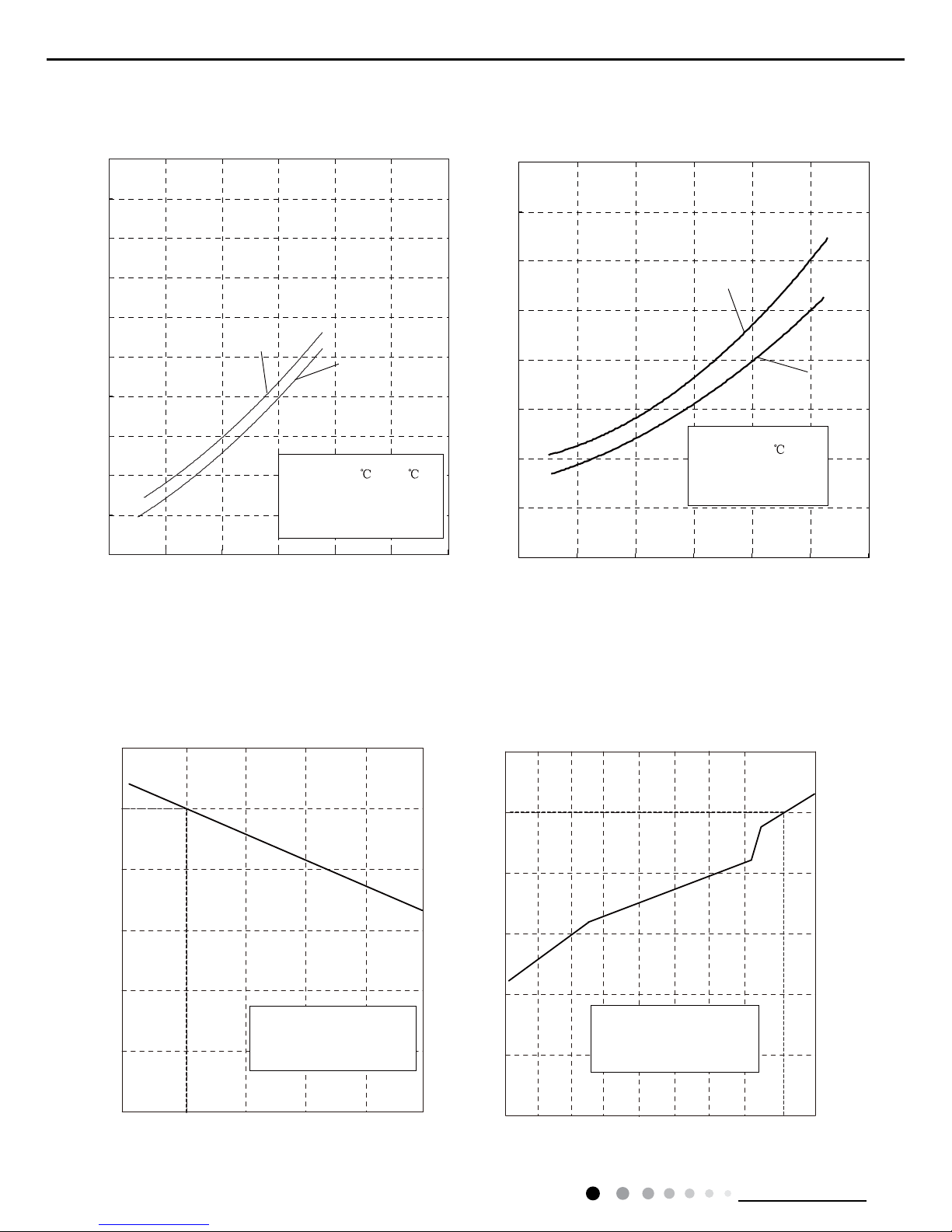
2.2 Operation Characteristic Curve
2.3 Capacity Variation Ratio According to Temperature
0
1
2
3
4
5
6
7
8
9
10
020406080 100 120
Condition
Indoor:DB 27
WB19
Indoor air flow: Turbo
Pipe length:5m
Voltage:230V
Compressor Speed(rps)
0
1
2
3
4
5
6
7
8
020406080 100
120
Condition
Indoor:DB 20
Indoor air flow:Turbo
Pipe length:5m
Voltage:230V
Compressor Speed(rps)
Current(A)
Current(A)
09K
12K
09K
12K
Cooling:
Cooling:
GWH09YC-K6DNA1A/O GWH12YC-K6DNA1A/O
Heating:
Heating:
50
60
70
80
90
100
110
Capacity ratio(%)
Condition
Indoor air flow: Super High
Pipe length:
5m
Outdoor temp. (°C)
0
20
40
60
80
100
120
Capacity ratio(%)
Condition
Indoor air flow: Super High
Pipe length:
5m
Outdoor temp. (°C)
Indoor:DB 20°C
Indoor:DB 27°C
WB19
°C
33 36 39 42 45 48
-15-12 -9 -6 -3 -1 10725

7
Technical Information
Service Manual
GWH12YC-K6DNA1A/O GWH09YC-K6DNA1A/O GWH09YC-K6DNA1A/O
-12-9-6-3-1
50
60
70
80
90
100
110
Capacity ratio(%)
Condition
Indoor air flow: Super High
Pipe length:
5m
Outdoor temp. (°C)
0
20
-22
40
60
80
100
120
Capacity ratio(%)
Condition
Indoor air flow: Super High
Pipe length:
5m
Outdoor temp. (°C)
Indoor:DB 20°C
Indoor:DB 27°C
WB19
°C
33 36 39 42 45 48
10725
Cooling:
Heating:
8
Technical Information
Service Manual
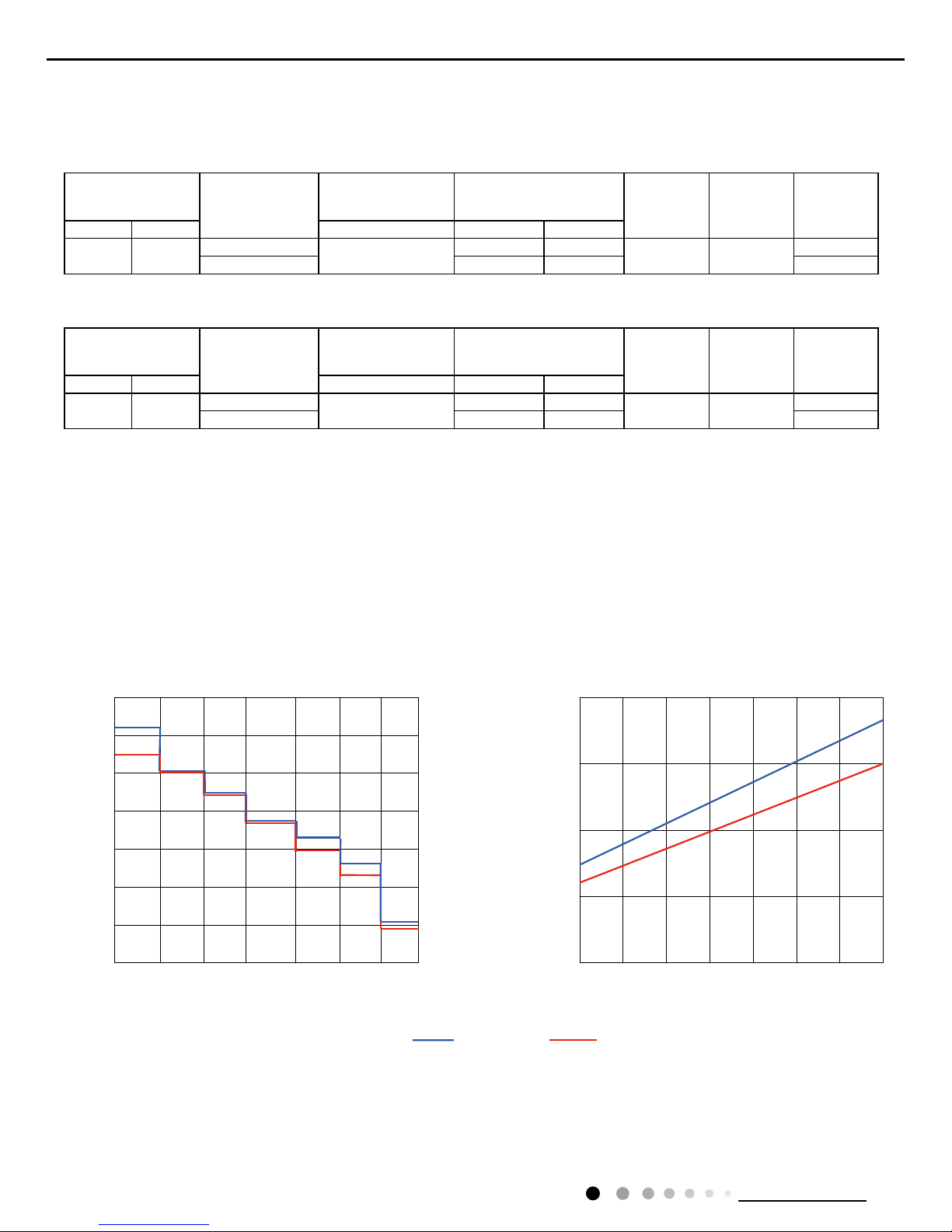
2.4 Cooling and Heating Data Sheet in Rated Frequency
2.5 Noise Curve
Cooling:
Rated cooling
condition(°C) (DB/WB)
Model
Pressure of gas pipe
connecting indoor and
outdoor unit
Inlet and outlet pipe
temperature of heat
exchanger
Fan speed of
indoor unit
Fan speed of
outdoor unit
Compressor
revolution
(rps)
Indoor Outdoor P (MPa) T1 (°C) T2 (°C)
27/19 35/24
09K
0.8 ~ 1.1
12 to 15 65 to 38
TURBO High
49
12K 11 to 14 64 to 37 60
Instruction:
T1: Inlet and outlet pipe temperature of evaporator
T2: Inlet and outlet pipe temperature of condenser
P: Pressure at the side of big valve
Connection pipe length: 5m.
Heating:
Rated cooling
condition(°C) (DB/WB)
Model
Pressure of gas pipe
connecting indoor and
outdoor unit
Inlet and outlet pipe
temperature of heat
exchanger
Fan speed of
indoor unit
Fan speed of
outdoor unit
Compressor
revolution
(rps)
Indoor Outdoor P (MPa) T1 (°C) T2 (°C)
20/- 7/6
09K
2.8 ~ 3.2
35 to 63 2 to 5
TURBO High
59
12K 35 to 65 2 to 5 67
25
30
33
20
36
39
42
45
75 60 45 30 15
Compressor frequency(Hz)
Noise dB(A)
Indoor fan motor rating speed
Noise/dB(A)
40
50
55
60
65
12K 09K
SHHMHMMLLSL
9
Technical Information
Service Manual
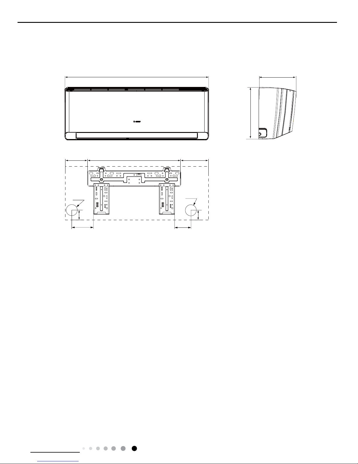
3. Outline Dimension Diagram
3.1 Indoor Unit
Unit:mm
865
210
290
133.5 541.6 189.9
83.2
124.7
35
Φ55
Φ55
35
10
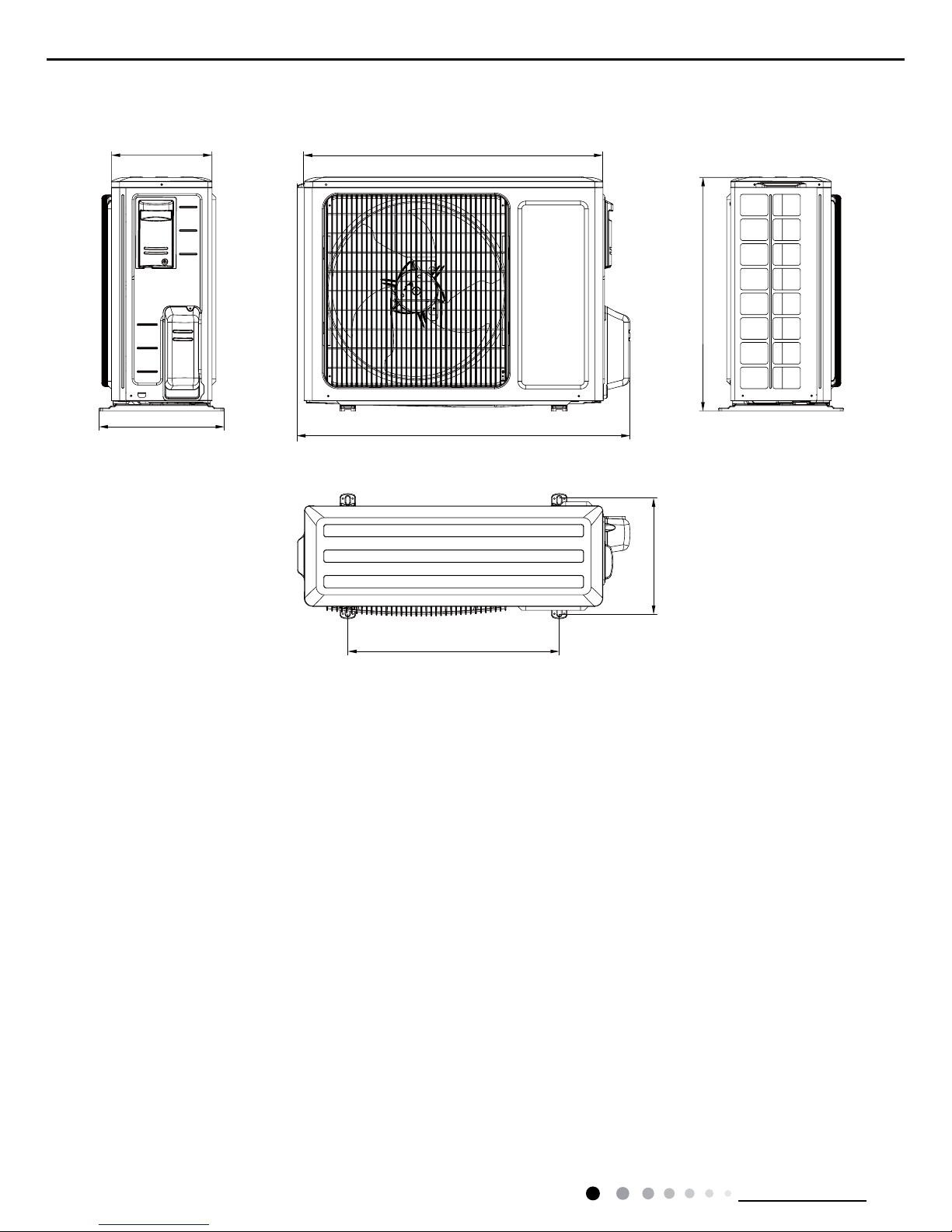
Technical Information
Service Manual
3.2 Outdoor Unit
257
780
596
848
286
540
320
Unit:mm
11
Technical Information
Service Manual
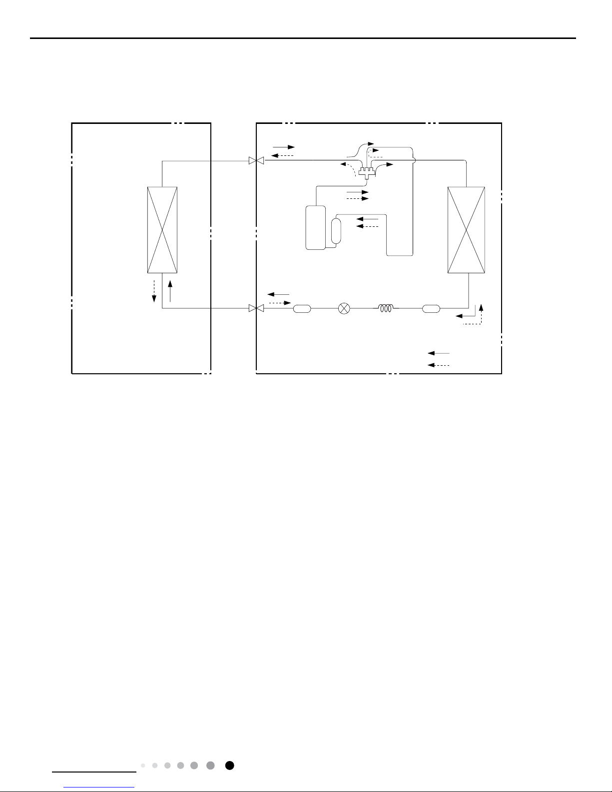
Indoor unit
Outdoor unit
COOLING
HEATING
4-Way valve
Discharge
Suction
Heat
exchanger
(evaporator)
Heat
exchanger
(condenser)
Valve
Valve
Liquid pipe
side
Gas pipe
side
Strainer
Electron
expansion
valve
Strainer
Capillary
Accumlator
Compressor
4. Refrigerant System Diagram
Connection pipe specication:
Liquid pipe:1/4" (6mm)
Gas pipe:3/8" (9.52mm)
12
Technical Information
Service Manual
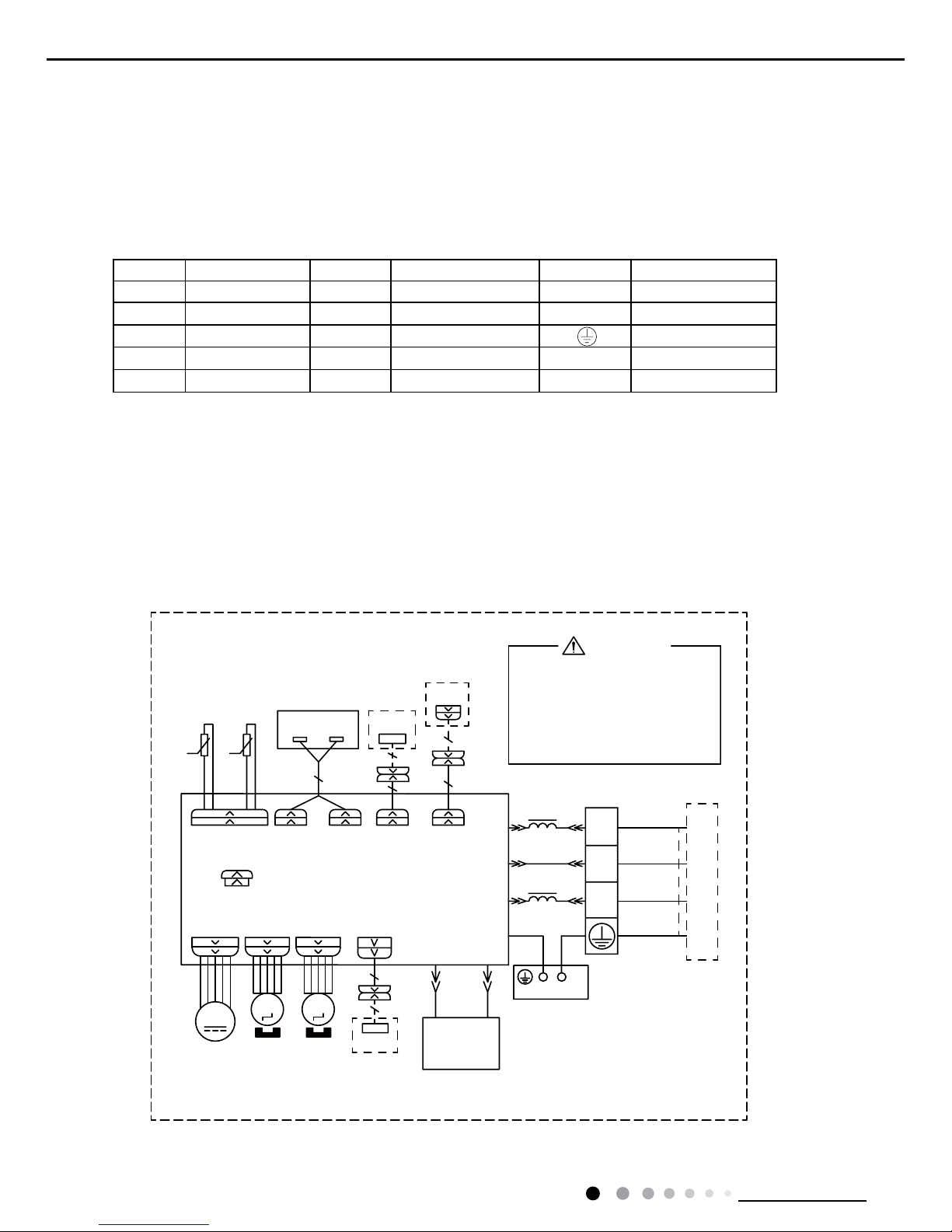
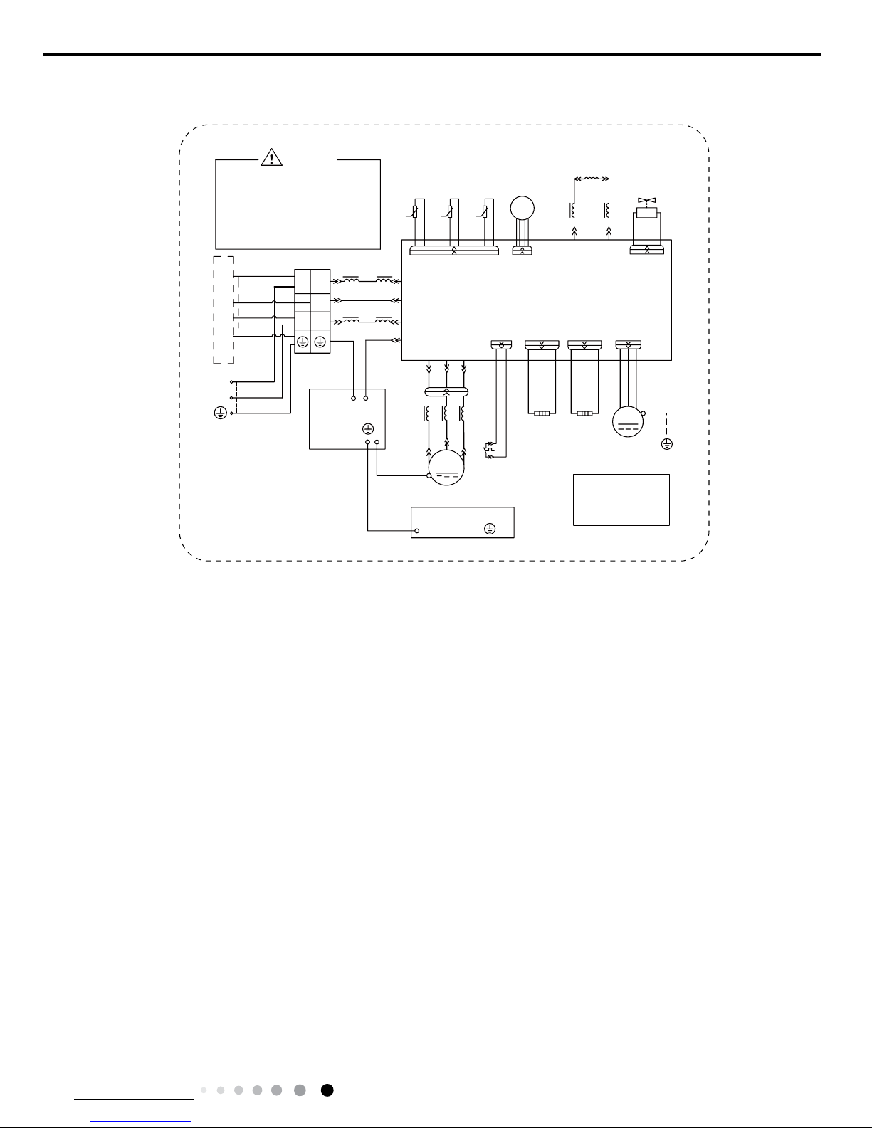
5. Electrical Part
5.1 Wiring Diagram
● Indoor Unit
● Instruction
Symbol Symbol Color Symbol Symbol Color Symbol Name
WH White GN Green CAP Jumper cap
YE Yellow BN Brown COMP Compressor
RD Red BU Blue Grounding wire
YEGN Yellow/Green BK Black / /
VT Violet OG Orange / /
Note: Jumper cap is used to determine fan speed and the swing angle of horizontal lover for this model.
60000700030904
GWH09YC-K6DNA1A/I(CB437N01600) GWH12YC-K6DNA1A/I(CB437N01100) GWH12YC-K6DNA2A/I
GWH09YC-K6DNA2A/I
67(33,1*
&$3
%/2&.
7(50,1$/
)$1
-803
$30$,1%2$5'
<(*1
%.
%1
1
1
;7
%8
$&/
&20287
&200$18$/
&211(&725
$3
:,5('
02725
287'22581,7
76(1625
',63
',63
57
$3
5220
78%(
7(036(1625
7(036(1625
',63/$<%2$5'
5(&(,9(5$1'
57
'&02725
0
6:,1*8'
0
&21752//(5
02725
&211(&7,1*
&$%/(
6:,1*/5
0
83'2:1
67(33,1*
02725
/()75,*+7
$3
:,),
:,),
02'8/(
+($/7+/+($/7+1
:$51,1*
3(
<(*1
%.
%1
%8
<(*1
0$*1(7,&
5,1*
5'
%8
&2/'3/$60$
*(1(5$725
3OHDVHGRQWWRXFKDQ\
HOHFWURQLFFRPSRQHQWDQG
WHUPLQDOZKHQWKHPDFKLQH
LVUXQQLQJVWRSSLQJRU
KDVEHHQSRZHUHGRIIIRU
OHVVWKDQPLQXWHVWR
SUHYHQWHOHFWULFVKRFN
(9$325$725
3(
'5<
&217$&7
237,21$/
'225&
$3
'5<&
/
/
13
Technical Information
Service Manual
67(33,1*
&$3
%/2&.
7(50,1$/
)$1
-803
$30$,1%2$5'
<(*1
%.
%1
1
1
;7
%8
$&/
&20287
&200$18$/
&211(&725
$3
:,5('
02725
287'22581,7
76(1625
',63
',63
57
$3
5220
78%(
7(036(1625
7(036(1625
',63/$<%2$5'
5(&(,9(5$1'
57
'&02725
0
6:,1*8'
0
&21752//(5
02725
&211(&7,1*
&$%/(
6:,1*/5
0
83'2:1
67(33,1*
02725
/()75,*+7
$3
:,),
:,),
02'8/(
+($/7+/ +($/7+1
:$51,1*
3(
<(*1
%.
%1
%8
<(*1
0$*1(7,&
5,1*
5'
%8
&2/'3/$60$
*(1(5$725
3OHDVHGRQWWRXFKDQ\
HOHFWURQLFFRPSRQHQWDQG
WHUPLQDOZKHQWKHPDFKLQH
LVUXQQLQJVWRSSLQJRU
KDVEHHQSRZHUHGRIIIRU
OHVVWKDQPLQXWHVWR
SUHYHQWHOHFWULFVKRFN
(9$325$725
3(
/
/
237,21$/
&217$&7
'5<
'225&
60000700030902
GWH12YC-K6DNA1A/I(CB437N01101) GWH09YC-K6DNA1A/I(CB437N01601)
14
Technical Information
Service Manual
RIHOHFWULFVKRFN
3OHDVHGRQWWRXFKDQ\
WHUPLQDOZKHQWKHPDFKLQHLV
UXQQLQJVWRSSLQJRUKDVEHHQ
SRZHUHGRIIIRUOHVVWKDQ
PLQXWHVWRSUHYHQWWKHULVN
:$51,1*
<(*1
%8
%.
%1
1
/
1
/
/
/
/
/
%8
%.
%1
0$*1(7,&5,1*
7(50,1$/
;7
%/2&.
1
$&/
&208
3(
&1
7(03
6(1625
7(03
6(1625
7(03
57
57
57
6(1625
N
N
N
28778%(
2875220
(;+$867
<9
:$<
:$<
9$/9(
97
97
/;
/;
/
/
5($&725
/
%8
%1
0$*1(7,&
5,1*
$30DLQ%RDUG
2)$1
)$1
0
3(
3(
<(*1
02725
3527(&725
29(5/2$'
5'
29&&203
6$7
5'
/
:
9
8
&203
&203
:
9
8
;
%8
<(
5'
0$*1(7,&
5,1*
32:(5
/
1
<(*1
%8
%1%.
<(*1
<(*1
3(
<(*1
(/(&75,&$/
%2;
3(
<(*1
%8
<(
5'
(.9
&1
(/(&7521,&
9$/9(
(;3$16,21
0,',62/$7,21
6+((7
3(
127(0RWRU
DSSOLHVWRWKH
LURQVKHOOPRWRU
JURXQGRQO\
,1'22581,7
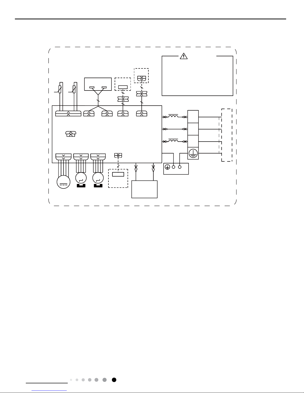
● Outdoor Unit
6361000008401
600007001110
GWH12YC-K6DNA1A/O(CB437W01101)
GWH09YC-K6DNA1A/O(CB437W01600) GWH12YC-K6DNA1A/O(CB437W01100)
,1'22581,7
RIHOHFWULFVKRFN
3OHDVHGRQWWRXFKDQ\
WHUPLQDOZKHQWKHPDFKLQHLV
UXQQLQJVWRSSLQJRUKDVEHHQ
SRZHUHGRIIIRUOHVVWKDQ
PLQXWHVWRSUHYHQWWKHULVN
:$51,1*
<(*1
%8
%.
%1
1
/
1
/
/
%8
%.
%1
0$*1(7,&5,1*
7(50,1$/
;7
%/2&.
1
$&/
&208
3(
&1
7(03
6(1625
7(03
6(1625
7(03
57
57
57
6(1625
N
N
N
28778%(
2875220
(;+$867
&1
(.9
(/(&7521,&
9$/9(
(;3$16,21
<9
:$<
:$<
9$/9(
97
97
/;
/;
/
/
5($&725
/
%8
%1
0$*1(7,&
5,1*
$30DLQ%RDUG
(+
(+
%RWWRP
%DQG
&RPS
%DQG
+HDWHU
+HDWHU
+($7 +($7
2)$1
)$1
0
3(
3(
<(*1
02725
3527(&725
29(5/2$'
5'
29&&203
6$7
5'
/
:
9
8
&203
&203
:
9
8
;
%8
<(
5'
0$*1(7,&
5,1*
32:(5
/
1
<(*1
%8
%1%.
<(*1
<(*1
3(
<(*1
(/(&75,&$/
%2;
3(
<(*1
%8
<(
5'
0,',62/$7,21
6+((7
3(
127(0RWRU
DSSOLHVWRWKH
LURQVKHOOPRWRU
JURXQGRQO\
15
Technical Information
Service Manual
6361000008404
of electric shock !
Please don't touch any
terminal when the machine is
running ,stopping or has been
powered off for less than 30
minutes to prevent the risk
WARNING
θ
θ
θ
YEGN
BU
BK
BN
N
L
N(1)
2
3
L1
L1
L2
L2
BU
BK
BN
MAGNETIC RING
TERMINAL
XT
BLOCK
N
AC-L1
COMU
PE
CN2
TEMP.
SENSOR
TEMP.
SENSOR
TEMP.
RT3
RT2
RT1
SENSOR
(20k)
(15k)
(50k)
OUTTUBE
OUTROOM
EXHAUST
CN1
EKV
ELECTRONIC
VALVE
EXPANSION
4YV
4-WAY
4WAY
VALVE
VT
VT
LX1-1
LX1-2
L3
L3
REACTOR
L
BU
BN
MAGNETIC
RING
AP:Main Board
EH1
EH2
Bottom
Band
Comp.
Band
Heater
Heater
HEAT1 HEAT2
OFAN
FAN
M
PE
PE
YEGN
MOTOR
PROTECTOR
OVERLOARD
RD
OVC-COMP
SAT
RD
L4
W
V
U
COMP.
COMP
W
V
U
X1
BU
YE
RD
MAGNETIC
RING
POWER
L
N
YEGN
BU
BN(BK)
YEGN
YEGN
PE
YEGN
ELECTRICAL
BOX
PE
MID.ISOLATION
SHEET
PE
YEGN
BU
YE
RD
NOTE:Motor
applies to the
iron shell motor.
ground only
INDOOR UNIT
These circuit diagrams are subject to change without notice, please refer to the one supplied with the unit.
GWH09YC-K6DNA1A/O(CB437W01601)
16
Technical Information
Service Manual
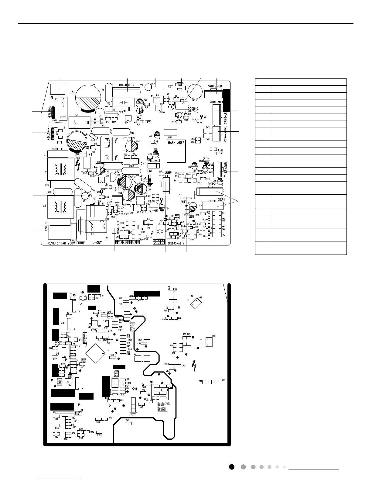
5.2 PCB Printed Diagram
Indoor Unit
● Top view
● Bottom view
8
91
5
11
12
10
13
14
18
5
6
7
1216 1734
No. Name
1 Neutral wire
2 Needle stand for indoor fan
3 Auto button
4 Up&down swing motor
5 left&right swing motor
6 Interface of temperature sensor
7
Terminal for display board
connection
8 Terminal of jumper cap
9 Communication wire
10
Connect earthing wire(only for
the mode with this function)
11 Fuse
12 Live wire interface
13
Interface of health function
neutral wire
14
Interface of health function live
wire
15 Detecting plate(WIFI )
16
Connect earthing wire(only for
the mode with this function)
17
Wired controller (only for the
mode with this function)
18
Interface of gate control (only
for the mode with this function)
17
Technical Information
Service Manual
● Top view
Outdoor Unit
● Bottom view
No. Name
1 Compressor
2 Reactor 2
3 Reactor 1
4 Chassis electric heating
5 Compressor electric heating
6 4-way valve
7 DC fan
8 Earthing wire
9
Communication wire
10 Neutral wire
11 Live wire
12 Electronic expansion valve
13 Temperature sensor
14 Overloard
15 Dred
4
5
6
7
8
9
10
11
1
2
3
12131415
18
Technical Information
Service Manual
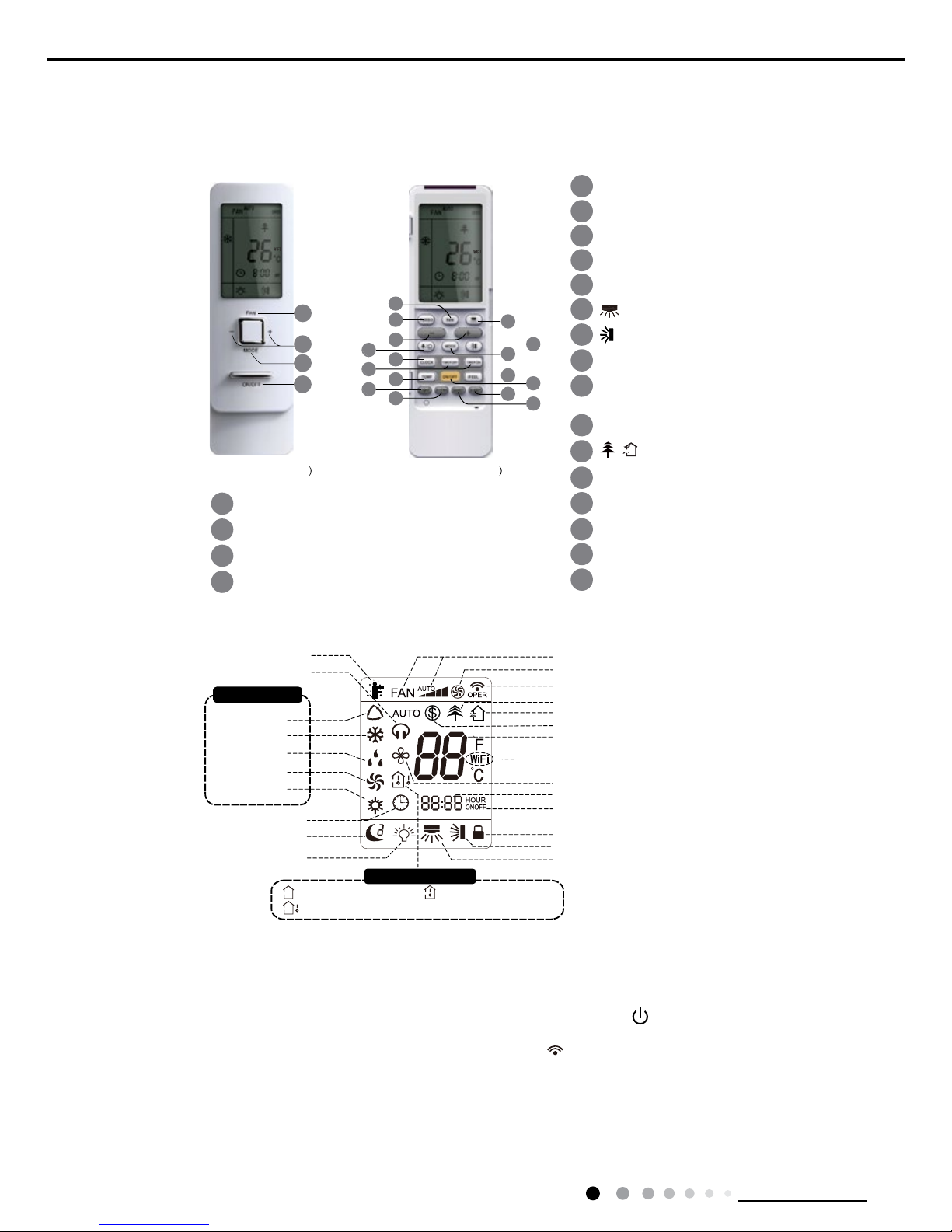
6. Function and Control
6.1 Remote Controller Introduction
Buttons on Remote Controller
Introduction
for Icons on Display Screen
Introduction for Buttons on Remote Controller
Note:
●
After putting through the power, the air conditioner will give out a sound.Operation indic
●
This is a general use remote controller, it could be used for the air conditioners with multifunction; For some function, which the model
don't have, if press the corresponding button on the remote controller that the unit will keep the original running status
.
ator " " is ON (red indicator). A
fter that, you can
operate the air conditioner by using remote controlle
r.
● Under on status, pressing the button on the remote controller
, the signal icon " " on the display of remote controller will blink once and
the air conditioner will give out a “de” sound, which means the signal has been sent to the air conditioner
.
● Under of
f status, set temperature and clock icon will be displayed on the display of remote controller (If timer on, timer off and light
functions are set, the corresponding icons will be displayed on the display of remote controller at the same time); Under on st
atus, the
display will show the corresponding set function icons.
1. ON/OFF button
Press this button, the unit will be turned on, press it once more, the unit will be turned off. Sleep function will be canceled, while unit off.
1
2
3
4
5
6
7
8
9
10
11
12
button
button
X-FAN button
QUIET button
SLEEP button
TEMP button
I FEEL button
13
14
15
16
TURBO button
LIGHT button
button
TIMER ON/
TIMER OFF button
CLOCK button
1
2
3
4
ON/OFF button
FAN button
+/- button
MODE button
ON/OFF button
FAN button
+/- button
MODE button
3
4
2
1
(before opening cover (after opening cover
/
15
5
2
6
3
12
16
4
11
8
9
13
7
1
10
14
Send signal
Turbo mode
8ć heating function
Set temperature
Set time
X-FAN function
TIMER ON /TIMER OFF
Child lock
Up & down swing
Left & right swing
Set fan speed
Light
Temp. display type
: Set temp.
: Outdoor ambient temp.
: Indoor ambient temp.
Sleep mode
Clock
Heat mode
Fan mode
Dry mode
Cool mode
Auto mode
Operation mode
I feel
Healthy mode
Scavenging functions
Quiet
This is a general remote controller. Some
models have this function while some do
not. Please refer to the actual models.
19
Technical Information
Service Manual
2. FAN button
Press this button,
Auto, Low, Medium-low, Medium, Medium-high, High speed can be circularly selected. After powered on, Auto fan speed
is default. Under DR
Y mode, Low fan speed only can be set up.
3. MODE button
Press this button,
Auto, Cool, Dry, Fan, Heat mode can be selected circularly. Auto mode is default while power on. Under Auto mode, the
temperature will not be displayed;Under Heat mode, the initial value is 28°C( 82°F);Under other modes, the initial value is 25°
C(77°F).
4. +/- button
● Presetting temperature can be increased.
Press this button,the temperature can be set up, continuously press this button and hold for two seconds, the relative contents
can quickly
change,until unhold this button and send the order that the °C(°F) signal will be displayed all the time.The temperature adjust
ment is
unavilable under the
Auto mode, but the order can be sent by if pressing this button.Temperature of Celsius degree setting:16-30;for
Fahrenheit degree setting:61-86.
● Presetting temperature can be decreased.
Press this button, the temperature can be set up, continuously press this button and hold for two seconds, the relative content
s can quickly
change,until unhold this button and send the order that the °C(°F) signal will be displayed all the time.The temperature adjust
ment is
unavailable under the
Auto mode,but the order can be sent by if pressing this button.
5. TURBO button
Under Cool or Heat mode,press this button can turn on or turn of
f the Turbo function.After the Turbo function turned on, the signal of Turbo
will displa
y. The signal will be automatically cancelled if changing the mode or fan speed.
6. button
7KLVIXQFWLRQLVRQO\DYDLODEOHIRUVRPHPRGHOV
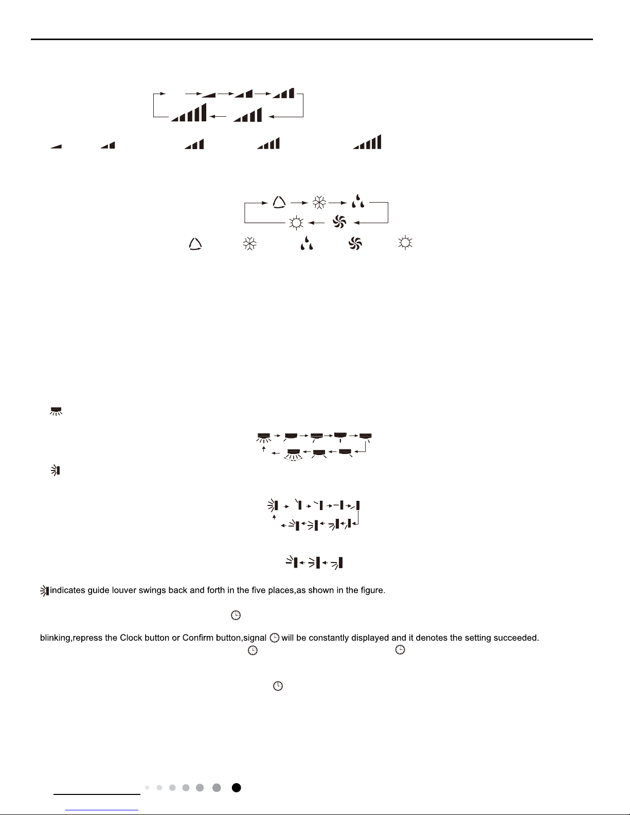
Press this button to set left & right swing angle cycling as below:
7. button
Press this button to set swing angle,which circularly changes as below
:
This remote controller is universal. If it receives threes kinds of following status,the swing angle will remain origial.
If guide louver is stopped when it is swinging up and down,it will remain its present position.
8. CLOCK button
Press this button, the clock can be set up,signal blink and displa
y.Within 5 seconds, the value can be adjusted by pressing + or - button,
if continuously press this button for 2 seconds above,in every 0.5 seconds, the value on ten place of Minute will be increased
1.During
After
powered on, 12:00 is defaulted to display and signal will be displayed. If there is signal be displayed that denotes
the current time
value is Clock value, otherwise is
Timer value.
9. TIMER ON/TIMER OFF button
●
Timer On setting: Signal “ON”will blink and display,signal will conceal,the numerical section will become the timer on setting status.
During 5 seconds blink,by pressing + or - button to adjust the time value of numerical section,every press of that button,the v
alue will be
increased or decreased 1 minute.Hold pressing + or - button,2 seconds late
r,it quickly change,the way of change is: During the initial 2.5
seconds,ten numbers change in the one place of minute,then the one place is constant,ten numbers change in the ten splace of m
inute at
2.5 seconds speed and carry
. During 5s blink,press the Timer button,the timer setting succeeds.The Timer On has been set up,repress the
timer button,theT
imer On will be canceled. Before setting theTimer,please adjust the Clock to the current actual time.
● One press this key to enter into TIMER OFF setup, in which case the TIMER OFF icon will blink. The method of setting is the sameas for
Note: It’s Low fan speed
under Dry mode.
(only for cooling and heating unit.
As for cooling only unit, it won’t
have any action when it receives
the signal of heating operation.)
Medium fanLow fan High fan
Medium-low fan Medium-high fan
ATUO
AUTO COOL DRY FAN HEAT
OFF
OFF
20
Technical Information
Service Manual
TIMER ON.
10. TEM
P button
Press this button,the following temperature can be setted circularly: the setting temperature, indoor ambient temperature and
outdoor
to ,displaying the indoor ambient temperature. is the outdoor ambient temperature. 3s laterit will return to the setti
ng temprature or it
depends on the other received signal within3s.
Note: Outdoor ambient temperatue display range is 0~60°C (32~99°F).
As for the outdoor ambient temperature below 0it displays 0°C(32°F).
W
arm tips: When operating buttons on the cover, please make sure the cover is closed completely.
1
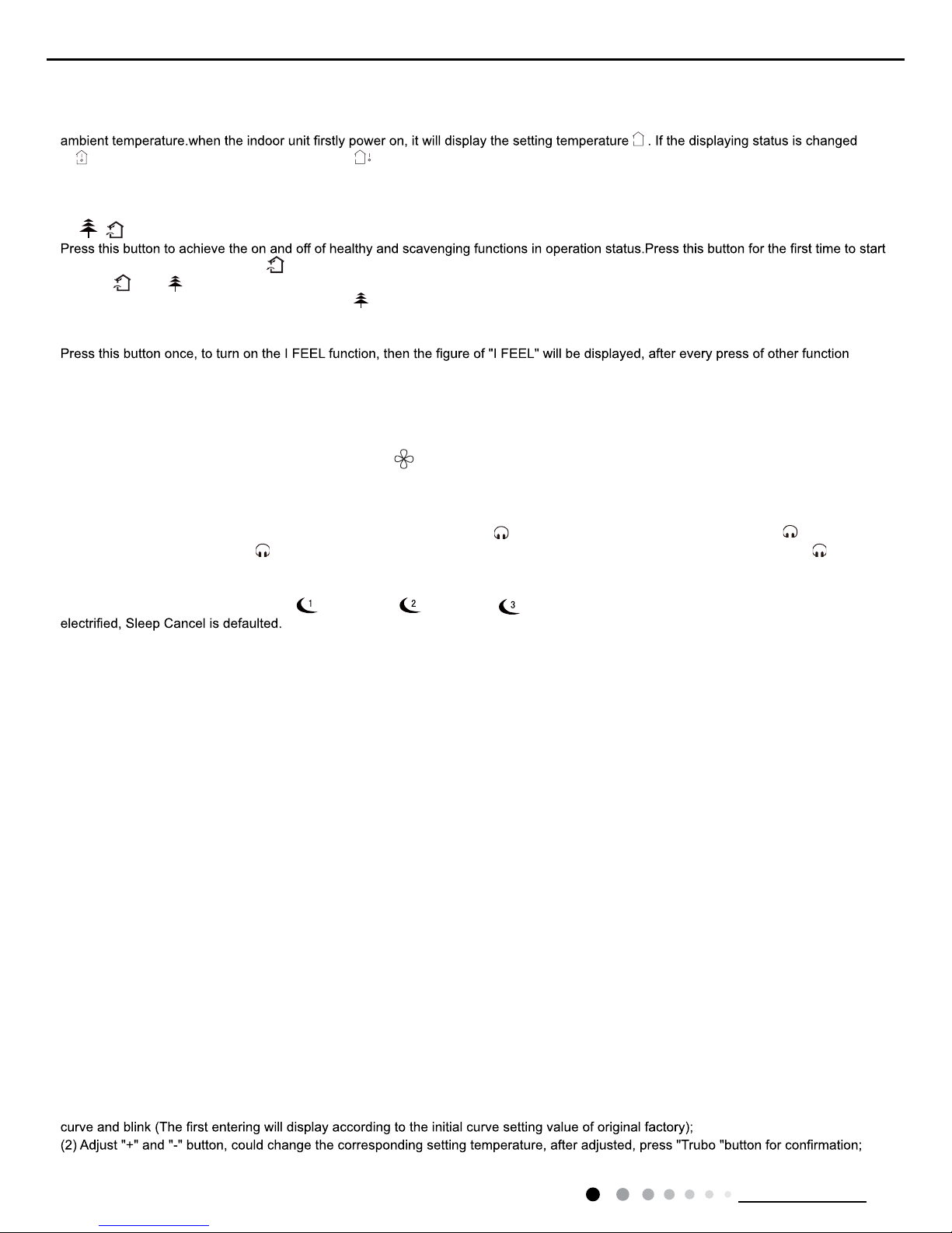
1. / button(This function is only available for some models)
scavenging function;LCD displays“ ”.Press the button for the second time to start healthy and scavenging functions simultan
eously;LCD
displays“ ”and “ ” .Press this button for the third time to quit healthy and scavenging functions simultaneously
.Press the button for the
fourth time to start healthy function; LCD display“ ” .Press this button again to repeat the operation above
.
NOTE: This function is applicable to partial of models.
12. I FEE
L button
button, every 200ms to send I FEE
L once, after this function started,the remote control will send temperature to the main un it in every 10
minutes.When repress this button, this function will be turned of
f.
13. LIGHT button
Press this button at unit On or Of
f status,Light On and Light Off can be set up.After powered on, Light On is defaulted.
14. X-F
AN button
Pressing X-F
AN button in COOL or DRY mode,the icon is displayed and the indoor fan will continue operation for 2 minutes in order
to dry the indoor unit even though you have turned of
f the unit.After energization, X-FAN OFF is defaulted.X-FAN is not available in
A
UTO,FAN or HEAT mode.
15. QUIET button
Press this button,the Quiet status is under the
Auto Quiet mode (display" " and “Auto”signal ) and Quiet mode(display " " singal) and
Quiet OFF(there is no signal of " " displayed),after powered on,the Quiet OFF is defaulted. Under the Quiet mode (Display
" "signal),
the fan speed is not available.
16. SLEE
P button
●Press this button, can select Sleep 1 ( ), Sleep 2 ( ),Sleep 3 ( ) and cancel the Sleep, circulate be
tween these, after
●Sleep 1 is Sleep mode 1, in Cool, Dehumidify modes: sleep status after run for one hour
, the main unit setting temperature will increase 1°C,
2 hours,setting temperature increased 2°C, the unit will run at this setting temperature; In Heat mode: sleep status after run
for one hour,
the setting temperature will decrease 1°C, 2 hours, setting temperature will decrease 2°C, then the unit will run at this sett
ing temperature.
●Sleep 2 is sleep mode 2, that is air conditioner will run according to the presetting a group of sleep temperature curve.
In Cool mode:
(1) When setting the initial temperature 16~23°C, after turned on Sleep function, the temperature will be increased 1°C in ever
y hour,after
3°C the temperature will be maintained, after 7hours,the temperature will be decreased 1°C, after that the unit will keep on ru
nning under
this temperature;
(2) When setting the initial temperature 24~27°C, after turned on Sleep function, the temperature will be increased 1°C in ever
y hour,after
2°C the temperature will be maintained, after 7hours,the temperature will be decreased 1°C, after that the unit will keep on ru
nning under
this temperature;
(3) When setting the initial temperature 28~29°C, after turned on Sleep function, the temperature will be increased 1°C in ever
y hour, after
1°C the temperature will be maintained, after 7hours,the temperature will be decreased 1°C, after that the unit will keep on ru
nning under
this temperature;
(4) When setting the initial temperature 30°C, under this temperature setting, after 7hours, the temperature will be decreased
1°C, after
that the unit will keep on running under this temperature;
In Heat mode:
(1) Under the initial presetting temperature 16°C, it will run under this setting temperature all along.
(2) Under the initial presetting temperature17~20°C, after Sleep function started up, the temperature will decrease 1°C in ever
y hour, after
1°C decreased, this temperature will be maintained.
(3) Under the initial presetting temperature 21~27°C, after Sleep function started up, the temperature will decrease 1°C in ev
ery hour,after
2°C decreased, this temperature will be maintained.
(4) Under the initial presetting temperature 28~30°C, after Sleep function started up, the temperature will decrease 1°C in ev
ery hour, after
3°C decreased, this temperature will be maintained
●Sleep 3- the sleep curve setting under Sleep mode by DI
Y:
(1) Under Sleep 3 mode, press "T
urbo" button for a long time, remote control enters into user individuation sleep setting status, at this time,
the time of remote control will display "1hour ", the setting temperature "88" will display the corresponding temperature of la
st setting sleep
(3)
At this time, 1hour will be automatically increased at the timer postion on the remote control, (that are "2hours" or "3hou
rs" or "8hours "),
21
Technical Information
Service Manual
the place of setting temperature "88" will display the corresponding temperature of last setting sleep curve and blink;
control will resume the original timer display;temperature display will resume to original setting temperature.
●Sleep3- the sleep curve setting under Sleep mode by DI
Y could be inquired:
The user could accord to sleep curve setting method to inquire the presetting sleep curve, enter into user individuation sleep setting status,
Note: In the above presetting or enquiry procedure, if continuously within10s, there is no button pressed, the sleep curve sett
ing status will
be automatically quit and resume to display the original displaying. In the presetting or enquiry procedure, press "ON/OFF" but
ton, "Mode"
button, "T
imer" button or "Sleep" button, the sleep curve setting or enquiry status will quit similarly.
17.
About X-FAN function
This function indicates that moisture on evaporator of indoor unit will be blowed after the unit is stopped to avoid mould.
(1)Having set X-F
AN function on: After turning off the unit by pressing ON/OFF button indoor fan will continue running for about 2 min. at
low speed. In this period, press X-F
AN button to stop indoor fan directly.
(2)Having set X-F
AN function off: After turning off the unit by pressing ON/OFF button, the complete unit will be off directly.
18.
About AUTO RUN
When
AUTO RUN mode is selected, the setting temperature will not be displayed on the LCD, the unit will be in accordance with the room
temp. automatically to select the suitable running method and to make ambient comfortable.
19.
About turbo function
If start this function, the unit will run at super-high fan speed to cool or heat quickly so that the ambient temp. approachs
the preset temp.
as soon as possible.
20.
About lock
Press + and - buttons simultaneously to lock or unlock the keyboard. If the remote controlleris locked, the icon will be
displayed on it, in
.
21.
About swing up and down
(1)Press swing up and down button continuously more than 2s,the main unit will swing back and forth from up to down, and then
loosen
the button, the unit will stop swinging and present position of guide louver will be kept immediately
.
(2)Under swing up and down mode, when the status is switched from of
f to , if press this button again 2s later, status will switch to off
status directly; if press this button again within 2s,the change of swing status will also depend on the circulation sequence
stated above.
22.
About swing left and right(This function is only available for some models)
(1)Press swing left and right button continuously more than 2s,the main unit will swing back and forth from left to right, and
then loosen the
button, the unit will stop swinging and present position of guide louver will be kept immediately
.
(2)2. Under swing left and right mode, when the status is switched from of
f to , if press this button again 2s later, status will switch to
of
f status directly; if press this button again within 2s,the change of swing status will also depend on the circulation sequence stated above.
23.
About switch between Fahrenheit and Centigrade
Under status of unit of
f, press MODE and - buttons simultaneously to switch °C and °F.
24. Combination of " TEMP" and "CLOCK" buttons :
About Energy-saving Function
Press “TEMP” and “CLOCK” simultaneously in COOL
mode to start energy-saving function.Nixie tube on the remote controller displa
ys “SE”.
Repeat the operation to quit the function.
25. Combination of " TEMP" and "CLOCK" buttons :
About 8°C Heating Function(This function is only available for some models)
Press “TEMP” and “CLOCK” simultaneously in HE
AT mode to start 8°C Heating Function.Nixie tube on the remote controller displays"
"and a selected temperature of “8°C” (46°F if Fahrenheit is adopted). Repeat the operation to quit the function.
26.
About Auto Quiet function
When auto quiet function is selected:
(1)Under cooling mode: indoor fan operates at notch 4 speed. 10 minutes later or when indoor ambient temperature≤28°C, indoor
fan will
operate at notch 2 speed or quiet mode according to the comparison between indoor ambinet temperature and set temperature.
(2)Under heating mode: indoor fan operates at notch 3 speed or quiet mode according to the comparison between indoor ambient
temperature and set temperature.
(3)Under dr
y, fan mode: indoor fan operates at quiet mode.
(4)Under auto mode: the indoor fan operates at the auto quiet mode according to actual cooling, heating or fan mode.
27.
About Sleep function
28.
WIFI Function
WIFI
Under the Fan and
Auto mode, the Sleep function cannot be set up, under Dehumidify mode, only Sleep 1 can be selected.Select and
enter into any kind of Sleep mode, the Quiet function will be attached and stared, dif
Press "MODE" and "TURBO" button simultaneously to turn on or turn off WIFI function. When WIFI function is turned on, the "
" icon
will be displayed on remote controller; Long press "MODE" and "TURBO" buttons simultaneously for 10s, remote controller will se
nd WIFI
reset code and then the WIFI function will be turned on. WIFI function is defaulted ON after energization of the remote contro
ller.(This
function only applicable for some models.)
ferent Quiet status could be optional and turned off.
22
Technical Information
Service Manual
Operation Guide
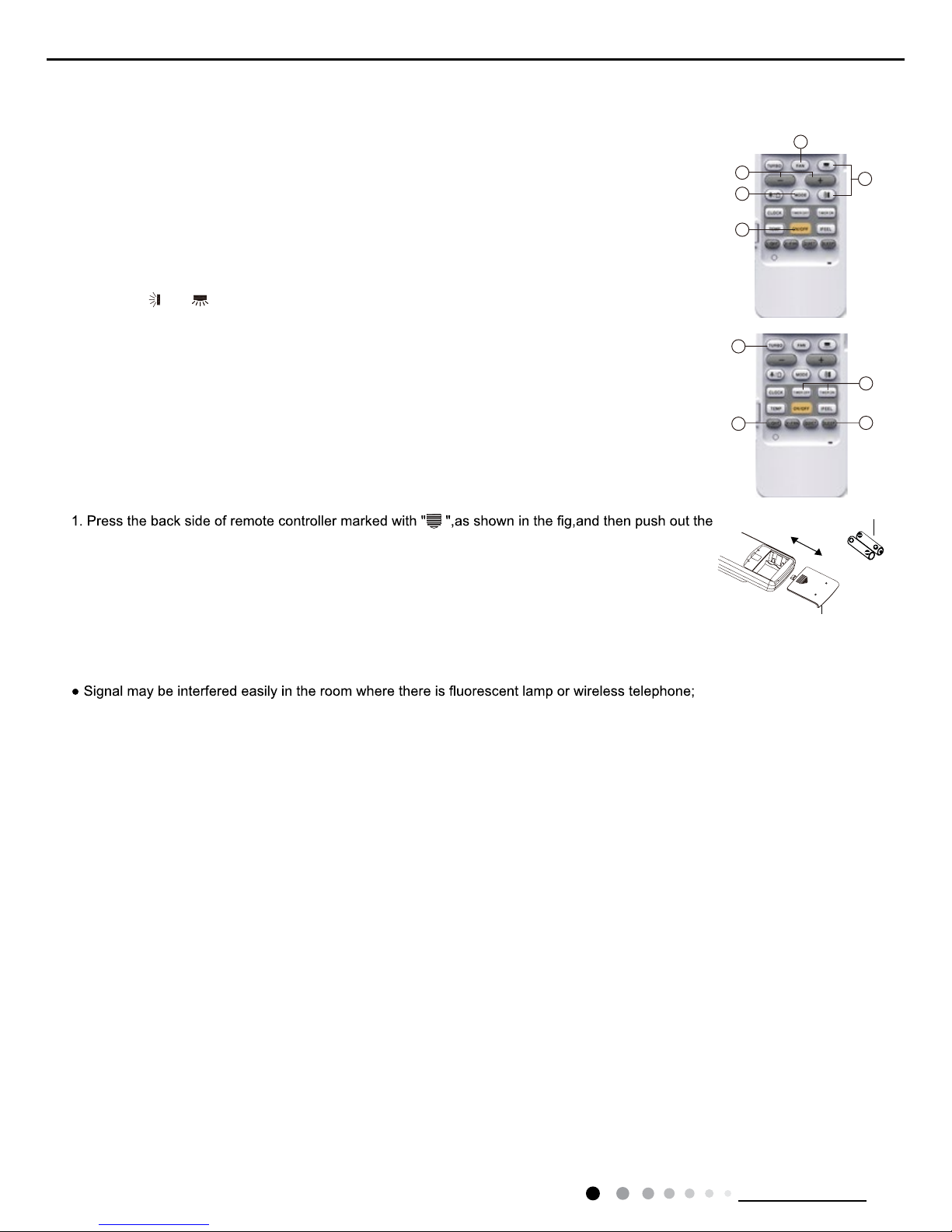
Replacement of Batteries in Remote Controller
1. General operation
(1)After powered on, press ON/OFF button, the unit will start to run. (Note: When it is powered on, the
guide louver of main unit will close automaticall
y.)
(2)Press MODE button, select desired running mode.
(3)Pressing + or - button, to set the desired temperature (It is unnecessary to set the temp. at
AUTO
mode.)
(4)Pressing F
AN button, set fan speed, can select AUTO FAN,LOW, MEDIUM-LOW, MEDIUM, MEDIUM-
HIGH and HIGH.
2. Optional operation
(1)Press SLEE
P button, to set sleep.
(2)Press
TIMER ON and TIMER OFF button, can set the scheduled timer on or timer off.
(3)Press LIGH
T button, to control the on and off of the displaying part of the unit (This function may be not
available for some units).
(4)Press
TURBO button, can realize the ON and OFF of TURBO function.
cover of battery box along the arrow direction.
2. Replace two 7# (AAA 1.5V) dry batteries, and make sure the position of "+" polar and "-" polar are
correct.
3. Reinstall the cover of battery box.
Note:
● During operation, point the remote control signal sender at the receiving window on indoor unit.
● The distance between signal sender and receiving window should be no more than 8m, and there
should be no obstacles between them.
remote controller should be close to indoor unit during operation.
● Replace new batteries of the same model when replacement is required.
● When you don’t use remote controller for a long time, please take out the batteries.
● If the display on remote controller is fuzzy or there’s no display, please replace batteries.
5
1
2
3
4
(5)
Pressing and button, to select the swing.
battery
Cover of battery box
remove
reinstall
1
2
3
4

23
Technical Information
Service Manual
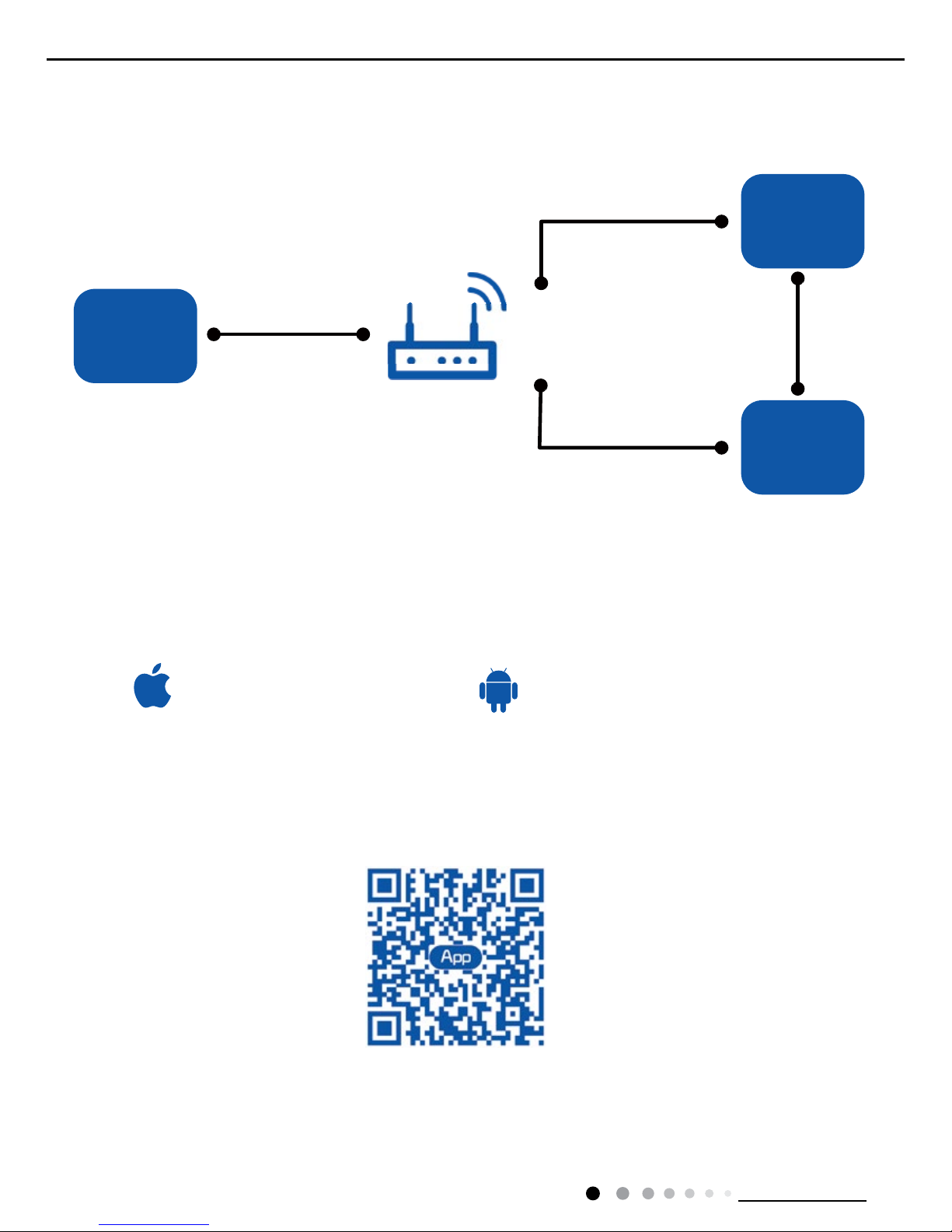
6.2 GREE+ App Operation Manual
Control Flow Chart
Download and installation
Operating Systems
Requirement for User's smart phone:
Scan the QR code or search "GREE+" in the application market to download and install it. When "GREE+" App is installed, register the
account and add the device to achieve long-distance control and LAN control of Gree smart home appliances.
For more information, please refer to "Help" in App.
Internet
Cellular/
Other Wi-FI
Home Wi-Fi
Home wireless router
Home Wi-Fi
Gree
Gree Cloud
GREE+ APP
intelligent
home
appliances
iOS system
Support iOS7.0 and
above version
Android system
Support Android 4.0 and
above version
GREE+ App Download Linkage
24
Technical Information
Service Manual
Control Flow Chart
Download and installation
Operating Systems
Requirement for User's smart phone:
Scan the QR code or search "Ewpe Smart" in the application market to download and install it. When "Ewpe Smart" App is installed,
register the account and add the device to achieve long-distance control and LAN control of smart home appliances.
For more information, please refer to "Help" in App.
6.3 Ewpe Smart App Operation Manual
iOS system
Support iOS7.0 and
above version
Android system
Support Android 4.0 and
above version
App Download Linkage
Internet
Cellular/
Other Wi-FI
Home Wi-Fi
Home wireless router
Home Wi-Fi
Cloud
APP
intelligent
home
appliances
 Loading...