

Gree GWH12UB-K3DNA4F, GWH09UB-K3DNA4F, GWH18UC-K3DNA4F Service Manual

GREE ELECTRIC APPLIANCES,INC.OF ZHUHAI
Change for Life
Service Manual
Models: GWH09UB-K3DNA4F
GWH12UB-K3DNA4F
GWH18UC-K3DNA4F
(Refrigerant R410A)

Table of Contents
Service Manual
Table of Contents
Part
Ⅰ
: Technical Information
.......................................................................1
1. Summary
......................................................................................................................1
2. Specications
..........................................................................................................2
2.1 Specication Sheet ...........................................................................................................2
2.2 Operation Characteristic Curve ........................................................................................8
2.3 Capacity Variation Ratio According to Temperature .........................................................9
2.4 Cooling and Heating Data Sheet in Rated Frequency ...................................................10
2.5 Noise Curve ....................................................................................................................10
3. Outline Dimension Diagram
...................................................................... 11
3.1 Indoor Unit ...................................................................................................................... 11
3.2 Outdoor Unit ...................................................................................................................12
4. Refrigerant System Diagram
....................................................................13
5. Electrical Part
.........................................................................................................14
5.1 Wiring Diagram ...............................................................................................................14
5.2 PCB Printed Diagram .....................................................................................................17
6. Function and Control
......................................................................................21
6.1 Remote Controller Introduction .....................................................................................21
6.2 Operation of Smart Control (Smart Phone, Tablet PC) ..................................................26
6.3 Brief Description of Modes and Functions ......................................................................31
Part
Ⅱ
: Installation and Maintenance
.................................................40
7. Notes for Installation and Maintenance
..........................................40
8. Installation
................................................................................................................42
8.1 Installation Dimension Diagram ......................................................................................42
8.2 Installation Parts-checking ............................................................................................44
8.3 Selection of Installation Location ....................................................................................44
8.4 Electric Connection Requirement ...................................................................................44
8.5 Installation of Indoor Unit ................................................................................................44
8.6 Installation of Outdoor Unit .............................................................................................47
8.7 Vacuum Pumping and Leak Detection ...........................................................................48
8.8 Check after Installation and Test Operation ...................................................................48

Table of Contents
Service Manual
9. Maintenance
............................................................................................................49
9.1 Error Code List ...............................................................................................................49
9.2 Procedure of Troubleshooting ........................................................................................56
9.3 Troubleshooting for Normal Malfunction .........................................................................80
10. Exploded View and Parts List
..............................................................82
10.1 Indoor Unit ....................................................................................................................82
10.2 Outdoor Unit .................................................................................................................86
11. Removal Procedure
.......................................................................................90
11.1 Removal Procedure of Indoor Unit ...............................................................................90
11.2 Removal Procedure of Outdoor Unit ............................................................................99
Appendix:
......................................................................................................................110
Appendix 1: Reference Sheet of Celsius and Fahrenheit ..................................................110
Appendix 2: Conguration of Connection Pipe ...................................................................110
Appendix 3: Pipe Expanding Method ................................................................................. 111
Appendix 4: List of Resistance for Temperature Sensor ....................................................112
1
Technical Information
Service Manual
1. Summary
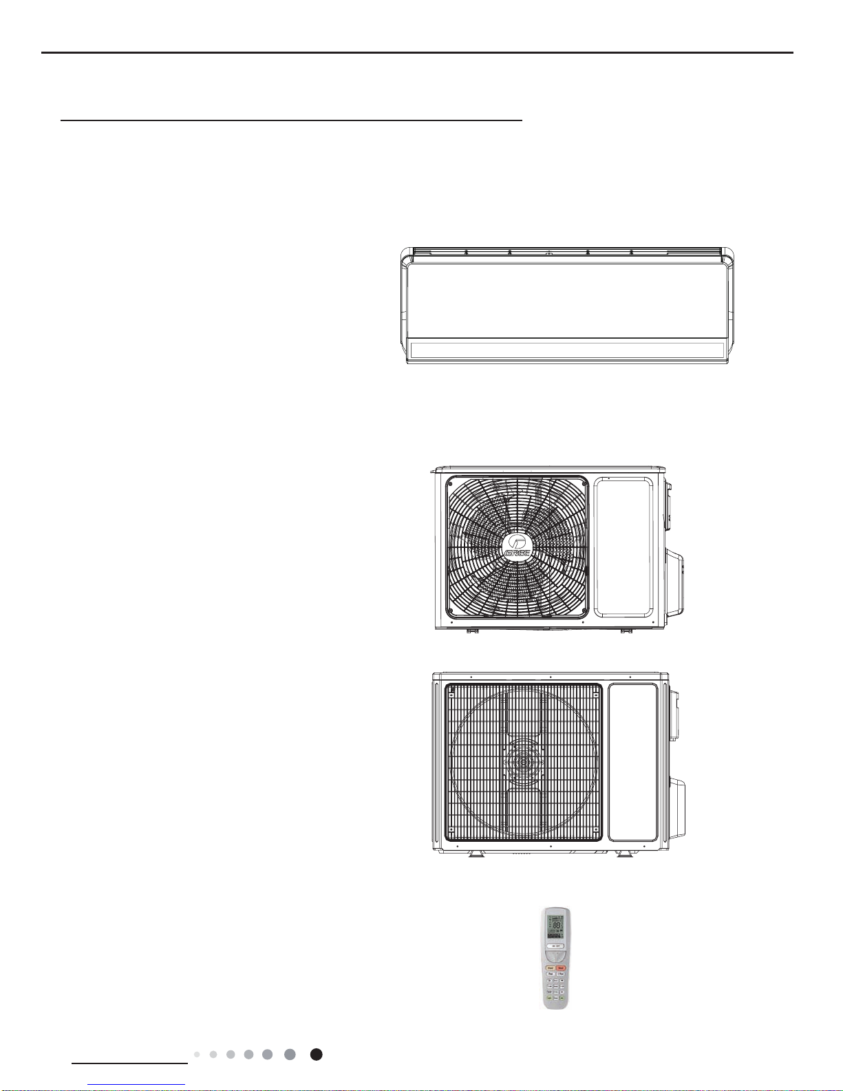
Indoor Unit:
Outdoor Unit:
Remote Controller:
Part
Ⅰ
: Technical Information
GWH09UB-K3DNA4F/O
GWH12UB-K3DNA4F/O
GWH18UC-K3DNA4F/O
SAA1FB1
GWH09UB-K3DNA4F/I(Cold Plasma)
GWH12UB-K3DNA4F/I(Cold Plasma)
GWH18UC-K3DNA4F/I(Cold Plasma)
2
Technical Information
Service Manual
2. Specications
2.1 Specication Sheet
Parameter Unit Value
Model GWH09UB-K3DNA4F
Product Code CB264000600
Power
Supply
Rated Voltage V~ 220-240
Rated Frequency Hz 50
Phases 1
Power Supply Mode Outdoor
Cooling Capacity W 2600
Heating Capacity W 3000
Cooling Power Input W 600
Heating Power Input W 800
Cooling Power Current A 2.7
Heating Power Current A 3.5
Rated Input W 1630
Rated Current A 6.5
Air Flow Volume (SH/H/MH/M/ML/L/SL) m
3
/h 650/530/470/400/350/300/290
Dehumidifying Volume L/h 0.8
EER W/W 4.33
COP W/W 3.75
SEER 7.5
SCOP 4.6
Application Area m
2
12-18
Indoor Unit
Model GWH09UB-K3DNA4F/I(Cold Plasma)
Product Code CB264N00600
Fan Type Cross-ow
Diameter Length(DXL) mm Ф92X616
Fan Motor Cooling Speed (SH/H/MH/M/ML/L/SL/Q) r/min 1350/1127/1000/870/780/690/600/550
Fan Motor Heating Speed (SH/H/MH/M/ML/L/SL/Q) r/min 1350/1151/1074/1000/930/870/842/-
Output of Fan Motor W 10
Fan Motor RLA A 0.3
Fan Motor Capacitor μF /
Input of Heater W /
Evaporator Form Aluminum Fin-copper Tube
Pipe Diameter mm Ф7
Row-n Gap mm 2-1.5
Coil Length (LXDXW) mm 623X25.4X304.8
Swing Motor Model MP24HD
Output of Swing Motor W 1.5
Fuse A 3.15
Sound Pressure Level (SH/H/MH/M/ML/L/SL) dB (A) 41/37/35/33/30/22/19
Sound Power Level (SH/H/MH/M/ML/L/SL) dB (A) 56/50/48/46/43/35/32
Dimension (WXHXD) mm 860X305X170
Dimension of Carton Box (LXWXH) mm 932X385X280
Dimension of Package (LXWXH) mm 935X388X295
Net Weight kg 12.5
Gross Weight kg 15
3
Technical Information
Service Manual
The above data is subject to change without notice; please refer to the nameplate of the unit.
Outdoor Unit
Model GWH09UB-K3DNA4F/O
Product Code CB264W00600
Compressor Manufacturer/Trademark ZHUHAI LANDA COMPRESSOR CO.,LTD.
Compressor Model QXAT-B121zE070
Compressor Oil FV50S
Compressor Type Rotary
L.R.A. A 35
Compressor RLA A 6.7
Compressor Power Input W 1430
Overload Protector 1NT11L-6233
Throttling Method Electron expansion valve
Operation temp °C 16~30
Ambient temp (cooling) °C -18~54
Ambient temp (heating) °C -30~24
Condenser Form Aluminum Fin-copper Tube
Pipe Diameter mm Ф7
Rows-n Gap mm 2.5-1.4
Coil Length (LXDXW) mm 763X57X550
Fan Motor Speed rpm 780
Output of Fan Motor W 30
Fan Motor RLA A 0.24
Fan Motor Capacitor μF /
Air Flow Volume of Outdoor Unit m
3
/h 2400
Fan Type Axial-ow
Fan Diameter mm Ф438
Defrosting Method Automatic Defrosting
Climate Type T1
Isolation I
Moisture Protection IP24
Permissible Excessive Operating
Pressure for the Discharge Side
MPa 4.3
Permissible Excessive Operating
Pressure for the Suction Side
MPa 2.5
Sound Pressure Level (H/M/L) dB (A) 50/-/-
Sound Power Level (H/M/L) dB (A) 59/-/-
Dimension (WXHXD) mm 899X596X378
Dimension of Carton Box (LXWXH) mm 945X417X630
Dimension of Package (LXWXH) mm 948X420X645
Net Weight kg 43
Gross Weight kg 46
Refrigerant R410A
Refrigerant Charge kg 1.3
Connection
Pipe
Length m 5
Gas Additional Charge g/m 20
Outer Diameter Liquid Pipe mm Ф6
Outer Diameter Gas Pipe mm Ф12
Max Distance Height m 10
Max Distance Length m 15
Note: The connection pipe applies metric diameter.

4
Technical Information
Service Manual
Parameter Unit Value
Model GWH12UB-K3DNA4F
Product Code CB264000700
Power
Supply
Rated Voltage V~ 220-240
Rated Frequency Hz 50
Phases 1
Power Supply Mode Outdoor
Cooling Capacity W 3500
Heating Capacity W 3600
Cooling Power Input W 920
Heating Power Input W 970
Cooling Power Current A 4.1
Heating Power Current A 4.2
Rated Input W 1680
Rated Current A 6.8
Air Flow Volume (SH/H/MH/M/ML/L/SL) m
3
/h 720/550/490/420/370/320/290
Dehumidifying Volume L/h 1.4
EER W/W 3.80
COP W/W 3.71
SEER 7.0
SCOP 4.6
Application Area m
2
16-24
Indoor Unit
Model GWH12UB-K3DNA4F/I(Cold Plasma)
Product Code CB264N00700
Fan Type Cross-ow
Diameter Length(DXL) mm Ф92X616
Fan Motor Cooling Speed (SH/H/MH/M/ML/L/SL/Q) r/min 1400/1185/1053/920/829/741/650/550
Fan Motor Heating Speed (SH/H/MH/M/ML/L/SL/Q) r/min 1400/1185/1119/1053/958/870/842/-
Output of Fan Motor W 10
Fan Motor RLA A 0.3
Fan Motor Capacitor μF /
Input of Heater W /
Evaporator Form Aluminum Fin-copper Tube
Pipe Diameter mm Ф7
Row-n Gap mm 2-1.5
Coil Length (LXDXW) mm 623X25.4X304.8
Swing Motor Model MP24HD
Output of Swing Motor W 1.5
Fuse A 3.15
Sound Pressure Level (SH/H/MH/M/ML/L/SL) dB (A) 43/38/36/34/31/23/20
Sound Power Level (SH/H/MH/M/ML/L/SL) dB (A) 57/51/49/47/44/36/33
Dimension (WXHXD) mm 860X305X170
Dimension of Carton Box (LXWXH) mm 932X385X280
Dimension of Package (LXWXH) mm 935X388X295
Net Weight kg 12.5
Gross Weight kg 15

5
Technical Information
Service Manual
The above data is subject to change without notice; please refer to the nameplate of the unit.
Outdoor Unit
Model GWH12UB-K3DNA4F/O
Product Code CB264W00700
Compressor Manufacturer/Trademark ZHUHAI LANDA COMPRESSOR CO.,LTD.
Compressor Model QXAT-B121zE070
Compressor Oil FV50S
Compressor Type Rotary
L.R.A. A 35
Compressor RLA A 6.7
Compressor Power Input W 1430
Overload Protector 1NT11L-6233
Throttling Method Electron expansion valve
Operation temp °C 16~30
Ambient temp (cooling) °C -18~54
Ambient temp (heating) °C -30~24
Condenser Form Aluminum Fin-copper Tube
Pipe Diameter mm Ф7
Rows-n Gap mm 2.5-1.4
Coil Length (LXDXW) mm 763X57X550
Fan Motor Speed rpm 780
Output of Fan Motor W 30
Fan Motor RLA A 0.24
Fan Motor Capacitor μF /
Air Flow Volume of Outdoor Unit m
3
/h 2400
Fan Type Axial-ow
Fan Diameter mm Ф438
Defrosting Method Automatic Defrosting
Climate Type T1
Isolation I
Moisture Protection IP24
Permissible Excessive Operating
Pressure for the Discharge Side
MPa 4.3
Permissible Excessive Operating
Pressure for the Suction Side
MPa 2.5
Sound Pressure Level (H/M/L) dB (A) 50/-/-
Sound Power Level (H/M/L) dB (A) 60/-/-
Dimension (WXHXD) mm 899X596X378
Dimension of Carton Box (LXWXH) mm 945X417X630
Dimension of Package (LXWXH) mm 948X420X645
Net Weight kg 43
Gross Weight kg 46
Refrigerant R410A
Refrigerant Charge kg 1.3
Connection
Pipe
Length m 5
Gas Additional Charge g/m 20
Outer Diameter Liquid Pipe mm Ф6
Outer Diameter Gas Pipe mm Ф12
Max Distance Height m 10
Max Distance Length m 20
Note: The connection pipe applies metric diameter.

6
Technical Information
Service Manual
Parameter Unit Value
Model GWH18UC-K3DNA4F
Product Code CB264000500
Power
Supply
Rated Voltage V~ 220-240
Rated Frequency Hz 50
Phases 1
Power Supply Mode Outdoor
Cooling Capacity W 5275
Heating Capacity W 5275
Cooling Power Input W 1600
Heating Power Input W 1420
Cooling Power Current A 7.1
Heating Power Current A 6.2
Rated Input W 2400
Rated Current A 9.1
Air Flow Volume (SH/H/MH/M/ML/L/SL) m
3
/h 850/750/650/600/500/400/340
Dehumidifying Volume L/h 1.8
EER W/W 3.30
COP W/W 3.72
SEER 6.1
SCOP 4.0
Application Area m
2
23-34
Indoor Unit
Model GWH18UC-K3DNA4F/I(Cold Plasma)
Product Code CB264N00500
Fan Type Cross-ow
Diameter Length(DXL) mm Ф107X699
Fan Motor Cooling Speed (SH/H/MH/M/ML/L/SL/Q) r/min 1350/1150/1050/930/800/700/650/600
Fan Motor Heating Speed (SH/H/MH/M/ML/L/SL/Q) r/min 1400/1200/1100/1000/900/800/750/-
Output of Fan Motor W 20
Fan Motor RLA A 0.44
Fan Motor Capacitor μF /
Input of Heater W /
Evaporator Form Aluminum Fin-copper Tube
Pipe Diameter mm Ф7
Row-n Gap mm 2-1.5
Coil Length (LXDXW) mm 706X25.4X303.8
Swing Motor Model MP24AQ
Output of Swing Motor W 1.5
Fuse A 3.15
Sound Pressure Level (SH/H/M/L/SL) dB (A) 46/42/40/36/33/25/22
Sound Power Level (SH/H/M/L/SL) dB (A) 58/54/52/48/45/37/34
Dimension (WXHXD) mm 960X320X205
Dimension of Carton Box (LXWXH) mm 1040X400X318
Dimension of Package (LXWXH) mm 1043X403X333
Net Weight kg 14
Gross Weight kg 17
7
Technical Information
Service Manual
The above data is subject to change without notice; please refer to the nameplate of the unit.
Outdoor Unit
Model GWH18UC-K3DNA4F/O
Product Code CB264W00500
Compressor Manufacturer/Trademark ZHUHAI LANDA COMPRESSOR CO.,LTD.
Compressor Model QXAT-B121zF070
Compressor Oil 68EP
Compressor Type Rotary
L.R.A. A 40
Compressor RLA A 6.6
Compressor Power Input W 1430
Overload Protector 1NT11L-6233
Throttling Method Electron expansion valve
Operation temp °C 16~30
Ambient temp (cooling) °C -18~54
Ambient temp (heating) °C -30~24
Condenser Form Aluminum Fin-copper Tube
Pipe Diameter mm Ф7
Rows-n Gap mm 2-1.4
Coil Length (LXDXW) mm 852X38.1X660
Fan Motor Speed rpm 800
Output of Fan Motor W 60
Fan Motor RLA A 0.5
Fan Motor Capacitor μF /
Air Flow Volume of Outdoor Unit m
3
/h 3200
Fan Type Axial-ow
Fan Diameter mm Ф520
Defrosting Method Automatic Defrosting
Climate Type T1
Isolation I
Moisture Protection IP24
Permissible Excessive Operating
Pressure for the Discharge Side
MPa 4.3
Permissible Excessive Operating
Pressure for the Suction Side
MPa 2.5
Sound Pressure Level (H/M/L) dB (A) 56/-/-
Sound Power Level (H/M/L) dB (A) 62/-/-
Dimension (WXHXD) mm 965X700X396
Dimension of Carton Box (LXWXH) mm 1026X455X735
Dimension of Package (LXWXH) mm 1029X458X750
Net Weight kg 51
Gross Weight kg 55.5
Refrigerant R410A
Refrigerant Charge kg 1.65
Connection
Pipe
Length m 5
Gas Additional Charge g/m 20
Outer Diameter Liquid Pipe mm Ф6
Outer Diameter Gas Pipe mm Ф12
Max Distance Height m 10
Max Distance Length m 25
Note: The connection pipe applies metric diameter.

8
Technical Information
Service Manual
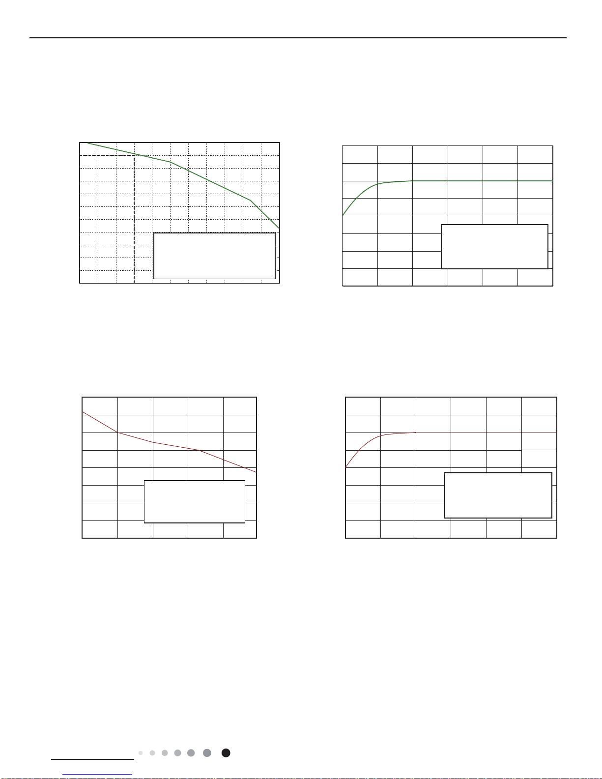
2.2 Operation Characteristic Curve
0
1
2
3
4
5
6
7
8
9
10
0 20 40 60 80 100 120
Condition
Indoor:DB 27°C WB19°C
Indoor air flow: Turbo
Pipe length:5m
Voltage:230V
Compressor Speed(rps)
0
1
2
3
4
5
6
7
8
0 20 40 60 80 100 120
Condition
Indoor:DB 20°C
Indoor air flow:Turbo
Pipe length:5m
Voltage:230V
Compressor Speed(rps)
Cooling
Heating
Current(A)
Current(A)
09K/12K
18K
0 10 20 30 40 50 60 70 90
80
0 10 20 30 40 50 60 70 80 90 100 120110
11
10
9
8
7
6
5
4
3
2
1
0
Compressor speed (rps)
)A(tnerruC
11
10
9
8
7
6
5
4
3
2
1
0
Compressor speed (rps)
)A(tnerruC
Cooling Heating
Conditions
Indoor: DB27°C/WB19°C
Indoor air flow: High
Pipe length: 5m
Conditions
Indoor: DB20°C/WB15°C
Indoor air flow: High
Pipe length: 5m
Cooling
Cooling
Heating
Heating
9
Technical Information
Service Manual
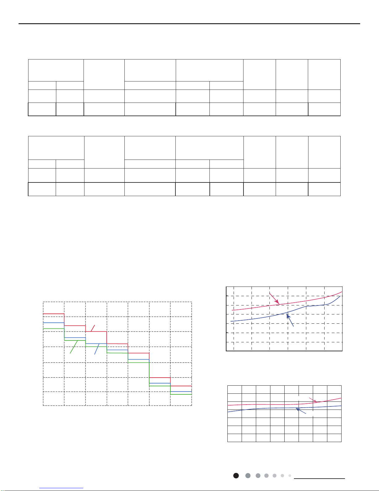
2.3 Capacity Variation Ratio According to Temperature
Cooling
Capacity ratio( %)
Heating
Outdoor temp.(°C) Outdoor temp.(°C)
32 34 36 38 40 42 44 46
5448 50 52
100
105
95
90
85
80
75
70
65
60
55
50
Conditions
Indoor:DB27°C/WB19°C
Indoor air flow:Super High
Pipe length: 5m
40
50
120
110
100
90
80
70
60
1070-8-20
Capacity ratio(%)
-30 -15
Conditions
Indoor:DB20°C
Indoor air flow:Super High
Pipe length: 5m
09K/12K
18K
Cooling
Cooling
Heating
Heating
Outdoor Temp.(°C)
Outdoor Temp.(°C)
Capacity ratio(%)
Capacity ratio(%)
29 34 39 44 49 54
60
70
80
90
100
110
120
50
40
40
50
120
110
100
90
80
70
60
1070-8-20
-30 -15
Conditions
Indoor: DB20°C/WB15°C
Indoor air flow: High
Pipe length: 5m
Conditions
Indoor: DB27°C/WB19°C
Indoor air flow: High
Pipe length: 5m
10
Technical Information
Service Manual
2.4 Cooling and Heating Data Sheet in Rated Frequency
Rated cooling
condition(°C) (DB/WB)
Model
Pressure of gas pipe
connecting indoor
and outdoor unit
Inlet and outlet pipe
temperature of heat
exchanger
Fan speed of
indoor unit
Fan speed of
outdoor unit
Compressor
revolution
(Hz)
Indoor Outdoor P (MPa) T1 (°C) T2 (°C)
27/19 35/24 09K/12K 0.85~1.0
in:8~11
out:11~14
in:50~80
out:37~43
Turbo Suprt High 58
27/19 35/24 18K 0.9~1.0
in:8~11
out:11~14
in:75~83
out:37~48
Super High High 73
Rated heating
condition(°C) (DB/WB)
Model
Pressure of gas pipe
connecting indoor
and outdoor unit
Inlet and outlet pipe
temperature of heat
exchanger
Fan speed of
indoor unit
Fan speed of
outdoor unit
Compressor
revolution
(Hz)
Indoor Outdoor P (MPa) T1 (°C) T2 (°C)
20/- 7/6 09K/12K 2.5~3.0
in:50~80
out:37~43
in:1~3
out:2~5
Turbo Suprt High 56
20/15 7/6 18K 2.2~2.4
in:75~83
out:37~45
in:1~3
out:2~6
Super High High 75
Instruction:
T1: Inlet and outlet pipe temperature of evaporator
T2: Inlet and outlet pipe temperature of condenser
P: Pressure at the side of big valve
Connection pipe length: 5 m.
Cooling:
Heating:
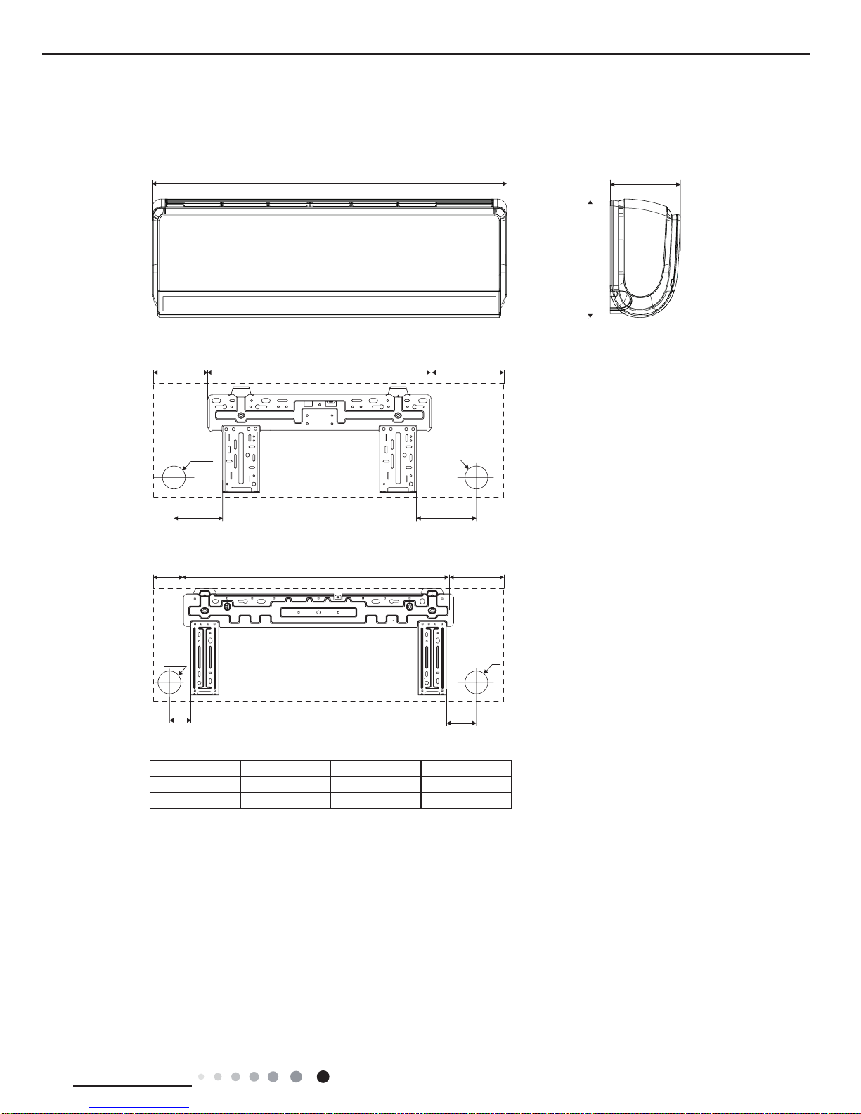
2.5 Noise Curve
45
50
35
40
30
20
15
25
Indoor side noise
Outdoor side noise
09K/12K
18K
Indoor fan motor rotating speed
SH MH M ML SLLH
40
42
44
46
48
50
52
54
20 4030 50 60 70 80
Compressor frequency(Hz)
Noise dB(A)
Noise dB(A)
Heating
Cooling
09K
12K
18K
46
48
50
52
54
56
58
60
20 30 40 50 60 70 80 90 100
Compressor frequency(Hz)
Noise dB(A)
Heating
Cooling
11
Technical Information
Service Manual
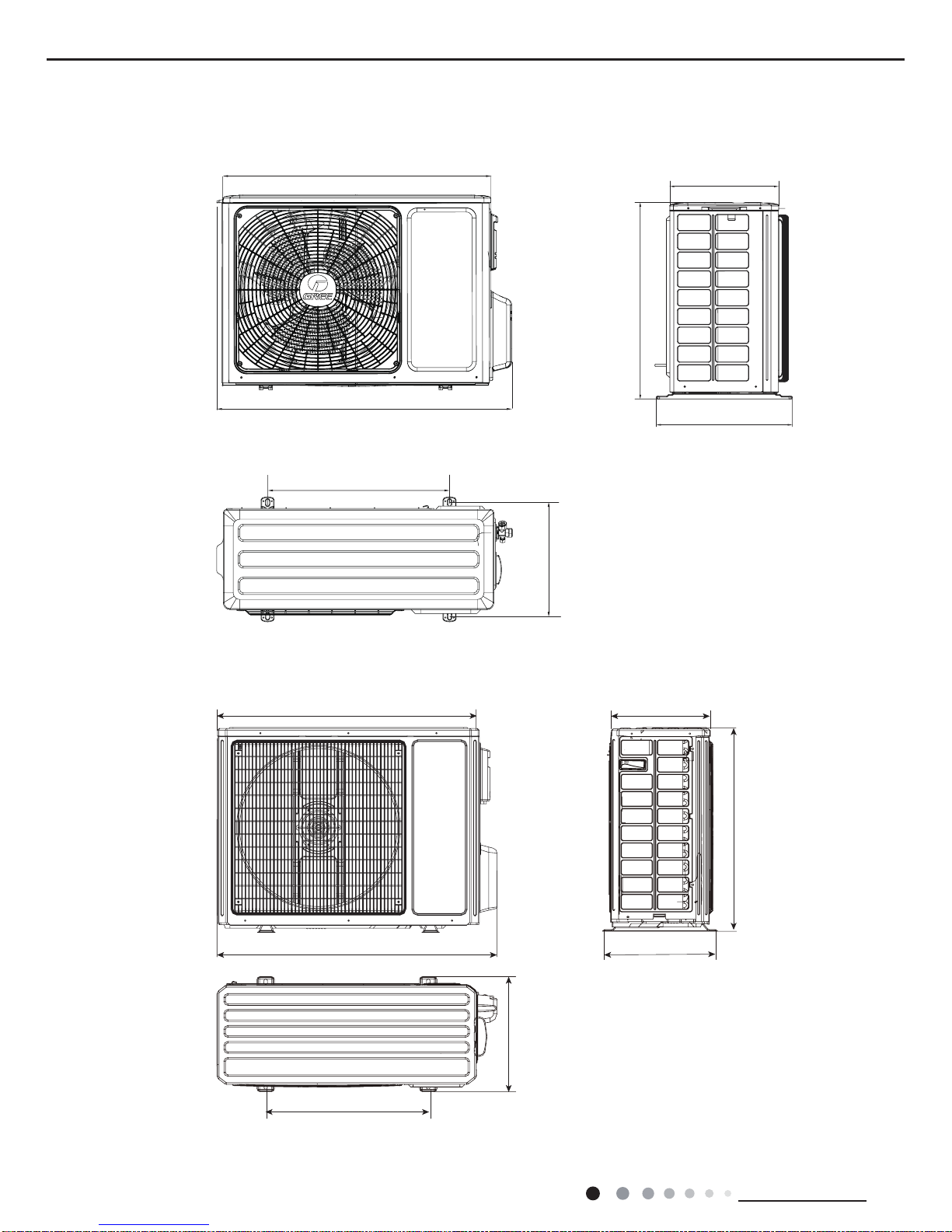
3. Outline Dimension Diagram
3.1 Indoor Unit
125 148
Φ55
Φ55
49.5
80
Φ55
Φ55
W
136
90 684 186
542 179
D
H
Unit:mm
Model W H D
12K 860 305 170
18K 960 320 205
09K/12K
18K
12
Technical Information
Service Manual
3.2 Outdoor Unit
899
810
550
343
303
596
378
Unit:mm
Unit:mm
965
892
700
396
560
341
396
18K
09K/12K
13
Technical Information
Service Manual
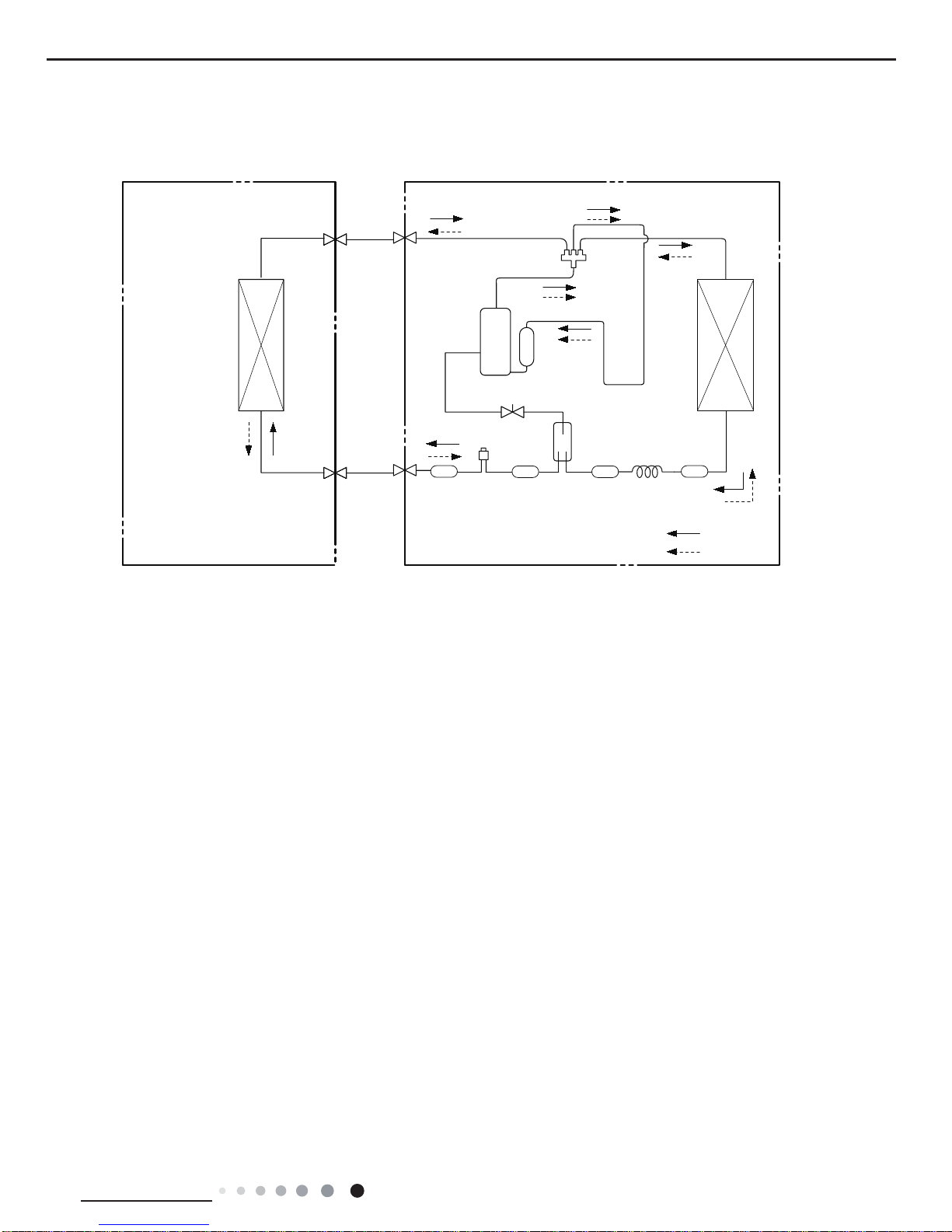
4. Refrigerant System Diagram
Connection pipe specication:
Liquid : 1/4" (6mm) Gas : 1/2" (16mm)
6HUYLFH0DQXDO
5HIULJHUDQW6\VWHP'LDJUDP
INDOOR UNIT OUTDOOR UNIT
HEAT
EXCHANGE
(EVAPORATOR)
HEAT
EXCHANGE
(CONDENSER)
COMPRESSOR
GAS SIDE
3-WAY VALVE
LIQUID SIDE
2-WAY VALVE
COOLING
HEATING
Accumlator
Discharge
Suction
4-Way valve
Electron
Strainer
Strainer
expansion
valve
Strainer
Capillary
D
Strainer
Intercooler

14
Technical Information
Service Manual
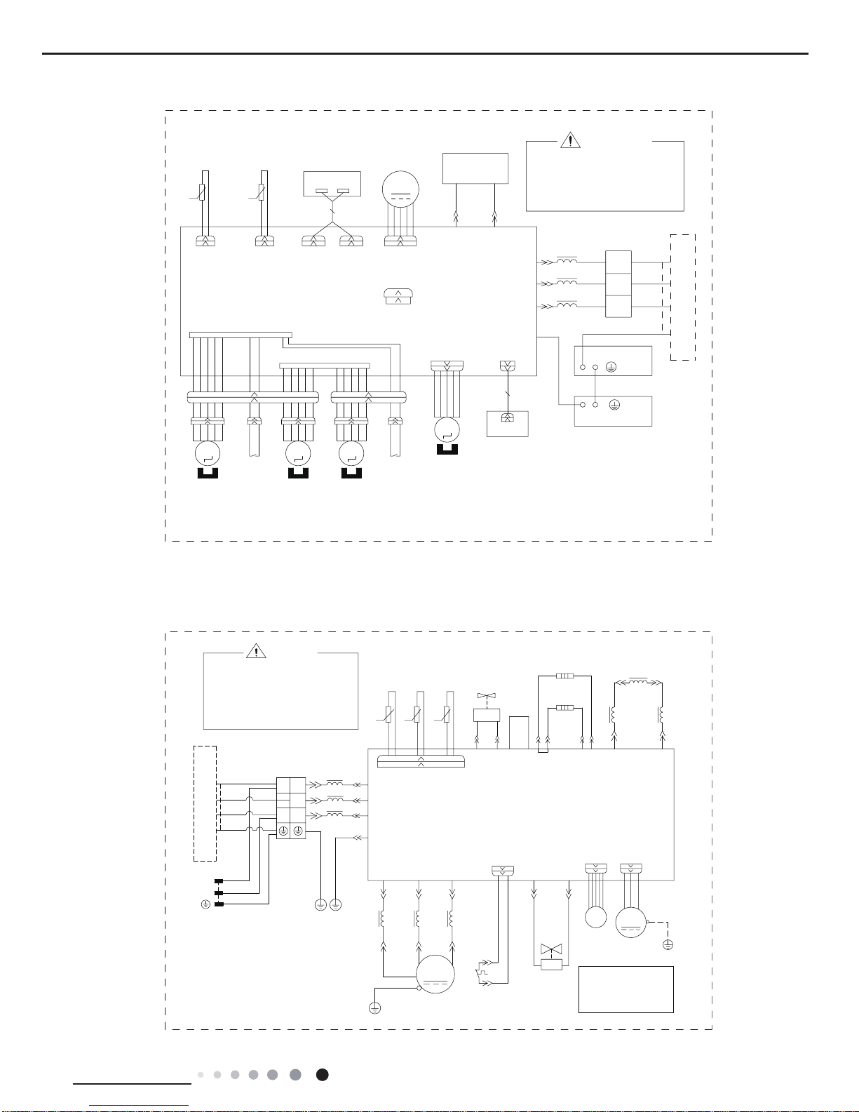
5. Electrical Part
5.1 Wiring Diagram
● Indoor Unit
●Instruction
Symbol Symbol Color Symbol Symbol Color Symbol Name
WH White GN Green CAP Jumper cap
YE Yellow BN Brown COMP Compressor
RD Red BU Blue Grounding wire
YEGN Yellow/Green BK Black / /
VT Violet OG Orange / /
Note: Jumper cap is used to determine fan speed and the swing angle of horizontal lover for this model.
GWH09UB-K3DNA4F/I(Cold Plasma), GWH12UB-K3DNA4F/I(Cold Plasma)
6:,1*/5
&$%/(
&11(&7,1*
+($/7+1
+($/7+/
5'
*(1(5$725
&2/'
3/$60$
%8
67(33,1*
02725
/()75,*+7
0
0
5,*+7
5,*+7
,1*+,1*
6:,7&+
02725
0
/()7
02725
&1
02725
/()7
,1*+,1*
6:,7&+
&1
'&02725
&1
'(7(&7,216
%2$5'
&203&
$3
78%(
0
$3
1
287'22581,7
<(*1
<(*1
3(
(9$325$725
%1
%.
%8
;7
%8
%.
%1
%/2&.
7(50,1$/
1
$&/
&20287
&$3
-803
$30$,1%2$5'
',63
',63
)$1
02725
',63/$<%2$5'
67(33,1*
83'2:1
0
57
57
6(1625
5220
6(1625
5220
7(03
78%(
7(03
RIHOHFWULFVKRFN
3OHDVHGRQWWRXFKDQ\
WHUPLQDOZKHQWKHPDFKLQHLV
UXQQLQJVWRSSLQJRUKDVEHHQ
SRZHUHGRIIIRUOHVVWKDQ
PLQXWHVWRSUHYHQWWKHULVN
:$51,1*
15
Technical Information
Service Manual
GWH18UC-K3DNA4F/I(Cold Plasma)
+($/7+1+($/7+/
%85'
&2/'3/$60$
*(1(5$725
6:,1*/5
%8
%.
%1
<(*1
(9$325$725
3(
3(
($57+3/$7(
1
287'22581,7
',63/$<%2$5'
57
&1
&1
,1&+,1*
5,*+7
5,*+7
/()7
<(*1
6:,7&+
,1&+,1*
0272502725
/()7
02725
67(33,1*
6(1625
52207(03
6(1625
78%(7(03
'(7(&7,216
%2$5'
67(33,1*
/()75,*+7
6:,7&+
02725
83'2:1
)$102725
$3&1
&203&
'&02725
5220
57
78%(
$3
-803
&$3
',63',63
%1
%8
%.
$&/
&20287
$30$,1%2$5'
1
%/2&.
7(50,1$/
;7
5,1*
0$*1(7,&
/
/
/
<(*1
3(
3OHDVHGRQWWRXFKDQ\HOHFWURQLF
FRPSRQHQWRUWHUPLQDOZKHQWKH
PDFKLQHLVUXQQLQJVWRSSLQJRUKDV
EHHQSRZHUHGRIIIRUOHVVWKDQ
PLQXWHVWRSUHYHQWHOHFWULFVKRFN
:$51,1*
0
000
0
● Outdoor Unit
GWH09UB-K3DNA4F/O, GWH12UB-K3DNA4F/O
32:(5
RIHOHFWULFVKRFN
3OHDVHGRQWWRXFKDQ\
WHUPLQDOZKHQWKHPDFKLQHLV
UXQQLQJVWRSSLQJRUKDVEHHQ
SRZHUHGRIIIRUOHVVWKDQ
PLQXWHVWRSUHYHQWWKHULVN
:$51,1*
<9
/
1
3(
3(3(
$30DLQ%RDUG
&1
&1
2)$19$
$&/
+($7/
+($71
+($71
/; /;
1
&208
$&/
(
&2038 &2039 &203:
29&&203
:$< $&/
&1 2)$1
28778%(
7(03
6(1625
2875220
7(03
6(1625
(;+$867
7(03
6(1625
57
57
57
. . .
:$<
9$/9(
%$1'+($7(5
%27721
%$1'+($7(5
&2035(6625
5($&725
0$*1(7,&
5,1*
/ /
3(
)$1
02725
(/(&7521,&
(;3$16,21
9$/9(
0
(.9
6$7
&203
&203
3(
3(
:$<
9$/9(
29(5/2$5'
3527(&725
<9
0$*1(7,&
5,1*
7(50,1$/
%/2&.
0$*1(7,&
5,1*
2* :+
<(*1
9797
5'5'
5'<(%8
///
<(*1
<(*1
<(*1
%1
%8
%.
/
/
/
%8
%.
%1
<(*1
;7
127(
0RWRU
DSSOLHVWRWKH
LURQVKHOOPRWRU
JURXQGRQO\
1 1
:,5(
%8
N(1)
,1'22581,7
/
1
%8
%1
<(*1
16
Technical Information
Service Manual
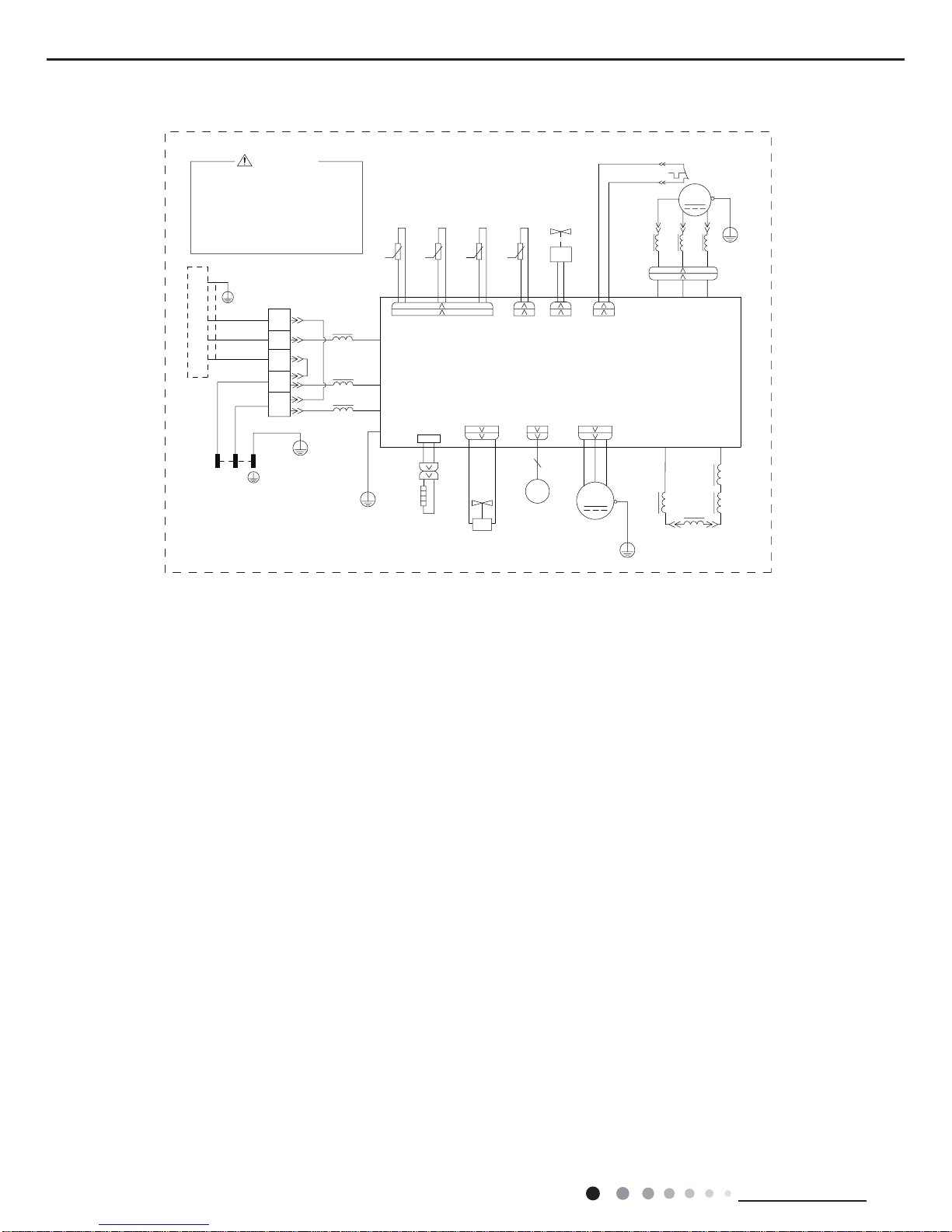
These wiring diagrams are subject to change without notice; please refer to the one supplied with the unit.
GWH18UC-K3DNA4F/O
3OHDVHGRQWWRXFKDQ\
WHUPLQDOZKHQWKHYROWDJH
RIWHUPLQDO3'&DQG
1'&DW$3LVKLJKHU
WKDQ9WRSUHYHQWWKH
ULVNRIHOHFWULFVKRFN
&20B,11(5
<9
:$<9$/9(
/
:
9
8
5($&725
2*:+
9$/9(
(;3$16,21
(/(&7521,&
)$
(.9
35,17('&,5&8,7%2$5'
)$1
3(
<(*1
7(036(1625
(;+$867
7(036(1625
2875220
28778%(
7(036(1625
%.:+
%8 <(
&203
;
&203
6$7
:+
29&B&203
2)$1
3(
5'
0
575757
3(
3(
5'%8 <(
8%8 9<( :5'
<(*1
7B6(1625
29(5/2$'3527(&725
:$51,1*
/
0$*1(7,&
5,1*
//
:$<
<9
9
9$/9(
97 97
/
/
,1'&,1'&
$&B/
11
&1
:+
$3
.
.
.
/
%1
/
/
0$*1(7,&
3(
7(50,1$/
%/2&.
<(*1
%8
%1
%8
%1
%.
5,1*
/
,1'22581,7
;7
%8
%.
%1
1
/
1
3(
%8
<(*1
32:(5
/ 1
3(
<(*1
3(
+($7
(+
5'
%27720
+($7(5
%$1'
5'
02725
28778%(
7(036(1625
57
:+
0$18$/
17
Technical Information
Service Manual
1
3
4 5 7 8 9 10
11
12
13
15
2
6
14
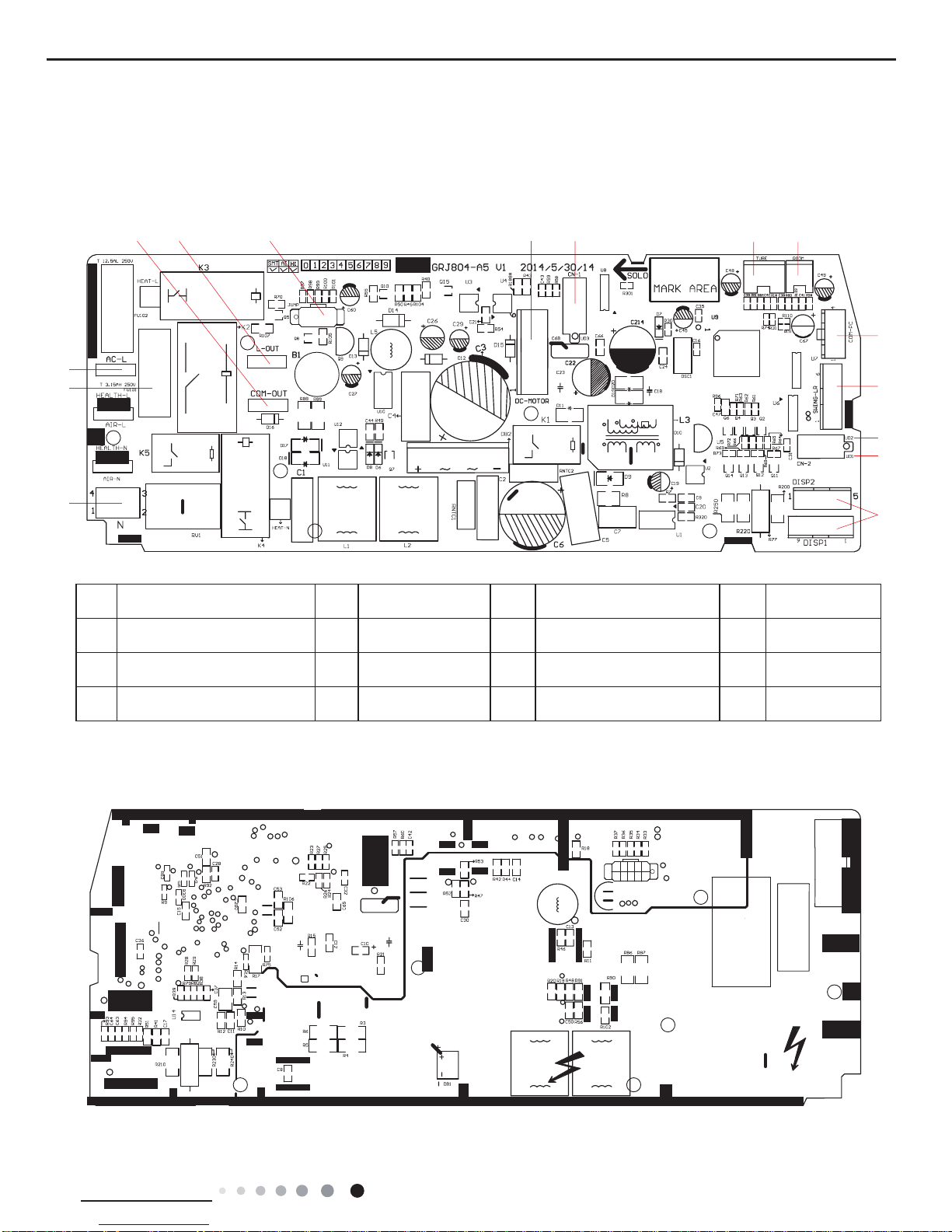
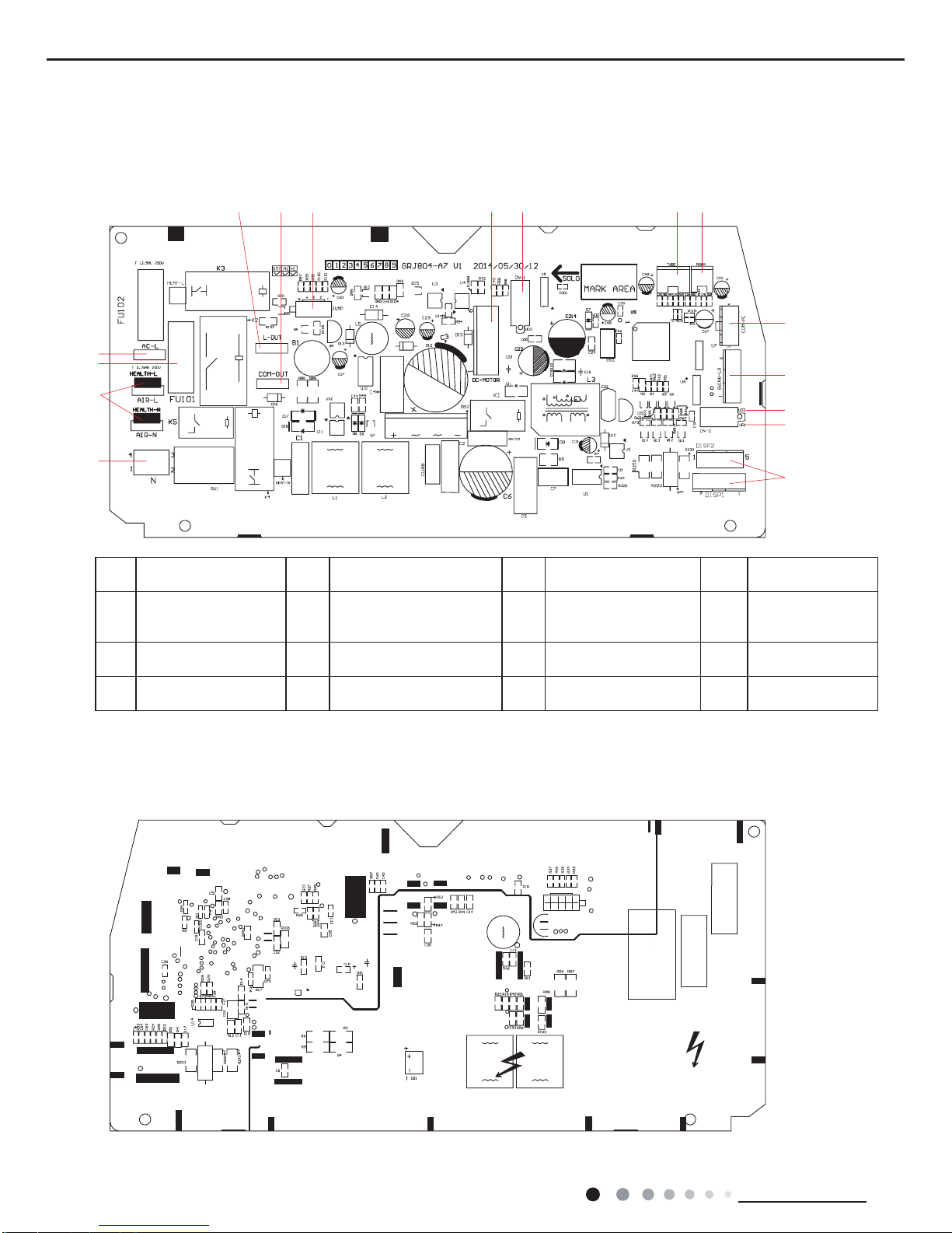
5.2 PCB Printed Diagram
● Top view
Indoor Unit
● Bottom view
1 Interface of neutral wire 5
Interface of live wire
for outdoor unit
9 Tube temperature sensor 13 Up&down swing 2
2 Interface of fuse 6
Interface of jumper
cap
10 Ambient temperature sensor 14 Up&down swing 1
3 Interface of live wire 7 Indoor fan motor 11
Communication interface for
radio-frequency, WIFI
15 Display interface
4
Interface of communication wire
for neutral wire and live wire
8 Up&down swing 3 12 Interface of left&right swing / /
09K/12K
18
Technical Information
Service Manual
8 95 6 7
1
2
3
4
10 11
12
13
16
14
15
● Top view
● Bottom view
1 Interface of neutral wire 5
Interface of live wire for
outdoor unit
9 Up&down swing 3 13
Interface of left&right
swing
2 Health interface 6
Interface of communication
wire for neutral wire and live
wire
10 Tube temperature sensor 14 Up&down swing 2
3 Interface of fuse 7 Interface of jumper cap 11
Ambient temperature
sensor
15 Up&down swing 1
4 Interface of live wire 8 Interface of DC motor 12
Communication interface
for radio-frequency, WIFI
16 Display interface
18K
19
Technical Information
Service Manual
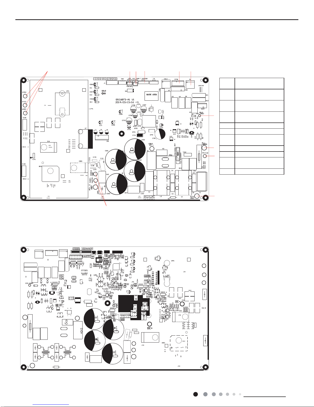
● Top view
● Bottom view
Outdoor Unit
09K/12K
2
1
3
4
5
6
8
7
9
10
11
12
13
14 15
20
Technical Information
Service Manual
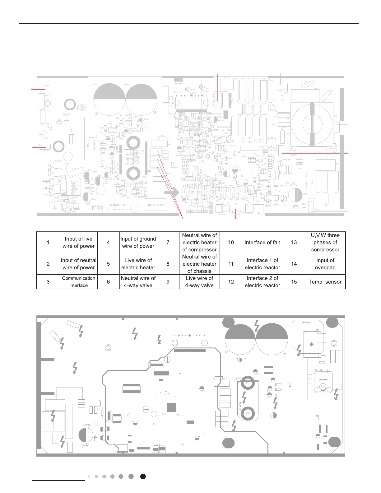
1 2 3 4 5 6
7
8
9
10
11
1
Terminal of compressor
wire
2
Terminal of low pressure
protection
3
Terminal of compressor
overload protection
4
Terminal of outdoor
temperature sensor
5 Terminal of outdoor fan
6 Terminal of 4-way valve
7
Communication wire
with indoor unit
8 Power supply live wire
9 Earthing wire
10
Power supply neutral
wire
11 PFC induction wire
● Top view
● Bottom view
18K
21
Technical Information
Service Manual
6. Function and Control
6.1 Remote Controller Introduction
Specialties note
Note:
● Please done the following operation within 6.56ft from the unit. Matching is not needed anymore once it is done.
● During matching, please keep the remote controller and air conditioner under standby status.
● When the signal of remote controller can’t be received, please match the remote controller with the unit again.
Matching of remote controlle
When the unit is under standby status, please get close to the air conditioner within 6.56ft and then hold on pressing
button for 3s. The remote controller and air conditioner will enter matching automatically. If matching is done, the unit will give
out three sounds; if matching is failed, please get closer to the unit and arrange matching again.
Matching instructions
This model adopts RF remote control. The remote controller shall be matched with the air
conditioner before operation, otherwise the remote control will be invalid. Before operation, please
read the instructions in this page carefully and then do the corresponding matching operation.
Humidify/Health
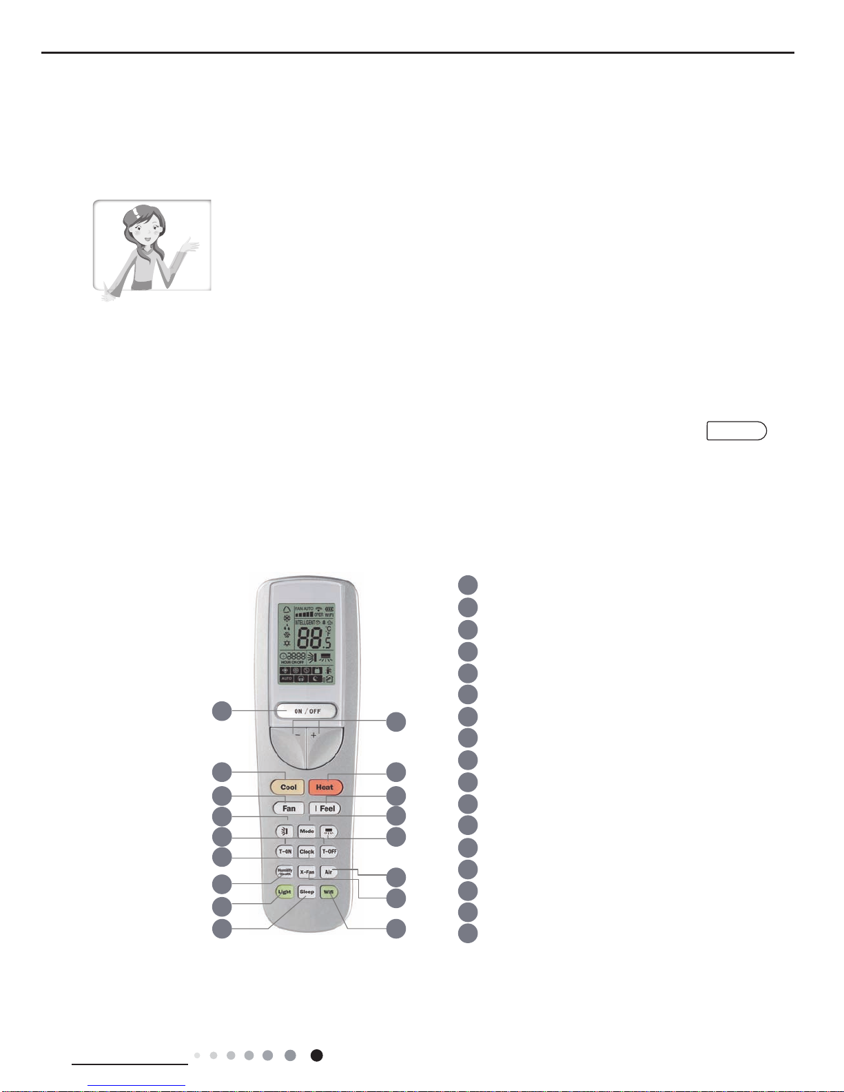
Buttons on Remote Controller
3
2
5 6
10
11
12
15
9
17
14
13
16
8
7
4
1
1 ON/OFF button
2
+/- button
3
Cool button
4
Heat button
6 I FEEL button
7
up down swing button
9
Left right swing button
14
X-fan button
15
Sleep button
Light button
16
17
WIFI button
11
Clock button
12
13
Humidity button/Health button
Air button
10
T-ON/T-OFF button
8
Mode button
5
Fan button
22
Technical Information
Service Manual
2. +/- button
Press "+" or " - " button once increase or decrease set temperature 0.5 °C. Holding "+" or " - " button, 2s later, set temperature on remote
controller will change quickly.On releasing button after setting is nished, temperature indicator on indoor unit will change accordingly.
(Temperature can’t be adjusted under auto mode)
When setting TIMER , press "+" or " - " button to adjust time.
3. Cool button
Press this button, unit will operate in cool mode.
4. Heat button
Press this button, unit will operate in heat mode.
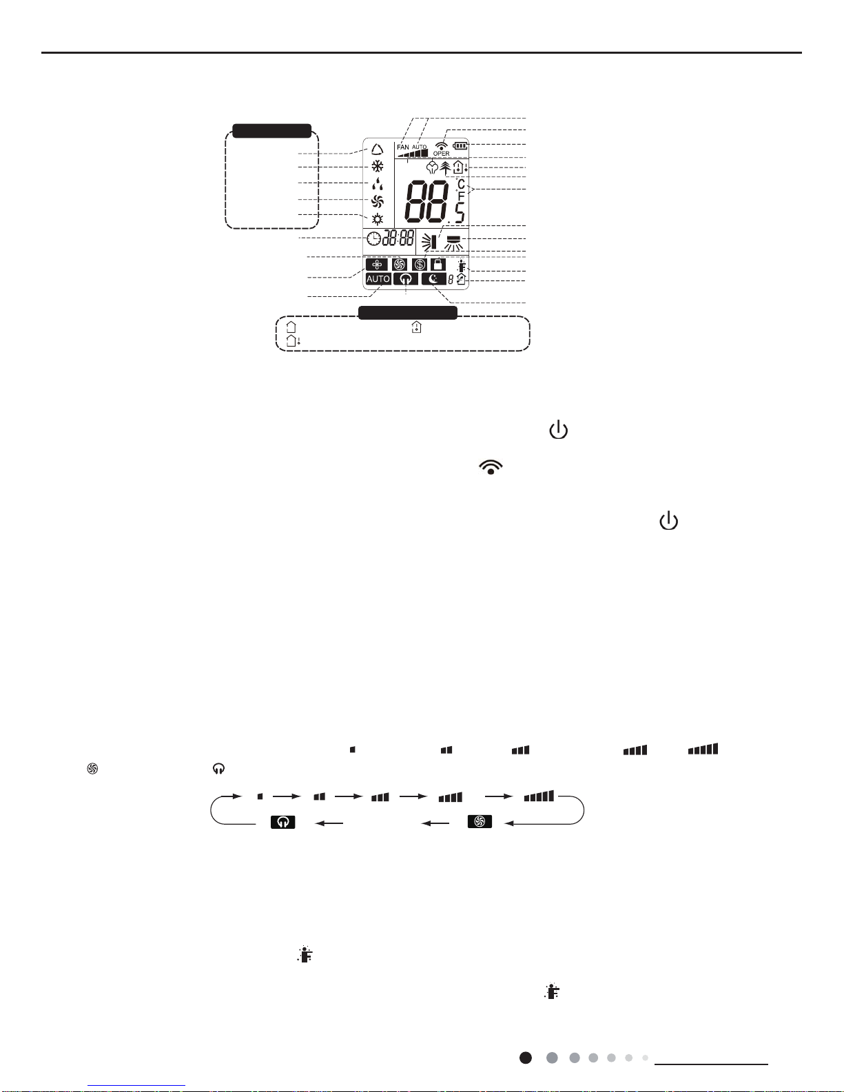
5. FAN button
Pressing this button can set fan speed circularly as: low( ), low medium( ),medium( ), medium high( ),high( ),
super( ),auto(AUTO),quiet( ).
Note:
● Turbo function is not available under dry and auto mode.
● Automatically operate slient speed when starting sleep fuction.
● The unit operates at low speed under dry and auto dry mode. The speed can't be adjusted.
● Under AUTO speed, air conditioner will select proper fan speed automatically according to ambient temperature.
6. I FEEL button
Press this button to start I FEEL function and " " will be displayed on the remote controller. After this function is set, the remote
controller will send the detected ambient temperature to the controller and the unit will automatically adjust the indoor temperature
according to the detected temperature. Press this button again to close I FEEL function and " " will disappear.
● Please put the remote controller near user when this function is set. Do not put the remote controller near the object of high temperature or
low temperature in order to avoid detecting inaccurate ambient temperature.
Auto
Introduction for Icons on Display Screen
battery power
Send signal
8ć heating function
I feel function
Set fan speed
Temp. display type
:Set temp.
:Outdoor ambient temp.
:Indoor ambient temp.
Heat mode
Fan mode
Dry mode
Cool mode
Auto mode
Operation mode
humidity functions
Temp.display type
Healthy mode
Set temperature
INTELLIGENT
HOUR ON OFF
WIFI
Up & down swing
Left & right swing
child lock
Replacing air
Quiet mode
Auto quiet mode
X-FAN function
Turbo fan speed
Sleep mode
Set time
Introduction for Buttons on Remote Controller
Note:
● After putting through the power, the air conditioner will give out a sound. Operation indictor " " is ON (red indicator). After that, you
can operate the air conditioner by using remote controller.
● Under on status, pressing the button on the remote controller, the signal icon " " on the display of remote controller will blink once
and the air conditioner will give out a “de” sound, which means the signal has been sent to the air conditioner.
1. ON/OFF Button
Press this button can turn on or turn off the air conditioner. After turning on the air conditioner, operation indicator " "on indoor unit’s
display is ON (green indicator. The colour is different for different models), and indoor unit will give out a sound.
23
Technical Information
Service Manual
7. button
Under simple swing mode, press this button can turn on (display " " icon ) or turn off ( not display " " icon) left&right swing
function.
Under OFF status, press "+" button and " " button simultaneously can switch between simple swing mode and xed swing mode.
During switching time, “ ” icon on remote controller will ash twice.
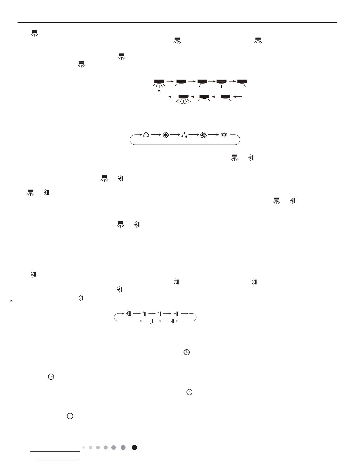
Under xed-angle swing mode, press this button and the left and right swing status will change in the sequence as below:
8. MODE button
Press this button to select your required operation mode.
When selecting auto mode, air conditioner will operate automatically according to ambient temperature. Set temperature can’t be
adjusted and will not be displayed as well. Press "FAN" button can adjust fan speed. Press " " / " " button can adjust fan blowing
angle.
After selecting cool mode, air conditioner will operate under cool mode. Press "+" or "-" button to adjust set temperature. Press "FAN"
button to adjust fan speed.Press " " / " " button to adjust fan blowing angle.
When selecting dry mode, the air conditioner operates at low speed under dry mode. Under dry mode, fan speed can’t be adjusted. Press
" " / " " button to adjust fan blowing angle.
When selecting fan mode, the air conditioner will only blow fan,Press "FAN" button to adjust fan speed. Press " " / " " button to
adjust fan blowing angle.
When selecting heating mode, the air conditioner operates under heat mode. Press "+" or "- " button to adjust set temperature. Press
"FAN" button to adjust fan speed. Press " " / " " button to adjust fan blowing angle. (Cooling only unit won’t receive heating mode
signal. If setting heat mode with remote controller, press ON/OFF button can’t start up the unit).
no display
(stops at current position)
AUTO COOL FANDRY HEAT
Note:
● For preventing cold air, after starting up heating mode, indoor unit will delay 1~5 minutes to blow air (actual delay time is depend on
indoor ambient temperature).
● Set temperature range from remote controller: 16~30°C (61-86°F);
9. button
Under simple swing mode, press this button can turn on ( display " " icon) or turn off ( not display " " icon) up&down swing function.
Under OFF status, press "+" button and " " button simultaneously can switch between simple swing mode and xed swing mode.
During switching time, “ ” icon on remote controller will ash twice.
Under xed swing mode, press this button and up and down swing status will change in the sequence as below:
10. T-ON/T-OFF button
T-ON button
“T-ON” button can set the time for timer on. After pressing this button, " " icon disappears and the word “ON" on remote controller
blinks. Press “+” or “-”button to adjust T-ON setting. After each pressing “+” or “-”button, T-ON setting will increase or decrease 1min. Hold
“+” or “-”button, 2s later, the time will change quickly until reaching your required time. Press“T-ON”to conrm it. The word “ON” will stop
blinking. " " icon resumes displaying.Cancel TIMER ON: Under the condition that T-ON is started up, press “T-ON” button to cancel it.
T-OFF button
“T-OFF” button can set the time for timer off. After pressing this button, " " icon disappears and the word "OFF" on remote controller
blinks. Press "+" or "-" button to adjust T-OFF setting. After each pressing "+" or "-" button, T-OFF setting will increase or decrease 1min.
Hold "+" or "-" button, 2s later, the time will change until reaching your required time. Press“T-OFF”to conrm it. The word “ON”will "OFF"
will stop blinking. " " icon resumes displaying. Cancel T-OFF.Under the condition that T-OFF is started up, press “T-OFF” button to
cancel it.
no display
(horizontal louvers stops
at current position)
24
Technical Information
Service Manual
Note:
● Under on and off status, you can set T-OFF or T-ON simultaneously.
● Before setting T-ON or T-OFF, please adjust the clock time.
● After starting up T-ON or T-OFF, set the constant circulating valid. After that, air conditioner will be turned on or turned off according to
setting time. ON/OFF button has no effect on setting. If you don’t need this function, please use remote controller to cancel it.
11. CLOCK button
Press this button to set clock time. " " icon on remote controller will blink. Press "+" or "-" button within 5s to set clock time. Each
pressing of "+" or "-" button, clock time will increase or decrease 1 minute. Hold "+" or "-" button, 2s later, time will change quickly.
Release this button when reaching your required time. Press “CLOCK”button to conrm the time. " " icon stops blinking.
Note:
● Clock time adopts 24-hour mode.
● The interval between two operations can’t exceeds 5s. Otherwise, remote controller will quit setting status. Operation for TIMER ON/
TIMER OFF is the same.
12. Humdity/health button
Press this button to select your required operation mode.
Note:there is no this function for this unit. If press this button,the main unit will click, but it also runs under original status.
13. X-FAN button
Pressing this button in COOL or DRY mode, the icon " " is displayed and the indoor fan will continue operation for 2 minutes in order
to dry the indoor unit even though you have turned off the unit. After energization, X-FAN OFF is defaulted. X-FAN is not available in
AUTO, FAN or HEAT mode.
This function indicates that moisture on evaporator of indoor unit will be blowed after the unit is stopped to avoid mould.
● Having set X-FAN function on: After turning off the unit by pressing ON/OFF button indoor fan will continue running for about 2 min. at
low speed. In this period, press X-FAN button to stop indoor fan directly.
● Having set X-FAN function off: After turning off the unit by pressing ON/OFF button, the complete unit will be off directly.
INTELLIGENT
INTELLIGENT
cancel
14. Air button
Press this button to select your required operation mode.
Note:there is no this function for this unit. If press this button,the main unit will click, but it also runs under original status.
15. LIGHT button
Pressing this button to turn off display light on indoor unit. Press this button again to turn on display light.
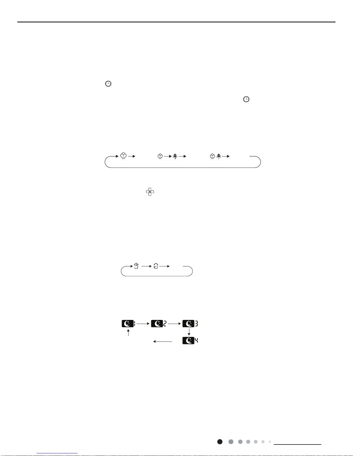
16. SLEEP button
Pressing this button can select Sleep 1, Sleep 2,Sleep 3, Sleep 4 or cancel Sleep circularly as below:
In Sleep 1 and Sleep 2, the air conditioner will run according to a group of presetting temperature curves.
●Sleep 3 - the sleep curve setting under DIY Sleep mode:
(1) Under Sleep 3 mode, long press "AIR" button, the remote controller will enter the setting of personalized sleep. In this case, the timer
zone of remote controller will display "1 hr" and the set temperature zone "88" will display the corresponding temperature of the last set
sleep curve and blink (The rst entering will display according to the initial curve setting value of manufacturer);
(2) Press "+" and "-" button to adjust the corresponding temperature. After adjusting, press "AIR" button to conrm it;
(3) At this time, the timer time on the remote controller will increase automatically by 1hr (that is "2 hr" or "3 hr" … or "8 hr"). The set
temperature zone "88" will display the corresponding temperature of the last set sleep curve and blink;
(4)Repeat step(2) and step (3) until 8-hour temperature setting is nished, then the sleep curve is set successfully. After that, remote
controller will resume displaying the original timer time and temperature zone will resume displaying the original set temperature.
cancel
cancel
25
Technical Information
Service Manual
●Sleep 3 - the sleep curve inquiry under DIY Sleep mode:
User can inquire the set sleep curve according to the setting method of sleep curve. Enter the setting of personalized sleep but do not
change the temperature. Then press "AIR" button to conrm the setting.
Note: In the above setting or inquiry procedure, if there is no button pressing within 10s, remote controller will automatically exit the sleep
curve setting and resume the original display. If ON/OFF, MODE, TIMER, HUMIDIFY, SLEEP, COOLING or HEATING button is pressed
during the setting or inquiry procedure, remote controller will also exit the sleep curve setting.
●Sleep 4 is Siesta mode. The set temperature will change automatically according to the features of siesta.
●Sleep function will be disabled if the air condition is restarted after power failure;when sleep function is turned on, quite fan speed will be
also turned on.
●Sleep function can not be set in AUTO mode.
17. Wi button
Press this button 3s can set wi function on or OFF.
At OFF status,press mode button and wi button,can reset wi mode parameter and open wi function.
About X-FAN function
This function indicates that moisture on evaporator of indoor unit will be blowed after the unit is stopped to avoid mould.
1. Having set X-FAN function on: After turning off the unit by pressing ON/OFF button indoor fan will continue running for about 2 min. at
low speed. In this period, press X-FAN button to stop indoor fan directly.
2. Having set X-FAN function off: After turning off the unit by pressing ON/OFF button, the complete unit will be off directly.
About AUTO RUN
When AUTO RUN mode is selected, the setting temperature will not be displayed on the LCD, the unit will be in accordance with the room
temp. automatically to select the suitable running method and to make ambient comfortable.
About lock
Press + and - buttons simultaneously to lock or unlock the keyboard. If the remote controller is locked, the icon will be displayed on it,
in which case, press any button, the mark will icker for three times. If the keyboard is unlocked, the mark will disappear.
About switch between Fahrenheit and Centigrade
Under status of unit off, press MODE and - buttons simultaneously to switch °C and °F.
Note:
● During operation, point the remote control signal sender at the receiving window on indoor unit.
● The distance between signal sender and receiving window should be no more than 26.25ft , and
there should be no obstacles between them.
● Signal may be interfered easily in the room where there is uorescent lamp or wireless telephone;
remote controller should be close to indoor unit during operation.
● Replace new batteries of the same model when replacement is required.
● When you don’t use remote controller for a long time, please take out the batteries.
● If the display on remote controller is fuzzy or there’s no display, please replace batteries.
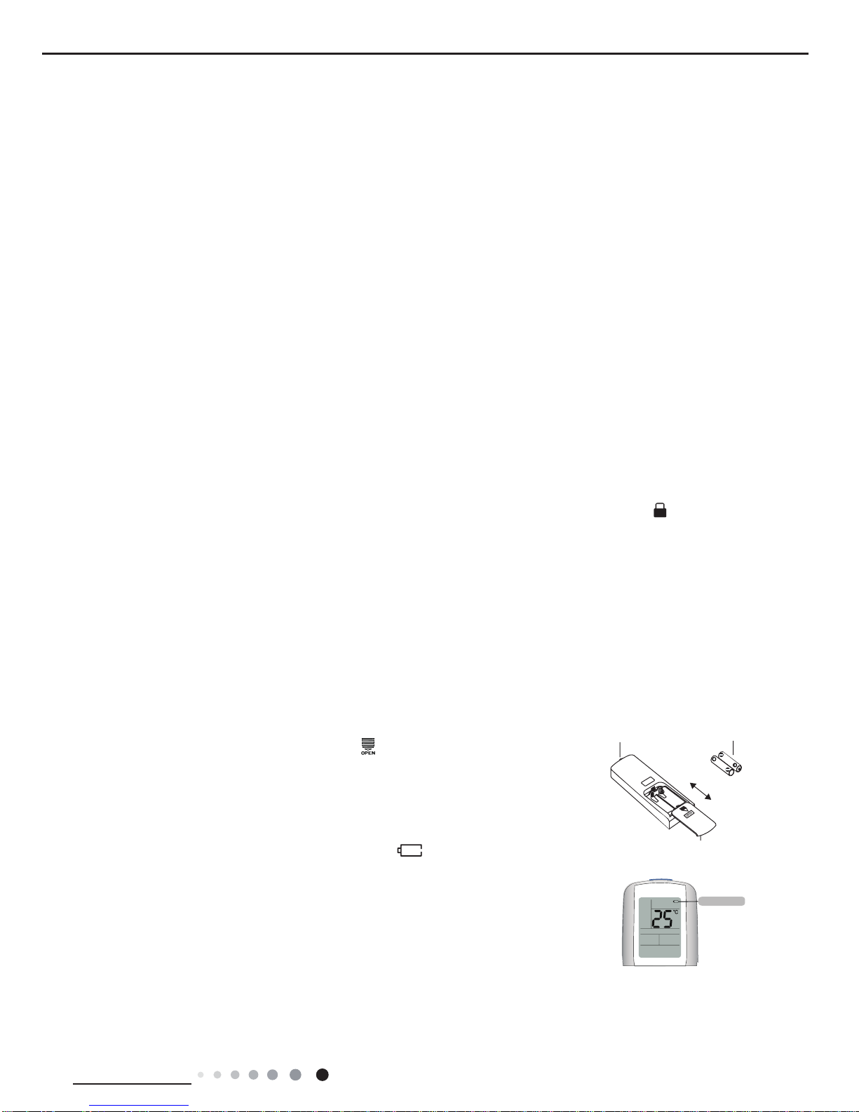
1.Press the back side of remote controller marked with“ ”as shown in the g,
and then push out the cover of battery box along the arrow direction.
2.Replace two 7# (AAA 1.5V) dry batteries, and make sure the position of "+" polar
and "-" polar are correct.
3. Reinstall the cover of battery box.
1. After putting through the power, press "ON/OFF" button on remote controller to turn on the air conditioner.
2. Press "MODE" button to select your required mode: AUTO, COOL, DRY, FAN,HEAT.
3. Press "+" or " - " button to set your required temperature. (Temperature can’t be adjusted under auto mode).
4. Press "FAN" button to set your required fan speed: auto, low, medium and high speed.
5. Press "SWING" button to select fan blowing angle.
Replacement of batteries in remote controller
Operation guide
signal sender battery
Cover of battery box
remove
reinstall
battery level
Battery level will be displayed on the remote controller.When " " is ickering,
please replace the batteries, otherwise, remote controller can’t operate normally.
26
Technical Information
Service Manual
6.2 Operation of Smart Control (Smart Phone, Tablet PC)
Special Function
How to operate AC or auxiliary device with smart phone or tablet PC after matching:
First of all: before using smart connection function, please make sure your smart phone or tablet computer uses the standard
Android or iOS operating system.
Please refer to the application program for the specic version. This air conditioner can connect 4 smart phones or tablet computers
in maximum.
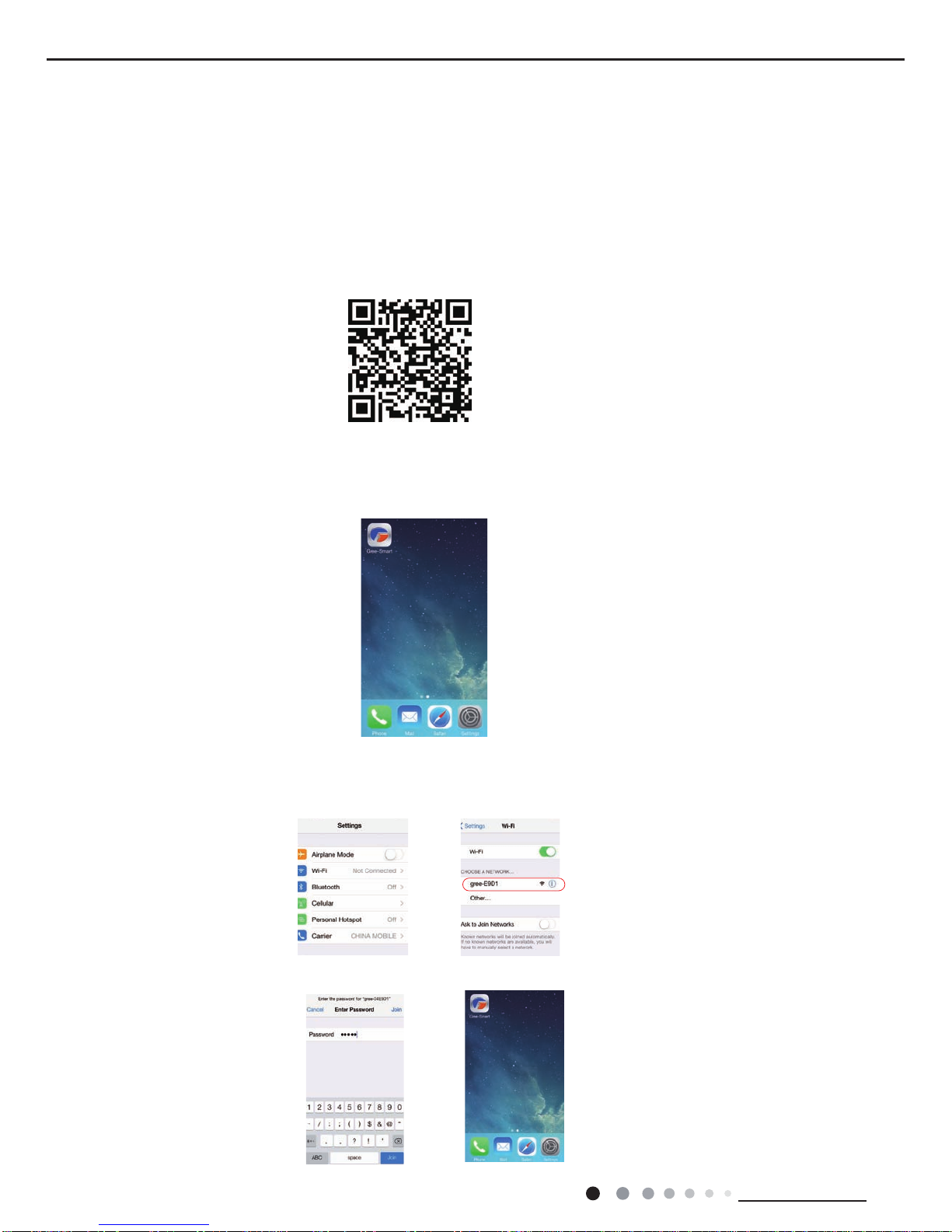
1. Install Gree-Smart on your smart phone/ tablet PC
Method 1: Enter Gree ofcial website http://www.gree.com/english/. Search Gree-Smart Application in "Download Center".
Method 2: Scan the QR code and download the application directly (If your device is not compatible, please download the application
in other ways.)
Method 3: Users of iOS system can search the application “Gree-Smart” through Apple’s App Store. After it is successfully installed,
you will see the picture below.
Following is the example using iphone4s. (The interface of the application may vary as it is upgraded or used in different operating
systems. Please refer to actual application.)
2. Turn on the AC WiFi:
Turn the AC on. First, make sure the remote controller is matched. Then, long-press “WiFi” button on the remote controller for at
least 3 seconds. If WiFi icon is shown, it means the WiFi function is turned on.
3. Enter the WiFi setting of your phone and search for the wireless network named gree-xxxxxxxx. Take gree-E9D1 as an example.
Connect the network.
4. Input the original password 12345 to connect the network.
27
Technical Information
Service Manual
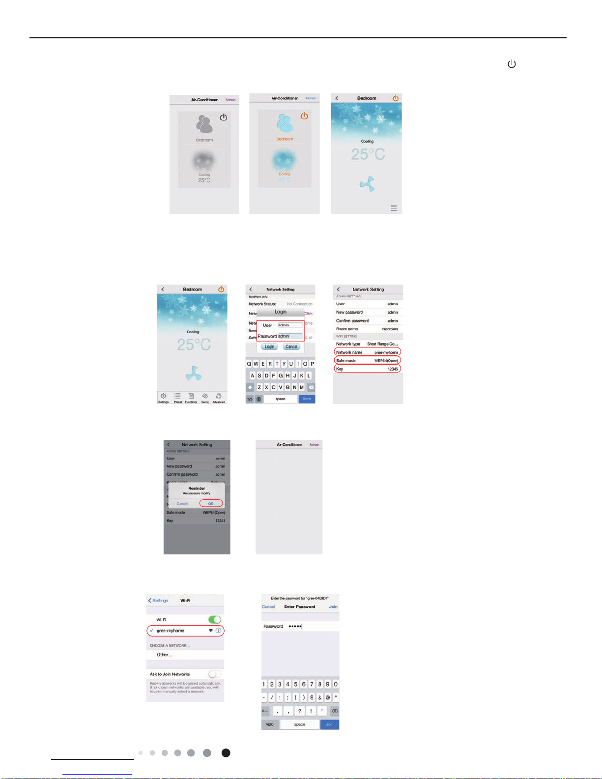
5.Open the application software and click “Refresh”, and then system will link with the air conditioner automatically. Click “ ” to turn
on the control function, and then clock any position on the interface and then software will switch to the remote control interface.
Attention: please change the name and key of the network during the rst setting!
6. Left-slide the bottom function bar to “Settings” and click it to enter into internet setting interface. Click “Network Setting”, and input
user name and password (the defaulted user name and password is admin) in the “Login” dialog box to enter into “Network Setting”
to modify network name (e.g. gree-my home) and password (refer to the attachment: safe mode and password instruction).
7. After modifying name and password, click it to return and there will be a prompt box, and then clock “OK” to nish the modication.
Meanwhile, the software will turn back to interface of “Air-Conditioner” and the AC list will be gone.
8. Exit the application and enter your phone’s WiFi Setting. Then you will see the network you just named “gree-my home". Click it
and input the password set in step 6 to join the network.
 Loading...