

Gree GWH09TB-S3DNA1E/I, GWH12TB-S3DNA1D/I, GWH09TB-S3DNA3D/I, GWH12TB-S3DNA3D/I, GWH09TB-S3DNA1D/O Service Manual
...
GREE ELECTRIC APPLIANCES,INC.OF ZHUHAI
Change for Life
Service Manual
Models: GWH09TB-S3DNA1D
GWH09TB-S3DNA1E
GWH09TB-S3DNA2D
GWH09TB-S3DNA3D
GWH12TB-S3DNA1D
GWH12TB-S3DNA2D
GWH12TB-S3DNA3D
(Refrigerant R410A)

Service Manual
Table of Contents
Table of Contents
Part
Ⅰ
: Technical Information
.......................................................................1
1. Summary
......................................................................................................................1
2. Specications
..........................................................................................................3
2.1 Specication Sheet ...........................................................................................................3
2.2 Operation Characteristic Curve ........................................................................................9
2.3 Capacity Variation Ratio According to Temperature .........................................................9
2.4 Noise Curve ....................................................................................................................10
2.5 Cooling and Heating Data Sheet in Rated Frequency ...................................................10
3. Outline Dimension Diagram
...................................................................... 11
3.1 Indoor Unit ...................................................................................................................... 11
3.2 Outdoor Unit ...................................................................................................................12
4. Refrigerant System Diagram
....................................................................13
5. Electrical Part
.........................................................................................................14
5.1 Wiring Diagram ...............................................................................................................14
5.2 PCB Printed Diagram .....................................................................................................18
6. Function and Control
......................................................................................20
6.1 Remote Controller Introduction .....................................................................................20
6.2 Brief Description of Modes and Functions ......................................................................25
Part
Ⅱ
: Installation and Maintenance
.................................................33
7. Notes for Installation and Maintenance
..........................................33
8. Installation
................................................................................................................35
8.1 Installation Dimension Diagram ......................................................................................35
8.2 Installation Parts-checking ............................................................................................37
8.3 Selection of Installation Location ....................................................................................37
8.4 Electric Connection Requirement ...................................................................................37
8.5 Installation of Indoor Unit ................................................................................................37
8.6 Installation of Outdoor Unit .............................................................................................40
8.7 Vacuum Pumping and Leak Detection ...........................................................................41
8.8 Check after Installation and Test Operation ...................................................................41

Service Manual
Table of Contents
9. Maintenance
............................................................................................................42
9.1 Judgement by Flashing LED of Indoor/Outdoor Unit ......................................................42
9.2 Procedure of Troubleshooting ........................................................................................49
9.3 Troubleshooting for Normal Malfunction .........................................................................64
10. Exploded View and Parts List
..............................................................66
10.1 Indoor Unit ....................................................................................................................66
10.2 Outdoor Unit .................................................................................................................72
11. Removal Procedure
.......................................................................................77
11.1 Removal Procedure of Indoor Unit ...............................................................................77
11.2 Removal Procedure of Outdoor Unit ............................................................................84
Appendix:
........................................................................................................................90
Appendix 1: Reference Sheet of Celsius and Fahrenheit ....................................................90
Appendix 2: Conguration of Connection Pipe .....................................................................90
Appendix 3: Pipe expanding method ....................................................................................91
Appendix 4: List of Resistance for Temperature Sensor ......................................................92
1
Service Manual
Technical Information
1. Summary
Indoor Unit:
Part
Ⅰ
: Technical Information
Outdoor Unit:
GWH09TB-S3DNA1D/O
GWH12TB-S3DNA1D/O
GWH09TB-S3DNA1E/O
GWH09TB-S3DNA1D/I
GWH09TB-S3DNA1E/I
GWH12TB-S3DNA1D/I
GWH09TB-S3DNA2D/I
GWH12TB-S3DNA2D/I
GWH09TB-S3DNA3D/I
GWH12TB-S3DNA3D/I
Remote Controller:
YAG1FB
FAN
MODE
ON/OFF
2
Technical Information
Service Manual
Model List
NO. Model Product code Indoor model Indoor product code Outdoor model Outdoor product code
1 GWH09TB-S3DNA1D CB148008400 GWH09TB-S3DNA1D/I CB148N08400
GWH09TB-S3DNA1D/O
CB148W08400
2
GWH09TB-S3DNA2D CB411002902 GWH09TB-S3DNA2D/I CB411N02902
3
GWH09TB-S3DNA3D CB412003300 GWH09TB-S3DNA3D/I CB412N03300
4
GWH09TB-S3DNA1D CB148008401 GWH09TB-S3DNA1D/I CB148N08400
CB148W08401
5
GWH09TB-S3DNA1D CB148008407 GWH09TB-S3DNA1D/I CB148N08402
6
GWH12TB-S3DNA1D CB148008300 GWH12TB-S3DNA1D/I CB148N08300
GWH12TB-S3DNA1D/O
CB148W08300
7
GWH12TB-S3DNA2D CB411003002 GWH12TB-S3DNA2D/ICB411N03002
8
GWH12TB-S3DNA3D CB412003500 GWH12TB-S3DNA3D/I CB412N03500
9
GWH12TB-S3DNA1D CB148008301 GWH12TB-S3DNA1D/I CB148N08300
CB148W08301
10
GWH12TB-S3DNA1D CB148008307 GWH12TB-S3DNA1D/I CB148N08302
11
GWH09TB-S3DNA1E CB148009300
GWH09TB-S3DNA1E/I CB148N09300 GWH09TB-S3DNA1E/O
CB148W09300
12
GWH09TB-S3DNA1E CB148009301 CB148W09301
3
Service Manual
Technical Information
Model
1.GWH09TB-S3DNA1D
2.GWH09TB-S3DNA2D
3.GWH09TB-S3DNA3D
GWH09TB-S3DNA1D
Product Code
1.CB148008400
2.CB411002902
3.CB412003300
CB148008401
CB148008407
Power Supply
Rated Voltage
V~
220-240 220-240
Rated Frequency
Hz
50/60 50/60
Phases 1 1
Power Supply Mode Outdoor Outdoor
Cooling Capacity
W
2600 2600
Heating Capacity
W
3000 3000
Cooling Power Input
W
600 600
Heating Power Input
W
650 650
Cooling Current Input
A
2.7 2.7
Heating Current Input
A
3.2 3.2
Rated Input
W
1600 1600
Rated Current
A
7.1 7.1
Air Flow Volume(SH/H/MH/M/ML/L/SL)
m3/h
650/600/550/500/450/400/350 650/600/550/500/450/400/350
Dehumidifying Volume
L/h
0.8 0.8
EER
W/W
4.33 4.33
COP
W/W
4.62 4.62
SEER 8.5 8.5
HSPF / /
Application Area
m
2
12-18 12-18
Indoor Unit
Indoor Unit Model
1.GWH09TB-S3DNA1D/I
2.GWH09TB-S3DNA2D/I
3.GWH09TB-S3DNA3D/I
GWH09TB-S3DNA1D/I
Indoor Unit Product Code
1.CB148N08400
2.CB411N02902
3.CB412N03300
CB148N08400
CB148N08402
Fan Type Cross-ow Cross-ow
Fan Diameter Length(DXL)
mm
Φ98X662 Φ98X662
Cooling Speed(SH/H/MH/M/ML/L/SL)
r/min
1300/1050/1000/900/800/700/500 1300/1050/1000/900/800/700/500
Heating Speed(SH/H/MH/M/ML/L/SL)
r/min
1300/1150/1080/1030/980/900/850 1300/1150/1080/1030/980/900/850
Fan Motor Power Output
W
15 15
Fan Motor RLA
A
0.07 0.07
Fan Motor Capacitor
μF
/ /
Evaporator Form Aluminum Fin-copper Tube Aluminum Fin-copper Tube
Evaporator Pipe Diameter
mm
Φ7 Φ7
Evaporator Row-n Gap
mm
2-1.5 2-1.5
Evaporator Coil Length (LXDXW)
mm
662X25.4X305 662X25.4X305
Swing Motor Model MP24HA/MP24HB/MP24HC MP24HA/MP24HB/MP24HC
Swing Motor Power Output
W
2 2
Fuse Current
A
3.15 3.15
Sound Pressure Level
(SH/H/MH/M/ML/L/SL)
dB (A)
43/36/34/32/30/28/26 43/36/34/32/30/28/26
Sound Power Level
(SH/H/MH/M/ML/L/SL)
dB (A)
55/48/46/44/42/40/38 55/48/46/44/42/40/38
Dimension (WXHXD)
mm
866X292X209 866X292X209
Dimension of Carton Box (LXWXH)
mm
942X374X282 942X374X282
Dimension of Package (LXWXH)
mm
945X377X297 945X377X297
Net Weight
kg
11 11
Gross Weight
kg
13 13
2. Specications
2.1 Specication Sheet
4
Technical Information
Service Manual
The above data is subject to change without notice; please refer to the nameplate of the unit.
Outdoor Unit
Outdoor Unit Model
GWH09TB-S3DNA1D/O GWH09TB-S3DNA1D/O
Outdoor Unit Product Code
CB148W08400 CB148W08401
Compressor Manufacturer
ZHUHAI GREE DAIKIN DEVICE CO.,
LTD
ZHUHAI GREE DAIKIN DEVICE CO.,
LTD
Compressor Model
1GDY23AXD 1GDY23AXD
Compressor Oil
FVC50K FVC50K
Compressor Type
Rotary Rotary
Compressor LRA.
A 16.5 16.5
Compressor RLA
A 4 4
Compressor Power Input
W 845 845
Compressor Overload Protector
HPC 115/95 HPC 115/95
Throttling Method
Electron expansion valve Electron expansion valve
Set Temperature Range °C
16~30 16~30
Cooling Operation Ambient
Temperature Range
°C
-15~48 -15~48
Heating Operation Ambient
Temperature Range
°C
-20~24 -7~24
Condenser Form
Aluminum Fin-copper Tube Aluminum Fin-copper Tube
Condenser Pipe Diameter
mm Φ7.94 Φ7.94
Condenser Rows-n Gap
mm 2.5-1.5 2.5-1.5
Condenser Coil Length (LXDXW)
mm 733X57X550 733X57X550
Fan Motor Speed
rpm 900/600 900/600
Fan Motor Power Output
W 30 30
Fan Motor RLA
A 0.15 0.15
Fan Motor Capacitor
μF / /
Outdoor Unit Air Flow Volume
m3/h 2400 2400
Fan Type
Axial-ow Axial-ow
Fan Diameter
mm Φ438 Φ438
Defrosting Method
Automatic Defrosting Automatic Defrosting
Climate Type
T1 T1
Isolation
I I
Moisture Protection
IP24 IP24
Permissible Excessive Operating
Pressure for the Discharge Side
MPa 4.3 4.3
Permissible Excessive Operating
Pressure for the Suction Side
MPa 2.5 2.5
Sound Pressure Level (H/M/L)
dB (A) 54/-/- 54/-/-
Sound Power Level (H/M/L)
dB (A) 63/-/- 63/-/-
Dimension (WXHXD)
mm 899X596X378 899X596X378
Dimension of Carton Box (LXWXH)
mm 945X417X630 945X417X630
Dimension of Package (LXWXH)
mm 948X420X645 948X420X645
Net Weight
kg 41 41
Gross Weight
kg 44 44
Refrigerant
R410A R410A
Refrigerant Charge
kg 1.2 1.2
Connection
Pipe
Connection Pipe Length
m 5 5
Connection Pipe Gas Additional
Charge
g/m 20 20
Outer Diameter Liquid Pipe
mm Φ6 Φ6
Outer Diameter Gas Pipe
mm Φ9.52 Φ9.52
Max Distance Height
m 10 10
Max Distance Length
m 15 15
Note: The connection pipe applies metric diameter.
5
Service Manual
Technical Information
Model
1.GWH12TB-S3DNA1D
2.GWH12TB-S3DNA2D
3.GWH12TB-S3DNA3D
GWH12TB-S3DNA1D
Product Code
1.CB148008300
2.CB411003002
3.CB412003500
CB148008301
CB148008407
Power
Supply
Rated Voltage
V~ 220-240 220-240
Rated Frequency
Hz 50/60 50/60
Phases
1 1
Power Supply Mode
Outdoor Outdoor
Cooling Capacity
W 3500 3500
Heating Capacity
W 4000 4000
Cooling Power Input
W 900 900
Heating Power Input
W 1000 1000
Cooling Current Input
A 4.0 4.0
Heating Current Input
A 4.5 4.5
Rated Input
W 1700 1700
Rated Current
A 8.0 8.0
Air Flow Volume(SH/H/MH/M/ML/L/SL)
m3/h 750/650/580/520/470/420/350 750/650/580/520/470/420/350
Dehumidifying Volume
L/h 1.4 1.4
EER
W/W 3.89 3.89
COP
W/W 4.00 4.00
SEER
8 8
HSPF
/ /
Application Area
m
2
16-24 16-24
Indoor Unit
Indoor Unit Model
1.GWH12TB-S3DNA1D/I
2.GWH12TB-S3DNA2D/I
3.GWH12TB-S3DNA3D/I
GWH12TB-S3DNA1D/I
Indoor Unit Product Code
1.CB148N08300
2.CB411N03002
3.CB412N03500
CB148N08300
CB148N08402
Fan Type
Cross-ow Cross-ow
Fan Diameter Length(DXL)
mm Φ98X662 Φ98X662
Cooling Speed(SH/H/MH/M/ML/L/SL)
r/min 1350/1070/1000/900/800/700/500 1350/1070/1000/900/800/700/500
Heating Speed(SH/H/MH/M/ML/L/SL)
r/min 1350/1150/1080/1030/980/900/850 1350/1150/1080/1030/980/900/850
Fan Motor Power Output
W 15 15
Fan Motor RLA
A 0.07 0.07
Fan Motor Capacitor
μF / /
Evaporator Form
Aluminum Fin-copper Tube Aluminum Fin-copper Tube
Evaporator Pipe Diameter
mm Φ7 Φ7
Evaporator Row-n Gap
mm 2-1.5 2-1.5
Evaporator Coil Length (LXDXW)
mm 662X25.4X305 662X25.4X305
Swing Motor Model
MP24HA/MP24HB/MP24HC MP24HA/MP24HB/MP24HC
Swing Motor Power Output
W 2 2
Fuse Current
A 3.15 3.15
Sound Pressure Level
(SH/H/MH/M/ML/L/SL)
dB (A) 43/36/34/32/30/28/26 43/36/34/31/28/26/22
Sound Power Level
(SH/H/MH/M/ML/L/SL)
dB (A) 55/48/46/44/42/40/38 54/48/46/43/40/38/34
Dimension (WXHXD)
mm 866X292X209 866X292X209
Dimension of Carton Box (LXWXH)
mm 942X374X282 942X374X282
Dimension of Package (LXWXH)
mm 945X377X297 945X377X297
Net Weight
kg 11 11
Gross Weight
kg 13 13
6
Technical Information
Service Manual
The above data is subject to change without notice; please refer to the nameplate of the unit.
Outdoor Unit
Outdoor Unit Model
GWH12TB-S3DNA1D/O GWH12TB-S3DNA1D/O
Outdoor Unit Product Code
CB148W08300 CB148W08301
Compressor Manufacturer
CHINA RESOURCES SANYO
COMPRESSOR CO. LTD.
CHINA RESOURCES SANYO
COMPRESSOR CO. LTD.
Compressor Model
C-6RZ110H1A C-6RZ110H1A
Compressor Oil
FV50S FV50S
Compressor Type
Rotary Rotary
Compressor LRA. A
33 33
Compressor RLA A
4.59 4.59
Compressor Power Input W
800 800
Compressor Overload Protector
1NT11L-3979 1NT11L-3979
Throttling Method
Electron expansion valve Electron expansion valve
Set Temperature Range °C
16~30 16~30
Cooling Operation Ambient
Temperature Range
°C
-15~48 -15~48
Heating Operation Ambient
Temperature Range
°C
-20~24 -7~24
Condenser Form
Aluminum Fin-copper Tube Aluminum Fin-copper Tube
Condenser Pipe Diameter mm
Φ9.52 Φ9.52
Condenser Rows-n Gap mm
2-1.4 2-1.4
Condenser Coil Length (LXDXW) mm
803X44X559 803X44X559
Fan Motor Speed rpm
850/750/600 850/750/600
Fan Motor Power Output W
40 40
Fan Motor RLA A
0.2 0.2
Fan Motor Capacitor μF
/ /
Outdoor Unit Air Flow Volume m3/h
2400 2400
Fan Type
Axial-ow Axial-ow
Fan Diameter mm
Φ445 Φ445
Defrosting Method
Automatic Defrosting Automatic Defrosting
Climate Type
T1 T1
Isolation
I I
Moisture Protection
IP24 IP24
Permissible Excessive Operating
Pressure for the Discharge Side
MPa
4.3 4.3
Permissible Excessive Operating
Pressure for the Suction Side
MPa
2.5 2.5
Sound Pressure Level (H/M/L) dB (A)
54/-/- 54/-/-
Sound Power Level (H/M/L) dB (A)
63/-/- 63/-/-
Dimension (WXHXD) mm
899X596X378 899X596X378
Dimension of Carton Box (LXWXH) mm
945X417X630 945X417X630
Dimension of Package (LXWXH) mm
948X420X645 948X420X645
Net Weight kg
43 43
Gross Weight kg
46 46
Refrigerant
R410A R410A
Refrigerant Charge kg
1.3 1.3
Connection
Pipe
Connection Pipe Length m
5 5
Connection Pipe Gas Additional
Charge
g/m
20 20
Outer Diameter Liquid Pipe mm
Φ6 Φ6
Outer Diameter Gas Pipe mm
Φ12 Φ12
Max Distance Height m
10 10
Max Distance Length m
20 20
Note: The connection pipe applies metric diameter.
7
Service Manual
Technical Information
Model GWH09TB-S3DNA1E
Product Code CB148009300 CB148009301
Power
Supply
Rated Voltage
V~
220-240 220-240
Rated Frequency
Hz
50/60 50/60
Phases 1 1
Power Supply Mode Outdoor Outdoor
Cooling Capacity
W
2600 2600
Heating Capacity
W
3000 3000
Cooling Power Input
W
600 600
Heating Power Input
W
650 650
Cooling Current Input
A
2.7 2.7
Heating Current Input
A
3.2 3.2
Rated Input
W
1600 1600
Rated Current
A
/ /
Air Flow Volume(SH/H/MH/M/ML/L/SL)
m3/h
650/600/500/400/350
650/600/500/400/235.4
Dehumidifying Volume
L/h
0.8 0.8
EER
W/W
4.33
4.33
COP
W/W
4.62 4.62
SEER 8.5 8.5
HSPF / /
Application Area
m
2
12-18 12-18
Indoor Unit
Indoor Unit Model GWH09TB-S3DNA1E/I GWH09TB-S3DNA1E/I
Indoor Unit Product Code CB148N09300 CB148N09300
Fan Type Cross-ow Cross-ow
Fan Diameter Length(DXL)
mm
Φ98X662 Φ98×662
Cooling Speed(SH/H/MH/M/ML/L/SL)
r/min
1300/1050/1000/900/800/700/500 1300/1050/1000/900/800/700/500
Heating Speed(SH/H/MH/M/ML/L/SL)
r/min
1300/1150/1080/1030/980/900/850 1300/1150/1080/1030/980/900/850
Fan Motor Power Output
W
15 15
Fan Motor RLA
A
0.07 0.07
Fan Motor Capacitor
μF
/ /
Evaporator Form Aluminum Fin-copper Tube Aluminum Fin-copper Tube
Evaporator Pipe Diameter
mm
Φ7 Φ7
Evaporator Row-n Gap
mm
2-1.5 2-1.5
Evaporator Coil Length (LXDXW)
mm
662X25.4X305 662×25.4×305
Swing Motor Model MP24HA/MP24HB/MP24HC MP24HA/MP24HB/MP24HC
Swing Motor Power Output
W
2 2
Fuse Current
A
3.15 3.15
Sound Pressure Level
(SH/H/MH/M/ML/L/SL)
dB (A)
43/36/32/28/26 43/36/32/28/26
Sound Power Level
(SH/H/MH/M/ML/L/SL)
dB (A)
55/48/44/40 55/48/44/40
Dimension (WXHXD)
mm
866X292X209 866X292X209
Dimension of Carton Box (LXWXH)
mm
942X374X282 942X374X282
Dimension of Package (LXWXH)
mm
945X377X297 945X377X297
Net Weight
kg
11 11
Gross Weight
kg
13 13
8
Technical Information
Service Manual
The above data is subject to change without notice; please refer to the nameplate of the unit.
Outdoor Unit
Outdoor Unit Model GWH09TB-S3DNA1E/O
Outdoor Unit Product Code CB148W09300 CB148W09301
Compressor Manufacturer
ZHUHAILINDACOMPRESSOR
CO.,LTD DAIKIN DEVICE CO.,
LTD
ZHUHAILINDACOMPRESSOR
CO.,LTD DAIKIN DEVICE CO.,
LTD
Compressor Model QXA-B102zE190 QXA-B102zE190
Compressor Oil RB68EP RB68EP
Compressor Type Rotary Rotary
Compressor LRA. A 35 35
Compressor RLA A 4.8 4.8
Compressor Power Input W 1020 1020
Compressor Overload Protector / /
Throttling Method Electron expansion valve Electron expansion valve
Set Temperature Range °C 16~30 16~30
Cooling Operation Ambient
Temperature Range
°C -15~48 -15~48
Heating Operation Ambient
Temperature Range
°C -20~24 -20~24
Condenser Form Aluminum Fin-copper Tube Aluminum Fin-copper Tube
Condenser Pipe Diameter mm Φ7.94 Φ7.94
Condenser Rows-n Gap mm 2.5-1.5 2.5-1.5
Condenser Coil Length (LXDXW) mm 733X57X550 733X57X550
Fan Motor Speed rpm 900/600 900/600
Fan Motor Power Output W 30 30
Fan Motor RLA A 0.15 0.15
Fan Motor Capacitor μF / /
Outdoor Unit Air Flow Volume m3/h 2400 2400
Fan Type Axial-ow Axial-ow
Fan Diameter mm Φ438 438
Defrosting Method Automatic Defrosting Automatic Defrosting
Climate Type T1 T1
Isolation I I
Moisture Protection IPX4 IPX4
Permissible Excessive Operating
Pressure for the Discharge Side
MPa 4.3 4.3
Permissible Excessive Operating
Pressure for the Suction Side
MPa 2.5 2.5
Sound Pressure Level (H/M/L) dB (A) 54/-/-/- 54/-/-/-
Sound Power Level (H/M/L) dB (A) 63/-/-/- 63/-/-/-
Dimension (WXHXD) mm 899X596X378
899X596X378
Dimension of Carton Box (LXWXH) mm 945X417X630 945X417X630
Dimension of Package (LXWXH) mm 948X420X645 948X420X645
Net Weight kg 40.5 40.5
Gross Weight kg 43.5 43.5
Refrigerant R410A R410A
Refrigerant Charge kg 1.2 1.2
Connection
Pipe
Connection Pipe Length m 5 5
Connection Pipe Gas Additional
Charge
g/m 20 20
Outer Diameter Liquid Pipe mm Φ6 Φ6
Outer Diameter Gas Pipe mm Φ9.52 Φ9.52
Max Distance Height m 10 10
Max Distance Length m 15 15
Note: The connection pipe applies metric diameter.
9
Service Manual
Technical Information
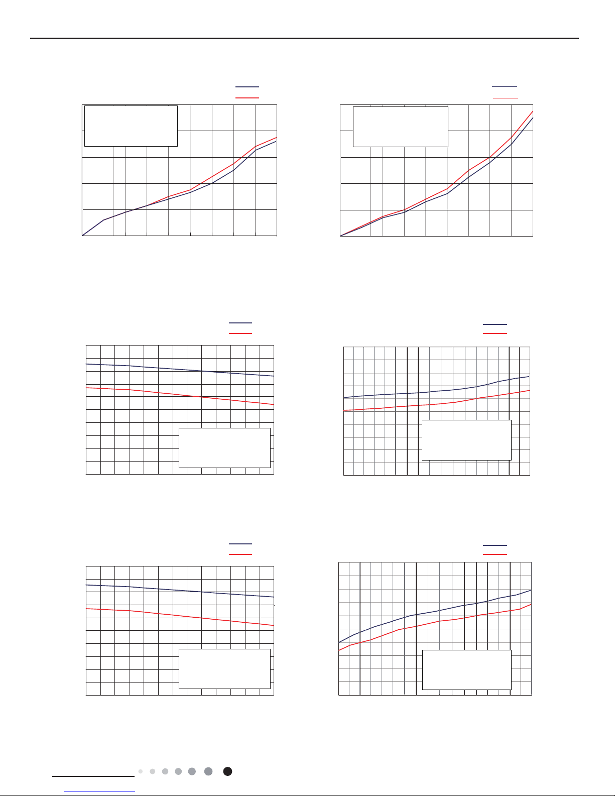
2.2 Operation Characteristic Curve
2.3 Capacity Variation Ratio According to Temperature
Cooling
0
2
4
6
8
10
15020304050 5060 70 80 90 150 20 30 40 60 70 80 90
Compressor speed (rps)
Current (A)
09K
12K
Heating
0
2
4
6
8
10
Compressor speed (rps)
Current (A)
09K
12K
Condition
Indoor:DB27°C WB19°C
Indoor air flow: Super High
Pipe length: 5m
Condition
Indoor:DB20°C WB15°C
Indoor air flow:Super High
Pipe length: 5m
0
20
33 35 37 39 41 43 45
40
60
80
100
120
140
160
180
200
Outdoor temp.(°C)
Capacity ratio(%)
09K
12K
Outdoor temp.(°C)
Outdoor temp.(°C)
09K
12K
Cooling Heating
-6
-4 -2
0
4
0
20
40
60
80
100
120
140
160
180
200
Capacity ratio(%)
2
68
10
0
20
33 35 37 39 41 43 45
40
60
80
100
120
140
160
180
200
Outdoor temp.(°C)
Capacity ratio(%)
09K
12K
Condition
Indoor:DB27°C WB19°C
Indoor air flow: Super High
Pipe length: 5m
09K
12K
Cooling Heating
-20
-18 -14
-10
-2 26
0
20
40
60
80
100
120
140
160
180
200
Capacity ratio(%)
-6
10
Condition
Indoor:DB27°C WB19°C
Indoor air flow: Super High
Pipe length: 5m
Condition
Indoor:DB20°C
WB15°C
Indoor air flow:Super High
Pipe length: 5m
Condition
Indoor:DB20°C
WB15°C
Indoor air flow:Super High
Pipe length: 5m
GWH09TB-S3DNA1D(CB148008401) GWH12TB-S3DNA1D(CB148008301)
GWH09TB-S3DNA1D(CB148008400) GWH09TB-S3DNA2D(CB411002902) GWH09TB-S3DNA3D(CB412003300)
GWH12TB-S3DNA1D(CB148008300) GWH12TB-S3DNA2D(CB411003002) GWH12TB-S3DNA3D(CB412003500)
GWH09TB-S3DNA1E(CB148009300 CB148009301)
10
Technical Information
Service Manual
2.5 Cooling and Heating Data Sheet in Rated Frequency
Rated cooling
condition(°C)
(DB/WB)
Model
Pressure of gas pipe
connecting indoor and
outdoor unit
Inlet and outlet pipe
temperature of heat
exchanger
Fan speed of
indoor unit
Fan speed of
outdoor unit
Compressor
revolution
(rps)
Indoor Outdoor P (MPa) T1 (°C) T2 (°C)
27/19 35/–
09K
0.9~1.2
12 to 14 41 to 43
Super High High
34
12K 10 to 12 43 to 45 55
Rated heating
condition(°C)
(DB/WB)
Model
Pressure of gas pipe
connecting indoor and
outdoor unit
Inlet and outlet pipe
temperature of heat
exchanger
Fan speed of
indoor unit
Fan speed of
outdoor unit
Compressor
revolution
(rps)
Indoor Outdoor P (MPa) T1 (°C) T2 (°C)
20/15 7/6
09K
2.0~2.6
33 to 35 3 to 5
Super High High
41
12K 42 to 44 3 to 5 55
Instruction:
T1: Inlet and outlet pipe temperature of evaporator
T2: Inlet and outlet pipe temperature of condenser
P: Pressure at the side of big valve
Connection pipe length: 5 m.
Cooling:
Heating:
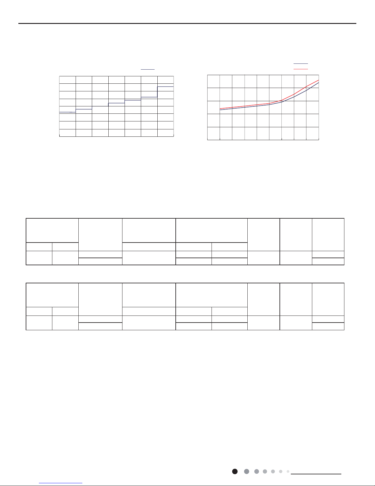
2.4 Noise Curve
SL LMLMMH HSH
30
35
40
45
50
55
Compressor speed (rps)
Noise/dB(A)
09K
12K
0820 30 40 50 60 70 80
90
10
15
20
25
30
35
40
45
50
Indoor fan motor rotating speed (rps)
Noise/dB(A)
09K/12K
Indoor side noise Outdoor side noise
11
Service Manual
Technical Information
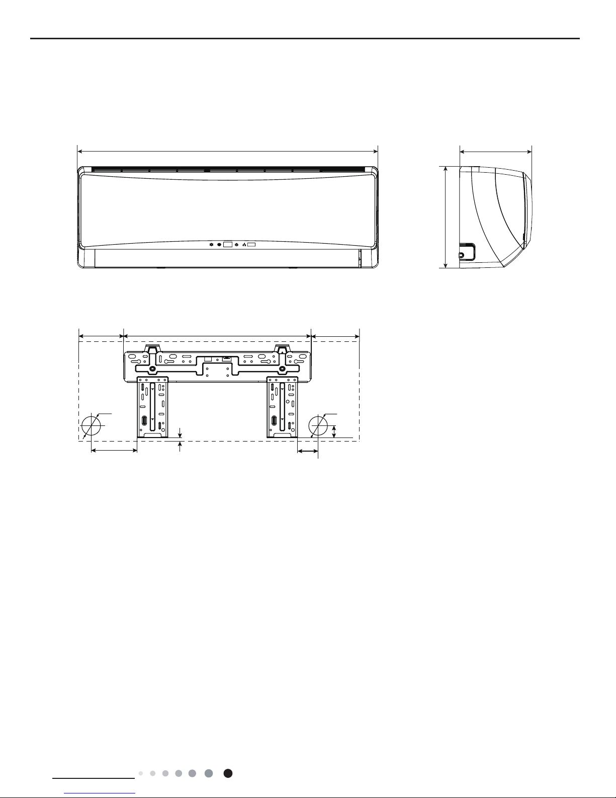
3. Outline Dimension Diagram
3.1 Indoor Unit
Unit:mm
541
866
292
209
162
160
10
80
35
163
Φ55
Φ55

12
Technical Information
Service Manual
3.2 Outdoor Unit
GWH09TB-S3DNA1D/O GWH12TB-S3DNA1D/O GWH09TB-S3DNA1E/O
899
818
303
378
596
596
Unit:mm
13
Service Manual
Technical Information
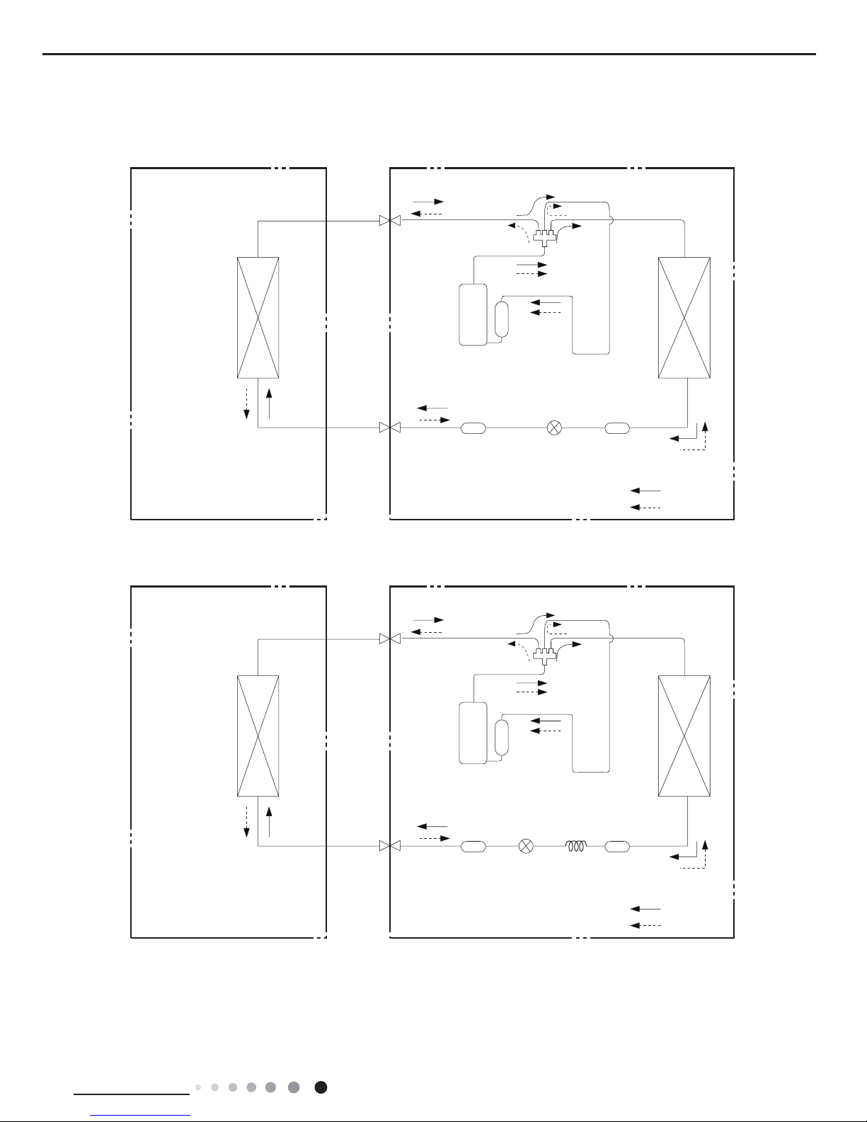
4. Refrigerant System Diagram
Connection pipe specication:
Liquid : 1/4" (6 mm)
Gas : 3/8" (9.52mm) (09K)
Gas : 1/2" (12mm) (12K)
Indoor unit
Outdoor unit
COOLING
HEATING
4-Way valve
Discharge
Suction
Heat
exchanger
(evaporator)
Heat
exchanger
(condenser)
Valve
Valve
Liquid pipe
side
Gas pipe
side
Strainer
Electron
expansion
valve
Strainer
Accumlator
Compressor
Capillary
Indoor unit
Outdoor unit
COOLING
HEATING
4-Way valve
Discharge
Suction
Heat
exchanger
(evaporator)
Heat
exchanger
(condenser)
Valve
Valve
Liquid pipe
side
Gas pipe
side
Strainer
Electron
expansion
valve
Strainer
Accumlator
Compressor
09K
12K
14
Technical Information
Service Manual
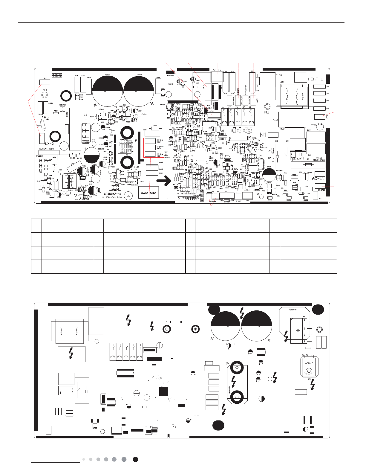
5. Electrical Part
5.1 Wiring Diagram
● Indoor Unit
●Instruction
Symbol Symbol Color Symbol Symbol Color Symbol Name
WH White GN Green CAP Jumper cap
YE Yellow BN Brown COMP Compressor
RD Red BU Blue Grounding wire
YEGN Yellow/Green BK Black / /
VT Violet OG Orange / /
Note: Jumper cap is used to determine fan speed and the swing angle of horizontal lover for this model.
GWH09TB-S3DNA1D/I GWH12TB-S3DNA1D/I GWH09TB-S3DNA2D/
I GWH12TB-S3DNA2D/
I
GWH09TB-S3DNA3D/I GWH12TB-S3DNA3D/I
3OHDVHGRQWWRXFKDQ\
HOHFWURQLFFRPSRQHQWRU
WHUPLQDOZKHQWKHPDFKLQH
LVUXQQLQJVWRSSLQJRU
KDVEHHQSRZHUHGRIIIRU
OHVVWKDQPLQXWHVWR
SUHYHQWHOHFWULFVKRFN
:$51,1*
(/(&75267$7,&
'('867,1*
&211(&725
<(*1
+($/7+/
+($/7+1
%8
5'
*(1(5$725
3/$60$
$1'
%2$5'
7(03
7(03
',63
$3
',63
',63/$<
5(&(,9(5
)$102725
'&02725
78%(
5220
6(1625
6(1625
78%(
57
57
5220
$3
6$
6:,7&+
&211(&725
12
;
&
;
%.
:+
&/($1
0
0
83'2:1
02725
67(33,1*
02725
67(33,1*
02725
83'2:1
/()75,*+7
6:,1*8'
6:,1*8'
67(33,1*
35,17('&,5&8,7%2$5'
-803
&$3
6:,1*/5
0
<(*1
<(*1
%8
%.
%1
287'22581,7
%/2&.
&11(&7,1*
&$%/(
7(50,1$/
1
;7
(9$325$725
3(
%8
%.
%1
1
&20287
$&/
3(
&2/'
&20,11(5
&211(&725
$3
:,5('
&21752//(5
0
6361268404

15
Service Manual
Technical Information
● Outdoor Unit
(1)GWH09TB-S3DNA1D/O(CB148W08400)
(2) GWH09TB-S3DNA1D/O(CB148W08401)
//
:
9
8
29&&203
6$7
2*
:+
/
/;
/;
&1
)$1
&203
0
&203
<9
57
5757
(
(
3(
&2038
$30DLQ%RDUG
%1
%.
%8
5'
<(*1
%8 <( 5'
1
$&/
:$<
$&/
1
1
&208
:,5(
(.9
&1
3(
+($71
+($71
+($7/
/
/ / /
:+
+33
3
&2039 &203:
:+
<(*1
3(
0$*1(7,&
5,1*
1
%/2&.
7(50,1$/
;7
<(*1
3(
%.
%1
%8
RIHOHFWULFVKRFN
PLQXWHVWRSUHYHQWWKHULVN
<(*1
3527(&725
29(5/2$5'
%27721
%$1'+($7(5
&2035(6625
/
1
%$1'
+($7(5
%8
2)$1
&1
6:,7&+
35(6685(
127(
JURXQGRQO\
0RWRU
DSSOLHVWRWKH
LURQVKHOOPRWRU
5'
/
/
/
/
/
. . .
(;3$16,21
9$/9(
:$<
9$/9(
(/(&7521,&
5($&725
97
97
02725
7(037(037(03
28778%(
6(1625
6(1625
(;+$8672875220
6(1625
3OHDVHGRQWWRXFKDQ\
WHUPLQDOZKHQWKHPDFKLQHLV
UXQQLQJVWRSSLQJRUKDVEHHQ
SRZHUHGRIIIRUOHVVWKDQ
:$51,1*
,1'22581,7
1
/
%8
%1
<(*1
32:(5
5($&725
(/(&7521,&
9$/9(
:$<
9$/9(
(;3$16,21
...
/
/
/
/
/
5'
LURQVKHOOPRWRU
DSSOLHVWRWKH
0RWRU
JURXQGRQO\
127(
35(6685(
6:,7&+
2)$1
&1
%8
1
/
1
/
29(5/2$5'
3527(&725
<(*1
PLQXWHVWRSUHYHQWWKHULVN
RIHOHFWULFVKRFN
%8
%1%.
<(*1
%8
%1
%.
3(
32:(5
<(*1
;7
7(50,1$/
%/2&.
1
5,1*
0$*1(7,&
3(
<(*1
7(037(037(03
:+
&203:&2039
3
+33
:+
///
/
28778%(
6(1625
6(1625
(;+$8672875220
6(1625
3(
&1
(.9
:,5(
&208
11
<$:/&$
$&/
1
(<'5%8
<(*1
5'
%8
%.
%1
&2038
3(
(
(
57 57
57
<9
&203
0
&203
)$1
&1
/; /;
/
:+
2*
29&&203
8
9
:
/ /
97 97
02725
$30DLQ%RDUG
6$7
5'
:,5(
;;
<(*1
:$51,1*
SRZHUHGRIIIRUOHVVWKDQ
UXQQLQJVWRSSLQJRUKDVEHHQ
WHUPLQDOZKHQWKHPDFKLQHLV
3OHDVHGRQWWRXFKDQ\
,1'22581,7
63610000249
6361000024901
16
Technical Information
Service Manual
(3) GWH12TB-S3DNA1D/O(CB148W08300)
(4) GWH12TB-S3DNA1D/O(CB148W08301)
5($&725
(/(&7521,&
9$/9(
:$<
9$/9(
(;3$16,21
...
5'
LURQVKHOOPRWRU
DSSOLHVWRWKH
0RWRU
JURXQGRQO\
127(
35(6685(
6:,7&+
%8
1
/
1
/
29(5/2$5'
3527(&725
<(*1
PLQXWHVWRSUHYHQWWKHULVN
RIHOHFWULFVKRFN
%8
%1%.
<(*1
%8
%1
%.
3(
32:(5
<(*1
;7
7(50,1$/
%/2&.
1
5,1*
0$*1(7,&
3(
<(*1
:+
&203:&2039
3
+33
:+
///
3(
&1
(.9
:,5(
&208
11
$&/
:$<
$&/
1
8%(<'5
<(*1
5'
%8
%.
%1
&2038
3(
(
(
5757
57
<9
&203
0
&203
&1
/; /;
/
:+
2*
29&&203
6
5
&
/ /
7979
02725
)$1
6$7
$30DLQ%RDUG
&1
2)$1
6(1625
2875220(;+$867
6(1625
6(1625
28778%(
7(037(03 7(03
; ;
5'
:,5(
/
/
/
<(*1
:$51,1*
SRZHUHGRIIIRUOHVVWKDQ
UXQQLQJVWRSSLQJRUKDVEHHQ
WHUPLQDOZKHQWKHPDFKLQHLV
3OHDVHGRQWWRXFKDQ\
,1'22581,7
//
&
6
5
2*
:+
/
/;
/;
)$1
&203
0
&203
<9
(
(
3(
&2038
$30DLQ%RDUG
%1
%.
%8
<(*1
%8 <( 5'
1
$&/
:$<
$&/
1 1
&208
:,5(
(.9
&1
3(
+($71
+($71
+($7/
/
/ / /
:+
+33
3
&2039 &203:
:+
<(*1
3(
0$*1(7,&
5,1*
1
%/2&.
7(50,1$/
;7
<(*1
32:(5
3(
%.
%1
%8
<(*1
%1%.
%8
RIHOHFWULFVKRFN
PLQXWHVWRSUHYHQWWKHULVN
<(*1
%27720
%$1'+($7(5
&2035(6625
/
1
/
1
%$1'
+($7(5
%8
&1
2)$1
6:,7&+
35(6685(
127(
JURXQGRQO\
0RWRU
DSSOLHVWRWKH
LURQVKHOOPRWRU
/
/
(;3$16,21
9$/9(
:$<
9$/9(
(/(&7521,&
5($&725
97 97
02725
29&&203
&1
57
7575
5' 5'
. . .
7(03
(;+$867
6$7
3527(&725
29(5/2$5'
7(037(03
28778%(
6(1625
6(1625
2875220
6(1625
<(*1
3OHDVHGRQWWRXFKDQ\
WHUPLQDOZKHQWKHPDFKLQHLV
UXQQLQJVWRSSLQJRUKDVEHHQ
SRZHUHGRIIIRUOHVVWKDQ
:$51,1*
,1'22581,7
63610000299
6361000029901
17
Service Manual
Technical Information
The above data is subject to change without notice. Please refer to the nameplate of the unit.
(5) GWH09TB-S3DNA1E/O (CB148W09300)
(6) GWH09TB-S3DNA1E/O (CB148W09301)
//
:
9
8
2*
:+
/
/;
/;
&1
)$1
&203
0
&203
<9
57
7575
(
(
3(
&2038
$30DLQ%RDUG
%1
%.
%8
<(*1
%8 <( 5'
1
$&/
:$<
$&/
1 1
&208
:,5(
(.9
&1
3(
+($71
+($71
+($7/
/
/ / /
:+
+33
3
&2039 &203:
:+
<(*1
3(
0$*1(7,&
5,1*
1
%/2&.
7(50,1$/
;7
<(*1
32:(5
3(
%.
%1
%8
<(*1
%1%.
%8
RIHOHFWULFVKRFN
PLQXWHVWRSUHYHQWWKHULVN
<(*1
%27720
%$1'+($7(5
&2035(6625
/
1
/
1
%$1'
+($7(5
%8
&1
2)$1
6:,7&+
35(6685(
127(
JURXQGRQO\
0RWRU
DSSOLHVWRWKH
LURQVKHOOPRWRU
/
/
/
/
/
. . .
(;3$16,21
9$/9(
:$<
9$/9(
(/(&7521,&
5($&725
97 97
02725
6(1625
2875220 (;+$867
6(1625
6(1625
28778%(
7(03 7(03 7(03
<(*1
3OHDVHGRQWWRXFKDQ\
WHUPLQDOZKHQWKHPDFKLQHLV
UXQQLQJVWRSSLQJRUKDVEHHQ
SRZHUHGRIIIRUOHVVWKDQ
:$51,1*
,1'22581,7
5($&725
(/(&7521,&
9$/9(
:$<
9$/9(
(;3$16,21
...
/
/
/
/
/
LURQVKHOOPRWRU
DSSOLHVWRWKH
0RWRU
JURXQGRQO\
127(
35(6685(
6:,7&+
%8
1
/
1
/
<(*1
PLQXWHVWRSUHYHQWWKHULVN
RIHOHFWULFVKRFN
%8
%1%.
<(*1
%8
%1
%.
3(
32:(5
<(*1
;7
7(50,1$/
%/2&.
1
5,1*
0$*1(7,&
3(
<(*1
:+
&203:&2039
3
+33
:+
///
/
3(
&1
(.9
:,5(
&208
11
<$:/&$
$&/
1
(<'5%8
<(*1
%8
%.
%1
&2038
3(
(
(
5757
57
<9
&203
0
&203
&1
/; /;
/
:+
2*
8
9
:
/ /
7979
02725
)$1
$30DLQ%RDUG
6(1625
2875220(;+$867
6(1625
6(1625
28778%(
7(037(03 7(03
; ;
5'
:,5(
<(*1
&1
2)$1
:$51,1*
SRZHUHGRIIIRUOHVVWKDQ
UXQQLQJVWRSSLQJRUKDVEHHQ
WHUPLQDOZKHQWKHPDFKLQHLV
3OHDVHGRQWWRXFKDQ\
,1'22581,7
6361000024902
6361000024903
18
Technical Information
Service Manual
5.2 PCB Printed Diagram
● Top view
● Bottom view
Indoor Unit
1 Neutral wire
2 DC fan
3 Interface of inching switch
4 Interface of electrostatuc dedusting
5 Auto button
6 Small up&down swing
7 Left&right swing
8 Big up&down swing
9 Display interface
10 Jumper interface
11 Ambient temperature sensor
12 Tube temperature sensor
13
Communication interface between
indoor unit and outdoor unit
14 Fuse
15 Interface of live wire for indoor unit
16
Power suppy interface of outdoor
unit
17 Healthy neutral wire
18 Healthy live wire
1234567
8
9
10
1112
13
14
15
17
18
19
Service Manual
Technical Information
1
23 4567 8
9
10
11
12
13141516
● Top view
● Bottom view
Outdoor Unit
1
Terminal of reactor
wire
5
Neutral wire interface for electric
heating of compressor
9 Earthing wire terminal 13
High-pressure switch
terminal
2
Terminal of electronic
expansion valve
6
Neutral wire interface of electric
heating belt for chassis
10 Neutral wire terminal 14
Terminal of temperature
sensor wire
3 Fan terminal 7
Neutral wire terminal of 4-way
valve
11 Live wire terminal 15
Terminal of overload
wire
4
Terminal of live wire
for 4-way valve
8
Live wire terminal of electric
heating
12
Communication wire terminal
for indoor unit and outdoor unit
16
Terminal of compressor
wire
20
Technical Information
Service Manual
6. Function and Control
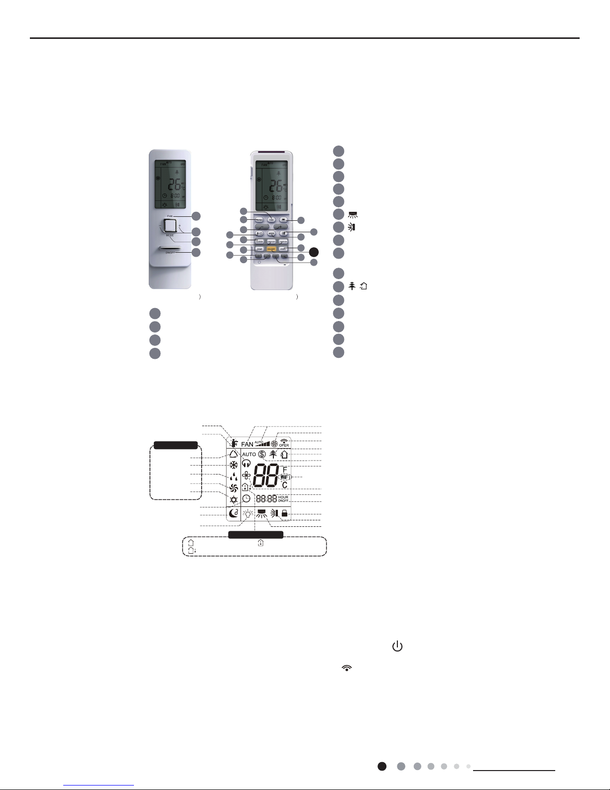
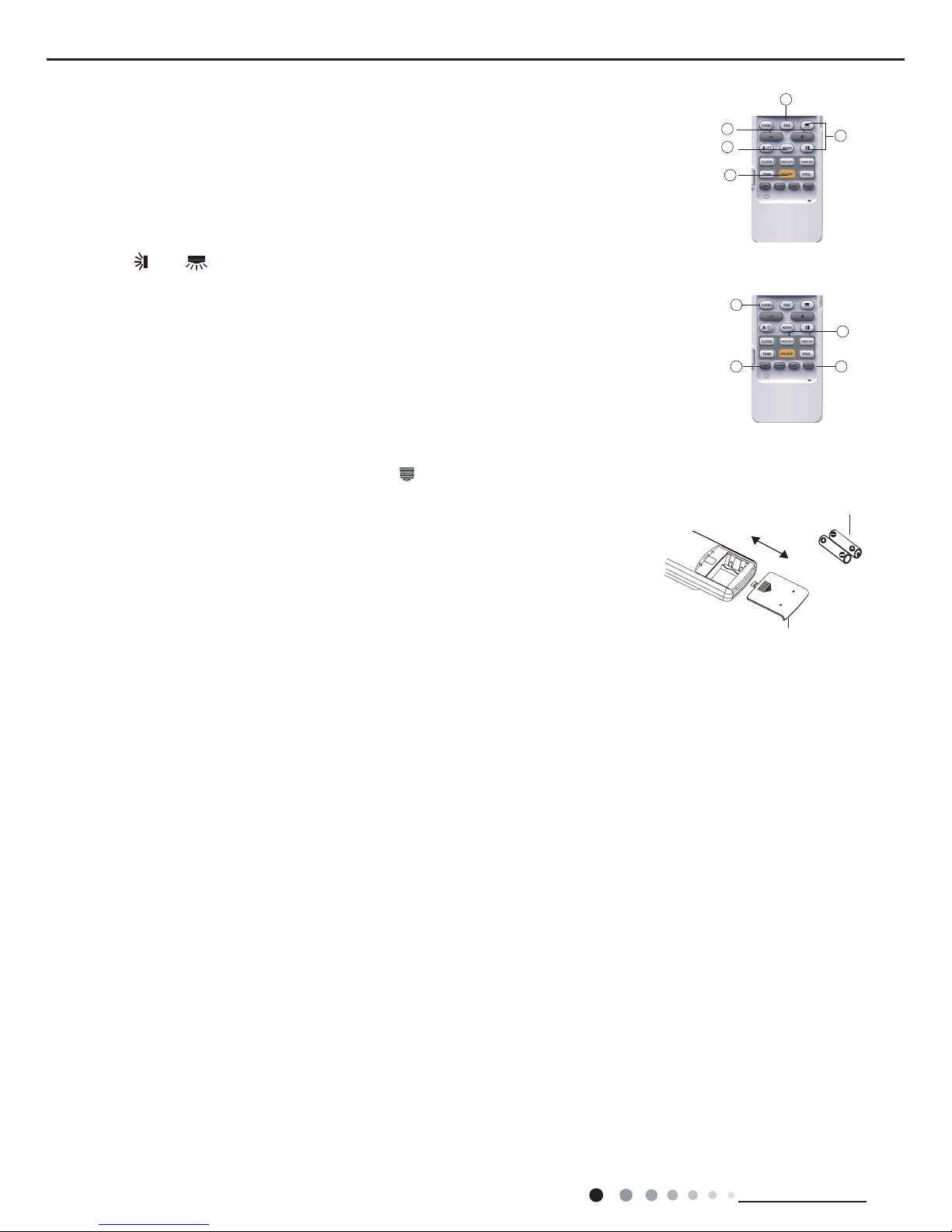
6.1 Remote Controller Introduction
1
2
3
4
5
6
7
8
9
10
11
12
button
button
X-FAN button
QUIET button
SLEEP button
TEMP button
I FEEL button
13
14
15
16
TURBO button
LIGHT button
button
TIMER ON/
TIMER OFF button
CLOCK button
1
2
3
4
ON/OFF button
FAN button
+/- button
MODE button
ON/OFF button
FAN button
+/- button
MODE button
3
4
2
1
(before opening cover (after opening cover
/
1
15
5
2
6
3
12
16
4
11
8
9
13
7
10
14
1
2
3
4
5
6
7
8
9
10
11
12
button
button
X-FAN button
QUIET button
SLEEP button
TEMP button
I FEEL button
13
14
15
16
TURBO button
LIGHT button
button
TIMER ON/
TIMER OFF button
CLOCK button
1
2
3
4
ON/OFF button
FAN button
+/- button
MODE button
ON/OFF button
FAN button
+/- button
MODE button
3
4
2
1
(before opening cover (after opening cover
/
Send signal
Turbo mode
8ć heating function
Set temperature
Set time
X-FAN function
TIMER ON /TIMER OFF
Child lock
Up & down swing
Left & right swing
Set fan speed
Light
Temp. display type
: Set temp.
: Outdoor ambient temp.
: Indoor ambient temp.
Sleep mode
Clock
Heat mode
Fan mode
Dry mode
Cool mode
Auto mode
Operation mode
I feel
Healthy mode
Scavenging functions
Quiet
1
15
5
2
6
3
12
16
4
11
8
9
13
7
10
14
This is a general remote controller. Some
models have this function while some do
not. Please refer to the actual models.
Buttons on Remote Controller
Introduction for Icons on Display Screen
Introduction for Buttons on Remote Controller
● After putting through the power, the air conditioner will give out a sound.Operation indictor " " is ON (red indicator). After that, you can
operate the air conditioner by using remote controller.
● Under on status, pressing the button on the remote controller, the signal icon " " on the display of remote controller will blink once and
the air conditioner will give out a “de” sound, which means the signal has been sent to the air conditioner.
● Under off status, set temperature and clock icon will be displayed on the display of remote controller (If timer on, timer off and light
functions are set, the corresponding icons will be displayed on the display of remote controller at the same time); Under on status, the
display will show the corresponding set function icons.
1. ON/OFF button
Press this button, the unit will be turned on, press it once more, the unit will be turned off. Sleep function will be canceled, while unit off.
Note:
● This is a general use remote controller, it could be used for the air conditioners with multifunction; For some function, which the model
dont have, if press the corresponding button on the remote controller that the unit will keep the original running status.
21
Service Manual
Technical Information
2. FAN button
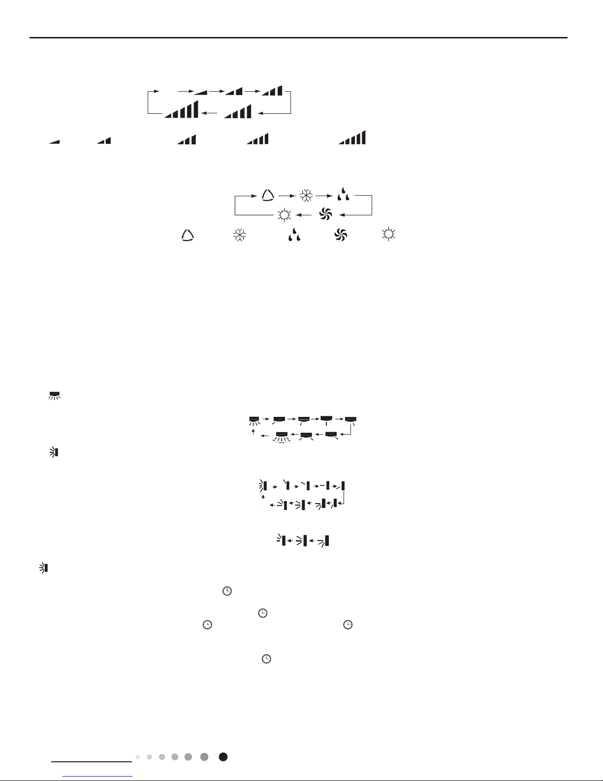
Press this button, Auto, Low, Medium-low, Medium, Medium-high, High speed can be circularly selected. After powered on, Auto fan speed is
default. Under DRY mode, Low fan speed only can be set up.
3. MODE button
Press this button, Auto, Cool, Dry, Fan, Heat mode can be selected circularly. Auto mode is default while power on. Under Auto mode, the
temperature will not be displayed;Under Heat mode, the initial value is 28°C( 82°F);Under other modes, the initial value is 25°C(77°F).
4. +/- button
● Presetting temperature can be increased.
Press this button,the temperature can be set up, continuously press this button and hold for two seconds, the relative contents can quickly
change,until unhold this button and send the order that the °C(°F) signal will be displayed all the time.The temperature adjustment is unavilable
under the Auto mode, but the order can be sent by if pressing this button.Temperature of Celsius degree setting:16-30;for Fahrenheit degree
setting:61-86.
● Presetting temperature can be decreased.
Press this button, the temperature can be set up, continuously press this button and hold for two seconds, the relative contents can quickly
change,until unhold this button and send the order that the°C(°F) signal will be displayed all the time.The temperature adjustment is
unavailable under the Auto mode,but the order can be sent by if pressing this button.
5. TURBO button
Under Cool or Heat mode,press this button can turn on or turn off the Turbo function.After the Turbo function turned on, the signal of Turbo will
display. The signal will be automatically cancelled if changing the mode or fan speed.
6. button
Press this button to set left & right swing angle cycling as below:
7. button
Press this button to set swing angle,which circularly changes as below:
This remote controller is universal. If it receives threes kinds of following status,the swing angle will remain origial.
If guide louver is stopped when it is swinging up and down,it will remain its present position.
indicates guide louver swings back and forth in the ve places,as shown in the gure.
8. CLOCK button
Press this button, the clock can be set up,signal blink and display.Within 5 seconds, the value can be adjusted by pressing + or - button,
if continuously press this button for 2 seconds above,in every 0.5 seconds, the value on ten place of Minute will be increased 1.During
blinking,repress the Clock button or Conrm button,signal will be constantly displayed and it denotes the setting succeeded. After powered
on, 12:00 is defaulted to display and signal will be displayed. If there is signal be displayed that denotes the current time value is Clock
value, otherwise is Timer value.
9. TIMER ON/TIMER OFF button
● Timer On setting: Signal “ON”will blink and display,signal will conceal,the numerical section will become the timer on setting status.
During 5 seconds blink,by pressing + or - button to adjust the time value of numerical section,every press of that button,the value will be
increased or decreased 1 minute.Hold pressing + or - button,2 seconds later,it quickly change,the way of change is: During the initial 2.5
seconds,ten numbers change in the one place of minute,then the one place is constant,ten numbers change in the ten splace of minute at 2.5
seconds speed and carry. During 5s blink,press the Timer button,the timer setting succeeds.The Timer On has been set up,repress the timer
button,theTimer On will be canceled. Before setting theTimer,please adjust the Clock to the current actual time.
● One press this key to enter into TIMER OFF setup, in which case the TIMER OFF icon will blink. The method of setting is the sameas for
TIMER ON.
Note: Its Low fan speed
under Dry mode.
(only for cooling and heating unit.
As for cooling only unit, it wont
have any action when it receives
the signal of heating operation.)
Medium fanLow fan High fan
Medium-low fan Medium-high fan
ATUO
Medium fanLow fan High fan
Medium-low fan Medium-high fan
ATUO
AUTO COOL DRY FAN HEAT
OFF
OFF
OFF
OFF
F
OFF
OFF
OFF
OFF
OFF
OFF
OFF
OFF
22
Technical Information
Service Manual
10. TEMP button
Press this button, you can see indoor set temperature, indoor ambient temperature or outdoor ambient temperature on indoor units
display. The setting on remote controller is selected circularly as below:
no display
When selecting " " with remote controller or no display, temperature indicator on indoor unit displays set temperature; When selecting
" " with remote controller,temperature indicator on indoor unit displays indoor ambient temperature; When selecting " " with remote
controller, temperature indicator on indoor unit displays outdoor ambient temperature. 3s later it will return to the setting temprature or it
depends on the other received signal within 3s.
Attention: When displaying the outdoor ambient, the displaying range is 32-99°F and 0-60°C.When it goes beyond the range, it keeps the
threshold data (the smallest—0°C or 32°F and the largest 99°F or 60°C).
Warm tips: When operating buttons on the cover please make sure the cover is closed completely.
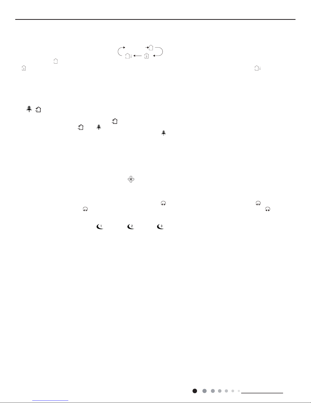
11.
/
button(This function is only available for some models)
Press this button to achieve the on and off of healthy and scavenging functions in operation status.Press this button for the rst
time to start scavenging function;LCD displays“
”.Press the button for the second time to start healthy and scavenging functions
simultaneously;LCD displays“
”and “
” .Press this button for the third time to quit healthy and scavenging functions simultaneously.
Press the button for the fourth time to start healthy function; LCD display“
” .Press this button again to repeat the operation above.
12. I FEEL button
Press this button once, to turn on the I FEEL function, then the gure of "I FEEL" will be displayed, after every press of other function
button, every 200ms to send I FEEL once, after this function started,the remote control will send temperature to the main un it in every 10
minutes.When repress this button, this function will be turned off.
13. LIGHT button
Press this button at unit On or Off status,Light On and Light Off can be set up.After powered on, Light On is defaulted.
14. X-FAN button
Pressing X-FAN button in COOL or DRY mode,the icon
is displayed and the indoor fan will continue operation for 2 minutes in order
to dry the indoor unit even though you have turned off the unit.After energization, X-FAN OFF is defaulted.X-FAN is not available in
AUTO,FAN or HEAT mode.
15. QUIET button
Press this button,the Quiet status is under the Auto Quiet mode (display"
" and “Auto”signal ) and Quiet mode(display "
" singal) and
Quiet OFF(there is no signal of "
" displayed),after powered on,the Quiet OFF is defaulted. Under the Quiet mode (Display "
"signal),
the fan speed is not available.
16. SLEEP button
●Press this button, can select Sleep 1 ( ), Sleep 2 ( ),Sleep 3 (
) and cancel the Sleep, circulate between these, after
electried, Sleep Cancel is defaulted.
●Sleep 1 is Sleep mode 1, in Cool, Dehumidify modes: sleep status after run for one hour, the main unit setting temperature will increase
1°C(1ºF~2ºF), 2 hours,setting temperature increased 2°C(3ºF~4ºF), the unit will run at this setting temperature; In Heat mode: sleep status
after run for one hour, the setting temperature will decrease 1°C(1ºF~2ºF), 2 hours, setting temperature will decrease 2°C(3ºF~4ºF), then
the unit will run at this setting temperature.
●Sleep 2 is sleep mode 2, that is air conditioner will run according to the presetting a group of sleep temperature curve.
In Cool mode:
(1) When setting the initial temperature 16~23°C(61ºF~74ºF), after turned on Sleep function, the temperature will be increased 1°C(1ºF~2ºF)
in every hour,after 3°C(5ºF~6ºF) the temperature will be maintained, after 7hours,the temperature will be decreased 1°C(1ºF~2ºF), after
that the unit will keep on running under this temperature;
(2) When setting the initial temperature 24~27°C(75ºF~81ºF), after turned on Sleep function, the temperature will be increased 1°C(1ºF~2ºF)
in every hour,after 2°C(3ºF~4ºF) the temperature will be maintained, after 7hours,the temperature will be decreased 1°C(1ºF~2ºF) , after
that the unit will keep on running under this temperature;
(3) When setting the initial temperature 28~29°C(82ºF~85ºF), after turned on Sleep function, the temperature will be increased 1°C(1ºF~2ºF)
in every hour, after 1°C(1ºF~2ºF) the temperature will be maintained, after 7hours,the temperature will be decreased 1°C(1ºF~2ºF) , after
that the unit will keep on running under this temperature;
(4) When setting the initial temperature 30°C(86ºF), under this temperature setting, after 7hours, the temperature will be decreased
1°C(1ºF~2ºF), after that the unit will keep on running under this temperature;
In Heat mode:
(1) Under the initial presetting temperature 16°C(61ºF), it will run under this setting temperature all along.
(2) Under the initial presetting temperature17~20°C(62ºF~68ºF), after Sleep function started up, the temperature will decrease 1°C(1ºF~2ºF)
in every hour, after 1°C(1ºF~2ºF) decreased, this temperature will be maintained.
(3) Under the initial presetting temperature 21~27°C(69ºF~81ºF), after Sleep function started up, the temperature will decrease
1°C(1ºF~2ºF) in every hour,after 2°C(3ºF~4ºF) decreased, this temperature will be maintained.
(4) Under the initial presetting temperature 28~30°C(82ºF~86ºF), after Sleep function started up, the temperature will decrease
1°C(1ºF~2ºF) in every hour, after 3°C(5ºF~6ºF) decreased, this temperature will be maintained.

23
Service Manual
Technical Information
●Sleep 3- the sleep curve setting under Sleep mode by DIY:
(1) Under Sleep 3 mode, press "Turbo" button for a long time, remote control enters into user individuation sleep setting status, at this
time, the time of remote control will display "1hour ", the setting temperature "88" will display the corresponding temperature of last setting
sleep curve and blink (The rst entering will display according to the initial curve setting value of original factory);
(2) Adjust "+" and "-" button, could change the corresponding setting temperature, after adjusted, press "Trubo "button for conrmation;
(3) At this time, 1hour will be automatically increased at the timer postion on the remote control, (that are "2hours" or "3hours" or "8hours "),
the place of setting temperature "88" will display the corresponding temperature of last setting sleep curve and blink;
(4) Repeat the above step (2)~(3) operation, until 8hours temperature setting nished, sleep curve setting nished, at this time, the remote
control will resume the original timer display;temperature display will resume to original setting temperature.
●Sleep3- the sleep curve setting under Sleep mode by DIY could be inquired:
The user could accord to sleep curve setting method to inquire the presetting sleep curve, enter into user individuation sleep setting
status, but do not change the temperature, press "Turbo" button directly for conrmation.
Note: In the above presetting or enquiry procedure, if continuously within10s, there is no button pressed, the sleep curve setting status will
be automatically quit and resume to display the original displaying. In the presetting or enquiry procedure, press "ON/OFF" button, "Mode"
button, "Timer" button or "Sleep" button, the sleep curve setting or enquiry status will quit similarly.
17. About X-FAN function
This function indicates that moisture on evaporator of indoor unit will be blowed after the unit is stopped to avoid mould.
(1)Having set X-FAN function on: After turning off the unit by pressing ON/OFF button indoor fan will continue running for about 2 min. at
low speed. In this period, press X-FAN button to stop indoor fan directly.
(2)Having set X-FAN function off: After turning off the unit by pressing ON/OFF button, the complete unit will be off directly.
18. About AUTO RUN
When AUTO RUN mode is selected, the setting temperature will not be displayed on the LCD, the unit will be in accordance with the room
temp. automatically to select the suitable running method and to make ambient comfortable.
19. About turbo function
If start this function, the unit will run at super-high fan speed to cool or heat quickly so that the ambient temp. approachs the preset temp.
as soon as possible.
20. About lock
Press + and - buttons simultaneously to lock or unlock the keyboard. If the remote controlleris locked, the icon
will be displayed on it, in
which case, press any button, the mark will icker for three times. If the keyboard is unlocked, the mark will disappear.
21. About swing up and down
(1)Press swing up and down button continuously more than 2s,the main unit will swing back and forth from up to down, and then loosen
the button, the unit will stop swinging and present position of guide louver will be kept immediately.
(2)Under swing up and down mode, when the status is switched from off to
OFF
, if press this button again 2s later,
OFF
status will switch
to off status directly; if press this button again within 2s,the change of swing status will also depend on the circulation sequence stated
above.
22. About swing left and right
(1)Press swing left and right button continuously more than 2s,the main unit will swing back and forth from left to right, and then loosen the
button, the unit will stop swinging and present position of guide louver will be kept immediately.
(2)Under swing left and right mode, when the status is switched from off to
, if press this button again 2s later,
status will switch
to off status directly; if press this button again within 2s,the change of swing status will also depend on the circulation sequence stated
above.
23. About switch between Fahrenheit and Centigrade
Under status of unit off, press MODE and - buttons simultaneously to switch °C and °F.
24. Combination of " TEMP" and "CLOCK" buttons : About Energy-saving Function
Press “TEMP” and “CLOCK” simultaneously in COOL mode to start energy-saving function.Nixie tube on the remote controller displays “SE”.
Repeat the operation to quit the function.
25. Combination of " TEMP" and "CLOCK" buttons : About 8°C(46ºF) Heating Function
Press “TEMP” and “CLOCK” simultaneously in HEAT mode to start 8°C(46ºF) Heating Function.Nixie tube on the remote controller
displays"
"and a selected temperature of “8°C” (46°F if Fahrenheit is adopted). Repeat the operation to quit the function.
26. About Auto Quiet function
When auto quiet function is selected:
(1)Under cooling mode: indoor fan operates at notch 4 speed. 10 minutes later or when indoor ambient temperature≤28°C(82ºF), indoor
fan will operate at notch 2 speed or quiet mode according to the comparison between indoor ambinet temperature and set temperature.
(2)Under heating mode: indoor fan operates at notch 3 speed or quiet mode according to the comparison between indoor ambient
temperature and set temperature.
(3)Under dry, fan mode: indoor fan operates at quiet mode.
(4)Under auto mode: the indoor fan operates at the auto quiet mode according to actual cooling, heating or fan mode.
27. About Sleep function
Under the Fan and Auto mode, the Sleep function cannot be set up, under Dehumidify mode, only Sleep 1 can be selected.Select and
enter into any kind of Sleep mode, the Quiet function will be attached and stared, different Quiet status could be optional and turned off.
24
Technical Information
Service Manual
1
4
3 1
2
4
2
3
5
battery
Cover of battery box
remove
reinstall
1
4
3 1
2
4
2
3
5
battery
reinstall
1
4
3 1
2
4
2
3
5
Operation Guide
Replacement of Batteries in Remote Controller
1. General operation
(1)After powered on, press ON/OFF button, the unit will start to run. (Note: When it is powered on, the
guide louver of main unit will close automatically.)
(2)Press MODE button, select desired running mode.
(3)Pressing + or - button, to set the desired temperature (It is unnecessary to set the temp. at AUTO
mode.)
(4)Pressing FAN button, set fan speed, can select AUTO FAN, LOW, MEDIUM-LOW, MEDIUM, MEDIUM-
HIGH and HIGH.
(5)Pressing and button, to select the swing.
2. Optional operation
(1)Press SLEEP button, to set sleep.
(2)Press TIMER ON and TIMER OFF button, can set the scheduled timer on or timer off.
(3)Press LIGHT button, to control the on and off of the displaying part of the unit (This function may be not
available for some units).
(4)Press TURBO button, can realize the ON and OFF of TURBO function.
1. Press the back side of remote controller marked with " ",as shown in the g,and then push out the
cover of battery box along the arrow direction.
2. Replace two 7# (AAA 1.5V) dry batteries, and make sure the position of "+" polar and "-" polar are
correct.
3. Reinstall the cover of battery box.
Note:
● During operation, point the remote control signal sender at the receiving window on indoor unit.
● The distance between signal sender and receiving window should be no more than 8m, and there
should be no obstacles between them.
● Signal may be interfered easily in the room where there is uorescent lamp or wireless telephone;
remote controller should be close to indoor unit during operation.
● Replace new batteries of the same model when replacement is required.
● When you dont use remote controller for a long time, please take out the batteries.
● If the display on remote controller is fuzzy or theres no display, please replace batteries.
OFF
25
Service Manual
Technical Information
6.2 Brief Description of Modes and Functions
●
Indoor Unit
●
Indoor Unit
1Temperature Parameters
ƹ
Indoor preset temperature (Tpreset)
ƹ
Indoor ambient temperature (Tamb.)
2 Basic function
s (The temperature in this manual is expressed by Centigrade. If Fahrenheit is used, the switchover between them is
Tf=TcX1.8+32.)
Once the compressor is energized, there should be a minimum in
terval of 3 minutes between two start-ups. But if the unit is
de-energized and then energized, the compressor can restart
within 3 minutes.
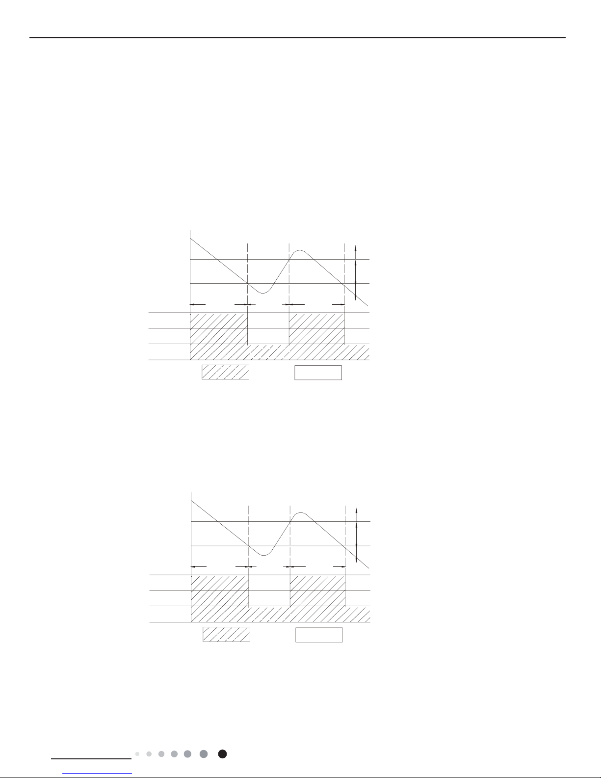
2.1 Cooling mode
2.1.1 Cooling conditions and process
When
Tamb. ≥Tpreset, the unit starts cooling operation. In this case, the compressor and the outdoor fan operate and the indoor fan
operates at set speed.
When Tamb. ≤Tpreset-3
ć, the compressor and the outdoor fan stop while the indoor fan runs at set speed.
When Tpreset-
3ć˘Tamb. ˘Tpreset, the unit will maintain its previous running status.
In cooling mode, temperature setting range is 1
630ć; the indoor unit displays operation icon, cooling icon and set temperature.
2.1.2
When outdoor unit has malfunction or stops for protection, indoor unit will keep previous operation status and display malfunction
code.
2.1.3 The protection status is as the same as the cooling mode.
2.2 Dr
y Mode
2.2.1 Dr
y Conditions and Process
2.3 Heating mode (not available for cooling only
type)
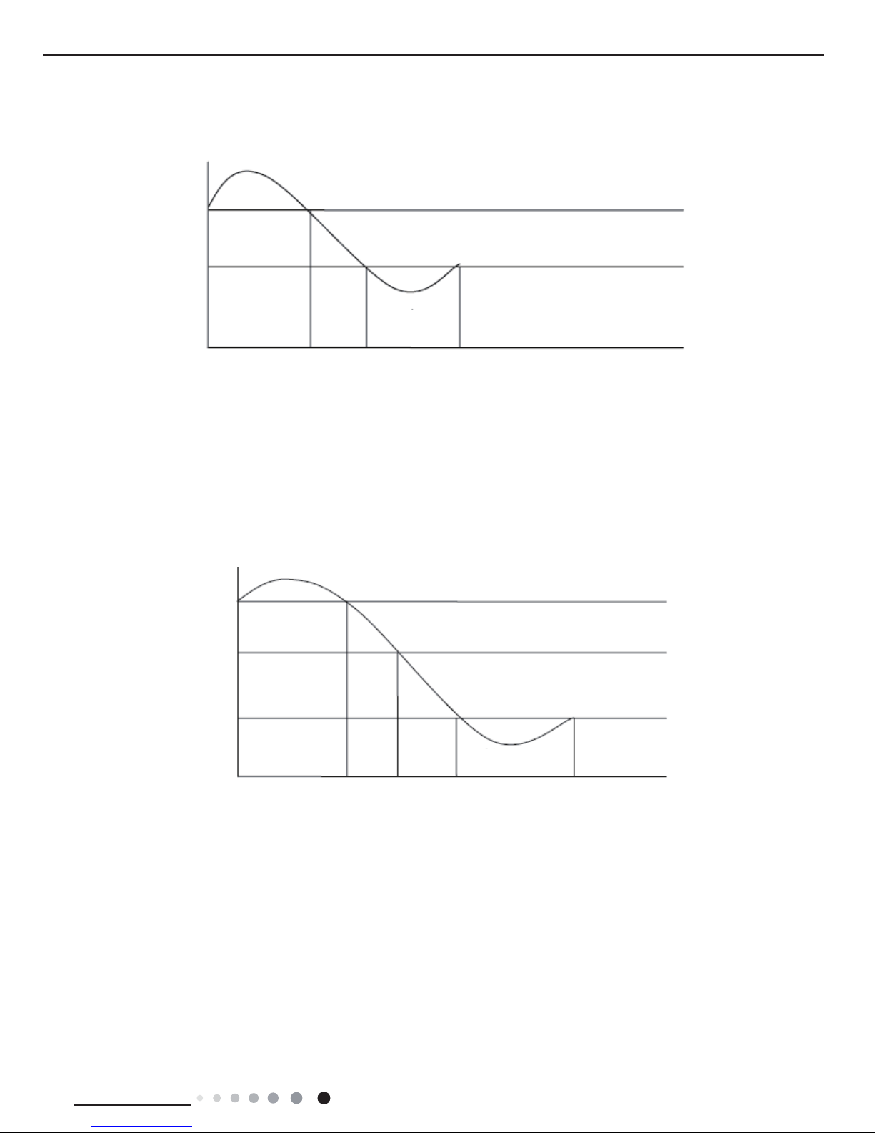
2.3.1 Heating conditions and process
When
Tamb. ≤Tpreset+2ć, the unit starts heating operation. In this case, compressor and outdoor fan operate simultaneously; the
indoor fan operates at cold-air prevention mode.
When Tamb≥Tpreset+5
ć, the compressor and outdoor fan stop operation; the indoor fan blows residual heat.
When T
preset
+2ć˘T
amb.
˘ T
preset
+5ć, the unit will maintain its previous running status.
Under this mode, temperature setting range is 1630ć; the indoor unit displays operation icon, heating icon and set temperature.
Tpreset
Tpreset –3 ˚C
Compressor
Outdoor fan
Indoor fan
Run
Tamb.
Stop
Stop cooling
Start cooling
Previous running status
≥ 6 min. ≥ 3 min. ≥ 6 min.
Set fan speed
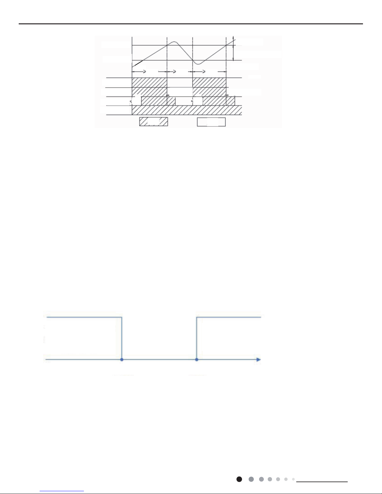
When Tamb.>Tpreset, the unit operates in cooling mode. Meanwhile, compressor and outdoor fan operate, and indoor fan operates a
t
set fan speed (low fan speed, quiet fan speed or auto quiet fan speed).When Tpreset-2
℃<Tamb. ≤Tpreset, the unit keeps previous
operation status.When Tamb. ≤Tpreset-2
℃, compressor, outdoor fan and indoor fan operate at set fan speed (low fan speed, quiet fan
speed or auto quiet fan speed).Under this mode, the temperature setting range is 1
6~30℃
. Display displays operation icon, drying icon
and set temperature.
Tpreset
Tpreset –2˚C
Compressor
Outdoor fan
Indoor fan
Run
Tamb.
Stop
Stop cooling
Start cooling
Previous running status
≥ 6 min. ≥ 3 min. ≥ 6 min.
Set fan speed
26
Technical Information
Service Manual
2.3.2 Defrosting and Oil Return
When receiving the signal of defrosting and oil return, the horizontal louver(big one)
will rotate to the position where the angle is
minimum and the other horizontal louver(small one) w
ill close. In 10 seconds later, indoor fan will stop operation. During defrosting, oi
l
return and 5 minutes after quit, all indoor pipe temperature sensors
will not be detected. When receiving oil return signal or defrosting
signal sent by outdoor unit, “dual 8” nixie tube
will display “H1”. (H1 is not malfunction code.)
2.3.3 Bl
ow residual heat
In heating mode,
when temperature reaches the set temperature, the compressor and outdoor fan will stop.
The horizontal louver (big one)
will rotate to the default position for cooling and the other one (small one) will close. Indoor unit will
operate at set speed for 60s and then stop operation.
When the unit is in heating mode or auto heating mode, and also
the compressor and indoor fan are operating, if turning off the unit,
compressor and outdoor fan will stop. Horizontal louver (big one)
will rotate to the position where gentle wind is blown out (default
position
for cooling) and the other horizontal louver (small one) will close. Indoor unit will operate at low speed for 10 seconds and
then
the unit
will be turned off.
2.4 Fan Mode
In this mode, indoor fan operates at set speed
while compressor and outdoor fan stop operation. The set temperature range is
16~3
0ć. Operation icon and set temperature are displayed.
2.5 Auto Mode
In this mode, operation mode (Cool, Heat, Fan)
will be automatically selected according to change of ambient temperature. Operation
icon, actual operation icon and set temperature
will be displayed. There is 30s delay for protection when changing mode. The
protection function is as the same as that under each mode.
2.5.1 When Tamb.≥26
ćˈthe unit will operate at cooling mode, the default set temperature is 25ć.
2.5.2
When Tamb. ≤21ćˈthe unit will operate at heating mode, the default set temperature is 20ć˄if the cooling only unit operates at
fan mode, the default set temperature is 25
ć.˅;
2.5.3 When 22
ć ≤Tamb. ≤25ćˈand the unit is turned on for the first time, if it changes to auto mode from other mode, the previous
operation mode
will be maintained; If it changes to auto mode from dry mode, the unit will operate at fan mode.
2.5.4 When the unit operates at auto mode, the frequency of compressor is as the same as that under cooling mode,
while it is as the
same as that under heating mode.
Protection function
A.
Under cooling mode, the protection function is as the same as that under cooling mode.
B.
Under heating mode, the protection function is as the same as that under heating mode.
2.6. “8
ć” Heating
Under heating mode, press buttons “Temp” and “Clock” simultaneously
, the 8ć heating function will be activated and “cold air
prevention”
will be shielded.
2.6.1 8
ć heating can’t co-exist with sleep function. If 8ćheating function is set, it can be cancelled by pressing sleep button, In that
case, the set temperature
will be that before entering 8 ć heating; If sleep function is set, press buttons “Temp” and “Clock”
simultaneously to activate
8ć function and cancel sleep function at the same time.
2.6.2 Set temperature is 8
ćˈand it is displayed on the indoor display panel.
2.6.3 In this mode, TURBO can’t be se
t and fan speed can’t be adjusted.
2.6.4 In this mode,
when compressor operates, fan speed will be adjusted as follows; when compressor stops operation, indoor unit
wi
ll operate at blowing residual heat.
When Tindoor amb. ≤9ć, indoor unit will operate at high speed;
Heating mode Tpreset
=20ć (if cooling-only
unit, it is Fan mode,
T
p
reset=25ć˅
Keep current
operation mode
Cooling mode,
Tpreset=25ć
Tpreset
Tpreset +2 ˚C
Tpreset +5 ˚C
Tamb.
Compressor
Outdoor unit
Indoor unit
4-way valve
6 min.3 min.
2 min.
2 min.
Blow residual
heat
6 min.
Start heating
Previous running status
Start heating
Blow residual heat
Stop
Run
21℃ 26℃
27
Service Manual
Technical Information
When 9ć ˘Tindoor amb.˘11ć, indoor unit will operate at medium speed;
When Tindoor amb.≥1
1ćˈindoor fan will operate at low speed;
When changing among lo
w high, medium, and low speeds, the minimum operation time is 210 seconds.
2.6.5 If the unit has memory function,
8ćheating function will be memorized.
2.7 Energy-saving Function
2.7.1 In cooling mode,
when receiving command of energy-saving sent by remote control, the controller enters energy-saving mode; If
the unit is under energy-saving mode already,
such command will not be executed.
2.7.2 When remote control is set to display set temperature, “dual 8”nixie tube displays “SE”.
2.7.3 In this mode,
when compressor operates, fan speed will be adjusted according to auto fan mode under energy-saving operation;
wh
en compressor stops operation, indoor fan will operate at low speed.
a. When Tamb.≥31
ć, indoor fan will operate at super high speed;
b. When 31
ć˚Tamb.≥Tpreset + 3ć, indoor fan will operate at high speed;
c. When Tpreset+1
ć˘Tamb.˘Tpreset + 3ćˈindoor fan will operate at medium speed;
d. When Tamb.≤Tpreset +
1ćˈ indoor fan will operate at low speed;
Note:
The switchover among superhigh speed, high speed, medium speed and low speed requires minimum 210seconds of operation.
2.7.4 In this mode, set temperature
will be automatically adjusted according to actual operation conditions.
3 Other Control
3.1 Timer function
General timer and clock timer functions are compatible by equipping remote controller
with different functions.
3.1.1 General Timer
Ti
mer ON can be set at unit OFF. If selected ON time is reached, the unit will start to operate according to previous setting status. Time
setting range is 0.5-24hr in 30-minute increments.
Timer
OFF can be set at unit ON. If selected OFF time is reached, the unit will stop operation. Time setting range is 0.5-24hr in
30-minute increments.
3.1.2 Clock Timer
Timer ON
If
timer ON is set during operation of the unit, the unit will continue to operate. If timer ON is set at unit OFF, upon ON time reaches the
unit
will start to operate according to previous setting status.
Ti
mer OFF
If timer OFF is set at unit OFF, the sy
stem will keep standby status. If timer OFF is set at unit ON, upon OFF time reaches the unit will
stop operation.
Tamb.
Fan speed
Low
Med.
High
Tamb.
Tpreset + 3 ć
31℃
11℃
9℃
Tp ć
Fan speed
Super high
High
Med.
Low
reset + 1
 Loading...