

Gree GWH09RB-K3DNA3G, GWH12RB-K3DNA3G Service Manual

GREE ELECTRIC APPLIANCES,INC.OF ZHUHAI
Change for Life
Service Manual
GWH09RB-K3DNA3G
GWH12RB-K3DNA3G
(Refrigerant:R410A)
Models:

Service Manual
Table of Contents
Table of Contents
Part
Ⅰ
: Technical Information
.......................................................................1
1. Summary
......................................................................................................................1
2. Specications
..........................................................................................................2
2.1 Specication Sheet ...........................................................................................................2
2.2 Operation Characteristic Curve ........................................................................................4
2.3 Capacity Variation Ratio According to Temperature .........................................................4
2.4 Cooling and Heating Data Sheet in Rated Frequency .....................................................5
2.5 Noise Curve ......................................................................................................................5
3. Outline Dimension Diagram
........................................................................6
3.1 Indoor Unit ........................................................................................................................6
3.2 Outoor Unit .......................................................................................................................6
4. Refrigerant System Diagram
......................................................................7
5. Electrical Part
...........................................................................................................8
5.1 Wiring Diagram .................................................................................................................8
5.2 PCB Printed Diagram .....................................................................................................10
6. Function and Control
......................................................................................12
6.1 Remote Controller Introduction .....................................................................................12
6.2 Brief Description of Modes and Functions ......................................................................16
Part
Ⅱ
: Installation and Maintenance
.................................................21
7. Notes for Installation and Maintenance
..........................................21
8. Installation
................................................................................................................23
8.1 Installation Dimension Diagram ......................................................................................23
8.2 Installation Parts-checking ............................................................................................25
8.3 Selection of Installation Location ....................................................................................25
8.4 Electric Connection Requirement ..................................................................................25
8.5 Installation of Indoor Unit ................................................................................................25
8.6 Installation of Outdoor Unit .............................................................................................28
8.7 Vacuum Pumping and Leak Detection ...........................................................................29
8.8 Check after Installation and Test Operation ...................................................................29

Service Manual
9. Maintenance
............................................................................................................30
9.1 Error Code List ...............................................................................................................30
9.2 Procedure of Troubleshooting ........................................................................................37
9.3 Troubleshooting for Normal Malfunction .........................................................................52
10. Exploded View and Parts List
..............................................................54
10.1 Indoor Unit ....................................................................................................................54
10.2 Outdoor Unit .................................................................................................................56
11. Removal Procedure
.......................................................................................58
11.1 Removal Procedure of Indoor Unit ...............................................................................58
11.2 Removal Procedure of Outdoor Unit ............................................................................65
Appendix:
........................................................................................................................70
Appendix 1: Reference Sheet of Celsius and Fahrenheit ....................................................70
Appendix 2: Conguration of Connection Pipe .....................................................................70
Appendix 3: Pipe Expanding Method ...................................................................................71
Appendix 4: List of Resistance for Temperature Sensor ......................................................72
1
Technical Information
Service Manual
1. Summary
Part
Ⅰ
: Technical Information
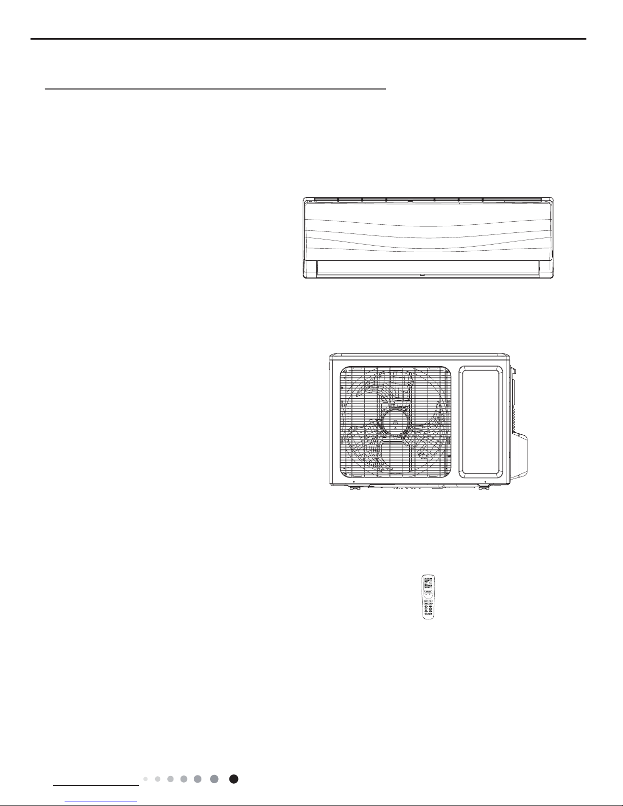
Indoor Unit
GWH09RB-K3DNA3G/I
GWH12RB-K3DNA3G/I
GWH09MB-K3DNE3G/O
GWH12MB-K3DNE3G/O
Outdoor Unit
Remote Controller
YAA1FB
2
Technical Information
Service Manual
2. Specications
2.1 Specication Sheet
Model GWH09RB-K3DNA3G GWH12RB-K3DNA3G
Product Code CB302003100 CB302003200
Power
Supply
Rated Voltage V~ 220-240 220-240
Rated Frequency Hz 50 50
Phases 1 1
Power Supply Mode Outdoor Outdoor
Cooling Capacity W 2600(600~3200) 3500(600~3900)
Heating Capacity W 3000(800~3600) 4000(880~4400)
Cooling Power Input W 870(185~1300) 1170(185~1400)
Heating Power Input W 900(220~1400) 1200(250~1550)
Cooling Power Current A 3.80 5.20
Heating Power Current A 3.92 5.30
Rated Input W 1400 1550
Rated Current A 6.69 7.80
Air Flow Volume(SH/H/M/L/SL) m3/h 600/500/400/300/- 600/500/400/300/-
Dehumidifying Volume L/h 0.8 1.2
EER
W/W 2.99 2.99
COP W/W 3.33 3.33
SEER W/W 6.10 6.10
HSPF W/W 4.00 4.00
Application Area m
2
12-18 16-24
Indoor Unit
Model of indoor unit GWH09RB-K3DNA3G/I GWH12RB-K3DNA3G/I
Indoor Unit Product Code CB302N03100 CB302N03200
Fan Type Cross-ow Cross-ow
Diameter Length(DXL) mm Φ92X645 Φ92X645
Fan Motor Cooling Speed(SH/H/M/L/SL) r/min 1260/1050/950/750/- 1290/1070/900/730/-
Fan Motor Heating Speed(SH/H/M/L/SL) r/min 1320/1150/1050/950/- 1320/1150/1050/920/-
Output of Fan Motor W 20 20
Fan Motor RLA A 0.10 0.10
Fan Motor Capacitor μF 1 1
Evaporator Form Aluminum Fin-copper Tube Aluminum Fin-copper Tube
Pipe Diameter mm Φ7 Φ7
Row-n Gap mm 2-1.4 2-1.4
Coil Length (LXDXW) mm 636X25.4X267 636X25.4X267
Swing Motor Model MP24AA MP24AA
Output of Swing Motor W 2 2
Fuse A 3.15 3.15
Sound Pressure Level (SH/H/M/L/SL) dB (A) 42/39/34/28/- 42/40/35/30/-
Sound Power Level (SH/H/M/L/SL) dB (A) 52/49/44/38/- 52/50/45/40/-
Dimension (WXHXD) mm 848X274X189 848X274X189
Dimension of Carton Box (LXWXH) mm 923X356X264 923X356X264
Dimension of Package (LXWXH) mm 926X359X279 926X359X279
Net Weight kg 10 10
Gross Weight kg 12 12
3
Technical Information
Service Manual
The above data is subject to change without notice; please refer to the nameplate of the unit.
Outdoor Unit
Model of Outdoor Unit GWH09MB-K3DNE3G/O GWH12MB-K3DNE3G/O
Outdoor Unit Product Code CB404W03600 CB404W03500
Compressor Manufacturer/Trademark
ZHUHAI LANDA
COMPRESSOR CO., LTD.
ZHUHAI LANDA
COMPRESSOR CO., LTD.
Compressor Model QXA-A091zE190A QXA-A091zE190A
Compressor Oil RB68EP RB68EP
Compressor Type Rotary Rotary
L.R.A. A 16.5 16.5
Compressor RLA A 4.5 4.5
Compressor Power Input W 942 942
Overload Protector 1NT11L-6233 1NT11L-6233
Throttling Method Electron expansion valve Electron expansion valve
Operation Temp
o
C 16~30 16~30
Ambient Temp (Cooling)
o
C -15~48 -15~48
Ambient Temp (Heating)
o
C -15~24 -15~24
Condenser Form Aluminum Fin-copper Tube Aluminum Fin-copper Tube
Pipe Diameter mm Φ7 Φ7
Rows-n Gap mm 1-1.4 2-1.4
Coil Length (LXDXW) mm 710X19.05X508 695X38.1X506
Fan Motor Speed rpm 900/650 900/650
Output of Fan Motor W 30 30
Fan Motor RLA A 0.15 0.15
Fan Motor Capacitor μF / /
Air Flow Volume of Outdoor Unit m3/h 1600 1600
Fan Type Axial-ow Axial-ow
Fan Diameter mm Φ400 Φ400
Defrosting Method Automatic Defrosting Automatic Defrosting
Climate Type T1 T1
Isolation I I
Moisture Protection IP24 IP24
Permissible Excessive Operating Pressure for
the Discharge Side
MPa 4.3 4.3
Permissible Excessive Operating Pressure for
the Suction Side
MPa 2.5 2.5
Sound Pressure Level (H/M/L) dB (A) 51/-/- 53/-/-
Sound Power Level (H/M/L) dB (A) 61/-/- 63/-/-
Dimension (WXHXD) mm 776X540X320 776X540X320
Dimension of Carton Box (LXWXH) mm 848X360X580 848X360X580
Dimension of Package (LXWXH) mm 851X363X595 851X363X595
Net Weight kg 28 29
Gross Weight kg 31 32
Refrigerant R410A R410A
Refrigerant Charge kg 0.70 0.85
Connection
Pipe
Length m 5 5
Gas Additional Charge g/m 20 20
Outer Diameter Liquid Pipe mm Φ6 Φ6
Outer Diameter Gas Pipe mm Φ9.52 Φ9.52
Max Distance Height m 10 10
Max Distance Length m 15 15
Note: The connection pipe applies metric diameter.
4
Technical Information
Service Manual
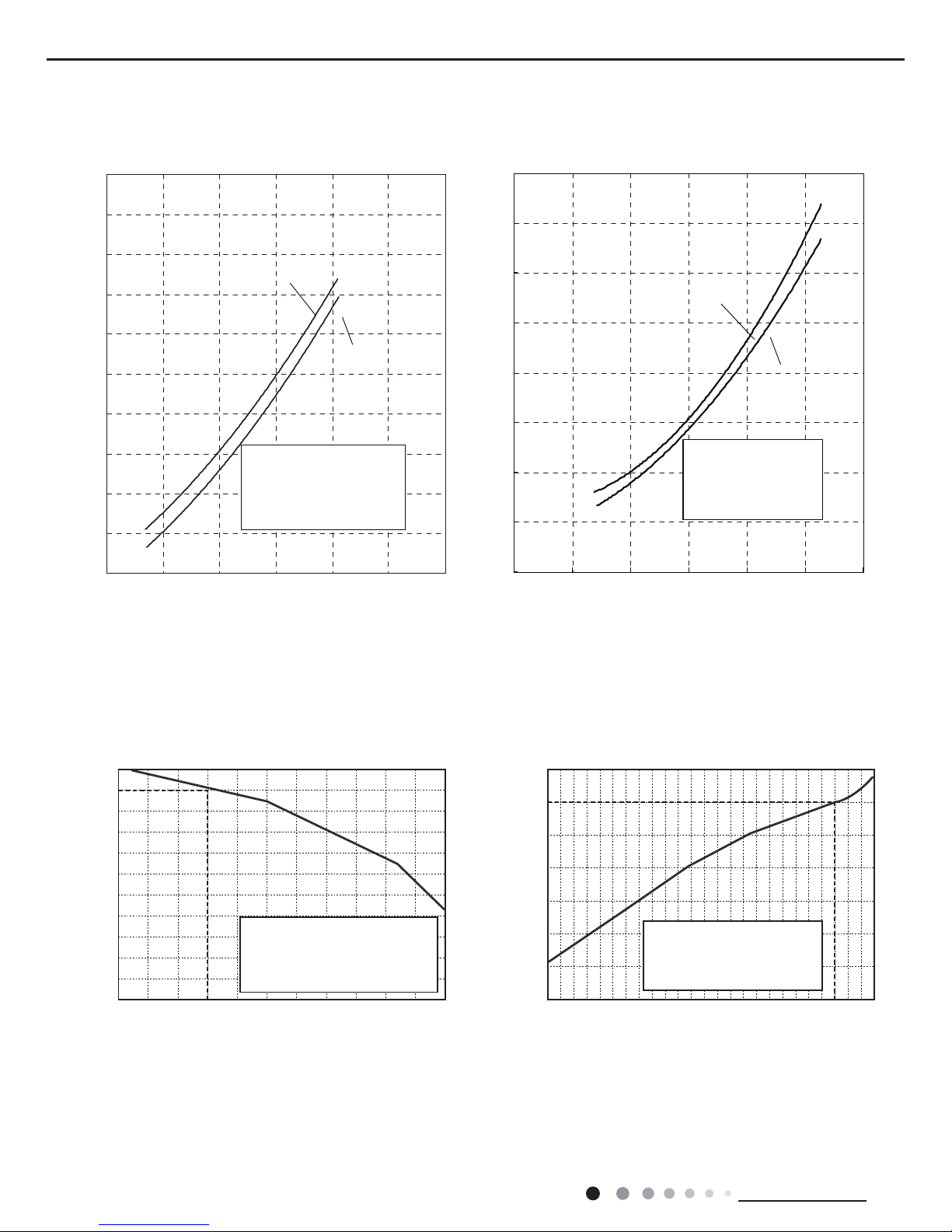
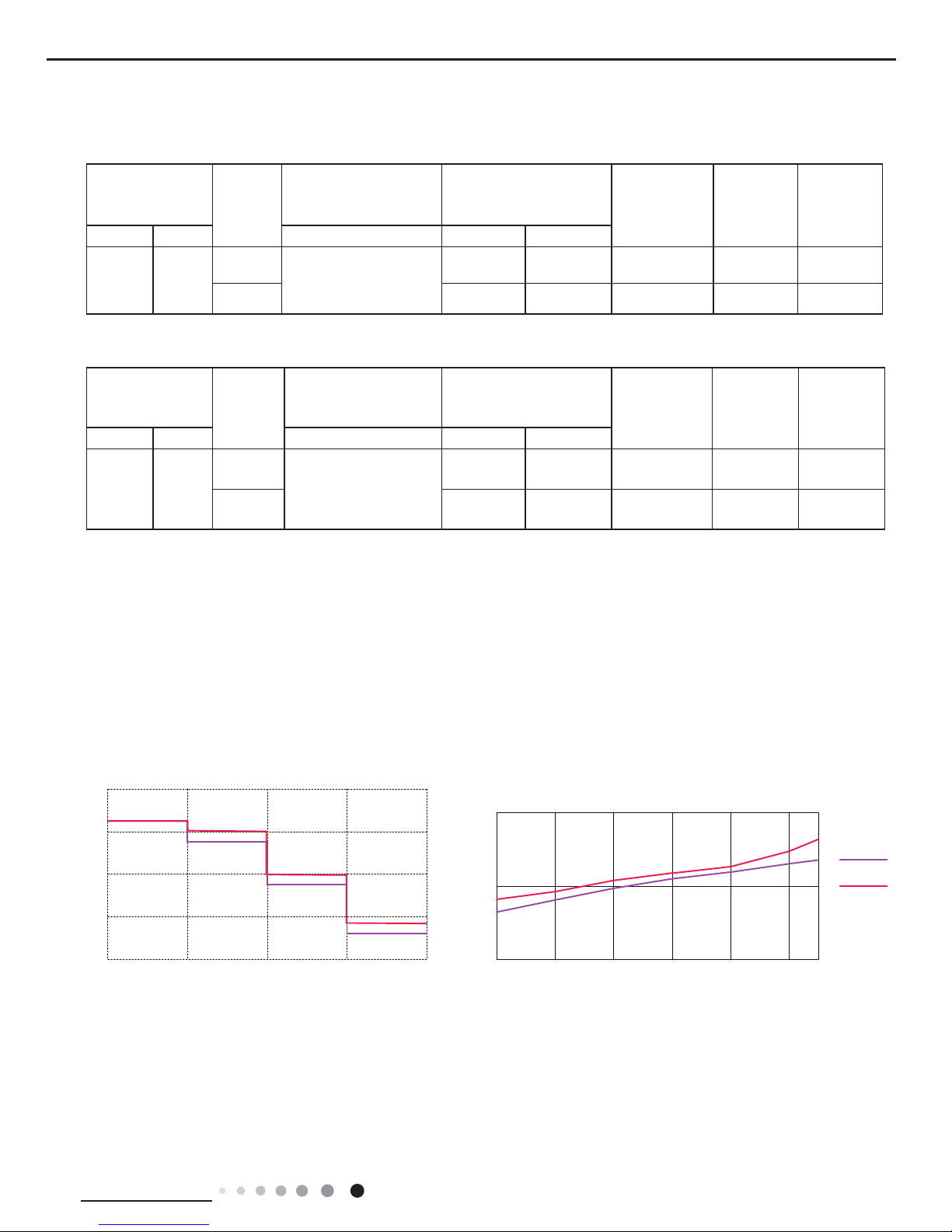
2.2 Operation Characteristic Curve
2.3 Capacity Variation Ratio According to Temperature
Cooling Heating
Cooling Heating
28 30 32 34 36 38 40 42
48
–15 –10 –5
43 44 46
100
105
95
90
85
80
75
70
65
60
55
50
110
100
90
80
70
60
50
40
05
710
Conditions
Indoor:DB27°C/WB19°C
Indoor air flow:Super High
Pipe length: 5m
Conditions
Indoor:DB20°C/WB15°C
Indoor air flow:Super High
Pipe length: 5m
Outdoor temp.(°C) Outdoor temp.(°C)
Capacity ratio (%)
Capacity ratio (%)
Cooling Heating
0
1
2
3
4
5
6
7
8
9
10
020406080100 120
Condition
Indoor:DB 27 WB19
Indoor air flow: Turbo
Pipe length:5m
Voltage:230V
Compressor Speed(rps)
0
1
2
3
4
5
6
7
8
020406080100 12
0
Condition
Indoor:DB 20
Indoor air flow:Turbo
Pipe length:5m
Voltage:230V
Compressor Speed(rps)
Current(A)
Current(A)
09K
12K
°C °C
°C
09K
12K
5
Technical Information
Service Manual
2.4 Cooling and Heating Data Sheet in Rated Frequency
Rated cooling
condition(oC)
(DB/WB)
Model
Pressure of gas pipe
connecting indoor and
outdoor unit
Inlet and outlet pipe
temperature of heat
exchanger
Fan speed of
indoor unit
Fan speed of
outdoor unit
Compressor
frequency
(Hz)
Indoor Outdoor P (MPa) T1 (oC) T2 (oC)
27/19 35/24
09K
0.8 to 1.0
12 to 15 65 to 38 Super High High 54
12K 11 to 14 64 to 37 Super High High 60
Rated heating
condition(oC)
(DB/WB)
Model
Pressure of gas pipe
connecting indoor and
outdoor unit
Inlet and outlet pipe
temperature of heat
exchanger
Fan speed of
indoor unit
Fan speed of
outdoor unit
Compressor
frequency
(Hz)
Indoor Outdoor P (MPa) T1 (oC) T2 (oC)
20/15 7/6
09K
2.2 to 2.4
35 to 63 2 to 5 Super High High 62
12K 35 to 65 2 to 5 Super High High 66
Instruction:
T1: Inlet and outlet pipe temperature of evaporator
T2: Inlet and outlet pipe temperature of condenser
P: Pressure at the side of big valve
Connection pipe length: 5 m.
Cooling:
Heating:
2.5 Noise Curve
Indoor side noise when blowing
Outdoor side noise when Compressor speed changed
CompressorSpeed(rps)
706050403020
45
50
55
)A(Bd/esioN
75
09K
12K
Indoor fanmotor rotating speed
LowMiddleHighSupper High
25
30
35
40
45
)A(Bd/esioN
6
Technical Information
Service Manual
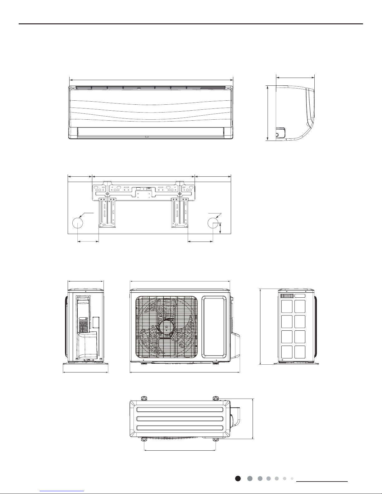
3. Outline Dimension Diagram
3.1 Indoor Unit
3.2 Outoor Unit
Unit:mm
Unit:mm
320
776
510
714257
286
540
274
189
50
85
174542132
69
Φ55
Φ55
848
7
Technical Information
Service Manual
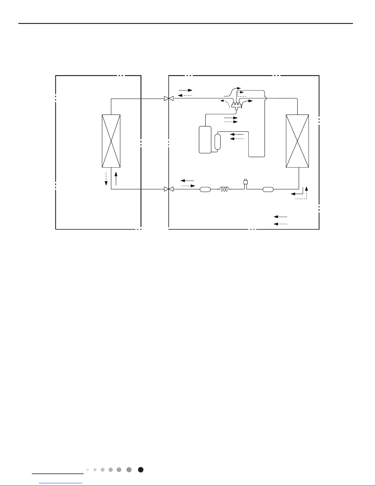
4. Refrigerant System Diagram
Connection pipe specication:
Liquid pipe:1/4" (6mm)
Gas pipe:3/8" (9.52mm)
Indoor unit
Outdoor unit
COOLING
HEATING
Accumlator
4-Way valve
Discharge
Suction
Heat
exchanger
(evaporator)
Heat
exchanger
(condenser)
Valve
Valve
Liquid pipe
side
Gas pipe
side
StrainerStrainer ElectronCapillary
expansion
valve
Compressor
8
Technical Information
Service Manual
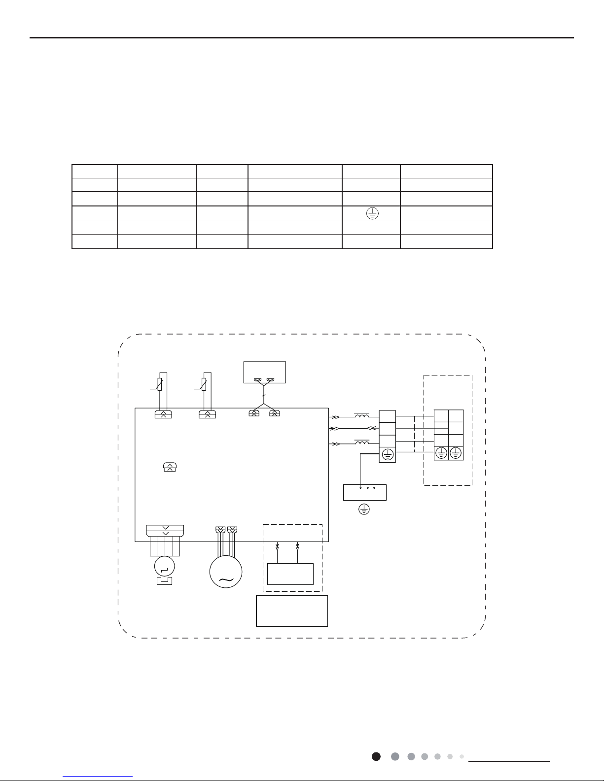
5. Electrical Part
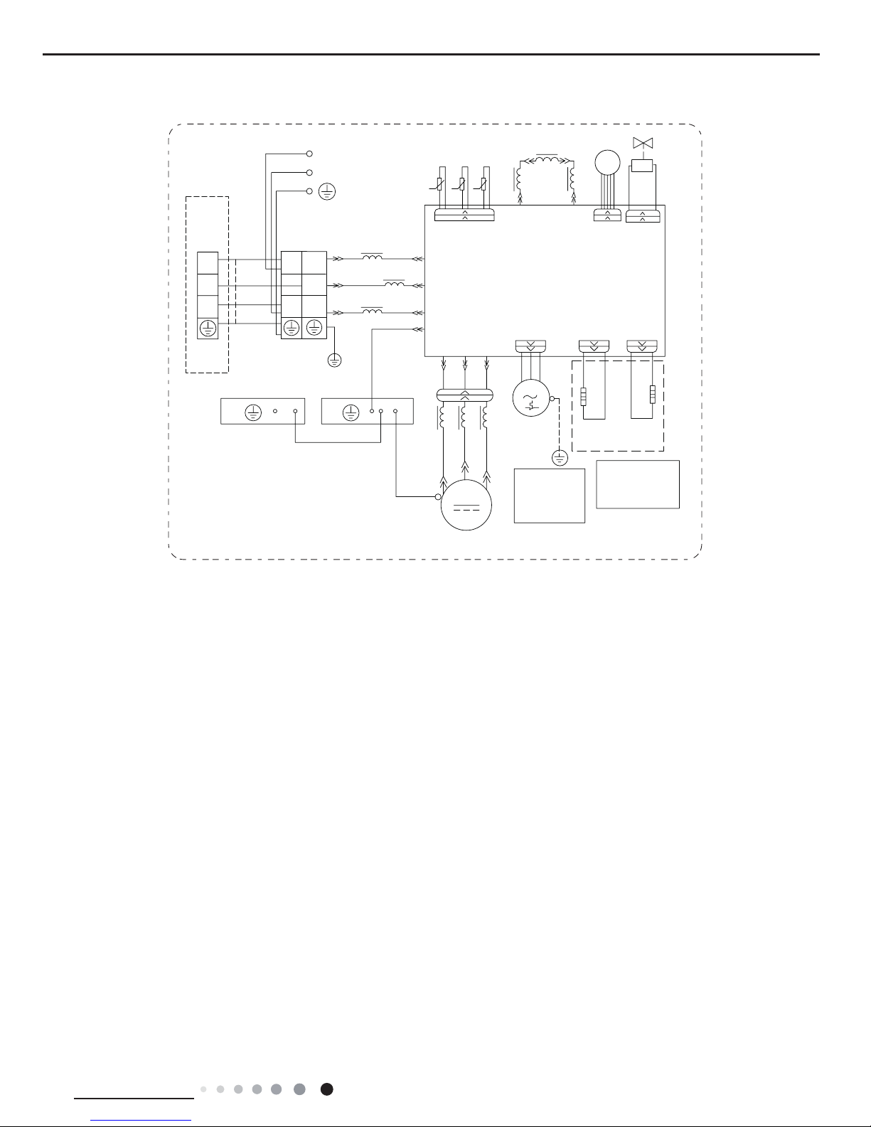
5.1 Wiring Diagram
● Indoor Unit
●Instruction
Symbol Symbol Color Symbol Symbol Color Symbol Name
WH White GN Green CAP Jumper cap
YE Yellow BN Brown COMP Compressor
RD Red BU Blue Grounding wire
YEGN Yellow/Green BK Black / /
VT Violet OG Orange / /
Note: Jumper cap is used to determine fan speed and the swing angle of horizontal lover for this model.
%/2&.
7(50,1$/
;7
1
$3
;7
%8
%1
1
&20287
<(*1
1
%.
(9$325$725
5' %8
+($/7+1+($/7+/
%8
%.
%1
<(*1
81,7
287'225
1
/
/
/
57
57
-803
&$3
7(06(1625
5220
78%(
7(06(1625
)$1027256:,1*027258'
6:,1*8'
78%(5220
$&/
3*
3*)
',63/$<
$3
',63
',63
0
0
3(
*(1(5$725
&22/3/$60$
&22/3/$60$
*(1(5$725,6
237,21$/
Њ
9
Technical Information
Service Manual
These circuit diagrams are subject to change without notice, please refer to the one supplied with the unit.
● Outdoor Unit
3(
32:(5
3(
/
1
/
1
1
;7
/
:+
2*
/
(
:
9
8
/;
/;
2)$1
:98
&208
1
$&/
0,',62/$7,216+((7
%2;
/
3(
%8
%.
%1
5'
<(%8
<(*1
5'
<(
%8
&203
)$102725
<(*1
<(*1
<(*1
/
/
$3
3(
3(
0
&203
/
(/(&75,&
+($7
(+
+($7(5
&+$66,6
+($7
&203
+($7(5
5'5'
(+
5'5'
:$<
<9
©
©
©
7(06(1625
(;+$867
2875220
7(06(1625
&1
57
57
57
7(06(1625
78%(
/
;7
,1'225
81,7
7(50,1$/
%/2&.
%8
%.
%1
<(*1
<(*1
NOTE:
Motor
applies to the
iron shell motor.
ground only
&1
(.9
The electrical
heaters are
optional.
1
10
Technical Information
Service Manual
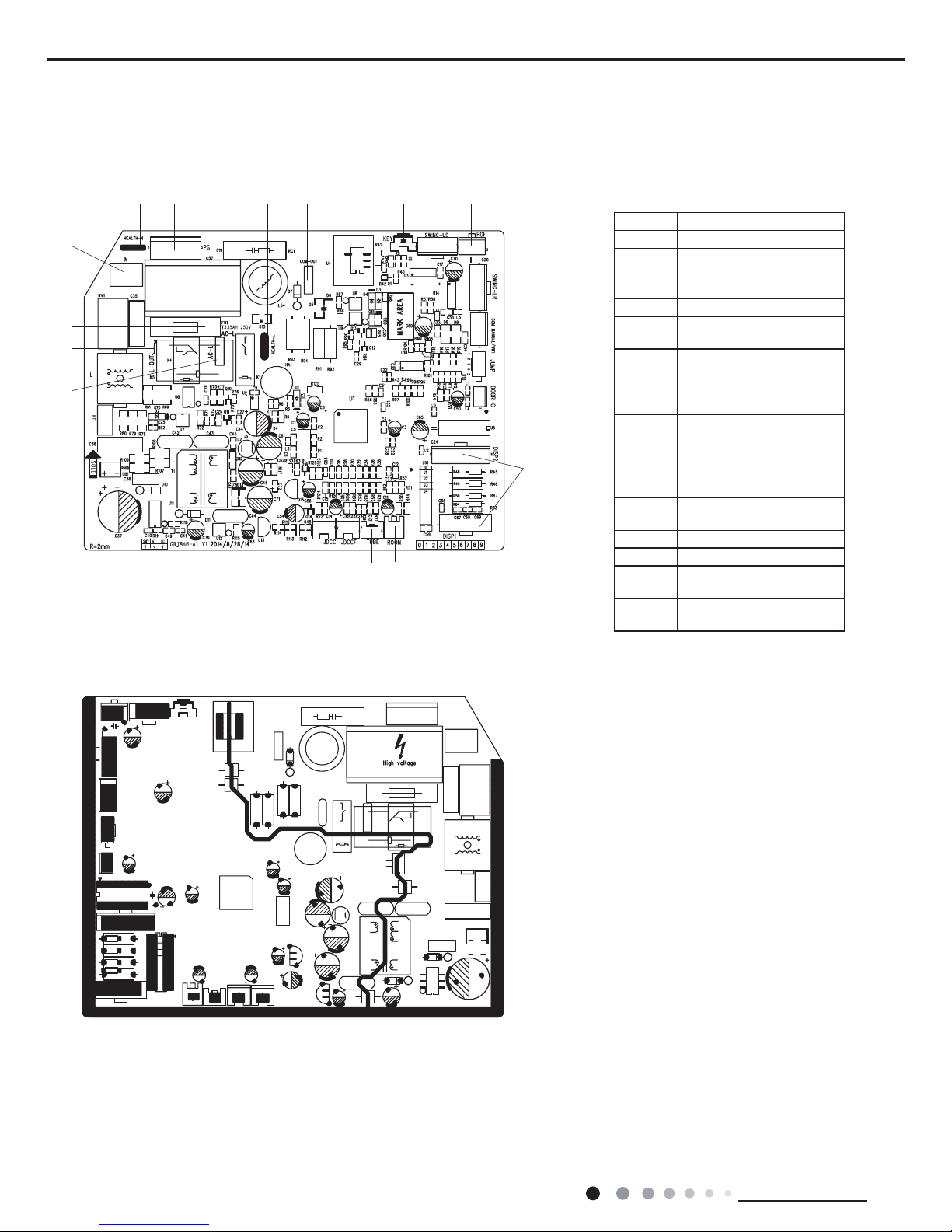
5.2 PCB Printed Diagram
● Top view
Indoor Unit
● Bottom view
No. Name
1 Interface of live wire
2
Interface of live wire for
outdoor control
3 Fuse
4 Interface of neutral wire
5
Interface of neutral wire for
health function
6
Control interface of PG
motor
7
Interface of live wire for
health function
8
Interface of indoor
unit and outdoor unit
communication
9 Auto button
10 Up & down swing
11
Feedback interface of
indoor fan
12 Jump
13 Interface of display
14
Ambient temperature
sensor interface
15
Indoor tube temperature
sensor interface
1
2
3
4
5 6 7 8 9 10 11
12
13
1415
11
Technical Information
Service Manual
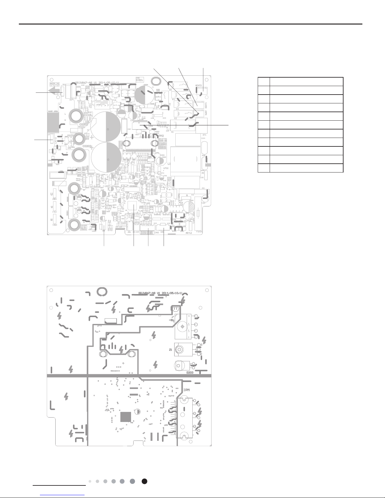
● Top view
Outdoor Unit
● Bottom view
No. Name
1
Inductance pin2
2
Inductance pin1
3
Four-wayvalve
4
Compressor electric heater
5
Chassis electric heater
6
Fan neilsbed
7
Electric expansion valve
8
Temp. sensor
9
Main chip
10
EEPROM
1
2
345
6
78910
12
Technical Information
Service Manual
6. Function and Control
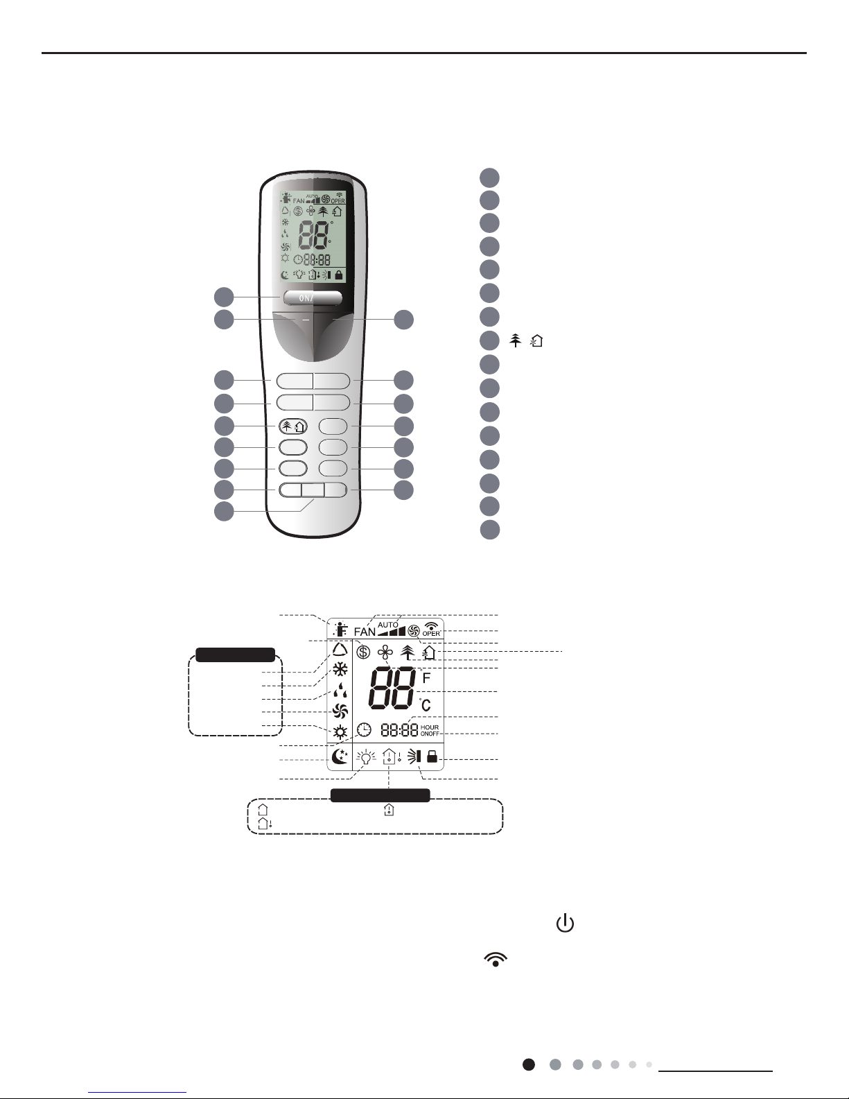
6.1 Remote Controller Introduction
Buttons on Remote Controller
Introduction for Icons on Display Screen
Introduction for Buttons on Remote Controller
1
1
2
5
4
6
7
8
11
12
13
9
14
15
ON/OFF button
- button
3
SWING button
FAN button
MODE button
I FEEL button
CLOCK button
10
TIMER-ON button
TIMER-OFF button
TURBO button
LIGHT button
16
X-FAN button
SLEEP button
TEMP button
button
/
+ button
21 2))/
02'( )$1
6:,1*,)((/
6/((3
7(03
7,0(521
&/2&.
72)),0(5
785%2 /,*+7;)$1
F
C
HOUR
ONOFF
2
3
4
5
6
7
8
9
10
11
12
13
14
16
15
Send signal
Turbo mode
8ć heating function
Set temperature
Set time
TIMER ON /
TIMER OFF
Child lock
Up & down swing
Set fan speed
ventilation operation
Light
Temp. display type
:Set temp.
:Outdoor ambient temp.
:Indoor ambient temp.
Sleep mode
Clock
Heat mode
Fan mode
Dry mode
Cool mode
Auto mode
Operation mode
I feel
1
1
2
5
4
6
7
8
11
12
13
9
14
15
ON/OFF button
- button
3
SWING button
FAN button
MODE button
I FEEL button
CLOCK button
10
TIMER-ON button
TIMER-OFF button
TURBO button
LIGHT button
16
X-FAN button
SLEEP button
TEMP button
button
/
+ button
X-fan mode
health function
21 2))/
02'( )$1
6:,1*,)((/
6/((3
7(03
7,0(521
&/2&.
72)),0(5
785%2 /,*+7;)$1
F
C
HOUR
ONOFF
2
3
4
5
6
7
8
9
10
11
12
13
14
16
15
Note:
● After putting through the power, the air conditioner will give out a sound. Operation indictor " " is ON (red indicator). After that, you
can operate the air conditioner by using remote controller.
● Under on status, pressing the button on the remote controller, the signal icon " "on the display of remote controller will blink once
and the air conditioner will give out a “de” sound, which means the signal has been sent to the air conditioner.
● Under off status, set temperature and clock icon will be displayed on the display of remote controller (If timer on, timer off and light
functions are set, the corresponding icons will be displayed on the display of remote controller at the same time); Under on status, the
display will show the corresponding set function icons.
1. ON/OFF Button
13
Technical Information
Service Manual
Press this button to turn on the unit. Press this button again to turn off the unit.
2. - Button
Press this button to decrease set temperature. Holding it down above 2 seconds rapidly decreases set temperature. In AUTO mode, set
temperature is not adjustable.
3. + Button
Press this button to increase set temperature. Holding it down above 2 seconds rapidly increases set temperature. In AUTO mode, set
temperature is not adjustable.
4. MODE Button
Each time you press this button, a mode is selected in a sequence that goes from AUTO, COOL, DRY, FAN, and HEAT*, as the following:
*Note:Only for models with heating function.
After energization, AUTO mode is defaulted. In AUTO mode, the set temperature will not be displayed on the LCD, and the unit will
automatically select the suitable operation mode in accordance with the room temperature to make indoor room comfortable.
(As for cooling only unit, it won’t have any action when it receives the signal of heating operation.)
5. FAN Button
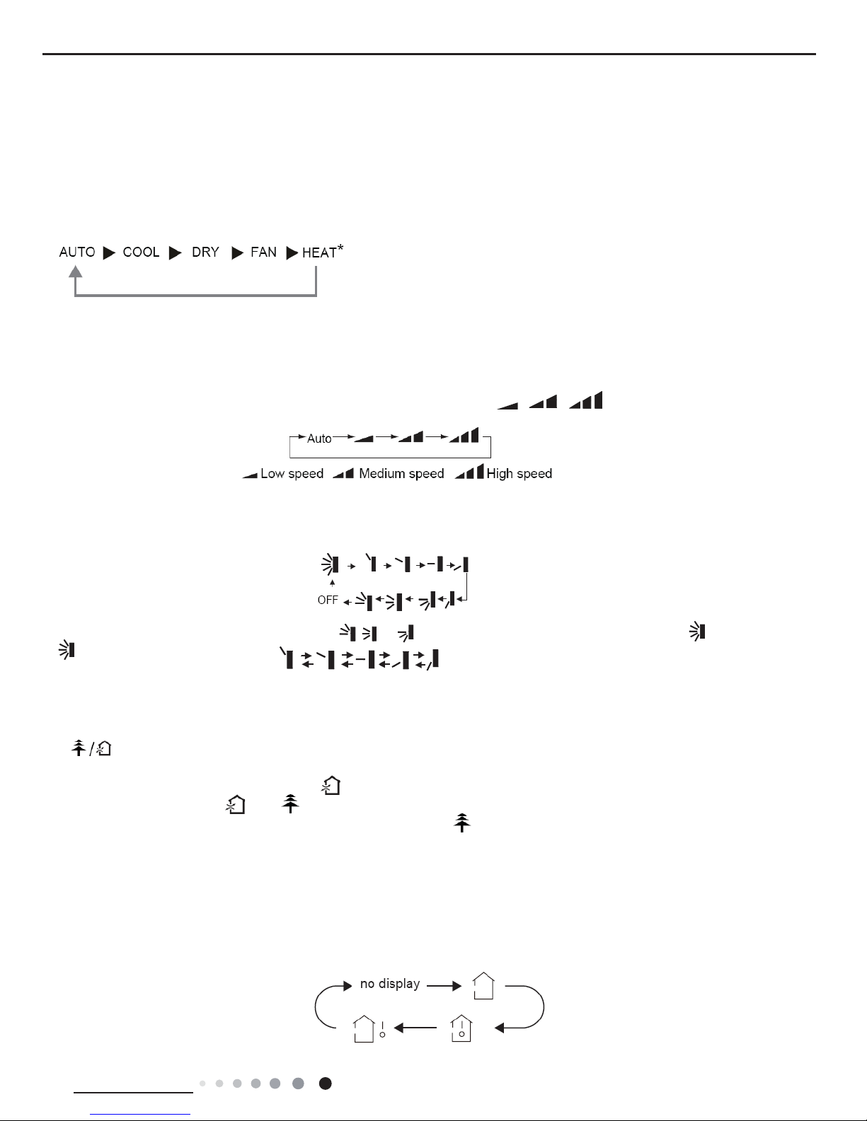
This button is used for setting Fan Speed in the sequence that goes from AUTO, , to , then back to Auto.
6. SWING Button
Press this button to set up &down swing angle, which circularly changes as below:
This remote controller is universal. If any command , or is sent out, the unit will carry out the command as
indicates the guide louver swings as:
7. I FEEL Button
Press this button to turn on I FEEL function. The unit automatically adjust temperature according to the sensed temperature. Press this
button again to cancel I FEEL function.
8. Button
Press this button to achieve the on and off of healthy and scavenging functions in operation status. Press this button for the rst
time to start scavenging function; LCD displays " ". Press the button for the second time to start healthy and scavenging functions
simultaneously; LCD displays " " and " ". Press this button for the third time to quit healthy and scavenging functions simultaneously.
Press the button for the fourth time to start healthy function; LCD display " ". Press this button again to repeat the operation above. (This
function is applicable to partial of models)
9. SLEEP Button
Press this button to go into the SLEEP operation mode. Press it again to cancel this function. This function is available in COOL, HEAT
(Only for models with heating function) or DRY mode to maintain the most comfortable temperature for you.
10. TEMP Button
Press this button can see indoor set temperature, indoor ambient temperature or outdoor ambient temperature on indoor unit’s display.
Temperature is set circularly by remote controller as below:
14
Technical Information
Service Manual
● When selecting " " by remote controller or no display, temperature indicator on indoor unit displays set temperature.
● When selecting " " by remote controller, temperature indicator on indoor unit displays indoor ambient temperature.
● When selecting " " by remote controller, temperature indicator on indoor unit displays outdoor ambient temperature.
11. TIMER-ON Button
Press this button to initiate the auto-ON timer. To cancel the auto-timer program, simply press this button again.
After press of this button, disappears and "ON" blinks. 00:00 is displayed for ON time setting. Within 5 seconds, press + or - button to
adjust the time value. Every press of either button changes the time setting by 1 minute. Holding down either button rapidly changes the
time setting by 1 minute and then 10 minutes. Within 5 Seconds after setting,press TIMER ON button to conrm.
12. CLOCK Button
Press CLOCK button,blinking. Within 5 seconds, pressing + or - button adjusts the present time. Holding down either button above 2
seconds increases or decreases the time by 1 minute every 0.5 second and then by 10 minutes every 0.5 second. During blinking after
setting, press CLOCK button again to conrm the setting, and then will be constantly displayed.
13. TIMER-OFF Button
Press this button to initiate the auto-off timer. To cancel the auto-timer program, simply press the button again. TIMER OFF setting is the
same as TIMER ON.
14. TURBO Button
Press this button to activate / deactivate the Turbo function which enables the unit to reach the preset temperature in the shortest time.
In COOL mode, the unit will blow strong cooling air at super high fan speed. In HEAT mode, the unit will blow strong heating air at super
high fan speed.
15. LIGHT Button
Press LIGHT button to turn on the display's light and press this button again to turn off the display's light. If the light is turned on, is
displayed. If the light is turned off, disappears.
16. X-FAN Button
Pressing X-FAN button in COOL or DRY mode, the icon is displayed and the indoor fan will continue operation for 10 minutes in order
to dry the indoor unit even though you have turned off the unit.
After energization, X-FAN OFF is defaulted. X-FAN is not available in AUTO, FAN or HEAT mode.
17. Combination of "+" and "-" buttons: About lock
Press "+" and "-" buttons simultaneously to lock or unlock the keypad. If the remote controller is locked, is displayed. In this case,
pressing any button, blinks three times.
18. Combination of "MODE" and "-" buttons:About switch between Fahrenheit and centigrade
At unit OFF, press "MODE" and "-" buttons simultaneously to switch between °C and °F.
19. Combination of "TEMP" and "CLOCK" buttons:About Energy-saving Function
Press "TEMP" and "CLOCK" simultaneously in COOL mode to start energy-saving function.Nixie tube on the remote controller displays
"SE". Repeat the operation to quit the function.
20. Combination of "TEMP" and "CLOCK" buttons:About 8°C Heating Function
Press "TEMP" and "CLOCK" simultaneously in HEAT mode to start 8°C Heating Function Nixie tube on the remote controller displays
" " and a selected temperature of "8°C".(46°F if Fahrenheit is adopted). Repeat the operation to quit the function.
21. About Back-lighting Function
The unit lights for 4s when energizing for the rst time, and 3s for later press.
22. About HEALTH function (COLD PLASMA)
Turn on the unit, start up the fan (Breezing and X-FAN are excluded) and press HEATLTH button on remote controller to start health
function (If there is not HEALTH button on remote controller, the unit defaults health function ON.)
23. Operation guide
1. After putting through the power, press "ON/OFF" button on remote controller to turn on the air conditioner.
2. Press "MODE" button to select your required mode: AUTO, COOL, DRY, FAN,HEAT.
3. Press "+" or "-" button to set your required temperature. (Temperature can’t be adjusted under auto mode).
4. Press "FAN" button to set your required fan speed: auto, low, medium and high speed.
5. Press "SWING" button to select fan blowing angle.
15
Technical Information
Service Manual
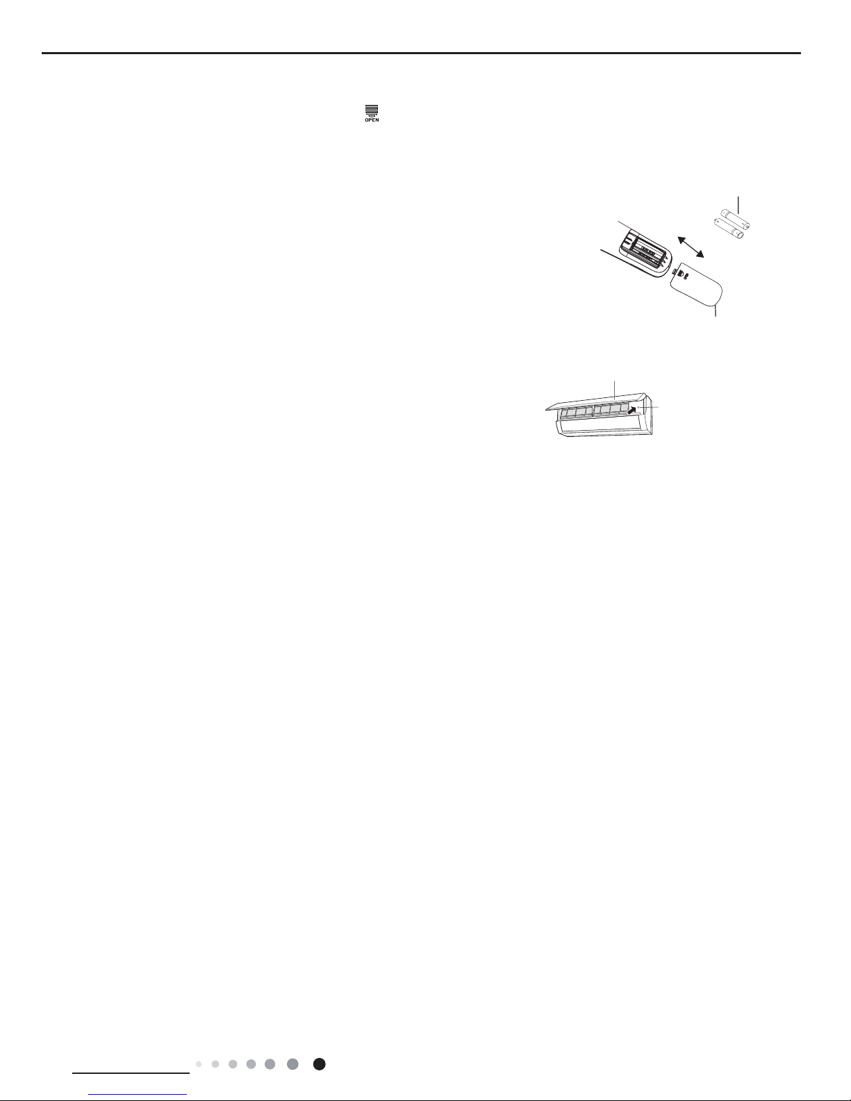
If remote controller is lost or damaged, please use auxiliary button to turn on or turn
off the air conditioner. The operation in details are as below: As shown in the g.
Open panel, press aux. button to turn on or turn off the air conditioner. When the air
conditioner is turned on, it will operate under auto mode.
Emergency Operation
Emergency operation
switch
Panel
Note:
● During operation, point the remote control signal sender at the receiving window
on indoor unit.
● The distance between signal sender and receiving window should be no more than
8m, and there should be no obstacles between them.
● Signal may be interfered easily in the room where there is fluorescent lamp or
wireless telephone; remote controller should be close to indoor unit during operation.
● Replace new batteries of the same model when replacement is required.
● When you don’t use remote controller for a long time, please take out the batteries.
● If the display on remote controller is fuzzy or there’s no display, please replace
batteries.
1.Press the back side of remote controller marked with“ ”as shown in the g, and then push out the cover
of battery box along the arrow direction.
2. Replace two 7# (AAA 1.5V) dry batteries, and make sure the position of “+” polar and “-“ polar are correct.
3. Reinstall the cover of battery box.
Replacement of Batteries in Remote Controller
battery
Cover of battery box
remove
reinstall
16
Technical Information
Service Manual
6.2 Brief Description of Modes and Functions
1. Temperature Parameters
◆
Indoor preset temperature (T
preset
)
◆
Indoor ambient temperature (T
amb.
)
2. Basic Functions
Once energized, in no case should the compressor be restarted within less than 3 minutes. In the situation that memory function is
available, for the rst energization, if the compressor is at stop before de-energization, the compressor will be started without a 3-minute
lag; if the compressor is in operation before de-energization, the compressor will be started with a 3-minute lag; and once started, the
compressor will not be stopped within 6 minutes regardless of changes in room temperature;
(1)COOL Mode
①
The condition and process of cooling
If T
amb.≥Tpreset
COOL mode will act, the compressor and outdoor fan will run, and the indoor fan will run at the set speed.
If T
amb
.≤T
preset
-2°C,the compressor will stop, the outdoor fan will delay 30 seconds to stop, and the indoor fan will run at the set speed.
If T
preset
-2°C≤T
amb.≤Tpreset
,the unit will keep running in the previous mode.
In this mode, the reversal valve will not be powered on and the temperature setting range is 16~30°C.
②
Protection function
◆
Overcurrent protection
If total current is high, the compressor will run in limited frequency. If total current is too high, the compressor will stop, the outdoor fan
will delay 30 seconds to stop, indoor unit will display E5 and outdoor yellow light will blink 5 times.
◆
Antifreezing protection
When the antifreezing protection is detected, the compressor will stop, the outdoor fan will stop after 30 seconds, and the indoor fan and
swing motor will keep running in the original mode. When antifreezing protection is eliminated and the compressor has stopped for 3
minutes, the compressor will resume running in the original mode.
(2)Dehumidifying Mode
①
Working conditions and process of dehumidifying
If T
amb.>Tpreset,
the unit will enter cooling and dehumidifying mode, in which case the compressor and the outdoor fan will operate and the
indoor fan will run at low speed.
If T
preset
-2°C≤T
amb.≤Tpreset
, the compressor remains at its original operation state.
If T
amb.<Tpreset
-2°C, the compressor will stop, the outdoor fan will stop with a time lag of 30s, and the indoor fan will operate at low speed.
②
Protection
Protection is the same as that under the cooling mode.
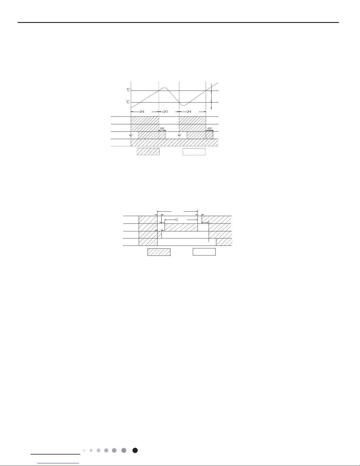
(3) HEAT Mode
①
The condition and process of heating
If T
amb≤Tpreset
+2°C , HEAT mode will act, the compressor, outdoor fan and reversal valve will run, the indoor fan will delay 3min to stop at
the latest.
If T
preset
+2°C<T
amb
< T
preset
+5°C ,the unit will keep running in the original mode.
If T
amb.≥Tpreset
+5°C , the compressor will stop, the outdoor fan will delay 30sec to stop and indoor fan will blow 60S at low speed, the fan
speed cannot be shifted within blow residual heat.
◆
In this mode, the temperature setting range is 16~30°C.
◆
The air conditioner will adjust the running frequency of the compressor automatically according to the change of ambient temperature.
◆
When the unit is turned off in HEAT mode, or switched to other mode from HEAT mode, the four-way valve will be powered off after
During antifreeze protection
Compressor
Outdoor fan
Indoor fan
min
Preset speed
Ru
nS
top
Run
Tamb.
Stop
Stop cooling
Start cooling
Original operating status
≥ 6 min. ≥ 3 min. ≥ 6 min.
Setting fan speed
Tpreset
Tpreset –2 ˚C
Compressor
Outdoor fan
Indoor fan
Run
Tamb.
Stop
Stop cooling
Start cooling
Original operating status
≥ 6 min. ≥ 3 min. ≥ 6 min.
Setting fan speed
17
Technical Information
Service Manual
the compressor stops.
◆
When compressor is running (not including each malfunction and protection):
a.When outdoor ambient temperature≥20°C and indoor fan speed is low or medium, the fan speed will turn to high; if indoor fan speed
is high or super high, it will keep the same.
b.When outdoor ambient temperature≤18°C, the fan speed will resume set fan speed.
c. When 18°C<outdoor ambient temperature<20°C, it will run at present fan speed (set fan speed or high fan speed); but when rst
exiting cold air prevention after entering heating mode, it will run in set fan speed.
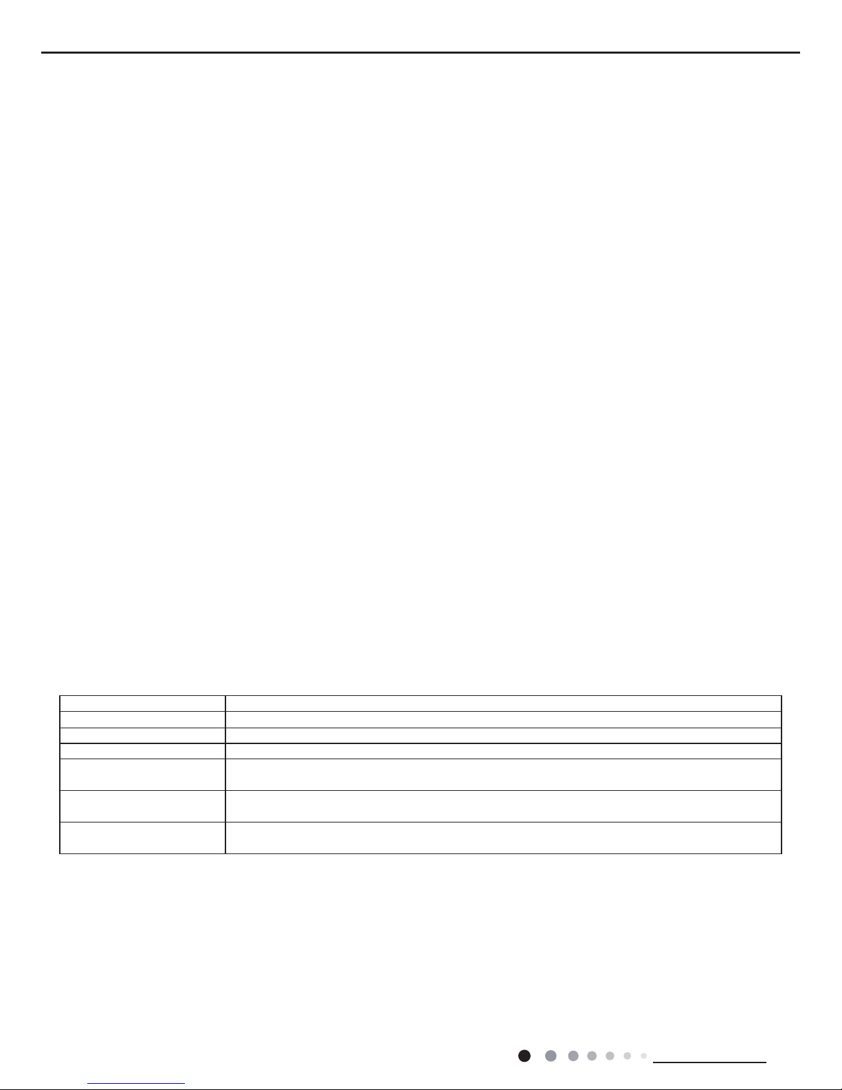
②
The condition and process of defrosting
When frost is detected in the condenser, the system will enter into defrosting state. When defrosting starts, the compressor and indoor
fan will stop, and the outdoor fan and four-way valve will delay 30 seconds to stop. The compressor will start after 15 seconds and
then defrosting will be started. When the compressor has run for 7 minutes or defrosting is nished, the compressor will stop. After 30
seconds the four-way valve opens and after another 60 seconds, the compressor and outdoor fan resume running. Theindoor fan will
delay 3 minutes to run at the latest .The Heat indicator will be off for 0.5 second in each 10 seconds during defrosting.
③
Protection function
◆
Anti-cold-wind protection
In HEAT mode, in order to prevent the indoor unit from blowing out cold wind, each time the compressor starts, the indoor fan will delay
3 minutes after the compressor to run at the latest and it can adjust fan speed automatically when temperature is low.
◆
Cold air prevention
The unit is started under heating mode (the compressor is ON):
①
In the case of T
indoor amb.
<24°C: if T
tube
≤40°C and the indoor fan is at stop state, the indoor fan will begin to run at low speed with a time
lag of 2 minutes. Within 2 minutes, if T
tube
>40°C, the indoor fan also will run at low speed; and after1-minute operation at low speed, the
indoor fan will be converted tooperation at preset speed. Within 1-minute low speed operation or 2-minute non-operation, if T
tube
≤42°C,
the fan will run at present speed.
②
In the case of T
indoor amb.
≥24°C: if T
tube
≤42°C, the indoor fan will run at low speed, and afterone minute, the indoorfan will be converted
to preset speed. Within one-minute low speed operation, if T
tube
>42°C, the indoor fan will beconvertedto preset speed.
Note: T indoor amb. indicated in ① and ② refers to, under initially heating mode, the indoor ambient temperature before the command
to start the compressor is performed according to the program, or after the unit is withdrawn from defrost, the indoor ambient
temperature before the defrost symbol is cleared.
◆
Total current up and frequency down protection
If the total current I
total
≤W, frequency rise will be allowed; if I
total
≥X, frequency rise will not be allowed; if I
total
≥Y, the compressor will run at
reduced frequency; and if I
total
≥Z, the compressor will stop and the outdoor fan will stop with a time lag of 30s.
(4) Fan Mode
Under the mode, the indoor fan will run at preset speed and the compressor, the outdoor fan, the four-way valve and the electric heater
will stop.
Under the mode, temperature can be set within a range of 16~30°C.
(5) AUTO Mode
①
Operation way of AUTO mode
a.When T
ambient
≥26°C, it will run in cooling mode. The implied set temperature is 25°C (note: the set temperature sending to outdoor unit
is 25°C).
b.For heating and cooling unit, when T
ambient
≤(19°C+T
supplementary
), it will run in heating mode. The implied set temperature is 20°C; for
cooling only unit, when T
ambient
≤22°C, it will run in fan mode and the displayed set temperature is 25°C.
T
preset
+5
T
preset
+2
Stop heating
Original operating status
Start heating
Run
Indoor fan
valve
Outdoor fan
Compressor
Stop
min.
min.
min.
T
amb
.
.nim.nim
preset wind
preset wind
Reversing
The period of defrosting
Four-way
valve
Compressor
Outdoor Unit
30s
30s
15s
30s
60s
Indoor Unit
7min
3min
Setfan speed
Run Stop
T
preset
+5
T
preset
+2
Stop heating
Original operating status
Start heating
Run
Indoor fan
valve
Outdoor fan
Compressor
Stop
min.
min.
min.
T
amb
.
.nim.nim
preset wind
preset wind
Reversing
18
Technical Information
Service Manual
c.For heating and cooling unit, when (19°C+T
supplementary
)<T
indoor ambient
<
26°C (for cooling only unit, 22°C<T
indoor ambient
<
26°C), it will
keep the original running mode. If the unit is energized for the rst time, it will run in fan mode.
②
Protection
a. In cooling operation, protection is the sam e as that under the cooling mode;
b. In heating operation, protection is the same as that under the heating mode;
c. When ambient temperature changes, operation mode will be converted preferentially. Once started, the compressor will remain
unchanged for at least 6 minutes.
(6) Common Protection Functions and Fault Display under COOL, HEAT, DRY and AUTO Modes
①
Overload protection
Ttube: measured temperature of outdoor heat exchanger under cooling mode; and measured temperature of indoor heat exchanger
under heating mode.
1) Cooling overload
a.If T
tube
≤52°C, the unit will return to its original operation state.
b.If T
tube
≥55°C, frequency rise is not allowed.
c.If T
tube
≥58°C, the compressor will run at reduced frequency.
d.If T
tube
≥62°C, the compressor will stop and the indoor fan will run at preset speed.
2) Heating overload
a.If T
tube
≤50°C, the unit will return to its original operation state.
b.If T
tube
≥53°C, frequency rise is not allowed.
c.If T
tube
≥56°C, the compressor will run at reduced frequency.
d.If T
tube
≥60°C, the compressor will stop and the indoor fan will blow residue heat and then stop.
②
Exhaust temperature protection of compressor
If exhaust temperature≥98°C, frequency is not allowed to rise.
If exhaust temperature≥103°C, the compressor will run at reduced frequency.
If exhaust temperature≥110°C, the compressor will stop.
If exhaust temperature≤90°C and the compressor has stayed at stop for at least 3 minutes, the compressor will resume its operation.
③
Communication fault
If the unit fails to receive correct signals for durative 3 minutes, communication fault can be justied and the whole system will stop.
④
Module protection
Under module protection mode, the compressor will stop. When the compressor remains at stop for at least 3 minutes, the compressor
will resume its operation. If module protection occurs six times in succession, the compressor will not be started again.
⑤
Overload protection
If temperature sensed by the overload sensor is over 115°C, the compressor will stop and the outdoor fan will stop with a time lag of 30
seconds. If temperature is below 95°C, the overload protection will be relieved.
⑥
If voltage on the DC bus is below 150V or over 420V, the compressor will stop and the outdoor fan will stop with a time lag of 30
seconds. When voltage on the DC bus returns to its normal value and the compressor has stayed at stop for at least 3 minutes, the
compressor will resume its operation.
⑦
Faults of temperature sensors
Designation of sensors Faults
Indoor ambient temperature The sensor is detected to be open-circuited or short-circuited for successive 5 seconds
Indoor tube temperature The sensor is detected to be open-circuited or short-circuited for successive 5 seconds
Outdoor ambient temperature The sensor is detected to be open-circuited or short-circuited for successive 30 seconds
Outdoor tube temperature
The sensor is detected to be open-circuited or short-circuited for successive 30 seconds, and no
detection is performed within 10 minutes after defrost begins.
Exhaust
After the compressor has operated for 3 minutes, the sensor is detected to be open-circuited or shortcircuited for successive 30 seconds.
Overload
After the compressor has operated for 3 minutes, the sensor is detected to be open-circuited or shortcircuited for successive 30 seconds.
3. Other Controls
(1) ON/OFF
Press the remote button ON/OFF: the on-off state will be changed once each time you press the button.
(2) Mode Selection
Press the remote button MODE, then select and show in the following ways: AUTO, COOL, DRY, FAN, HEAT, AUTO.
(3) Temperature Setting Option Button
Each time you press the remote button TEMP+ or TEMP-, the setting temperature will be up or down by 1. Regulating Range: 16~30°C,
the button is useless under the AUTO mode.
(4) Time Switch
You should start and stop the machine according to the setting time by remote control.
19
Technical Information
Service Manual
(5) SLEEP State Control
a. When the air conditioner is under the mode of COOL, and the SLEEP mode has been set well, after the SLEEP state keeps about 1
hour, the pre-setting T will raise 1°C, and it will raise 1°C again after 2 hours, so it raise 2°C in 2 hours, then it will run on at the setting
temperature and wind speed.
b. When the air conditioner is under the mode of HEAT, and the Timer has been set well, after the SLEEP state keeps about 1 hour,
the pre-setting T will reduce 1°C, and it will reduce 1°C again after 2 hours, so it reduce 2°C in 2 hours, then it will run on at the setting
temperature and wind speed.
c. The setting temperature keeps the same under the FAN mode and AUTO mode.
(6) Indoor Fan Control
Indoor fan could be set at ultra-high, high, medium, low speed by wireless remote controller and operated as that speed.
Auto fan speed could be set as well, indoor fan will operate under auto fan speed as following:
①
Under heating mode: auto speed under heating or auto heating mode:
a. When T
amb.≤Tpreset
+1°C, indoor fan will operate at high speed;
b. When T
preset
+1°C<T
amb.
<
T
preset
+3°C, indoor fan will operate at medium speed;
c. When T
amb.≥Tpreset
+3°C, indoor fan will operate at low speed;
There should be at least 180s operation time during switchover of each speed.
②
Under cooling mode: auto speed under cooling or auto cooling mode:
a. When T
amb.
<
T
preset
+2°C, indoor fan will operate at high speed;
b. When T
preset
<
T
amb.
<
T
preset
+2°C, indoor fan will operate at medium speed;
c. When T
amb.≤Tpreset
, indoor fan will operate at low speed;
There should be at least 180s operation time during switchover of each speed.
(7) Buzzer Control
The buzzer will send a “Di” sound when the air conditioner is powered up or received the information sent by the remote control or
there is a button input, the single tube cooler doesn’t receive the remote control ON signal under the mode of heating mode.
(8) Auto Button
If the controller is on, it will stop by pressing the button, and if the controller is off, it will be automatic running state by pressing the
button, swing on and light on, and the main unit will run based on the remote control if there is remote control order.
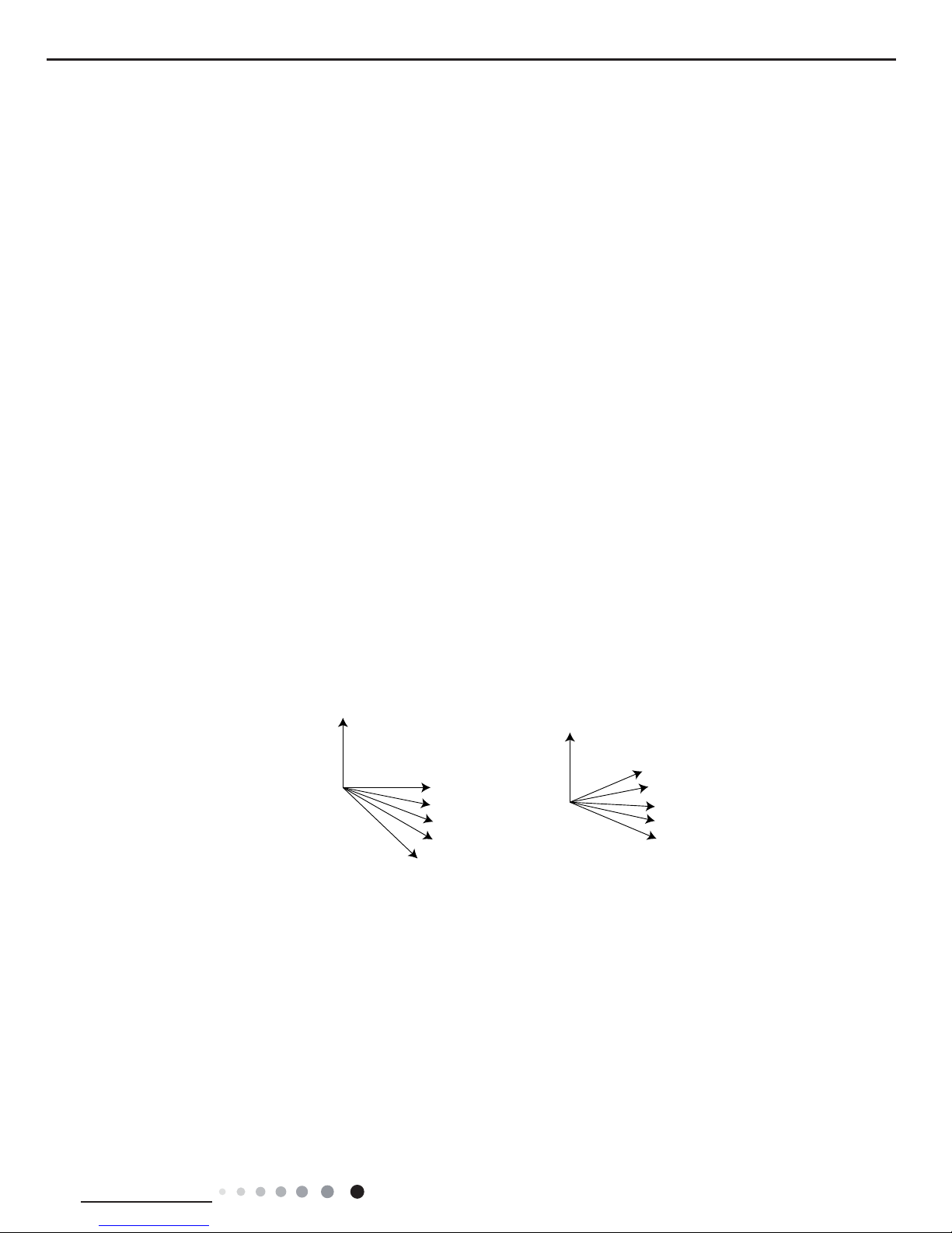
(9) Up-and-Down Swinging Control
When power on, the up-and-down motor will rstly move the air deector to o counter-clockwise, close the air outlet. After starting
the machine, if you don’t set the swinging function, heating mode and auto-heating mode, the up-and-down air deector will move to
D clockwise; under other modes, the up-and-down air deector will move to L1. If you set the swinging function when you start the
machine, then the wind blade will swing between L and D. The air deector has 7 swinging states: Location L, Location A, Location B,
Location C, Location D, Location L to Location D, stop at any location between L-D (the included angle between L~D is the same). The
air deector will be closed at 0 Location, and the swinging is effectual only on condition that setting the swinging order and the inner
fan is running. The indoor fan and compressor may get the power when air deector is on the default location.
(10) Display
①
Operation pattern and mode pattern display
All the display patterns will display for a time when the power on, the operation indication pattern will display in red under standby
status. When the machine is start by remote control, the indication pattern will light and display the current operation mode (the mode
light includes: Cooling, heating and dehumidify). If you close the light key, all the display patterns will close.
②
Double-8 display
According to the different setting of remote control, the nixie light may display the current temperature (the temperature scope is
from 16~30°C) and indoor ambient temperature. The heating and air supply temperature will display 25°C under auto-mode, the
temperature will display 20°C under the auto-heating mode, and the temperature will display H1 under the defrosting mode.(If you set
the fahrenheit temperature display, the nixie light will display according to fahrenheit temperature)
(11) Protection Function and Failure Display
E2: Freeze-proong protection
E4: Exhausting protection
E5: Overcurrent protection
E6: Communication failure
F1: Indoor ambient sensor start and short circuit (continuously measured failure in 5s)
F2: Indoor evaporator sensor start and short circuit (continuously measured failure in 5s)
Heating angle Cooling angle
O(0°)
O(0°)
L
A
B
C
D
L1
A1
B1
C1
D1

20
Technical Information
Service Manual
F3: Outdoor ambient sensor start and short circuit (continuously measured failure in 30s)
F4: Outdoor condenser sensor start and short circuit (continuously measured failure in 30s, and don’t measure within 10 minutes after
defrosted)
F5: Outdoor exhausting sensor start and short circuit (continuously measured failure in 30s after the compressor operated 3 minutes)
H3: Overload protection of compressor
H5: Module protection
PH: High-voltage protection
PL: Low-voltage protection
P1: Nominal cooling and heating test
P2: Maximum cooling and heating test
P3: Medium cooling and heating test
P0: Minimum cooling and heating test.
(12) Drying Function
You may start or stop the drying function under the modes of cooling and dehumidify at the starting status (The modes of automatism,
heating and air supply do not have drying function). When you start the drying function, after stop the machine by pressing the switch
button, you should keep running the inner fans for 2 minutes under low air damper (The swing will operate as the former status within 2
minutes, and other load is stopped), then stop the entire machine; When you stop the drying function, press the switch button will stop
the machine directly.
When you start the drying function, operating the drying button will stop the inner fans and close the guide louver.
(13)Memory Function
When interrupting the power supply memory content: mode, swing function, light, set temperature and wind speed.After interrupted the
power supply, the machine will start when recovering the power according to the memory contentautomatically.
(14)Electric heating band control of outdoor unit
①
Compressor electric heating band control:
a) Start condition: the compressor is in off status and the T
outdoor ambient temperature
≤-5°C.
b) Stop condition: the band is off when either of the below condition is met:
1.The compressor is in on status;
2.The compressor is in off status and the T
outdoor ambient temperature
≥-5°C.
c) When outdoor ambient temperature sensor is in malfunction status, the electric heating band stops operation.
②
Condenser electric heating band control:
1.When T
outdoor ambient
≤1°C, the electric heating band starts working;
2. When enter defrosting and defrosting is nished, the chassis electric heating band starts working for 3min as the compressor
starts. After the compressor starts for 3min and T
outdoor ambient
≥3°C, the electric heating band stops operation.
3.When T
outdoor ambient
≥3°C, the condenser electric heating band doesn’t work.
4.When 1°C<T
outdoor ambient
<3°C, the condenser electric heating band keeps the previous status.
When outdoor ambient temperature sensor is in malfunction status, the electric heating band stops operation; the electric heating
band can work again after 2min of last stop.
(15)Compulsory defrosting function
①
Start up compulsory defrosting function
Under ON status, set heating mode with remote controller and adjust the temperature to 16°C. Press “+, -, +, -, +,-” button successively
within 5s and the complete unit will enter into compulsory defrosting status. Meanwhile, heating indicator will ON 10s and OFF 0.5s
successively. (Note: If complete unit has malfunction or stops operation due to protection, compulsory defrosting function can be started
up after malfunction or protection is resumed.
②
Exit compulsory defrosting mode
After compulsory defrosting is started up, the complete unit will exit defrosting operation according to the actual defrosting result, and the
complete unit will resume normal heating operation.
(16)Refrigerant recovery function (applicable for moving the unit or maintaining the unit)
①
Start up refrigerant recovery function
Set cooling mode with remote controller within 5min after energization, adjust temperature at 16°C and press light button on remote
controller for 3 times successively to any one indoor unit within 3s and then the complete unit will enter into refrigerant recovery status.
All indoor units display Fo. Maintenance person close all liquid valves. After 5min, withstand the thimble of all checking valves with tools
one by one. If there’s no refrigerant spraying out, close corresponding valve immediately, turn off the unit with remote controller and then
remove the connection pipe.
②
Exit refrigerant recovery function
During refrigerant recovery process, if any one indoor unit receives any remote control signal or refrigerant recovery function has
operates for about 25min, refrigerant recovery function will be exited automatically. If the complete unit is at standby status before
refrigerant recovery, the complete unit will still at standby status after refrigerant recovery. If the complete unit is at ON status, the unit will
operate according to original operation mode.
21
Installation and Maintenance
Service Manual
1. Select the installation location according to the requirement of this manual.(See the requirements in installation
part)
2. Handle unit transportation with care; the unit should not
be carried by only one person if it is more than 20kg.
3. When installing the indoor unit and outdoor unit, a sufcient xing bolt must be installed; make sure the installation
support is rm.
4. Ware safety belt if the height of working is above 2m.
5. Use equipped components or appointed components during installation.
6. Make sure no foreign objects are left in the unit after nishing installation.
Electrical Safety Precautions:
7. Notes for Installation and Maintenance
Safety Precautions:
Important!
Please read the safety precautions carefully before
installation and maintenance.
The following contents are very important for installation
and maintenance.
Please follow the instructions below.
●The installation or maintenance must accord with the
instructions.
●Comply with all national electrical codes and local
electrical codes.
●Pay attention to the warnings and cautions in this
manual.
●All installation and maintenance shall be performed by
distributor or qualied person.
●All electric work must be performed by a licensed
technician according to local regulations and the
instructions given in this manual.
●Be caution during installation and maintenance. Prohibit
incorrect operation to prevent electric shock, casualty and
other accidents.
1. Cut off the power supply of air conditioner before
checking and maintenance.
2. The air condition must apply specialized circuit and
prohibit share the same circuit with other appliances.
3. The air conditioner should be installed in suitable
location and ensure the power plug is touchable.
4. Make sure each wiring terminal is connected firmly
during installation and maintenance.
5. Have the unit adequately grounded. The grounding
wire can’t be used for other purposes.
6. Must apply protective accessories such as protective
boards, cable-cross loop and wire clip.
7. The live wire, neutral wire and grounding wire of
power supply must be corresponding to the live wire,
neutral wire and grounding wire of the air conditioner.
8. The power cord and power connection wires can’t be
pressed by hard objects.
9. If power cord or connection wire is broken, it must be
replaced by a qualied person.
1. Avoid contact between refrigerant and re as it generates
poisonous gas; Prohibit prolong the connection pipe by
welding.
2. Apply specied refrigerant only. Never have it mixed with
any other refrigerant. Never have air remain in the refrigerant
line as it may lead to rupture or other hazards.
3. Make sure no refrigerant gas is leaking out when
installation is completed.
4. If there is refrigerant leakage, please take sufficient
measure to minimize the density of refrigerant.
5. Never touch the refrigerant piping or compressor without
wearing glove to avoid scald or frostbite.
Warnings
Refrigerant Safety Precautions:
Improper installation may lead to re hazard, explosion,
electric shock or injury.
Installation Safety Precautions:
Part
Ⅱ
: Installation and Maintenance
10. If the power cord or connection wire is not long enough,
please get the specialized power cord or connection wire
from the manufacture or distributor. Prohibit prolong the wire
by yourself.
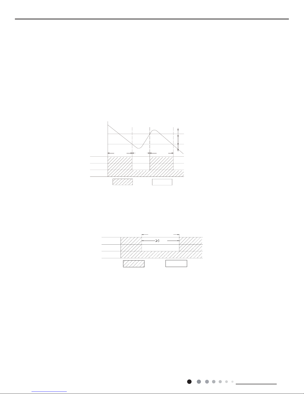
11. For the air conditioner without plug, an air switch must
be installed in the circuit. The air switch should be all-pole
parting and the contact parting distance should be more than
3mm.
12. Make sure all wires and pipes are connected properly and
the valves are opened before energizing.
13. Check if there is electric leakage on the unit body. If yes,
please eliminate the electric leakage.
14. Replace the fuse with a new one of the same specication
if it is burnt down; don’t replace it with a cooper wire or
conducting wire.
15. If the unit is to be installed in a humid place, the circuit
breaker must be installed.
 Loading...