

Gree GWH09RB-K3DNA3C, GWH12RB-K3DNA5C, GWH12RB-K3DNA2C, GWH12RB-K3DNA3C, GWH09RB-K3DNA5C Service Manual
...
GREE ELECTRIC APPLIANCES,INC.OF ZHUHAI
Service Manual
Change for Life
MODELS: GWH09RB-K3DNA2C(CB301001100)
GWH09RB-K3DNA2C(CB301001102)
GWH09RB-K3DNA3C(CB302000900)
GWH09RB-K3DNA3C(CB302000901)
GWH09RB-K3DNA5C(CB304000500)
GWH09RB-K3DNA6C(CB305000100)
GWH09RB-K3DNA8C(CB313000100)
GWH12RB-K3DNA2C(CB301001200)
GWH12RB-K3DNA2C(CB301001202)
GWH12RB-K3DNA3C(CB302001000)
GWH12RB-K3DNA3C(CB302001001)
GWH12RB-K3DNA5C(CB304000600)
GWH12RB-K3DNA6C(CB305000200)
GWH12RB-K3DNA8C(CB313000200)
(Refrigerant R410A)

Table of Contents
Table of Contents
Summary and Features
.........................................................................................1
1. Safety Precautions
..............................................................................................3
2. Specifi cations
..........................................................................................................4
2.1 Unit Specifi cations ............................................................................................................4
2.2 Operation Characteristic Curve ......................................................................................12
2.3 Capacity Variation Ratio According to Temperature .......................................................12
2.4 Operation Data ...............................................................................................................13
2.5 Noise Criteria Curve Tables for Both Models .................................................................13
3. Construction Views
..........................................................................................14
3.1 Indoor Unit ......................................................................................................................14
3.2 Outdoor Unit ...................................................................................................................14
4. Refrigerant System Diagram
....................................................................17
5. Schematic Diagram
..........................................................................................18
5.1 Electrical Wiring ..............................................................................................................18
5.2 Printed Circuit Board ......................................................................................................20
6. Function and Control
......................................................................................22
6.1 Remote Control Operations ............................................................................................22
6.2 Description of Each Control Operation ...........................................................................26
7. Installation Manual
............................................................................................31
7.1 Notices for Installation ....................................................................................................31
7.2 Installation Dimension Diagram ......................................................................................33
7.3 Install Indoor Unit ...........................................................................................................34
7.4 Install Outdoor Unit .........................................................................................................35
7.5 Check after Installation and Test Operation ...................................................................36
7.6 Installation and Maintenance of Healthy Filter ...............................................................37

Table of Contents
8. Exploded Views and Parts List
..............................................................38
8.1 Indoor Unit ......................................................................................................................38
8.2 Outdoor Unit ...................................................................................................................46
9. Troubleshooting
..................................................................................................50
9.1 Malfunction Analysis .......................................................................................................50
9.2 Flashing LED of Indoor/Outdoor Unit and Primary Judgement ......................................54
10. Removal Procedure
.......................................................................................72
10.1 Removal Procedure of Indoor Unit ...............................................................................72
10.2 Removal Procedure of Outdoor Unit ............................................................................77
1
Summary and Features
Summary and Features
Indoor Unit
GWH09RB-K3DNA2C/I(CB301N01100)
GWH09RB-K3DNA2C/I(CB301N01101)
GWH12RB-K3DNA2C/I(CB301N01200)
GWH12RB-K3DNA2C/I(CB301N01201)
GWH09RB-K3DNA3C/I(CB302N00900)
GWH09RB-K3DNA3C/I(CB302N00901)
GWH12RB-K3DNA3C/I(CB302N01000)
GWH12RB-K3DNA3C/I(CB302N01001)
GWH09RB-K3DNA5C/I(CB304N00500)
GWH12RB-K3DNA5C/I(CB304N00600)
GWH09RB-K3DNA8C/I(CB313N00100)
GWH12RB-K3DNA8C/I(CB313N00200)
Outdoor Unit
GWH09RB-K3DNA3C/O(CB302W00900)
GWH09RB-K3DNA6C/I(CB305N00100)
GWH12RB-K3DNA6C/I(CB305N00200)
2
Summary and Features
GWH09RB-K3DNA3C/O(CB302W00901)
GWH12RB-K3DNA3C/O(CB302W01000)
GWH12RB-K3DNA3C/O(CB302W01001)
Remote Controller
YAA1FB
3
Safety Precautions
1. Safety Precautions
Installing, starting up, and servicing air conditioner can be
hazardous due to system pressure, electrical components,
and equipment location, etc.
Only trained, qualified installers and service personnel are
allowed to install, start-up, and service this equipment.
Untrained personnel can perform basic maintenance functions such as cleaning coils. All other operations should
be performed by trained service personnel.
When handling the equipment, observe precautions in the
manual and on tags, stickers, and labels attached to the
equipment. Follow all safety codes. Wear safety glasses
andwork gloves. Keep quenching cloth and fire extinguisher
nearby when brazing.
Read the instructions thoroughly and follow all warnings or
cautions in literature and attached to the unit. Consult local
building codes and current editions of national as well as
local electrical codes.
Recognize the following safety information:
Incorrect handling could result in
personal injury or death.
Incorrect handling may result in
minor injury,or damage to product
or property.
Warning
Caution
Caution
Warning
A
ll electric work must be performed by a licensed technician
according to local regulations and the instructions given in
this manual.
Before installing, modifying, or servicing system, main
electrical disconnect switch must be in the OFF position.
There may be more than 1 disconnect switch. Lock out
and tag switch with a suitable warning label.
Never supply power to the unit unless all wiring and tubing are completed, reconnected and checked.
This system adopts highly dangerous electrical voltage.
Incorrect connection or inadequate grounding can cause
personal injury or death. Stick to the wiring diagram and
all the instructions when wiring.
Have the unit adequately grounded in accordance with
local electrical codes.
All installation or repair work shall be performed by your dealer or a specialized subcontractor as there is the risk of fire,
electric shock, explosion or injury.
Have all wiring connected tightly. Loose connection may
lead to overheating and a possible fire hazard.
Make sure the outdoor unit is installed on a stable, level
surface with no accumulation of snow, leaves, or trash
beside.
Make sure the ceiling/wall is strong enough to bear the
weight of the unit.
Make sure the noise of the outdoor unit does not disturb
neighbors.
Follow all the installation instructions to minimize the risk
of damage from earthquakes, typhoons or strong winds.
Avoid contact between refrigerant and fire as it generates
poisonous gas.
Apply specified refrigerant only. Never have it mixed with
any other refrigerant. Never have air remain in the
refrigerant line as it may lead to rupture and other hazards.
Make sure no refrigerant gas is leaking out when installation is completed.
Should there be refrigerant leakage, the density of refrigerant in the air shall in no way exceed its limited value,
or it may lead to explosion.
Keep your fingers and clothing away from any moving
parts.
Clear the site after installation. Make sure no foreign objects are left in the unit.
Always ensure effective grounding for the unit.
Never install the unit in a place where a combustible gas
might leak, or it may lead to fire or explosion.
Properly insulate any tubing running inside the room to
prevent the water from damaging the wall.
Make a proper provision against noise when the unit is
installed at a telecommunication center or hospital.
Provide an electric leak breaker when it is installed in a
watery place.
Never wash the unit with water.
Should any emergency occur, stop the unit and disconnect the power immediately.
Handle unit transportation with care. The unit should not
be carried by only one person if it is more than 20kg.
Never touch the heat exchanger fins with bare hands.
Never touch the compressor or refrigerant piping without
wearing glove.
Do not have the unit operate without air filter.
4
Specifi cations
2. Specifi cations
2.1 Unit Specifi cations
Model
GWH09RB-K3DNA2C, GWH09RB-K3DNA3C
GWH09RB-K3DNA5C, GWH09RB-K3DNA6C
GWH09RB-K3DNA8C
Product Code
CB301001100, CB302000900
CB304000500, CB305000100
CB313000100
Power
Supply
Rated Voltage V~ 220-240
Rated Frequency Hz 50
Phases 1
Power Supply Mode Indoor
Cooling Capacity (Min~Max) W 2600(880~3000)
Heating Capacity (Min~Max) W 2750(760~3500)
Cooling Power Input (Min~Max) W 720(110~1200)
Heating Power Input (Min~Max) W 720(110~1470)
Cooling Power Current A 3.13
Heating Power Current A 3.13
Rated Input W 1550
Rated Current A 7.00
Air Flow Volume(SH/H/M/L/SL) m
3
/h 650/500/400/300/Dehumidifying Volume L/h 0.80
EER W/W COP W/W SEER W/W 6.40
SCOP W/W 4.00
Application Area m
2
12-18
Indoor Unit
Model of Indoor Unit
GWH09RB-K3DNA2C/I, GWH09RB-K3DNA3C/I
GWH09RB-K3DNA5C/I, GWH09RB-K3DNA6C/I
GWH09RB-K3DNA8C/I
Product Code of Indoor Unit
CB301N01100, CB302N00900
CB304N00500, CB305N00100
CB313N00100
Fan Type Cross-fl ow
Diameter Length(DXL) mm ĭ92X645
Fan Motor Cooling Speed (SH/H/M/L/SL) r/min 1260/1050/900/690/Fan Motor Heating Speed (SH/H/M/L/SL) r/min 1320/1200/1000/910/Output of Fan Motor W 20
Fan Motor RLA A 0.10
Fan Motor Capacitor ȝF 1.0
Input of Heater W Evaporator Form Aluminum Fin-copper Tube
Pipe Diameter mm ĭ7
Row-fi n Gap mm 2-1.4
Coil Length (LXDXW) mm 640X24.8X266.7
Swing Motor Model MP24AA
Output of Swing Motor W 2
Fuse A 3.15
Sound Pressure Level (SH/H/M/L/SL) dB (A) 41/39/36/33/Sound Power Level (SH/H/M/L/SL) dB (A) 53/49/44/38/Dimension (WXHXD) mm 845X275X189
Dimension of Carton Box (LXWXH) mm 923X264X356
Dimension of Package (LXWXH) mm 926X267X371
Net Weight kg 10.0
Gross Weight kg 12.0
5
Specifi cations
The above data is subject to change without notice. Please refer to the nameplate of the unit.
Outdoor
Unit
Model of Outdoor Unit GWH09RB-K3DNA3C/O
Product Code of Outdoor Unit CB302W00900
Compressor Manufacturer/Trademark ZHUHAI LANDA COMPRESSOR CO., LTD.
Compressor Model QXA-A086zE190A
Compressor Oil FVC 68D / RB 68EP
Compressor Type Rotary
L.R.A. A 20.00
Compressor RLA A 4.20
Compressor Power Input W 881
Overload Protector 1NT11L-6233
Throttling Method Electron expansion valve
Operation temp ºC 16~30
Ambient temp (Cooling) ºC 18~43
Ambient temp (Heating) ºC -7~24
Condenser Form Aluminum Fin-copper Tube
Pipe Diameter mm ĭ7
Rows-fi n Gap mm 2-1.4
Coil Length (LXDXW) mm 680X38X506
Fan Motor Speed rpm 900/650
Output of Fan Motor W 30
Fan Motor RLA A 0.15
Fan Motor Capacitor ȝFAir Flow Volume of Outdoor Unit m
3
/h 2000
Fan Type Axial-fl ow
Fan Diameter mm ĭ400
Defrosting Method Automatic Defrosting
Climate Type T1
Isolation I
Moisture Protection IP24
Permissible Excessive Operating Pressure for the
Discharge Side
MPa 4.3
Permissible Excessive Operating Pressure for the
Suction Side
MPa 2.5
Sound Pressure Level (H/M/L) dB (A) 55/-/Sound Power Level (H/M/L) dB (A) 60/-/Dimension (WXHXD) mm 776X540X320
Dimension of Carton Box (LXWXH) mm 848X360X580
Dimension of Package (LXWXH) mm 851X363X595
Net Weight kg 30.0
Gross Weight kg 32.0
Refrigerant R410A
Refrigerant Charge kg 0.90
Connection
Pipe
Length m 5
Gas Additional Charge g/m 20
Outer Diameter Liquid Pipe mm ĭ6
Outer Diameter Gas Pipe mm ĭ9.52
Max Distance Height m 10
Max Distance Length m 15
6
Specifi cations
Model GWH09RB-K3DNA2C, GWH09RB-K3DNA3C
Product Code CB301001102, CB302000901
Power
Supply
Rated Voltage V~ 220-240
Rated Frequency Hz 50
Phases 1
Power Supply Mode Indoor
Cooling Capacity (Min~Max) W 2600(880~3000)
Heating Capacity (Min~Max) W 2750(760~3500)
Cooling Power Input (Min~Max) W 720(110~1200)
Heating Power Input (Min~Max) W 720(110~1470)
Cooling Power Current A 3.13
Heating Power Current A 3.13
Rated Input W 1550
Rated Current A 7.00
Air Flow Volume(SH/H/M/L/SL) m
3
/h 650/500/400/300/-
Dehumidifying Volume L/h 0.80
EER W/W -
COP W/W -
SEER W/W 6.40
SCOP W/W 4.00
Application Area m
2
12-18
Indoor Unit
Model of Indoor Unit GWH09RB-K3DNA2C/I, GWH09RB-K3DNA3C/I
Product Code of Indoor Unit CB301001102, CB302000901
Fan Type Cross-fl ow
Diameter Length(DXL) mm ĭ92X645
Fan Motor Cooling Speed (SH/H/M/L/SL) r/min 1260/1050/900/690/-
Fan Motor Heating Speed (SH/H/M/L/SL) r/min 1320/1200/1000/910/-
Output of Fan Motor W 20
Fan Motor RLA A 0.10
Fan Motor Capacitor ȝF 1.0
Input of Heater W -
Evaporator Form Aluminum Fin-copper Tube
Pipe Diameter mm ĭ7
Row-fi n Gap mm 2-1.4
Coil Length (LXDXW) mm 640X24.8X266.7
Swing Motor Model MP24AA
Output of Swing Motor W 2
Fuse A 3.15
Sound Pressure Level (SH/H/M/L/SL) dB (A) 41/39/36/33/-
Sound Power Level (SH/H/M/L/SL) dB (A) 53/49/44/38/-
Dimension (WXHXD) mm 845X275X189
Dimension of Carton Box (LXWXH) mm 923X264X356
Dimension of Package (LXWXH) mm 926X267X371
Net Weight kg 10.0
Gross Weight kg 12.0
7
Specifi cations
The above data is subject to change without notice. Please refer to the nameplate of the unit.
Outdoor
Unit
Model of Outdoor Unit GWH09RB-K3DNA3C/O
Product Code of Outdoor Unit CB302W00901
Compressor Manufacturer/Trademark ZHUHAI LANDA COMPRESSOR CO., LTD.
Compressor Model QXA-A086zE190A
Compressor Oil FVC 68D / RB 68EP
Compressor Type Rotary
L.R.A. A 20.00
Compressor RLA A 4.20
Compressor Power Input W 881
Overload Protector 1NT11L-6233
Throttling Method Electron expansion valve
Operation temp ºC 16~30
Ambient temp (Cooling) ºC 18~43
Ambient temp (Heating) ºC -7~24
Condenser Form Aluminum Fin-copper Tube
Pipe Diameter mm ĭ7
Rows-fi n Gap mm 2-1.4
Coil Length (LXDXW) mm 680X38X506
Fan Motor Speed rpm 900/650
Output of Fan Motor W 30
Fan Motor RLA A 0.15
Fan Motor Capacitor ȝF-
Air Flow Volume of Outdoor Unit m
3
/h 2000
Fan Type Axial-fl ow
Fan Diameter mm ĭ400
Defrosting Method Automatic Defrosting
Climate Type T1
Isolation I
Moisture Protection IP24
Permissible Excessive Operating Pressure for the
Discharge Side
MPa 4.3
Permissible Excessive Operating Pressure for the
Suction Side
MPa 2.5
Sound Pressure Level (H/M/L) dB (A) 55/-/-
Sound Power Level (H/M/L) dB (A) 60/-/-
Dimension (WXHXD) mm 776X540X320
Dimension of Carton Box (LXWXH) mm 848X360X580
Dimension of Package (LXWXH) mm 851X363X595
Net Weight kg 30.0
Gross Weight kg 32.0
Refrigerant R410A
Refrigerant Charge kg 0.90
Connection
Pipe
Length m 5
Gas Additional Charge g/m 20
Outer Diameter Liquid Pipe mm ĭ6
Outer Diameter Gas Pipe mm ĭ9.52
Max Distance Height m 10
Max Distance Length m 15

8
Specifi cations
Model
GWH12RB-K3DNA2C, GWH12RB-K3DNA3C
GWH12RB-K3DNA5C, GWH12RB-K3DNA6C
GWH12RB-K3DNA8C
Product Code
CB301001200, CB302001000
CB304000600, CB305000200
CB313000200
Power
Supply
Rated Voltage V~ 220-240
Rated Frequency Hz 50
Phases 1
Power Supply Mode Indoor
Cooling Capacity (Min~Max) W 3500(480~4000)
Heating Capacity (Min~Max) W 3650(650~4280)
Cooling Power Input (Min~Max) W 1100(110~1300)
Heating Power Input (Min~Max) W 1100(110~1580)
Cooling Power Current A 4.78
Heating Power Current A 4.78
Rated Input W 1700
Rated Current A 8.00
Air Flow Volume(SH/H/M/L/SL) m
3
/h 650/500/400/300/Dehumidifying Volume L/h 1.20
EER W/W COP W/W SEER W/W 6.40
SCOP W/W 3.80
Application Area m
2
16-24
Indoor Unit
Model of Indoor Unit
GWH12RB-K3DNA2C/I, GWH12RB-K3DNA3C/I
GWH12RB-K3DNA5C/I, GWH12RB-K3DNA6C/I
GWH12RB-K3DNA8C/I
Product Code of Indoor Unit
CB301N01200, CB302N01000
CB304N00600, CB305N00200
CB313N00200
Fan Type Cross-fl ow
Diameter Length(DXL) mm ĭ92X645
Fan Motor Cooling Speed (SH/H/M/L/SL) r/min 1290/1070/900/690/Fan Motor Heating Speed (SH/H/M/L/SL) r/min 1280/1050/980/920/Output of Fan Motor W 20
Fan Motor RLA A 0.10
Fan Motor Capacitor ȝF 1.0
Input of Heater W Evaporator Form Aluminum Fin-copper Tube
Pipe Diameter mm ĭ7
Row-fi n Gap mm 2-1.4
Coil Length (LXDXW) mm 640X24.8X266.7
Swing Motor Model MP24AA
Output of Swing Motor W 2
Fuse A 3.15
Sound Pressure Level (SH/H/M/L/SL) dB (A) 45/42/39/36/Sound Power Level (SH/H/M/L/SL) dB (A) 55/52/49/46/Dimension (WXHXD) mm 845X275X189
Dimension of Carton Box (LXWXH) mm 923X264X356
Dimension of Package (LXWXH) mm 926X267X371
Net Weight kg 10.0
Gross Weight kg 12.0
9
Specifi cations
The above data is subject to change without notice. Please refer to the nameplate of the unit.
Outdoor
Unit
Model of Outdoor Unit GWH12RB-K3DNA3C/O
Product Code of Outdoor Unit CB302W01000
Compressor Manufacturer/Trademark ZHUHAI LANDA COMPRESSOR CO., LTD.
Compressor Model QXA-A091zE190A
Compressor Oil FVC 68D / RB 68EP
Compressor Type Rotary
L.R.A. A 20.00
Compressor RLA A 4.50
Compressor Power Input W 942
Overload Protector 1NT11L-6233
Throttling Method Electron expansion valve
Operation temp ºC 16~30
Ambient temp (Cooling) ºC 18~43
Ambient temp (Heating) ºC -7~24
Condenser Form Aluminum Fin-copper Tube
Pipe Diameter mm ĭ9.52
Rows-fi n Gap mm 2-1.4
Coil Length (LXDXW) mm 730X38.1X508
Fan Motor Speed rpm 900/650
Output of Fan Motor W 30
Fan Motor RLA A 0.15
Fan Motor Capacitor ȝFAir Flow Volume of Outdoor Unit m
3
/h 2000
Fan Type Axial-fl ow
Fan Diameter mm ĭ400
Defrosting Method Automatic Defrosting
Climate Type T1
Isolation I
Moisture Protection IP24
Permissible Excessive Operating Pressure for the
Discharge Side
MPa 4.3
Permissible Excessive Operating Pressure for the
Suction Side
MPa 2.5
Sound Pressure Level (H/M/L) dB (A) 58/-/Sound Power Level (H/M/L) dB (A) 63/-/Dimension (WXHXD) mm 848X540X320
Dimension of Carton Box (LXWXH) mm 878X360X580
Dimension of Package (LXWXH) mm 881X363X595
Net Weight kg 33.0
Gross Weight kg 35.0
Refrigerant R410A
Refrigerant Charge kg 1.15
Connection
Pipe
Length m 5
Gas Additional Charge g/m 20
Outer Diameter Liquid Pipe mm ĭ6
Outer Diameter Gas Pipe mm ĭ9.52
Max Distance Height m 10
Max Distance Length m 20

10
Specifi cations
Model GWH12RB-K3DNA2C, GWH12RB-K3DNA3C
Product Code CB301001202, CB302001001
Power
Supply
Rated Voltage V~ 220-240
Rated Frequency Hz 50
Phases 1
Power Supply Mode Indoor
Cooling Capacity (Min~Max) W 3500(480~4000)
Heating Capacity (Min~Max) W 3650(650~4280)
Cooling Power Input (Min~Max) W 1100(110~1300)
Heating Power Input (Min~Max) W 1100(110~1580)
Cooling Power Current A 4.78
Heating Power Current A 4.78
Rated Input W 1700
Rated Current A 8.00
Air Flow Volume(SH/H/M/L/SL) m
3
/h 650/500/400/300/-
Dehumidifying Volume L/h 1.20
EER W/W -
COP W/W -
SEER W/W 6.40
SCOP W/W 3.80
Application Area m
2
16-24
Indoor Unit
Model of Indoor Unit GWH12RB-K3DNA2C/I, GWH12RB-K3DNA3C/I
Product Code of Indoor Unit CB301N01201, CB302N01001
Fan Type Cross-fl ow
Diameter Length(DXL) mm ĭ92X645
Fan Motor Cooling Speed (SH/H/M/L/SL) r/min 1290/1070/900/690/-
Fan Motor Heating Speed (SH/H/M/L/SL) r/min 1280/1050/980/920/-
Output of Fan Motor W 20
Fan Motor RLA A 0.10
Fan Motor Capacitor ȝF 1.0
Input of Heater W -
Evaporator Form Aluminum Fin-copper Tube
Pipe Diameter mm ĭ7
Row-fi n Gap mm 2-1.4
Coil Length (LXDXW) mm 640X24.8X266.7
Swing Motor Model MP24AA
Output of Swing Motor W 2
Fuse A 3.15
Sound Pressure Level (SH/H/M/L/SL) dB (A) 45/42/39/36/-
Sound Power Level (SH/H/M/L/SL) dB (A) 55/52/49/46/-
Dimension (WXHXD) mm 845X275X189
Dimension of Carton Box (LXWXH) mm 923X264X356
Dimension of Package (LXWXH) mm 926X267X371
Net Weight kg 10.0
Gross Weight kg 12.0
11
Specifi cations
The above data is subject to change without notice. Please refer to the nameplate of the unit.
Outdoor
Unit
Model of Outdoor Unit GWH12RB-K3DNA3C/O
Product Code of Outdoor Unit CB302W01001
Compressor Manufacturer/Trademark ZHUHAI LANDA COMPRESSOR CO., LTD.
Compressor Model QXA-A091zE190A
Compressor Oil FVC 68D / RB 68EP
Compressor Type Rotary
L.R.A. A 20.00
Compressor RLA A 4.50
Compressor Power Input W 942
Overload Protector 1NT11L-6233
Throttling Method Electron expansion valve
Operation temp ºC 16~30
Ambient temp (Cooling) ºC 18~43
Ambient temp (Heating) ºC -7~24
Condenser Form Aluminum Fin-copper Tube
Pipe Diameter mm ĭ9.52
Rows-fi n Gap mm 2-1.4
Coil Length (LXDXW) mm 730X38.1X508
Fan Motor Speed rpm 900/650
Output of Fan Motor W 30
Fan Motor RLA A 0.15
Fan Motor Capacitor ȝF-
Air Flow Volume of Outdoor Unit m
3
/h 2000
Fan Type Axial-fl ow
Fan Diameter mm ĭ400
Defrosting Method Automatic Defrosting
Climate Type T1
Isolation I
Moisture Protection IP24
Permissible Excessive Operating Pressure for the
Discharge Side
MPa 4.3
Permissible Excessive Operating Pressure for the
Suction Side
MPa 2.5
Sound Pressure Level (H/M/L) dB (A) 58/-/-
Sound Power Level (H/M/L) dB (A) 63/-/-
Dimension (WXHXD) mm 848X540X320
Dimension of Carton Box (LXWXH) mm 878X360X580
Dimension of Package (LXWXH) mm 881X363X595
Net Weight kg 33.0
Gross Weight kg 35.0
Refrigerant R410A
Refrigerant Charge kg 1.15
Connection
Pipe
Length m 5
Gas Additional Charge g/m 20
Outer Diameter Liquid Pipe mm ĭ6
Outer Diameter Gas Pipe mm ĭ9.52
Max Distance Height m 10
Max Distance Length m 20
12
Specifi cations
0
1
2
3
4
5
6
7
8
9
10
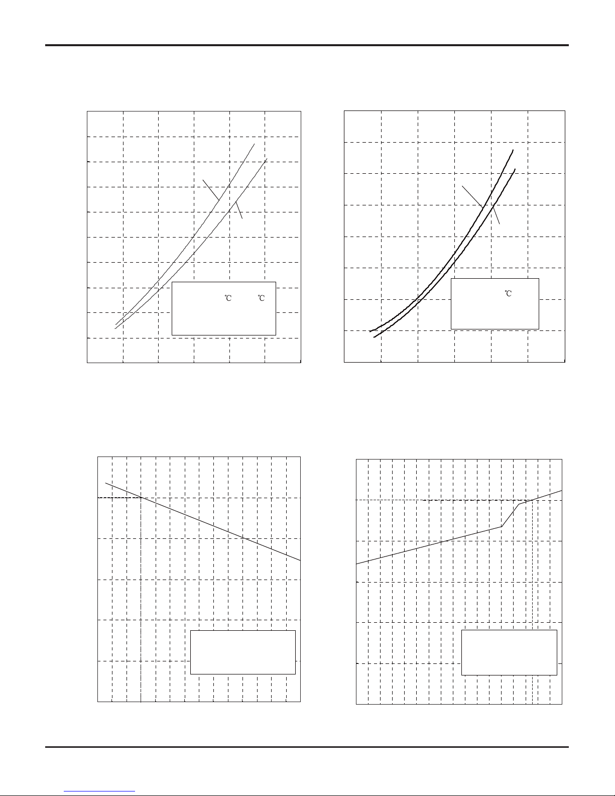
0 20 40 60 80 100 120
Condition
Indoor:DB 27
WB19
Indoor air flow: Turbo
Pipe length:5m
Voltage:230V
Compressor Speed(rps)
0
1
2
3
4
5
6
7
8
0 20 40 60 80 100 120
Condition
Indoor:DB 20
Indoor air flow:Turbo
Pipe length:5m
Voltage:230V
Compressor Speed(rps)
Cooling
Heating
Current(A)
Current(A)
50
60
70
80
90
100
110
32 33 34 35 36 37 38 39 40 41 42 43 44 45 46
Capacity ratio(%)
Condition
Indoor:DB27℃ WB19℃
Indoor air flow:
Turbo
Pipe length:5m
Outdoor temp. (°C)
0
20
40
60
80
100
120
Capacity ratio(%)
Outdoor temp. (°C)
gnitaeHgnilooC
09K
12K
09K
12K
-7 -5 0 5 10
Condition
Indoor:DB20℃
Indoor air flow:
Turbo
Pipe length:5m
2.2 Operation Characteristic Curve
2.3 Capacity Variation Ratio According to Temperature
13
Specifi cations
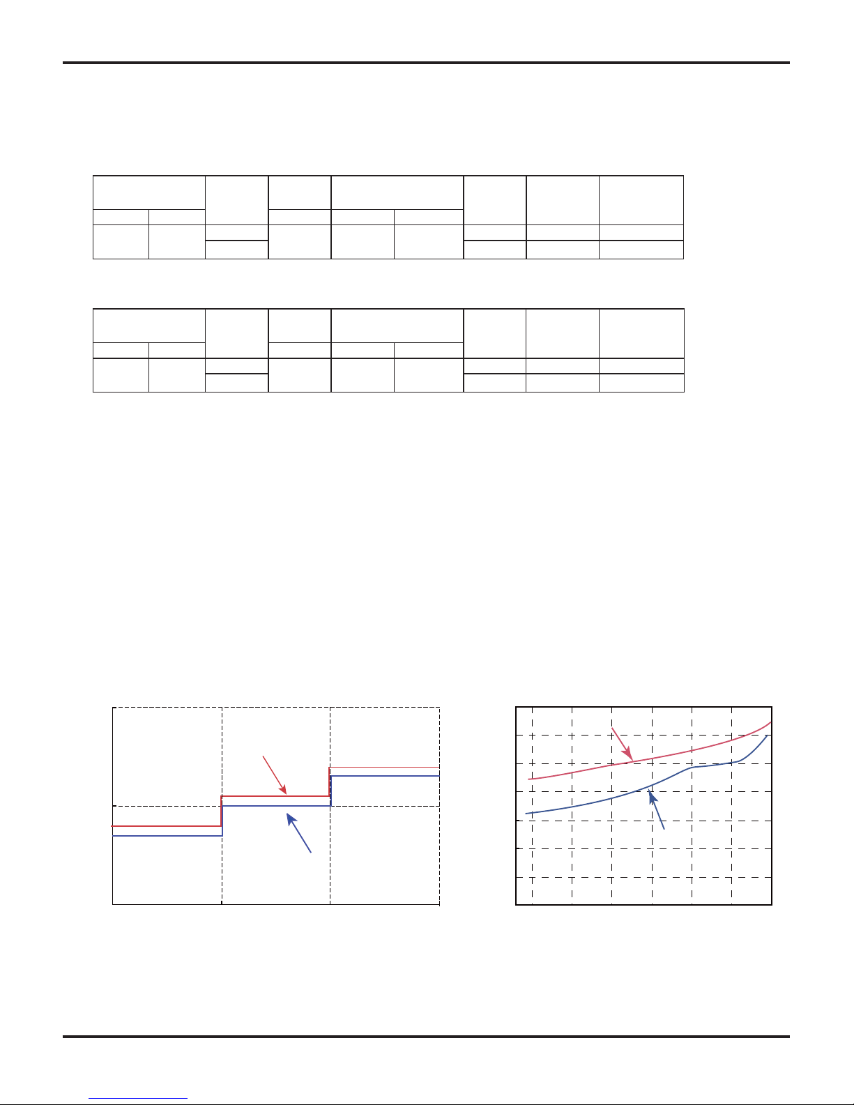
2.5 Noise Criteria Curve Tables for Both Models
2.4 Operation Data
Cooling
NOTES :
(1) Measure surface temperature of heat exchanger pipe around center of heat exchanger path U
bent. (Thermistor themometer)
(2) Connecting piping condition : 5 m
T1: Inlet and outlet pipe temperature of evaporator
T2: Inlet and outlet pipe temperature of condenser
P: Pressure of air pipe connecting indoor and outdoor units
Heating
Temperature
condition (°C)
Model
name
Standard
pressure
Heat exchanger pipe
temp.
Indoor fan
mode
Outdoor fan
mode(rpm)
Compressor
revolution (Hz)
Indoor Outdoor P (MPa) T1 (°C) T2 (°C)
27/19 35/24
09K
0.85~1.0
in:8~11
out:11~14
in:50~80
out:37~43
Turbo 900 54
12K Turbo 900 75
Temperature
condition (°C)
Model
name
Standard
pressure
Heat exchanger pipe
temp.
Indoor fan
mode
Outdoor fan
mode(rpm)
Compressor
revolution (Hz)
Indoor Outdoor P (MPa) T1 (°C) T2 (°C)
20/- 7/6
09K
2.5~3.0
in:50~80
out:37~43
in:1~3
out:2~5
Turbo 900 60
12K Turbo 900 80
45
35
25
Indoor side noise when blowing
Indoor fan motor rotating speed
Low Middle High
12K
40
42
44
46
48
50
52
54
20 4030 50 60 70 80
Compressor frequency(Hz)
Noise dB(A)
Noise dB(A)
Heating
Cooling
09K
14
Construction Views
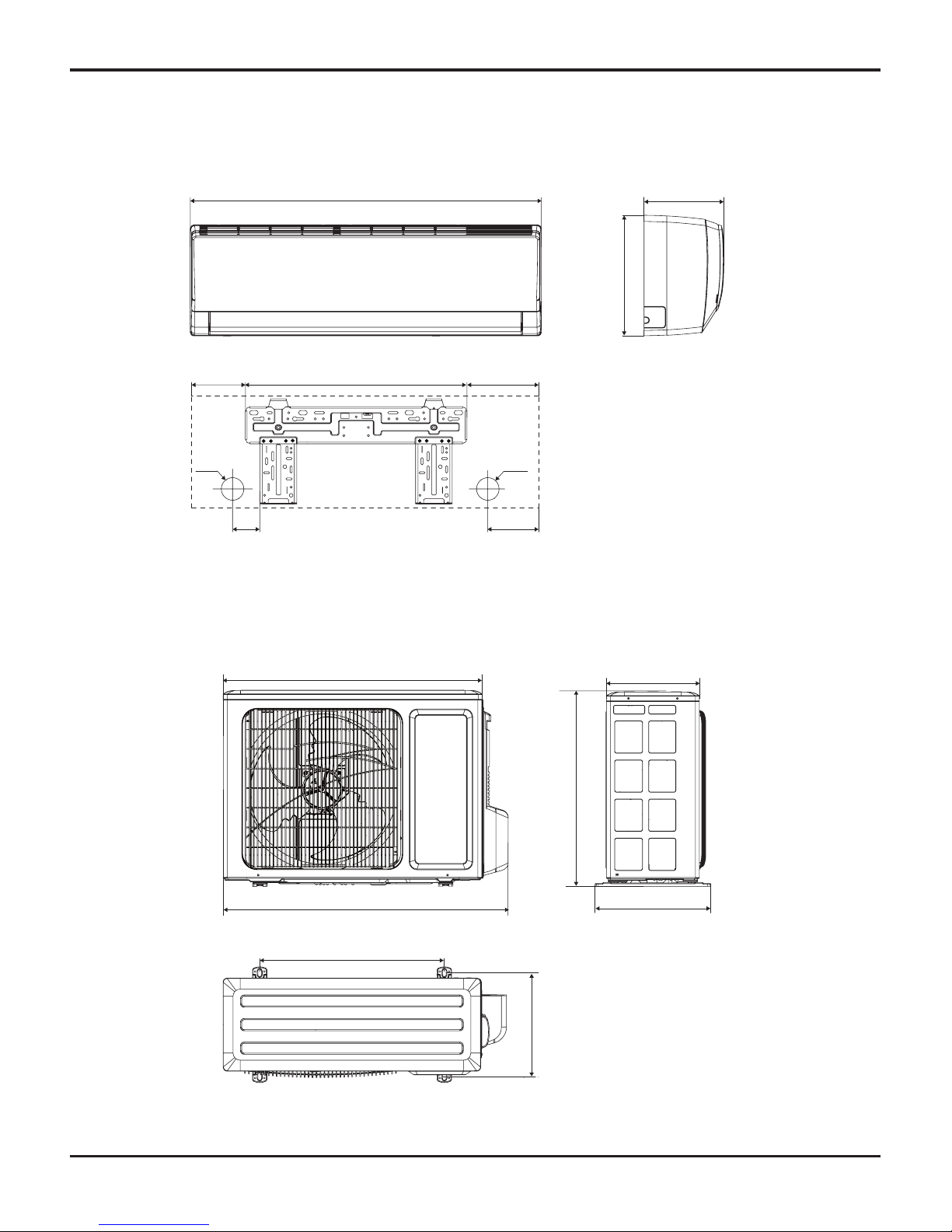
69 124
Φ55
Φ55
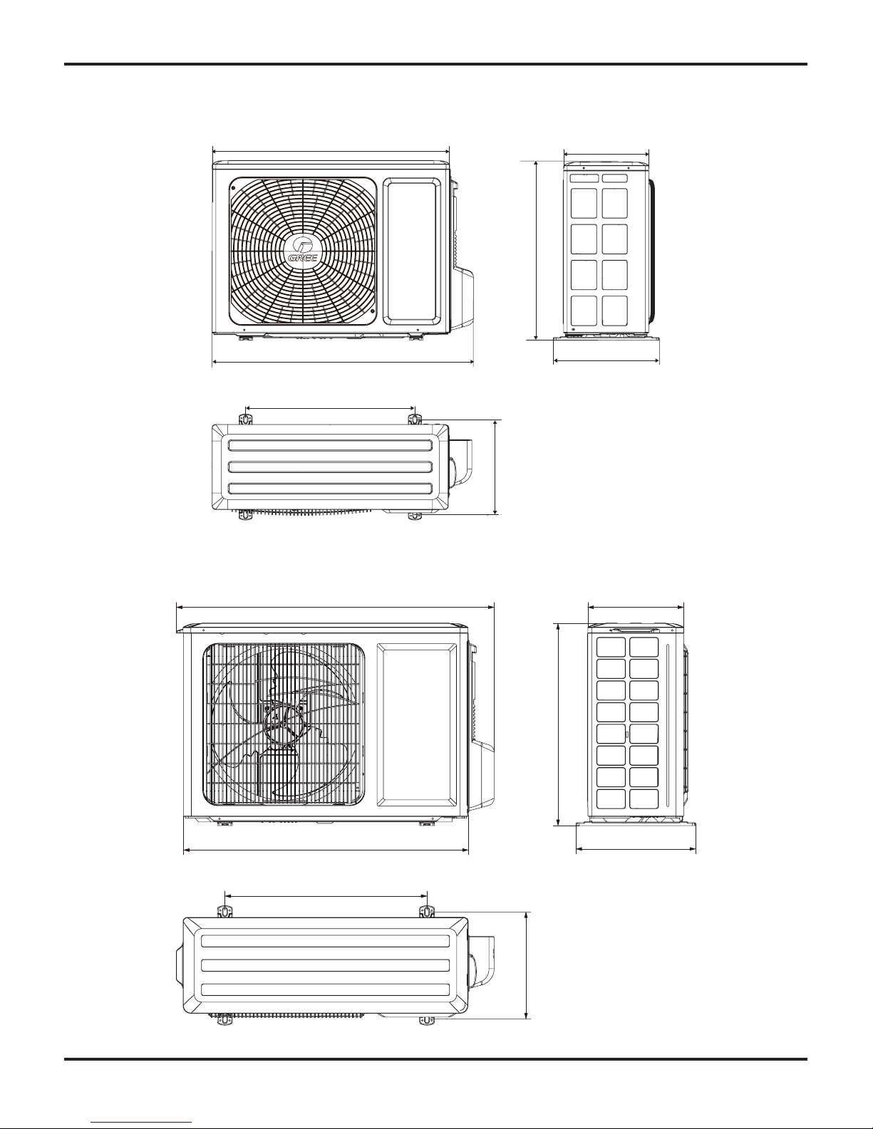
3. Construction Views
3.1 Indoor Unit
845
130
542
173
189
275
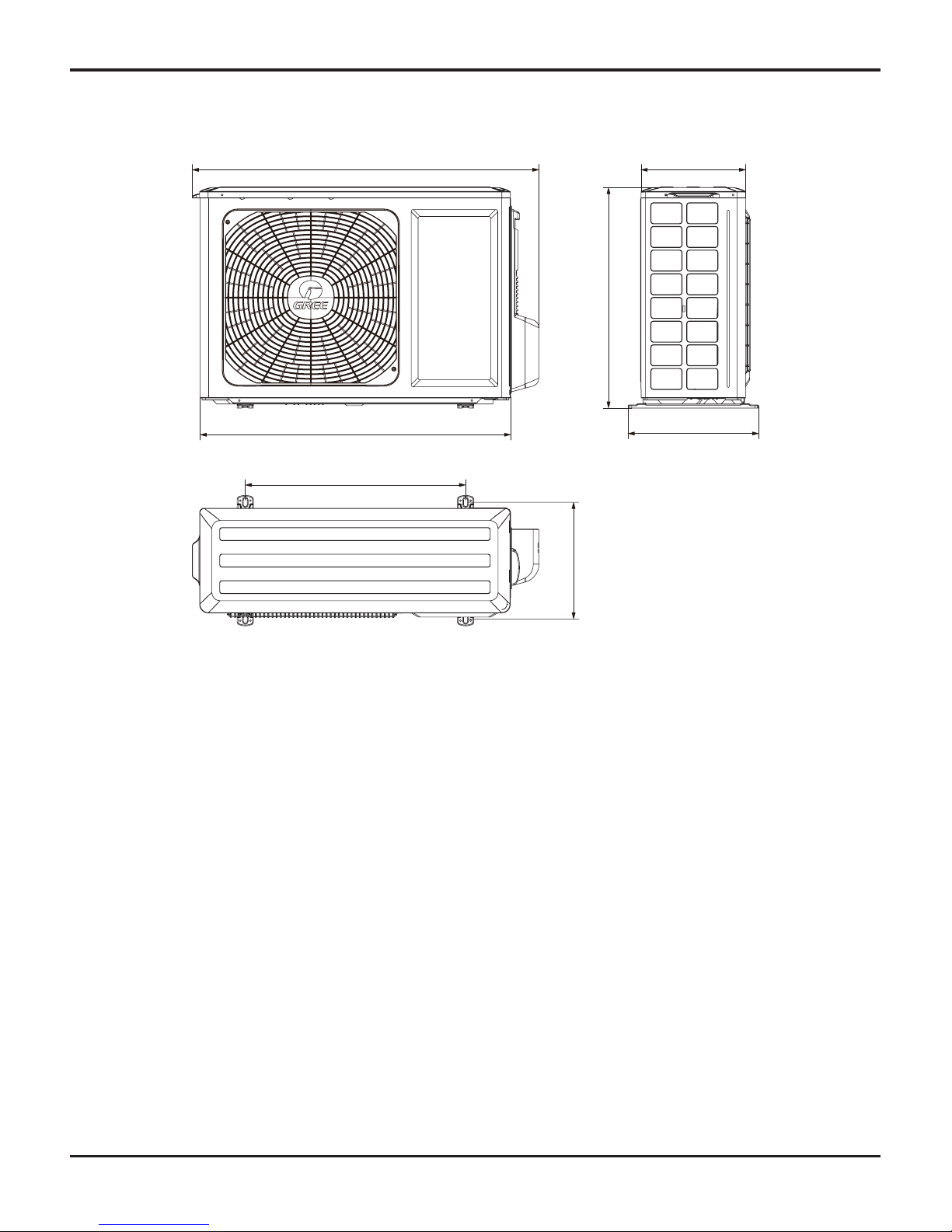
3.2 Outdoor Unit
Unit: mm
257
320
776
540
712
510
286
GWH09RB-K3DNA3C/O(CB302W00900)
15
Construction Views
848
763
540
257
045
320
682
GWH12RB-K3DNA3C/O(CB302W01000)
GWH09RB-K3DNA3C/O(CB302W00901)
257
320
776
540
712
510
286
16
Construction Views
GWH12RB-K3DNA3C/O(CB302W01001)
848
763
540
257
045
320
682
17
Refrigerant System Diagram
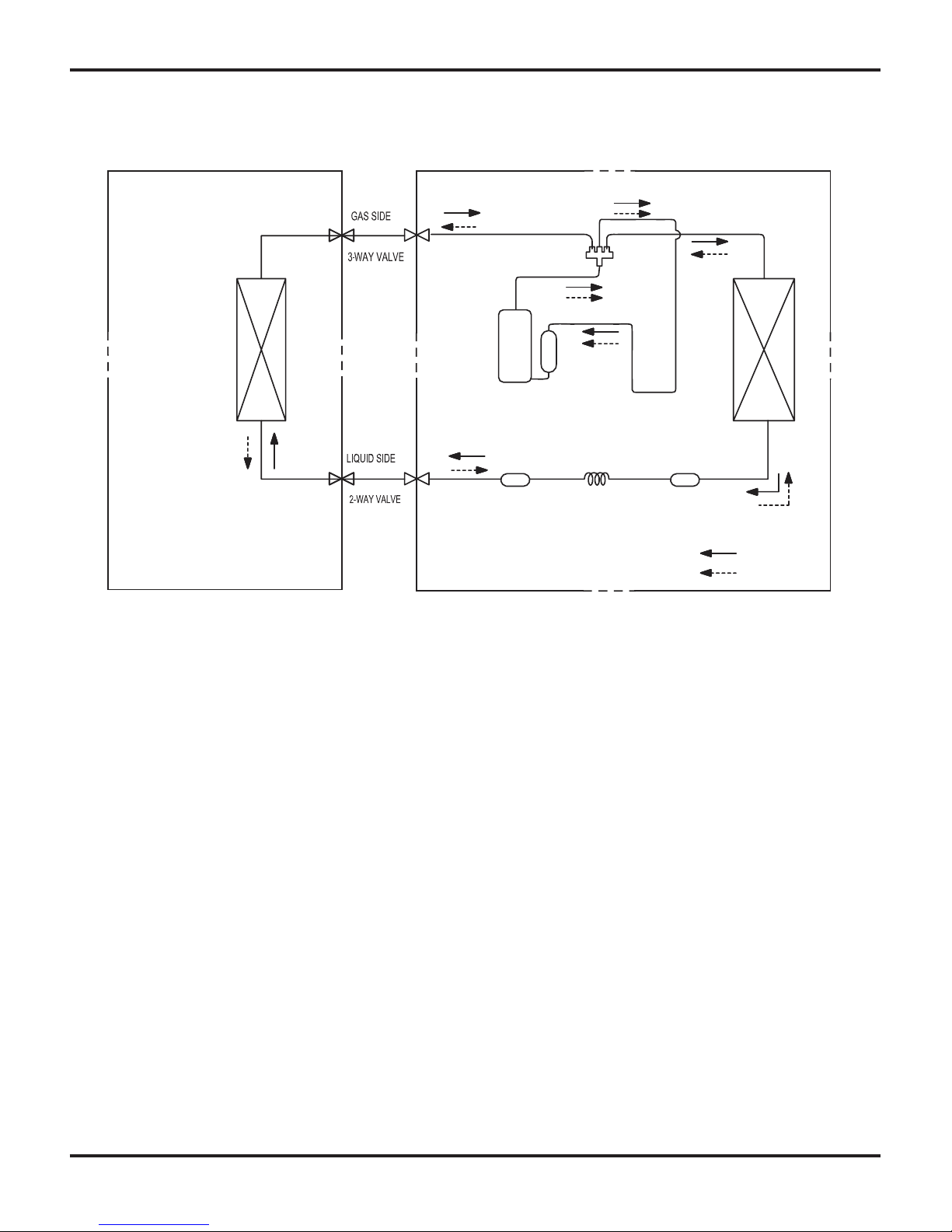
4. Refrigerant System Diagram
Refrigerant pipe diameter
Liquid :1/4" (6 mm)
Gas : 3/8" (9.52 mm)
TINU ROODTUOTINU ROODNI
HEAT
EXCHANGER
(EVAPORATOR)
COOLING
HEATING
HEAT
EXCHANGER
(EVAPORATOR)
Strainer
Strainer
Capillary
Accumlator
Compressor
4-Way valve
18
Schematic Diagram
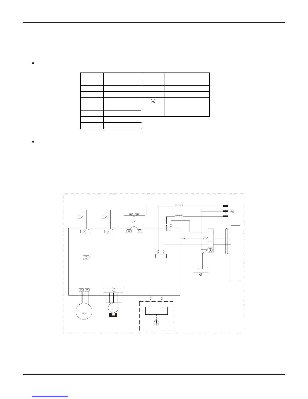
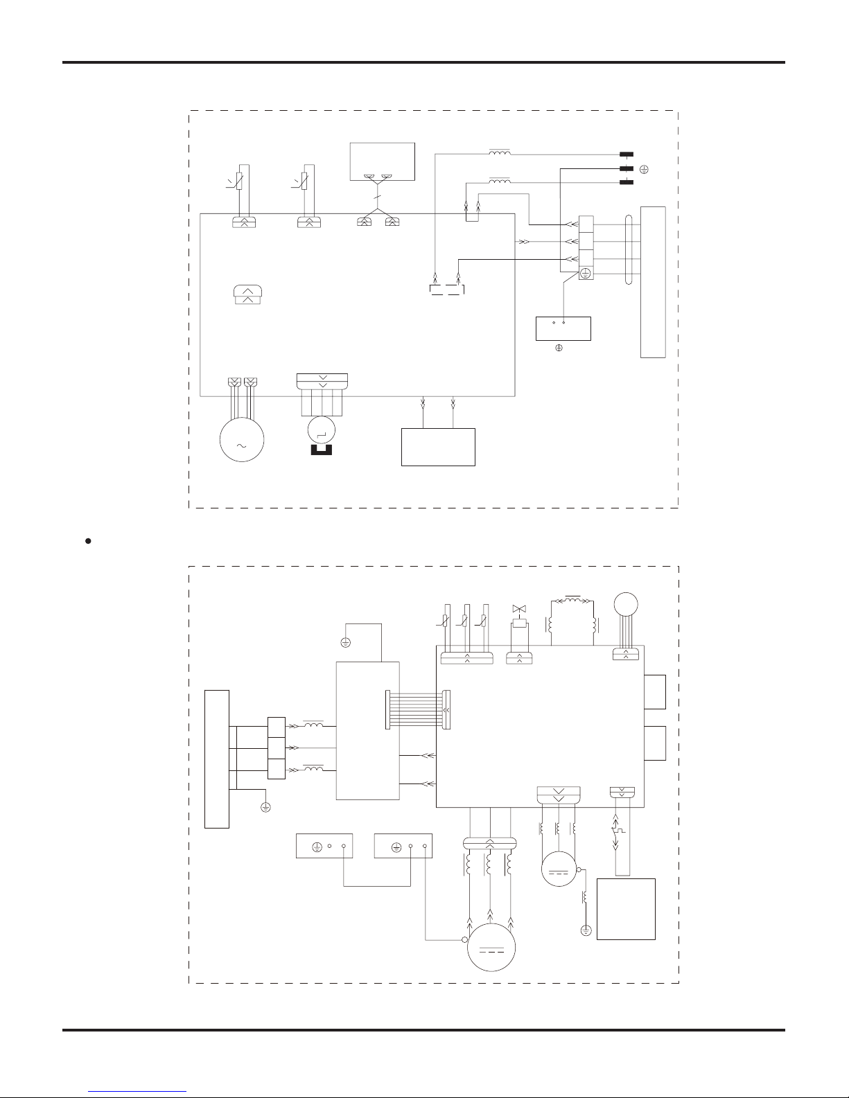
5. Schematic Diagram
5.1 Electrical Wiring
Symbol Color symbol Symbol Parts name
BU BLUE COMP COMPRESSOR
YE YELLOW CT12 OVERLOAD
RD RED 4V 4-WAY VALVE
OG ORANGE PROTECTIVE EARTH
BN BROWN
BK BLACK
YEGN YELLOW GREEN
WH WHITE
ELECTRONIC
EXPANSION VALVE
EKV
Electrical Data
Indoor Unit
L-OUT
L1
L1
00
RT1 RT2
M
JUMP
CAP
TEM.SENSOR
ROOM
TUBE
TEM.SENSOR
FAN MOTOR
SWING MOTOR(U.D)
AP2
SWING-UD
K4
TUBEROOM
AC-L
PG
PGF
DISP-1 DISP-2
CN2
CN1
AP1
DISPLAY
GENERATOR
COOL PLASMA
M
PE
XT1
W1 BU
W3 BN
N(1)
OUTDOOR UNIT
2
3
COM-OUT
W4 YEGN
N
W2 BK
BU
YEGN
BN
L
N
POWER
RD BU
YEGN
HEALTH-NHEALTH-L
PE
BU
BK
BN
YEGN
EVAPORATOR
GWH09RB-K3DNA2C/I(CB301N01100), GWH09RB-K3DNA2C/I(CB301N01101), GWH09RB-K3DNA3C/I(CB302N00900)
GWH09RB-K3DNA5C/I(CB304N00500), GWH09RB-K3DNA8C/I(CB313N00100), GWH12RB-K3DNA2C/I(CB301N01200)
GWH12RB-K3DNA2C/I(CB301N01201), GWH12RB-K3DNA3C/I(CB302N01000), GWH12RB-K3DNA5C/I(CB304N00600)
GWH12RB-K3DNA8C/I(CB313N00200), GWH09RB-K3DNA6C/I(CB305N00100), GWH12RB-K3DNA6C/I(CB305N00200)
19
Schematic Diagram
Outdoor Unit
These circuit diagrams are subject to change without notice, please refer to the one supplied with the unit.
N(1)
XT
3
2
BN
N
AC-L
PE
U
V
W
TUBE
TEM.SENSOR
θ
RT1
RT2
RT3
CN2 4V
N1
AC-L1
L
FAN
OFAN
COMP
COMP
AC-N1
PE
M
PE PE
SHEET
ELECTRIC BOX
4YV
AC-N2
AP1
AP2
AC-L
AC-N
W3
W5
W9
W10
W11
W12
W13
W14 W15
W16
W17 W18
W19
W20
L1
L2
E
W21
AC-L3
AC-L2
LX1-2
LX1-1
OVC-COMP
COM-OUT
L1
PE
PE
CN1
CN3
W7
BK
W2
W1
BU
BN
BK
BU
YEGN
YEGN
YEGN
YEGN
YEGN
BN
BN
BN
BU
BU
BU
BU
BU
RD
RD
YE
YE
TEM.SENSOR
OUTROOM
EXHAUST
TEM.SENSOR
T
I
N
U
R
O
O
D
N
I
W6
L3 L3
L2 L2
W22
SAT
RD
W
V
U
NOTE:
Motor ground
only applies
to the iron
shell motor.
EKV
CN1
L4 L4 L4
L4
MID.ISOLATION
θθ
GWH09RB-K3DNA3C/I(CB302N00901), GWH12RB-K3DNA3C/I(CB302N01001)
0
0
RT1
RT2
M
TUBEROOM
M
PG
PGF
L-OUT
L1
PE
XT1
W1 BU
W3 BN
N(1)
OUTDOOR UNIT
2
3
COM-OUT
W4 YEGN
N
W2 BK
EVAPORATOR
BU
YEGN
BN
L
N
POWER
DISP-1 DISP-2
RD
BU
HEALTH-NHEALTH-L
BU
BK
BN
YEGN
L1
AC-L
K4
SWING-UD
JUMP
CAP
AP2
DISPLAY
AP1
CN1
CN2
TUBE
TEM.SENSORTEM.SENSOR
ROOM
FAN
MOTOR
SWING
MOTOR(U.D)
COOL PLASMA
GENERATOR
20
Schematic Diagram
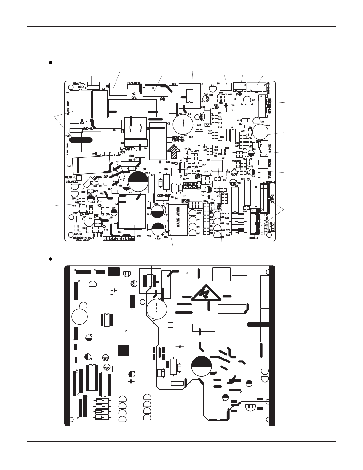
5.2 Printed Circuit Board
(1) Indoor unit
TOP VIEW
BOTTOM VIEW
Live wire of health function
Port of neutral wire
Port of indoor fan
Solid-state relay
Auto button
Feedback of indoor fan
Port of motor for vertical swing
Port of motor for
horizontal swing
Buzzer
Port of indoor ambient
temp sensor
Port of indoor pipe
temp sensor
Port of display
Main chip
Communication port
High-frequency transformer
Power of
switch
Protective
tube

21
Schematic Diagram
inductance pin1
inductance pin2
fan neilsbed
four-way valve
compressor
electric heater
chassis
electric heater
compressor
temp. sensor
overload protection
electric expansion valve
10-core
communication cable
Ɣ
TOP VIEW
Ɣ
BOTTOM VIEW
(2) Outndoor unit
22
Function and Control
6. Function and Control
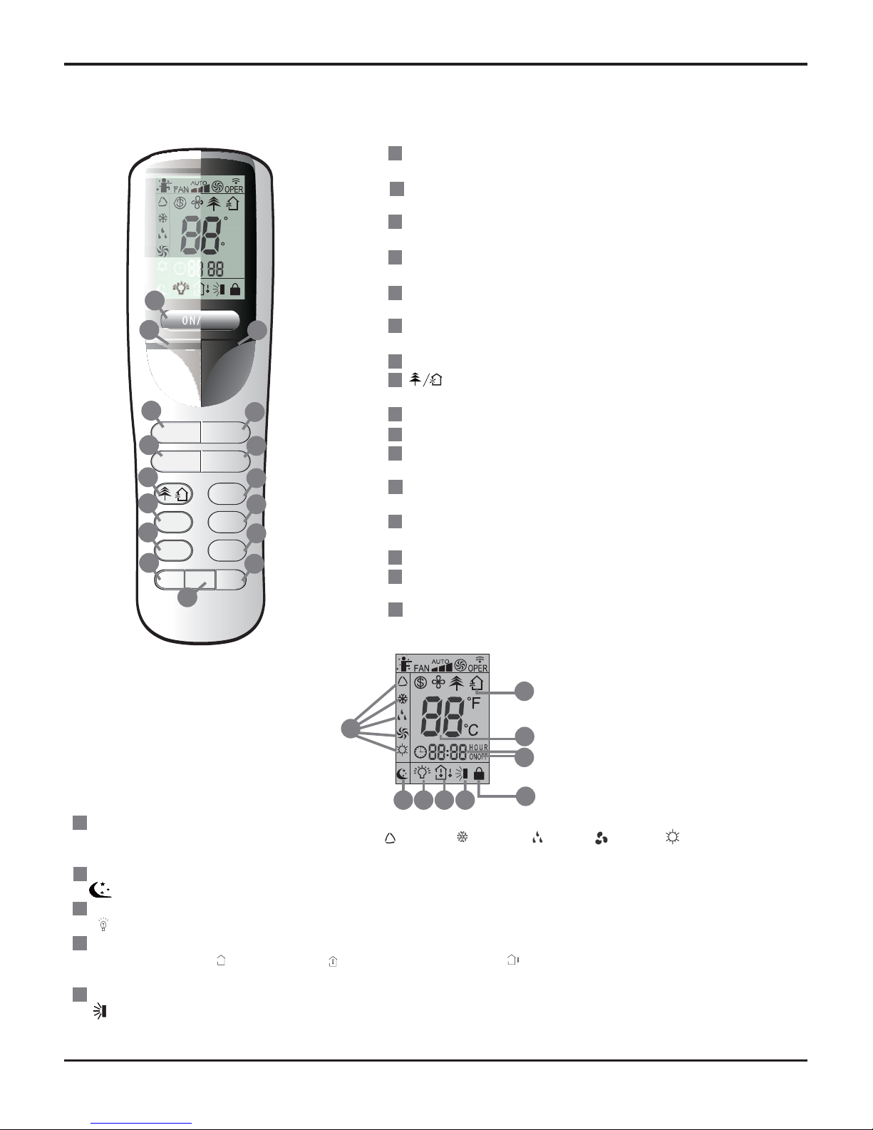
6.1 Remote Control Operations
1
7
8
4
3
5
6
11
13
12
16
10
14
9
15
ON/OFF
Press it to start or stop operation.
-
Press it to decrease temperaturesetting.
+
Press it to increase temperaturesetting.
MODE
Press it to select operation mode(AUTO/COOL/DRY/FAN/HEAT).
FAN
Press it to set fan speed.
SWING
Press it to set swing angle.
I FEEL
Press it to set HEALTH or AIR function.
SLEEP
TEMP
TIMER ON
Press it to set auto-on timer.
CLOCK
Press it to set clock function.
TIMER OFF
Press it to set auto-off timer.
TURBO
LIGHT
Press it to turn on/off the light.
X-FAN
2
17
22
23
25
24
18 19 20 21
19
18
21
20
17
MODE icon:
If MODE button is pressed,current operation mode icon (AUT O), ( COOL), (DR Y), (F AN) or (HEA T only for heat
pumpmodels) will show .
SLEEP icon :
is displayed by pressing the SLEEP button. Press this button again to clear the display .
LIGHT icon:
is displayed by pressing the LIGHT button. Press LIGHT button again to clear the display .
TEMP icon:
Pressing TEMP button, (set temperature), (indoor ambient temperature) , (outdoor ambient temperature) and blank is displayed
circularly .
Up & down swing icon:
is displayed when pressing the up & down swing down button. Press this button again to clear the displa y.
21 2))
02'( )$1
6:,1* ,)( (/
6/((3
7(03
7,0(521
&/2&.
7 2)),0(5
785%2 /,*+7;)$1
)
&
£”
+285
212))
3
15
5
4
14
7
16
13
12
9
8
11
10
2
1
6
23
Function and Control
24
23
26
27
28
29
30
31
1
2
3
4
5
25
22
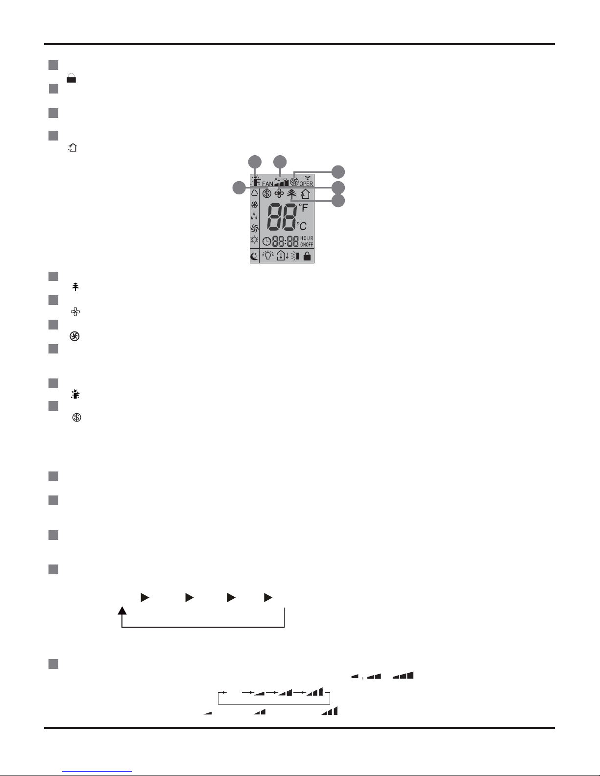
LOCK icon:
is displayed by pressing "+" and “-” buttons simultaneously. Press them again to clear the display.
SET TIME display:
After pressing TIMER button,ON or OFF will blink.This area will show the set time.
DIGITAL display:
This area will show the set temperature. In SAVE mode,"SE" will be displayed.
AIR icon:
is displayed when pressing the AIR button.Press this button again to clear the display.
HEALTH icon:
is displayed when pressing the HEALTH button.Press this button again to clear the display.
X-FAN icon:
is displayed when pressing the X-FAN button. Press this button again to clear the display.
TURBO icon:
is displayed when pressing the TURBO button.Press this button again to clear the display.
FAN SPEED display:
Press FAN button to select the desired fan speed setting(AUTOLow-Med-High).Your selection will be displayed in the LCD windows,
except the AUTO fan speed.
I FEEL icon:
is displayed when pressing the I FEEL button.Press this button again to clear the display.
8℃ Heating icon:
is displayed when Pressing “TEMP” and “CLOCK” simultaneously in Heat mode.
Remote Controller Description
ON/OFF :
Press this button to turn on the unit. Press this button again to turn off the unit.
-:
Press this button to decrease set temperature. Hold it down for above 2 seconds to rapidly decrease set temperature. In AUTO mode,
set temperature is not adjustable.
+:
Press this button to increase set temperature. Hold it down for above 2 seconds to rapidly increase set temperature. In AUTO mode,
set temperature is not adjustable.
MODE :
Each time you press this button, a mode is selected in a sequence that goes from AUTO, COOL,DRY, FAN,and HEAT *, as the following:
After energization, AUTO mode is defaulted. In AUTO mode, the set temperature will not be displayed on the LCD, and the unit will
automatically select the suitable operation mode in accordance with the room temperature to make indoor room comfortable.
FAN :
This button is used for setting Fan Speed in the sequence that goes from AUTO, to then back to Auto.
2930
26
2731
28
AUTO COOL DRY FAN HEAT*
*Note:Only for models with heating function.
Auto
Low speed
Medium speed
High speed
 Loading...