

Gree GWH12MB-K3DNE3G, GWH09MB-K3DNE3G Service Manual

GREE ELECTRIC APPLIANCES,INC.OF ZHUHAI
Change for Life
Service Manual
GWH09MB-K3DNE3G
GWH12MB-K3DNE3G
Model:
(Refrigerant:R410A)

Service Manual
Table of contents
Table of Contents
Part
Ⅰ
: Technical Information
............................................................................1
1. Summary
...........................................................................................................................1
2. Specications
............................................................................................................... 2
2.1 Specication Sheet ................................................................................................................ 2
2.2 Operation Characteristic Curve ............................................................................................. 4
2.3 Capacity Variation Ratio According to Temperature .............................................................. 4
2.4 Cooling and Heating Data Sheet in Rated Frequency ..........................................................5
2.5 Noise Curve ............................................................................................................................5
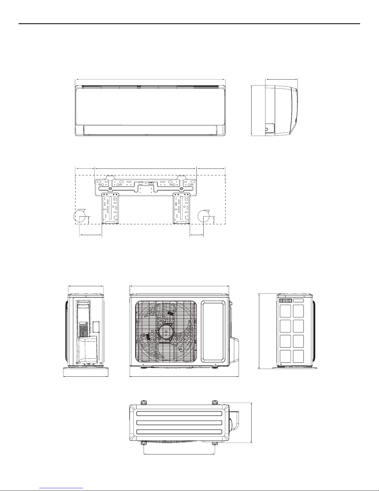
3. Outline Dimension Diagram
..............................................................................................6
3.1 Indoor Unit .............................................................................................................................6
3.2 Outdoor Unit ..........................................................................................................................6
4. Refrigerant System Diagram
...........................................................................7
5. Electrical Part
................................................................................................................8
5.1 Wiring Diagram ......................................................................................................................8
5.2 PCB Printed Diagram ..........................................................................................................10
6. Function and Control
...........................................................................................12
6.1 Remote Controller Introduction ..........................................................................................12
6.2 Brief Description of Modes and Functions ...........................................................................16
Part
Ⅱ
: Installation and Maintenance
......................................................22
7. Notes for Installation and Maintenance
...............................................22
8. Installation
.....................................................................................................................24
8.1 Installation Dimension Diagram ...........................................................................................24
8.2 Installation Parts-checking .................................................................................................26
8.3 Selection of Installation Location .........................................................................................26
8.4 Electric Connection Requirement ........................................................................................26
8.5 Installation of Indoor Unit .....................................................................................................26
8.6 Installation of Outdoor Unit ..................................................................................................29
8.7 Vacuum Pumping and Leak Detection ................................................................................30
8.8 Check after Installation and Test Operation ........................................................................30

Service Manual
9. Maintenance
.................................................................................................................31
9.1 Error Code List ....................................................................................................................31
9.2 Troubleshooting for Main Malfunction .................................................................................38
9.3 Troubleshooting for Normal Malfunction ..............................................................................53
10. Exploded View and Parts’ List
..................................................................55
10.1 Indoor Unit .........................................................................................................................55
10.2 Outdoor Unit ......................................................................................................................58
11. Removal Procedure
............................................................................................64
11.1 Removal Procedure of Indoor Unit ....................................................................................64
11.2 Removal Procedure of Outdoor Unit .................................................................................67
Appendix:
.............................................................................................................................72
Appendix 1: Reference Sheet of Celsius and Fahrenheit .........................................................72
Appendix 2: Conguration of Connection Pipe ..........................................................................72
Appendix 3: Pipe Expanding Method ........................................................................................73
Appendix 4: List of Resistance for Temperature Sensor ...........................................................74
1
Technical Information
Service Manual
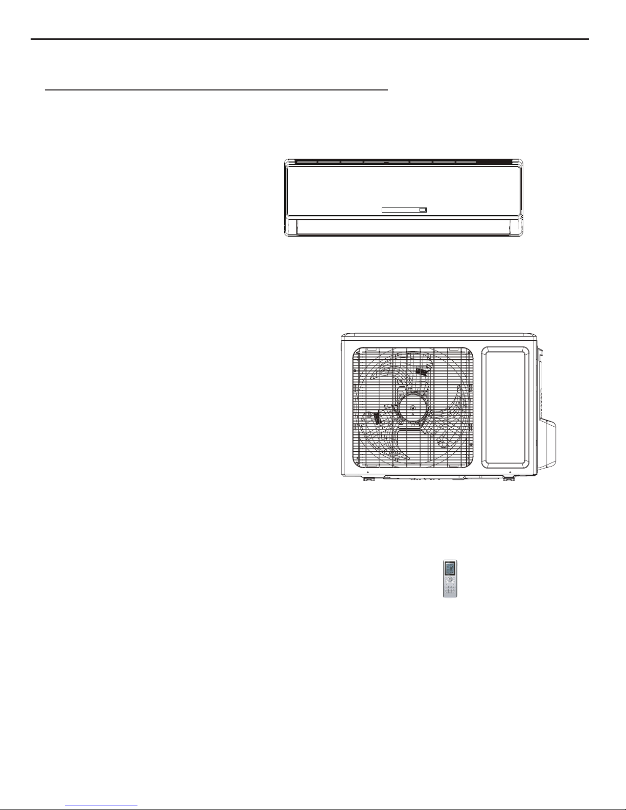
1. Summary
Indoor Unit:
Part
Ⅰ
: Technical Information
Remote Controller:
YT1F(MOTO)
Outdoor Unit:
GWH09MB-K3DNE3G/I
GWH12MB-K3DNE3G/I
GWH09MB-K3DNE3G/O
GWH12MB-K3DNE3G/O
2. Specifications
2.1 Specification Sheet
Model
GWH09MB-K3DNE3G
GWH12MB-K3DNE3G
Product Code
CB404003600
CB404003601
CB404003500
CB404003501
Rated Voltage V~ 220-240 220-240
Rated Frequency Hz 50 50
Power
Supply
Phases 1 1
Power Supply Mode Indoor Indoor
Cooling Capacity (Min~Max) W 2600(600~3200) 3500(600~3900)
Heating Capacity (Min~Max) W 3000(800~3600) 4000(880~4400)
Cooling Power Input (Min~Max) W 870(185~1300) 1170(185~1400)
Heating Power Input (Min~Max) W 900(220~1400) 1200(250~1550)
Cooling Power Current A 3.8 5.2
Heating Power Current A 3.92 5.3
Rated Input W 1400 1600
Rated Current A 6.69 7.8
Air Flow Volume(SH/H/M/L/SL) m3/h 600/500/400/300/- 600/500/400/300/Dehumidifying Volume L/h 0.8 1.2
EER W/W 2.99 2.99
COP W/W 3.33 3.33
SEER W/W 6.1 6.1
HSPF W/W 4.0 4.0
Application Area m2 12-18 16-24
Model of Indoor Unit
GWH09MB-K3DNE3G/I GWH12MB-K3DNE3G/I
Indoor Unit Product Code
CB404N03600/CB404N03601 CB404N03500/CB404N03501
Fan Type Cross-flow Cross-flow
Diameter Length(DXL) mm Φ92X645 Φ92X645
Fan Motor Cooling Speed
(SH/H/M/L/SL)
r/min 1260/1050/900/690/- 1290/1070/900/690/-
Fan Motor Heating Speed
(SH/H/M/L/SL)
r/min 1320/1200/1000/910/- 1280/1050/980/920/-
Output of Fan Motor W 20 20
Fan Motor RLA A 0.1 0.1
Fan Motor Capacitor μF 1.0 1.0
Input of Heater W - Evaporator Form Aluminum Fin-copper Tube Aluminum Fin-copper Tube
Pipe Diameter mm Φ7 Φ7
Row-fin Gap mm 2-1.4 2-1.4
Coil Length (LXDXW) mm 636X25.4X267 636X25.4X267
Swing Motor Model MP24AA MP24AA
Output of Swing Motor W 2 2
Fuse A 3.15 3.15
Sound Pressure Level (SH/H/M/L/SL) dB
(A)
42/39/34/28/- 42/40/35/30/-
Sound Power Level (SH/H/M/L/SL) dB
(A)
54/50/45/40/- 54/51/45/42/-
Dimension (WXHXD) mm 845X275X180 845X275X180
Dimension of Carton Box (LXWXH) mm 915X255X355 915X255X355
Dimension of Package (LXWXH) mm 918X258X370 918X258X370
Net Weight kg 9 9
Indoor
Unit
Gross Weight kg 12 12
2
Technical Information

3
Technical Information
Service Manual
The above data is subject to change without notice; please refer to the nameplate of the unit.
Outdoor
Unit
Model of Outdoor Unit GWH09MB-K3DNE3G/O GWH12MB-K3DNE3G/O
Product Code of Outdoor Unit
CB404W03600/CB404W03601 CB404W03500/CB404W03501
Compressor Manufacturer/Trademark
ZHUHAI LANDA COMPRESSOR
CO., LTD.
ZHUHAI LANDA COMPRESSOR
CO., LTD.
Compressor Model QXA-A091zE190A QXA-A091zE190A
Compressor Oil FVC 68EP FVC 68EP
Compressor Type Rotary Rotary
L.R.A. A 16.5 16.5
Compressor RLA A 4.9 4.9
Compressor Power Input W 950 950
Overload Protector 1NT11L-6233 1NT11L-6233
Throttling Method Electron expansion valve Electron expansion valve
Operation temp ºC 16~30 16~30
Ambient temp (Cooling) ºC -15~48 -15~48
Ambient temp (Heating) ºC -15~24 -15~24
Condenser Form Aluminum Fin-copper Tube Aluminum Fin-copper Tube
Pipe Diameter mm Φ7 Φ7
Rows-n Gap
mm 1-1.4
2-1.4
Coil Length (LXDXW) mm 710X19.05X508 695X38.1X506
Fan Motor Speed rpm 900/650 900/650
Output of Fan Motor W 30 30
Fan Motor RLA A 0.15 0.15
Fan Motor Capacitor μF / /
Air Flow Volume of Outdoor Unit m3/h 1600 1600
Fan Type Axial-ow Axial-ow
Fan Diameter mm Φ400 Φ400
Defrosting Method Automatic Defrosting Automatic Defrosting
Climate Type T1 T1
Isolation I I
Moisture Protection IP24 IP24
Permissible Excessive Operating Pressure
for the Discharge Side
MPa 4.3 4.3
Permissible Excessive Operating Pressure
for the Suction Side
MPa 2.5 2.5
Sound Pressure Level (H/M/L) dB (A) 51/-/- 53/-/-
Sound Power Level (H/M/L) dB (A) 63/-/- 63/-/-
Dimension (WXHXD) mm 776X540X320 776X540X320
Dimension of Carton Box (LXWXH) mm 848X360X580 848X360X580
Dimension of Package (LXWXH) mm 851X363X595 851X363X595
Net Weight kg 28.0 29.0
Gross Weight kg 32.0 33.0
Refrigerant R410A R410A
Refrigerant Charge kg 0.7 0.85
Connectio
n Pipe
Length m 5 5
Gas Additional Charge g/m 20 20
Outer Diameter Liquid Pipe mm Φ6 Φ6
Outer Diameter Gas Pipe mm Φ9.52 Φ9.52
Max Distance Height m 10 10
Max Distance Length m 15 15
Note: The connection pipe applies metric diameter.
4
Technical Information
Service Manual
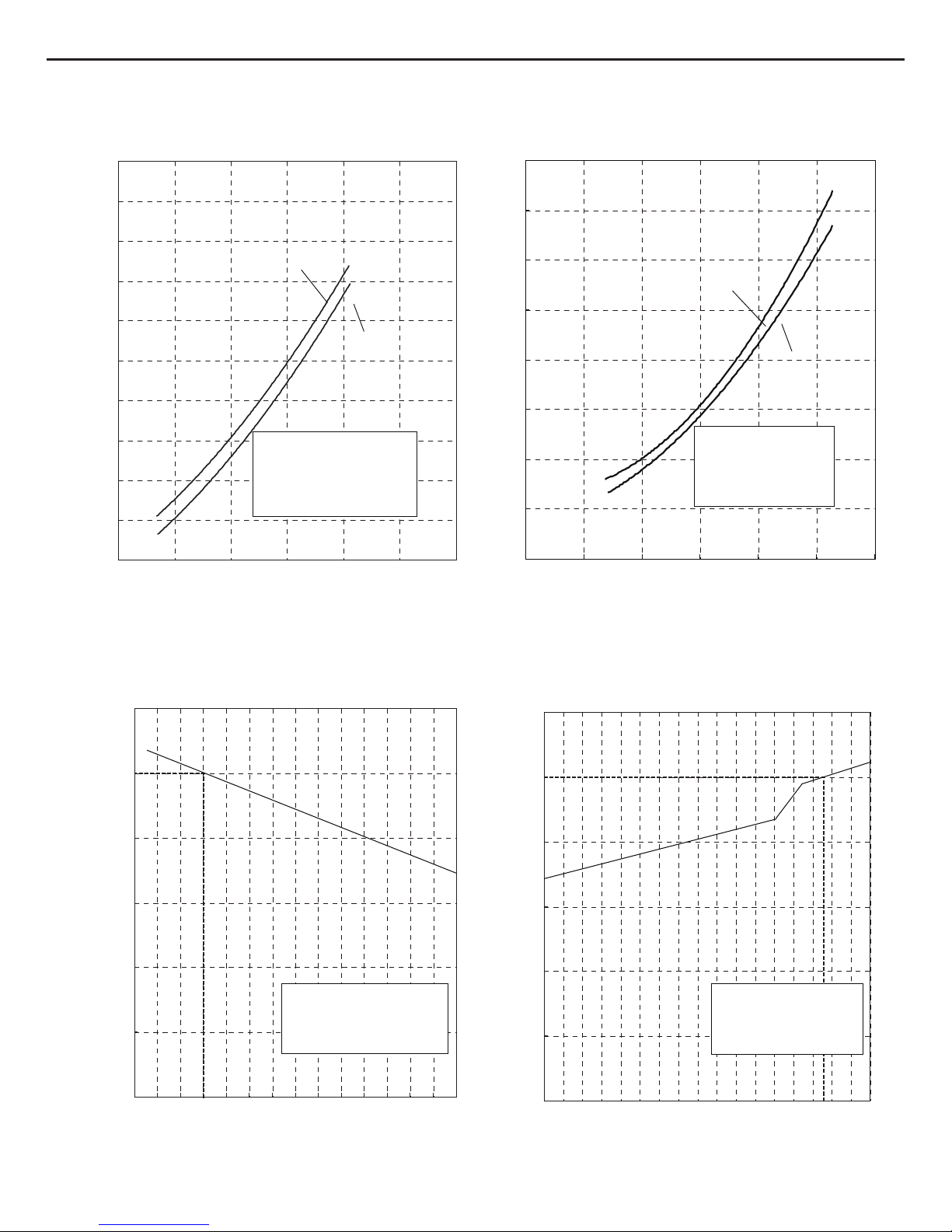
2.2 Operation Characteristic Curve
2.3 Capacity Variation Ratio According to Temperature
0
1
2
3
4
5
6
7
8
9
10
020406080100 120
Condition
Indoor:DB 27 WB19
Indoor air flow: Turbo
Pipe length:5m
Voltage:230V
Compressor Speed(rps)
0
1
2
3
4
5
6
7
8
020406080 100 120
Condition
Indoor:DB 20
Indoor air flow:Turbo
Pipe length:5m
Voltage:230V
Compressor Speed(rps)
Cooling
Heating
Current(A)
Current(A)
50
60
70
80
90
100
110
32 33 34 35 36 37 38 39 40 41 42 43 44 45 46
Capacity ratio(%)
Condition
Indoor:DB27 WB19
Indoor air flow:
Turbo
Pipe length:5m
Outdoor temp. (°C)
0
20
40
60
80
100
120
Capacity ratio(%)
Outdoor temp. (°C)
gnitaeHgnilooC
09K
12K
-7 -5 0510
Condition
Indoor:DB20
Indoor air flow:
Turbo
Pipe length:5m
°C °C
°C
°C °C
°C
09K
12K
5
Technical Information
Service Manual
2.4 Cooling and Heating Data Sheet in Rated Frequency
Rated cooling
condition(°C) (DB/WB)
Model
Pressure of gas pipe
connecting indoor and
outdoor unit
Inlet and outlet pipe
temperature of heat
exchanger
Fan speed of
indoor unit
Fan speed of
outdoor unit
Compressor
revolution (rps)
Indoor Outdoor P (MPa) T1 (°C) T2 (°C)
27/19 35/24
09K
0.9~1.1
12 to 15 65 to 38
TURBO High
54
12K 11 to 14 64 to 37 60
Rated heating
condition(°C) (DB/WB)
Model
Pressure of gas pipe
connecting indoor and
outdoor unit
Inlet and outlet pipe
temperature of heat
exchanger
Fan speed of
indoor unit
Fan speed of
outdoor unit
Compressor
revolution (rps)
Indoor Outdoor P (MPa) T1 (°C) T2 (°C)
20/- 7/6
09K
2.2~2.4
35 to 63 2 to 5
TURBO High
62
12K 35 to 65 2 to 5 66
Instruction:
T1: Inlet and outlet pipe temperature of evaporator
T2: Inlet and outlet pipe temperature of condenser
P: Pressure at the side of big valve
Connection pipe length: 5 m.
Cooling:
Heating:
Indoor side noise when blowing
Outdoor side noise when Compressor speed changed
Compressor Speed(rps)
706050403020
45
50
55
)
A(Bd
/
esioN
75
09K
12K
Indoor fan motor rotating speed
LowMiddleHighSupper High
25
30
35
40
45
)
A(Bd
/esioN
2.5 Noise Curve
Service Manual
3. Outline Dimension Diagram
3.1 Indoor Unit
3.2 Outdoor Unit
143 80
45
45
Φ55
Φ55
845
542
173
180
275
130
Unit:mm
320
776
510
714257
286
540
6
Technical Information
7
Service Manual
4. Refrigerant System Diagram
Cooling and heating model
Connection pipe specication:
Liquid pipe:1/4" (6mm)
Gas pipe:3/8" (9.52mm)
Indoor unit
Outdoor unit
Indoor unit
Outdoor unit
COOLING
HEATING
Accumlator
Accumlator
4-Way valve
COOLING
Discharge
Suction
Discharge
Suction
Heat
exchanger
(evaporator)
Heat
exchanger
(evaporator)
Heat
exchanger
(condenser)
Valve
Valve
Valve
Valve
Liquid pipe
side
Gas pipe
side
Liquid pipe
side
Gas pipe
side
Compressor
Strainer
StrainerStrainer
Electron
expansion
valve
Electron
expansion
valve
Compressor
Technical Information

Service Manual
5. Electrical Part
5.1 Wiring Diagram
● Indoor Unit
●Instruction
Symbol Symbol Color Symbol Symbol Color Symbol Name
WH White GN Green CAP Jumper cap
YE Yellow BN Brown COMP Compressor
RD Red BU Blue Grounding wire
YEGN Yellow/Green BK Black / /
VT Violet OG Orange / /
Note: Jumper cap is used to determine fan speed and the swing angle of horizontal lover for this model.
8
Technical Information
INDOOR UNIT
L1
L1
PE
PE
M1
M2
DISP1
DISP2
AP1
DISPLAY
13
BN:BROWN
BU:BLUE
BK:BLACK
YE:YELLOW
YEGN:YELLOW GREEN
PGF
PG
AC-L
ROOM TUBE
SWING-UD
SWING MOTOR(U.D)
FAN MOTOR
TEM.SENSOR
TUBE
ROOM
TEM.SENSOR
CAP
JUMP
RT2
RT1
θ
θ
COOL PLASMA
GENERATOR IS
OPTIONAL
.
COOL PLASMA
GENERATOR
~
EVAPORATOR
ELECTRIC BOX
BK
N
YEGN
YEGN
COM-OUT
3
2
N(1)
BN
BU
XT1
AP2
BU
RD
HEALTH-L
HEALTH-N
N
L
OUTDOOR
UNIT
XT
BU
BK
BN
YEGN
3
2
N(1)
TERMINAL
BLOCK
● Outdoor Unit
9
Technical Information
PE
POWER
PE
L
N
L
N
N(1)
2
3
XT
L
WH
OG
L3
E
W
V
U
LX1-1
LX1-2
OFAN
WVU
COMU
N
AC-L1
MID.ISOLATION SHEET
BOX
L2
PE
W19
W20
BU
BK
BN
RD
YEBU
YEGN
RD
YE
BU
COMP
FAN MOTOR
YEGN
YEGN
YEGN
L1
L1
AP2
PE
PE
M
COMP.
L4
ELECTRIC
HEAT2
EH2
HEATER
(CHASSIS)
HEAT1
(COMP)
HEATER
RDRD
EH1
RDRD
4WAY
4YV
θ
θ
θ
TEM.SENSOR
EXHAUST
OUTROOM
TEM.SENSOR
CN2
RT3
RT2
RT1
TEM.SENSOR
TUBE
L3
XT1
INDOOR
UNIT
TERMINAL
BLOCK
OUTDOOR UNIT
NOTE:
Motor
applies to the
iron shell motor.
ground only
CN1
EKV
The electrical
heaters are
optional.
3
2
N(1)
10
Technical Information
Service Manual
8
9
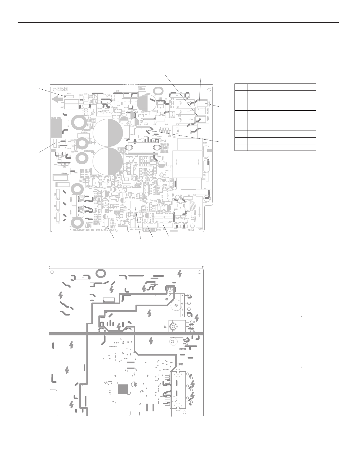
5.2 PCB Printed Diagram
Indoor Unit
●
Top view
●
Bottom view
1 Port of Live wire
2 Protective tube
3 Live wire of health function
4 Port of neutral wire
5 Port of indoor fan
6
7 Jumper Cap
8 Auto button
9 Feedback of indoor fan
10 Port of motor for vertical swing
11
Port of motor for horizontal
swing
12 Buzzer
13
Port of indoor ambient temp
14
Port of indoor pipe temp sensor
15
16 Main chip
17
Communication port
High-frequency transformer
2
3
4
5
10
11
7
13
14
12
6
15
Port of display
17
16
1
11
Technical Information
Service Manual
Outdoor Unit
●
Top view
●
Bottom view
1
2
3 4
5
6
7
1 inductance pin2
2 inductance pin1
3 four-wayvalve
4 compressor electricheater
5 chassis electric heater
6 fan neilsbed
7
8
electric expansion valve
9 main chip
10
temp. sensor
8
9
10
EEPROM
12
Technical Information
Service Manual
6. Function and Control
6.1 Remote Controller Introduction
Buttons on Remote Controller
Introduction for Icons on Display Screen
Introduction for Buttons on Remote Controller
1. ON/OFF Button
Press this button can turn on or turn off the air conditioner. After turning on the air conditioner, operation indicator " " on indoor
unit’s display is ON (green indicator. The colour is different for different models), and indoor unit will give out a sound.
2. MODE Button
Press this button to select your required operation mode.
Note:After putting through the power, the air conditioner will give out a sound. Operation indictor " " is ON (red indicator). After that,
you can operate the air conditioner by using remote controller.
AUTO COOL DRY FAN HEAT
2
3
6
8
11
13
14
1
7
4
5
9
10
12
15
ON/OFF button
MODE button
I FEEL button
+/- button
FAN button
button
button
button
CLOCK button
X-FAN button
(Note: X-FAN is the same with
BLOW)
TEMP button
TURBO button
LIGHT button
1
2
3
4
5
6
7
8
9
10
11
12
13
14
15
SLEEP button
TIMER ON/TIMER OFF button
operation mode
auto mode
cool mode
dry mode
fan mode
heat mode
clock
sleep mode
set fan speed
send signal
X-fan mode
ventilation operation
set temperature
turbo mode
set time
TIMER ON/TIMER
OFF
child lock
light
swing
Temp. display type
:set temp.
:outdoor ambient temp.
:indoor ambient
temp.
health function
I feel
13
Technical Information
Service Manual
4. FAN Button
Pressing this button can set fan speed circularly as: auto (AUTO), low( ) ,medium( ),high( ).
Note:
● Under AUTO speed, the IDU fan motor will adjust the fan speed (high, medium or low speed) according to ambient temperature.
● Fan speed under dry mode is low speed.
● When selecting auto mode, Air conditioner will start auto operation according to indoor ambient temperature.Set temperature can’t be
adjusted and will not be displayed as well. Press "FAN" button can adjust fan speed. Press " " button can adjust fan blowing angle.
● After selecting cool mode, air conditioner will operate under cool mode. Cool indicator " " on indoor unit is ON. Press "+" or "-" button
to adjust set temperature. Press "FAN" button to adjust fan speed. Press " " button to adjust fan blowing angle.
● When selecting dry mode, the air conditioner operates at low speed under dry mode. Dry indicator " " on indoor unit is ON. Under dry
mode, fan speed can’t be adjusted. Press " " button to adjust fan blowing angle.
● When selecting fan mode, the air conditioner will only blow fan, no cooling and no heating.All indicators are OFF.Operation indicator is
ON.Press "FAN" button to adjust fan speed. Press " " button to adjust fan blowing angle.
● When selecting heating mode, the air conditioner operates under heat mode. Heat indicator " " on indoor unit is ON. Press “+” or “-“
button to adjust set temperature Press “FAN” button to adjust fan speed. Press " " button to adjust fan blowing angle.(Cooling only unit
won’t receive heating mode signal. If setting heat mode with remote controller, press ON/OFF button can’t start up the unit).
Note:
● For preventing cold air, after starting up heating mode, indoor unit will delay 1~5minutes to blow air (actual delay time is depend on
indoor ambient temperature).
● Set temperature range from remote controller: 16~30℃ ; Fan speed: auto, low speed,medium speed, high speed.
3. “+” or“-” Button
● Press “+” or “-“ button once increase or decrease set temperature 1℃.Holding "+" or "-" button, 2s later, set temperature on remote
controller will change quickly. On releasing button after setting is nished, temperature indicator on indoor unit will change accordingly.
(Temperature can’t be adjusted under auto mode)
● When setting TIMER ON, TIMER OFF or CLOCK, press “+” or “-“ button to adjust time.(Refer to CLOCK, TIMER ON, TIMER OFF
buttons)
6. CLOCK Button
Press this button to set clock time. " " icon on remote controller will blink. Pess "+" or "-" button within 5s to set clock time. Each
pressing of "+" or "-" button, clock time will increase or decrease 1 minute. Hold "+" or "-" button, 2s later, time will change quickly.
Release this button when reaching your required time. Press “CLOCK" button to conrm the time. " " icon stops blinking.
Note:
● Clock time adopts 24-hour mode.
● The interval between two operation can’t exceeds 5s. Otherwise, remote controller will quit setting status. Operation for TIMER
ON/TIMER OFF is the same.
7. TIMER-ON/TIMER-OFF Button
● TIMER ON button
TIMER ON button
“TIMER ON” button can set the time for timer on. After pressing this button, " " icon disappears and the word “ON" on remote
5. Button
Pressing this button can select up&down swing angle. Fan blow angle can be selected circularly as below:
● When selecting " " , air conditioner is blowing fan automatically. Horizontal louver will automatically swing up & down at
maximum angle.
● When selecting "
、、
、、
", air conditioner is blowing fan at fixed position. Horizontal louver will stop at the fixed
position.
● When selecting "
、
、
”, air conditioner is blowing fan at xed angle. Horizontal louver will send air at the xed angle.
● Hold " " button above 2s to set your required swing angle. When reaching your required angle, release the button.
Note:
"
、
、
" may not be available. When air conditioner receives this signal, the air conditioner will blow fan automatically.
Auto
(horizontal louvers
stops at current position)
no display
14
Technical Information
Service Manual
controller blinks. Press "+" or "-"button to adjust TIMER ON setting. After each pressing "+" or "-"button, TIMER ON setting will increase
or decrease 1min. Hold "+" or "-"button, 2s later, the time will change quickly
until reaching your required time. Press “ TIMER ON”to conrm it. The word “ON" will stop blinking. " " icon resumes displaying.
Cancel TIMER ON: Under the condition that TIMER ON is started up, press “TIMER ON” button to cancel it.
● TIMER OFF button
"TIMER OFF" button can set the time for timer off. After pressing this button, " " icon disappears and the word "OFF" on remote
controller blinks. Press "+" or "-" button to adjust TIMER OFF setting. After each pressing "+" or "-" button, TIMER OFF setting will
increase or decrease 1min. Hold "+" or "-" button, 2s later, the time will change
quickly until reaching your required time. Press "TIMER OFF" to confirm it .The word "OFF"will stop blinking " " icon resumes
displaying. Cancel TIMER OFF. Under the condition that TIMER OFF is started up, press “TIMER OFF” button to cancel it.
Note:
● Under on and off status, you can set TIMER OFF or TIMER on simultaneously.
● Before setting TIMER ON or TIMER OFF, please adjust the clock time.
● After starting up TIMER ON or TIMER OFF, set the constant circulating valid. After that, air conditioner will be turned on or turned off
according to setting time. ON/OFF button has no effect on setting. If you don’t need this function, please use remote controller to cancel
it.
8. X-FAN Button
Press this button under cool and dry mode to start up x-fan function, and " " icon on remote controller will be displayed. Press this
button again to cancel x-fan function, and " "icon will disappear.
Note:
● When x-fan function is on, if the air conditioner is turned off, indoor fan will still operate at low speed for a while to blow the residual
water inside the air duct.
● During x-fan operation, press X-FAN button to turn off x-fan function. Indoor fan will stop operation immediately.
9. TEMP Button
By pressing this button, you can see indoor set temperature, indoor ambient temperature or outdoor ambient temperature on indoor
unit’s display. The setting on remote controlleris selected circularly as below:
When selecting " " or no display with remote controller, temperature indicator on indoor unit displays set temperature;
When selecting " " with remote controller, temperature indicator on indoor unit displays indoor ambient temperature;
When selecting " " with remote controller, temperature indicator on indoor unit displays outdoor ambient temperature.
Note:
● Outdoor temperature display is not available for some models. At that time, indoor unit receives" " signal, while it displays
indoor set temperature.
● It’s defaulted to display set temperature when turning on the unit.There is no display in the remote controller.
● Only for the models whose indoor unit has dual-8 display
10. TURBO Button
Under COOL or HEAT mode, press this button to turn to quick COOL or quick HEAT mode. " " icon is displayed on remote
controller. Press this button again to exit turbo function and " " icon will disappear.
11. SLEEP Button
Under COOL, HEAT mode, press this button to start up sleep function. " " icon is displayed on remote controller. Press this button
again to cancel sleep function and " " icon will disappear.
12. LIGHT Button
Press this button to turn off display light on indoor unit. " " icon on remote controller disappears. Press this button again to turn
on display light. " " icon is displayed.
Child lock function:
Press "+"and "-" simultaneously to turn on or turn off child lock function. When child lock function is on, " " icon is displayed on
remote controller. If you operate the remote controller, it won’t send signal.
Temperature display switchover function:
Under OFF status, press "-" and "MODE" buttons simultaneously to switch temperature display between °C and °F.
no display
Function Introduction for Combination Buttons
15
Technical Information
Service Manual
Note:
● During operation, point the remote control signal sender at the receiving window
on indoor unit.
● The distance between signal sender and receiving window should be no more than
8m, and there should be no obstacles between them.
● Signal may be interfered easily in the room where there is fluorescent lamp or
wireless telephone; remote controller should be close to indoor unit during operation.
● Replace new batteries of the same model when replacement is required.
● When you don’t use remote controller for a long time, please take out the batteries.
● If the display on remote controller is fuzzy or there’s no display, please replace
batteries.
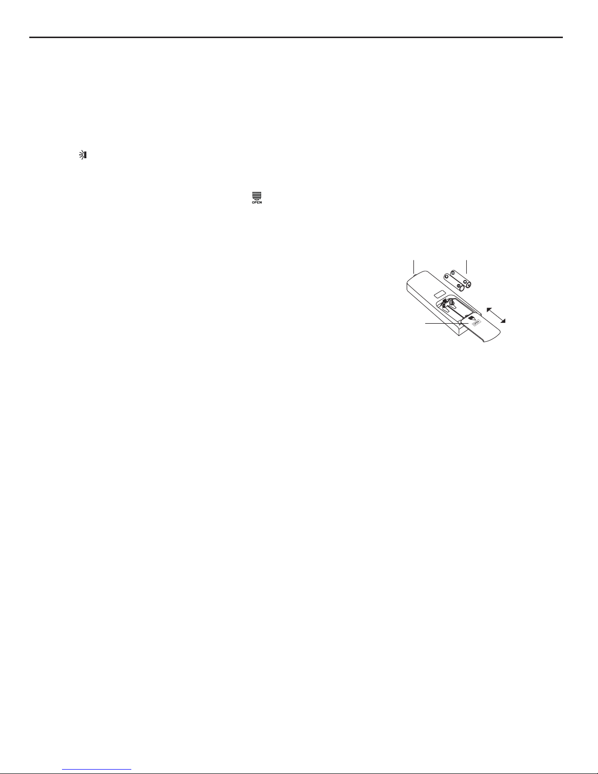
Signal sender
Battery
Cover of
battery box
Remove
Reinstall
1. After putting through the power, press “ON/OFF” button on remote controller to turn on
the air conditioner.
2. Press "MODE" button to select your required mode:AUTO,COOL,DRY,FAN,HEAT.
3. Press “+” or “-“ button to set your required temperature. (Temperature can’t be
adjusted under auto mode).
4. Press ‘FAN” button to set your required fan speed: auto, low, medium and high speed.
5. Press " " button to select fan blowing angle.
1.Press the back side of remote controller marked with“ ”as shown in the g, and then push out the cover
of battery box along the arrow direction.
2. Replace two 7# (AAA 1.5V) dry batteries, and make sure the position of “+” polar and “-“ polar are correct.
3. Reinstall the cover of battery box.
Operation Guide
Replacement of Batteries in Remote Controller
16
Technical Information
Service Manual
6.2 Brief Description of Modes and Functions
1. Temperature Parameters
Indoor preset temperature (T
preset
)
Indoor ambient temperature (T
amb.
)
2. Basic Functions
Once energized, in no case should the compressor be restarted within less than 3 minutes. In the situation that memory
function is available, for the first energization, if the compressor is at stop before de-energization, the compressor will be
started without a 3-minute lag; if the compressor is in operation before de-energization, the compressor will be started with
a 3-minute lag; and once started, the compressor will not be stopped within 6 minutes regardless of changes in room
temperature;
(2) Dehumidifying Mode
Working conditions and process of dehumidifying
If T
amb
.T
preset
, the unit will enter cooling and dehumidifying mode, in which case the compressor and the outdoor fan will
operate and the indoor fan will run at low speed.
If T
preset
-2 T
amb
.T
preset
, the compressor remains at its original operation state.
If T
amb
.< T
preset
-2 , the compressor will stop, the outdoor fan will stop with a time lag of 30s, and the indoor fan will
operate at low speed.
(1) COOL mode
The condition and process of cooling
If T
amb.≥Tpreset
COOL mode will act, the compressor and outdoor fan will run, and the indoor fan will run at the set
speed.
If T
amb.≤Tprese
t-2
, the compressor will stop, the outdoor fan will delay 30 seconds to stop, and the indoor fan will
run at the set speed.
If Tpreset-2 ≤T
amb
≤T
preset
, the unit will keep running in the previous mode.
In this mode, the reversal valve will not be powered on and the temperature setting range is 16 ~30.
Protection function
Overcurrent protection
If total current is high, the compressor will run in limited frequency. If total current is too high, the
compressor will stop, the
outdoor fan will delay 30 seconds to stop, indoor unit will display E5 and outdoor
yellow light will blink 5 times.
Antifreezing protection
When the antifreezing protection is detected, the compressor will stop, the outdoor fan will stop after 30 seconds, and the
indoor fan and swing motor will keep running in the original mode. When antifreezing protection is eliminated and the
compressor has stopped for 3 minutes, the compressor will resume running in the original mode.
Protection
Protection is the same as that under the cooling mode.
During antifreeze protection
Compressor
Outdoor fan
Indoor fan
min
Preset speed
Run Stop
Tpreset
Tpreset –2 ˚C
Compressor
Outdoor fan
Indoor fan
Run
Tamb.
Stop
Stop cooling
Start cooling
Original operating status
≥ 6 min. ≥ 3 min. ≥ 6 min.
Setting fan speed

17
Technical Information
Service Manual
(3) HEAT Mode
①
Working conditions and process of heating
If Tamb.≤Tpreset +2°C, the unit enters heating mode, in which case the four-way valve, the compressor and the outdoor fan will
operate simultaneously, and the indoor fan will run at preset speed in the condition of preset cold air prevention.
If T amb.≥Tpreset +5°C, the compressor will stop, the outdoor fan will stop with a time lag of 30s, and the indoor fan will stop after
60-second blow at low speed
If Tpreset +2°C<T amb.< Tpreset +5°C, the unit will maintain its original operating status.
Under this mode, the four-way valve is energized and temperature can be set within a range of 16 - 30°C. The operating symbol, the
heating symbol and preset temperature are revealed on the display.
②
Condition and process of defrost
When duration of successive heating operation is more than 45 minutes, or accumulated heating time more than 90 minutes, and
one of the following conditions is reached, the unit will enter the defrost mode after 3 minutes.
(1). T outdoor ambient
>
5°C, T outdoor tube≤-2°C;
(2) -2°C≤T outdoor ambient<5°C, T outdoor tube≤-6°C;
(3) -5°C≤T outdoor ambient<-2°C, T outdoor tube≤-8°C;
(4)-10°C≤T outdoor ambient<-5°C, T outdoor tube-T compensatory ≤ (T outdoor ambient-3°C)
(5)T outdoor ambient<-10°C, T outdoor tube-T compensatory ≤ (T outdoor ambient-3°C)
(after energizing, T compensatory=0°C during the first defrosting; if it is not the first defrosting, T compensatory is confirmed by
T outdoor tube of quitting last defrosting: a. when T outdoor tube>2°C, T compensatory=0°C; b. when T outdoor tube ≤ 2°C, T
compensatory=3°C)
At that time, the indoor fan stops and the compressor stops, and after 30 seconds the outer fan will stop, and then after 30 seconds,
the four-way valve will stop. After 30 seconds, the compressor is initiated for raising the frequency to defrost frequency.
When the compressor has operated under defrost mode for 7.5 minutes, or T outdoor ambient
≥
10°C, the compressor will be
converted to 46Hz operation. After 30 seconds, the compressor will stop. And after another 30 seconds, the four-way valve will
be opened, and after 60 seconds, the compressor and the outer fan will be started, the indoor fan will run under preset cold air
prevention conditions, and H1 will be displayed at temperature display area on the display panel. Defrost frequency is 85Hz.
③
Protection
◆
Cold air prevention
The unit is started under heating mode (the compressor is ON):
①
In the case of T indoor amb. <24°C: if T tube≤40°C
and the indoor fan is at stop state, the indoor fan will begin to run at low speed
with a time lag of 2 minutes. Within 2 minutes, if T tube>40°C, the indoor fan also will run at low speed; and after 1-minute operation
at low speed, the indoor fan will be converted to operation at preset speed. Within 1-minute low speed operation or 2-minute non-
operation, if T tube>42°C, the fan will run at present speed.
②
In the case of T indoor amb. ≥24°C: if T tube≤42°C, the indoor fan will run at low speed, and after one minute, the indoor fan will
be converted to preset speed. Within one-minute low speed operation, if T tube>42°C, the indoor fan will be converted to preset
speed.
Note: T indoor amb. indicated in
①
and
②
refers to, under initially heating mode, the indoor ambient temperature before the
command to start the compressor is performed according to the program, or after the unit is withdrawn from defrost, the indoor
ambient temperature before the defrost symbol is cleared.
◆
Total current up and frequency down protection
If the total current Itotal≤6A, frequency rise will be allowed; if Itotal≥7A, frequency rise will not be allowed; if Itotal≥8A, the compressor
will run at reduced frequency; and if Itotal≥9A, the compressor will stop and the outdoor fan will stop with a time lag of 30s.
(4) Fan Mode
Under the mode, the indoor fan will run at preset speed and the compressor, the outdoor fan, the four-way valve and the electric
heater will stop.
Under the mode, temperature can be set within a range of 16 - 30°C .
(5) AUTO Mode
①
Working conditions and process of AUTO mode
a. When T ambient ≥26°C, the unit will operate in Cool mode. The set temperature is 25°C.
b. When T ambient ≤22°C, the heat pump unit will operate in Heat mode., set temperature be 20°C; the cooling only unit will operate
in Fan mode, set temperature be 25°C.
c. When 23°C≤T ambient ≤25°C, the unit will operate in the previous state. If it is energized for the rst time, it will operate in Fan
mode.
d. Under auto mode, if its cooling mode, operation frequency is same as that under cooling mode; if its heating mode, operation
frequency is same as that under heating mode.

18
Technical Information
Service Manual
②
Protection
a. In cooling operation, protection is the same as that under the cooling mode;
b. In heating operation, protection is the same as that under the heating mode;
c. When ambient temperature changes, operation mode will be converted preferentially. Once started, the compressor will
remain unchanged for at least 6 minutes.
(6) Common Protection Functions and Fault Display under COOL, HEAT, DRY and AUTO Modes
①
Overload protection
T tube: measured temperature of outdoor heat exchanger under cooling mode; and measured temperature of indoor heat exchanger
under heating mode.
1) Cooling overload
a. If T tube≤52°C, the unit will return to its original operation state.
b. If T tube≥55°C, frequency rise is not allowed.
c. If T tube≥58°C, the compressor will run at reduced frequency.
d. If T tube≥62°C, the compressor will stop and the indoor fan will run at preset speed.
2) Heating overload
a. If T tube≤50°C, the unit will return to its original operation state.
b. If T tube≥53°C, frequency rise is not allowed.
c. If T tube≥56°C, the compressor will run at reduced frequency.
d. If T tube≥60°C, the compressor will stop and the indoor fan will blow residue heat and then stop.
②
Exhaust temperature protection of compressor
If exhaust temperature ≥98°C, frequency is not allowed to rise.
If exhaust temperature ≥103°C, the compressor will run at reduced frequency.
If exhaust temperature ≥110°C, the compressor will stop.
If exhaust temperature ≤90°C and the compressor has stayed at stop for at least 3 minutes, the compressor will resume its operation.
③
Communication fault
If the unit fails to receive correct signals for durative 3 minutes, communication fault can be justied and the whole system will stop.
④
Module protection
Under module protection mode, the compressor will stop. When the compressor remains at stop for at least 3 minutes, the
compressor will resume its operation. If module protection occurs six times in succession, the compressor will not be started again.
⑤
Overload protection
If temperature sensed by the overload sensor is over 115°C, the compressor will stop and the outdoor fan will stop with a time lag of
30 seconds. If temperature is below 95°C, the overload protection will be relieved°C.
⑥
DC bus voltage protection
If voltage on the DC bus is below 150V or over 420V, the compressor will stop and the outdoor fan will stop with a time lag of 30
seconds. When voltage on the DC bus returns to its normal value and the compressor has stayed at stop for at least 3 minutes, the
compressor will resume its operation.
⑦
Faults of temperature sensors
3. Other Controls
(1) ON/OFF
Press the remote button ON/OFF: the on-off state will be changed once each time you press the button.
(2) Mode Selection
Press the remote button MODE, then select and show in the following ways: AUTO, COOL, DRY, FAN, HEAT, AUTO.
(3) Temperature Setting Option Button
Each time you press the remote button TEMP+ or TEMP-, the setting temperature will be up or down by 1°C. Regulating
Range: 16~30°C, the button is useless under the AUTO mode.
(4) Time Switch
You should start and stop the machine according to the setting time by remote control.
(5) SLEEP State Control
1. In cooling mode:
1.1 When the initial set temperature is 16-23°C,the temperature will rise 1°C by every hour after sleep function is set; the temperature
will not change after rising 3°C; after running for 7 hours, the temperature will decrease 1°C and it will not change after that.
19
Technical Information
Service Manual
1.2 When the initial set temperature is 24-27°C,the temperature will rise 1°C by every hour after sleep function is set; the temperature
will not change after rising 2°C;after running for 7 hours, the temperature will decrease 1°C and it will not change after that.
1.3 When the initial set temperature is 28-29°C,the temperature will rise 1°C by every hour after sleep function is set; the temperature
will not change after rising 1°C; after running for 7 hours, the temperature will decrease 1°C and it will not change after that.
1.4 When the initial set temperature is 30°C, the unit will keep on running at this temperature; after running for 7 hours, the
temperature will decrease 1°C and it will not change after that.
Relationship between set temperature and running time:
2. In heating mode:
2.1 When the initial set temperature is 16°C, the unit will keep on running at this temperature;
2.2 When the initial set temperature is 17-20°C, the temperature will decrease 1°C by every hour after sleep function is set; the
temperature will not change after decreasing 1°C;
2.3 When the initial set temperature is 21-27°C, the temperature will decrease 1°C by every hour after sleep function is set; the
temperature will not change after decreasing 2°C;
2.4 When the initial set temperature is 28-30°C, the temperature will decrease 1°C by every hour after sleep function is set; the
temperature will not change after decreasing 3°C;
Relationship between set temperature and running time:
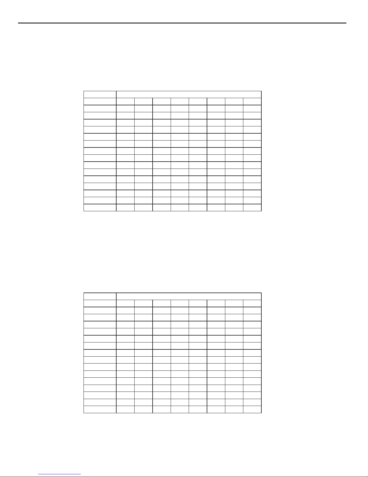
(6) Indoor Fan Control
The Indoor Fan can be set as HIGH, MED, LOW by remote control, and the Indoor Fan will be respectively run at high, medium, low
speed. It will also be set as AUTO, and the Indoor Fan is as the followings at the automatic wind speed.
Initial Temp. Running time(T)
0(start) 1 2 3 4 5 6 7 8
16 16 16 16 16 16 16 16 16
17 16 16 16 16 16 16 16 16
18 17 17 17 17 17 17 17 17
19 18 18 18 18 18 18 18 18
20 19 19 19 19 19 19 19 19
21 20 19 19 19 19 19 19 19
22 21 20 20 20 20 20 20 20
23 22 21 21 21 21 21 21 21
24 23 22 22 22 22 22 22 22
25 24 23 23 23 23 23 23 23
26 25 24 24 24 24 24 24 24
27 26 25 25 25 25 25 25 25
28 27 26 25 25 25 25 25 25
29 28 27 26 26 26 26 26 26
30 29 28 27 27 27 27 27 27
Initial Temp. Running time(T)
0(start) 1 2 3 4 5 6 7 8
16 17 18 19 19 19 19 18 18
17 18 19 20 20 20 20 19 19
18 19 20 21 21 21 21 20 20
19 20 21 22 22 22 22 21 21
20 21 22 23 23 23 23 22 22
21 22 23 24 24 24 24 23 23
22 23 24 25 25 25 25 24 24
23 24 25 26 26 26 26 25 25
24 25 26 26 26 26 26 25 25
25 26 27 27 27 27 27 26 26
26 27 28 28 28 28 28 27 27
27 28 29 29 29 29 29 28 28
28 29 29 29 29 29 29 28 28
29 30 30 30 30 30 30 29 29
30 30
30 30
30
30 30
29
29
20
Technical Information
Service Manual
①
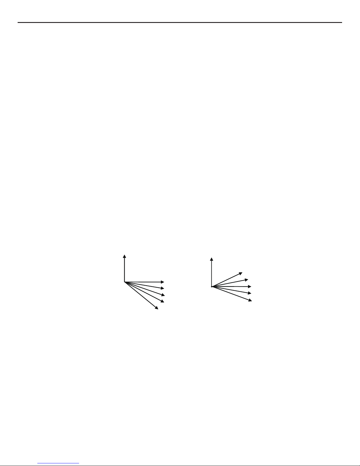
Cooling mode: in auto cooling mode or normal cooling mode, the auto fan speed will run at below mode:
a. When Tamb.≥Tpreset+2°C, the indoor fan will run at high speed;
b. When Tpreset<Tamb.<Tpreset+2°C, the indoor fan will run at middle speed;
c. Tamb.≤Tpreset, the indoor fan will run at low speed;
Switches between high speed and middle speed, middle speed and low speed, high speed and low speed, running time of 3.5
minutes must be ensured.
②
Heating mode: in auto heating mode or normal heating mode, the auto fan speed will run at below mode:
a. When Tamb.≤Tpreset+1°C, the indoor fan will run at high speed;
b. When Tpreset+1°C<Tamb.<Tpreset+3°C, the indoor fan will run at middle speed;
c. Tamb. ≥Tpreset+3°C, the indoor fan will run at low speed;
Switches between high speed and middle speed, middle speed and low speed, high speed and low speed, running time of 3.5
minutes must be ensured.
Fan mode is the same as cooling mode.
(7) Buzzer Control
The buzzer will send a “Di” sound when the air conditioner is powered up or received the information sent by the remote control or
there is a button input, the single tube cooler doesnt receive the remote control ON signal under the mode of heating mode.
(8) Auto button
If the controller is on, it will stop by pressing the button, and if the controller is off, it will be automatic running state by pressing the
button, swing on and light on, and the main unit will run based on the remote control if there is remote control order.
(9) Up-and-Down Swinging Control
When power on, the up-and-down motor will rstly move the air deector to counter-clockwise, close the air outlet. After starting the
machine, if you dont set the swinging function, heating mode and auto-heating mode, the up-and-down air deector will move to
D clockwise; under other modes, the up-and-down air deector will move to L1. If you set the swinging function when you start the
machine, then the wind blade will swing between L and D. The air deector has 7 swinging states: Location L, Location A, Location
B, Location C, Location D, Location L to Location D, stop at any location between L-D (the included angle between L~D is the same).
The air deector will be closed at 0 Location, and the swinging is effectual only on condition that setting the swinging order and the
inner fan is running. The indoor fan and compressor may get the power when air deector is on the default location.
(10) Display
①
Operation pattern and mode pattern display
All the display patterns will display for a time when the power on, the operation indication pattern will display in red under standby
status. When the machine is start by remote control, the indication pattern will light and display the current operation mode (the mode
light includes: Cooling, heating and dehumidify). If you close the light key, all the display patterns will close.
②
Double-8 display
According to the different setting of remote control, the nixie light may display the current temperature (the temperature scope is from
16°C to 30°C) and indoor ambient temperature. The set temperature displayed in auto cooling and fan mode is 25°C and the set
temperature displayed in auto heating mode is 20°C. Under heating mode, nixie tube displays H1 or heating indicator is off 0.5s and
blinks 10s in defrosting.(If you set the fahrenheit temperature display, the nixie light will display according to fahrenheit temperature)
(11) Protection function and failure display
E2: Freeze-proong protection E4: Exhausting protection E5: Overcurrent protection
E6: Communication failure E8: Overload protection
F1: Indoor ambient sensor start and short circuit (continuously measured failure in 5S)
A
L
B
C
D
O(0
R
)
O(0 )
L1
A1
B1
C1
D1
heating angle
cooling angle
R
F2: Indoor evaporator sensor start and short circuit (continuously measured failure in 5S)
F3: Outdoor ambient sensor start and short circuit (continuously measured failure in 30S)

F4: Outdoor condenser sensor start and short circuit (continuously measured failure in 30S, and do nt measure within 10 minutes
after defrosted)
F5: Outdoor exhausting sensor start and short circuit (continuously measured failure in 30S after the compressor operated 3
minutes)
H3: Overload protection of compressor H5: Module protection
PH: High-voltage protection PL: Low-voltage protection
P1: Nominal cooling and heating P2: Maximum cooling and heating
P3: Medium cooling and heating P0: Minimum cooling and heating
(12) Drying Function
You may start or stop the drying function under the modes of cooling and dehumidify at the starting status (The modes of
automatism, heating and air supply do not have drying function). Whe n you start the drying function, after stop the machine by
pressing the switch button, you should keep running the inner fans for 2 minutes und er low air damper (The s wing will operate a s
the former status within 2 minutes, cooling indicator is on for 0.5s and then off for 10s in drying and other load is stopped), then
stop the entire machine; When you stop the drying function, press the switch button will stop the machine directl y. When you start
the drying function, operating the drying button will stop the inner fans and close the guide louver.
(13) Memory function when interrupting the power supply
Memory content: mode, swing function, light, set temperature and wind speed. After interrupted the power supply, the mach ine
will start when recovering the power according to the memory content automatical ly. If the last remote control command has not
set the timed function, the system will remember the last remote control command and operate according it. If the last remote
control command has set timed function and the power supply is interrupted before the timed time, the system will remember the
timed function of the last remote control command, the timed time will recounted form power on. If the last remote control
command has set timed function, the time is out and the system is start or stop according to the set time when the power supply
is interrupted, the system will remember the operation status before the power supply was interrupted, and do not carry out timed
action; The timed clock will not remembered.
(14)Electric heating band control of outdoor unit
①Compressor electric heating band control:
a) Start condition: the compressor is in off status and the outdoor ambient temperature≤-5°C.
b) Stop condition: the band is off when either of the below condition is met:
1. The compressor is in on status;
2.The compressor is in off status and the outdoor ambient temperature≥-5°C.
c) When outdoor ambient temperature sensor is in malfunction status, the electric heating band stops operation.
②Condenser electric heating band control:
1.When Toutdoor ambient≤1°C, the electric heating band starts working;
2. When enter defrosting and defrosting is finished, the chassis electric heating band starts working for 3min as the compressor
starts. After the compressor starts for 3min and Toutdoor ambient≥3°C, the electric heating band stops operation.
3.When Toutdoor ambient≥3°C, the condenser electric heating band doesn ’t work.
4.When 1°C<Toutdoor ambient<3°C, the condenser electric heating band keeps the previous status.
When outdoor ambient temperature sensor is in malfunction status, the electric heating band stops operation; the electric heating
band can work again after 2min of last stop.
(15)Compulsive defrosting function
1.Condition of entering compulsive defrosting function;
When the unit and remote controller are set in heating mode and the set temperature is 16°C,continuously pressing
“+,-,+,-,+,-”button within 5s,the indoor unit will enter compulsi ve defrosting setting and indoor unit will send compulsive defrosting
signal to outdoor unit. When the outdoor unit receives compulsiv e defrosting signal,it will operate in normal defrosting mode.
When the indoor unit receives the information that outdoor unit has entered defrosting,it will cancel se nding com pulsiv e defrosting
signal to outdoor unit.Heating indicator on indoor unit is off for 0.5s and then blinks for 10s.
2.Condition of exiting compulsive defrosting function:
The condition of exiting compulsive defrosting function is the sam e as that in normal defrosting;after finishing defrosting,outdoor
unit will send the signal of normal operation mode to indoor unit and when the indoor unit receives the signal,it will operate in
normal mode.
(16)Refrigerant recycling function
1.Condition of entering refrigerant recycling function:
Within 5min of energizing,turning on the unit in cooling mode of 16°C,continuously press light button for 3 times within 3s to enter
refrigerant recycling mode;Fo is displayed and send refrigerant recycling signal to outdo or unit.
2.Condition of exiting refrigerant recycling mode:
After entering refrigerant recycling mode,when receive any remote control signal or enter refrigerant recycling mode for 25min,the
unit will exit refrigerant recycling mode.
Operation after refrigerant recycling mode:indoor unit runs in cooling mode,fan speed is super high,set temperature 16°C and the
horizontal louver opens to the min angle.
Operation after exiting refrigerant recycling mode:indoor unit will run is the set status of last time.
Service Manual
21
Technical Information
 Loading...