

Gree GWC09MA-K3NND3D, GWC09MA-K3NNA4F, GWC09MA-K3NNC9D, GWC09MA-K3NNA3D, GWH09MA-K3NNA4G Service Manual
...
GREE ELECTRIC APPLIANCES,INC.OF ZHUHAI
Change for Life
Service Manual
Models:
GWC09MA-K3NNA3D
GWC09MA-K3NNC3D
GWC09MA-K3NNC9D
GWC09MA-K3NND3D
GWC09MA-K3NNA4F
GWH09MA-K3NNA4G
GWC09MA-K3NNA5F
GWH09MA-K3NNA5F
GWC09MA-K3NNA9F
GWH09MA-K3NNA9F
GWC09MA-K3NNB3F
GWH09MA-K3NNB3F
(Refrigerant R410A)

Service Manual
Technical Information
Table of Contents
Part
Ⅰ
: Technical Information
.......................................................................1
1. Summary
......................................................................................................................1
2. Specications
..........................................................................................................3
2.1 Specication Sheet ...........................................................................................................3
2.2 Capacity Curve in Different Outdoor Temperature ...........................................................9
2.3 Cooling and Heating Data Sheet in Rated Frequency .....................................................9
3. Outline Dimension Diagram
......................................................................10
3.1 Indoor Unit ......................................................................................................................10
3.2 Outdoor Unit ................................................................................................................... 11
4. Refrigerant System Diagram
....................................................................12
5. Electrical Part
.........................................................................................................14
5.1 Wiring Diagram ...............................................................................................................14
5.2 PCB Printed Diagram .....................................................................................................17
6. Function and Control
......................................................................................18
6.1 Remote Controller Introduction .....................................................................................18
6.2 Brief Description of Modes and Functions ......................................................................22
Part
Ⅱ
: Installation and Maintenance
.................................................27
7. Notes for Installation and Maintenance
..........................................27
8. Installation
................................................................................................................29
8.1 Installation Dimension Diagram ......................................................................................29
8.2 Installation Parts-checking ............................................................................................31
8.3 Selection of Installation Location ....................................................................................31
8.4 Requirements Forelectric Connection ............................................................................31
8.5 Installation of Indoor Unit ................................................................................................31
8.6 Installation of Outdoor Unit .............................................................................................34
8.7 Vacuum Pumping and Leak Detection ...........................................................................35
8.8 Check after Installation and Test Operation ...................................................................35

Service Manual
Technical Information
9. Maintenance
............................................................................................................36
9.1 Error Code ......................................................................................................................36
9.2 Procedure of Troubleshooting ........................................................................................37
9.3 Maintenance Method for Normal Malfunction .................................................................42
10. Exploded View and Parts List
..............................................................44
10.1 Indoor Unit ....................................................................................................................44
10.2 Outdoor Unit .................................................................................................................51
11. Removal Procedure
.......................................................................................55
11.1 Removal Procedure of Indoor Unit ...............................................................................55
11.2 Removal Procedure of Outdoor Unit ............................................................................60
Appendix:
........................................................................................................................68
Appendix 1: Reference Sheet of Celsius and Fahrenheit ....................................................68
Appendix 2: Conguration of Connection Pipe .....................................................................68
Appendix 3: Pipe Expanding Method ...................................................................................69
Appendix 4: List of Resistance for Temperature Sensor ......................................................70
1
Technical Information
Service Manual
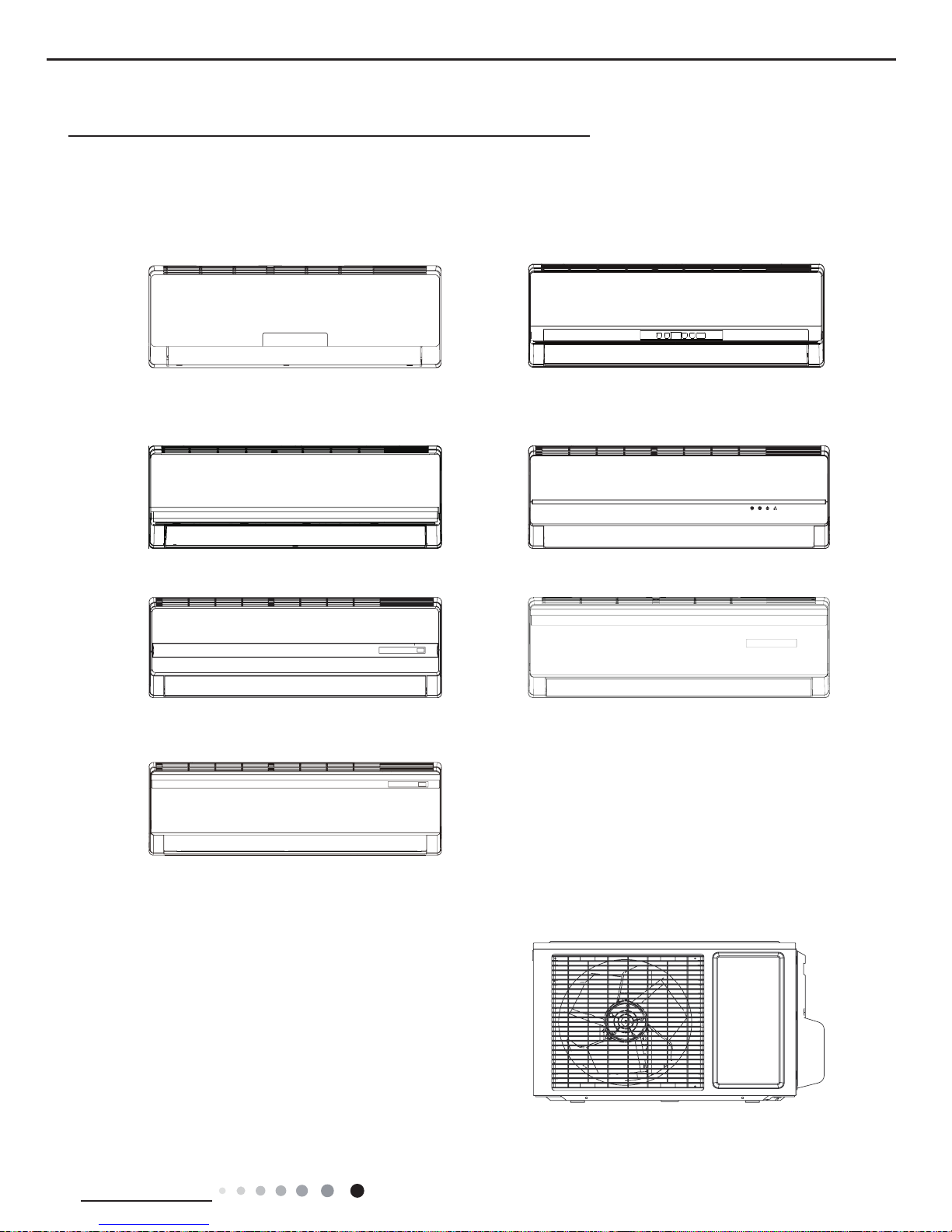
1. Summary
Indoor Unit:
GWC09MA-K3NNA3D/I
GWC09MA-K3NNA5F/I
GWH09MA-K3NNA5F/I
GWC09MA-K3NNB3F/I
GWH09MA-K3NNB3F/I
GWC09MA-K3NNA9F/I
GWH09MA-K3NNA9F/I
GWC09MA-K3NNC3D/I
GWC09MA-K3NNA4F/I
GWH09MA-K3NNA4G/I
GWC09MA-K3NND3D/I
Part
Ⅰ
: Technical Information
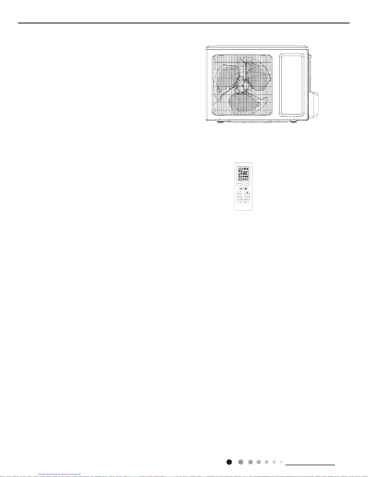
Outdoor Unit:
GWC09MA-K3NNE1D/O
GWC09MA-K3NNA5F/O
2
Technical Information
Service Manual
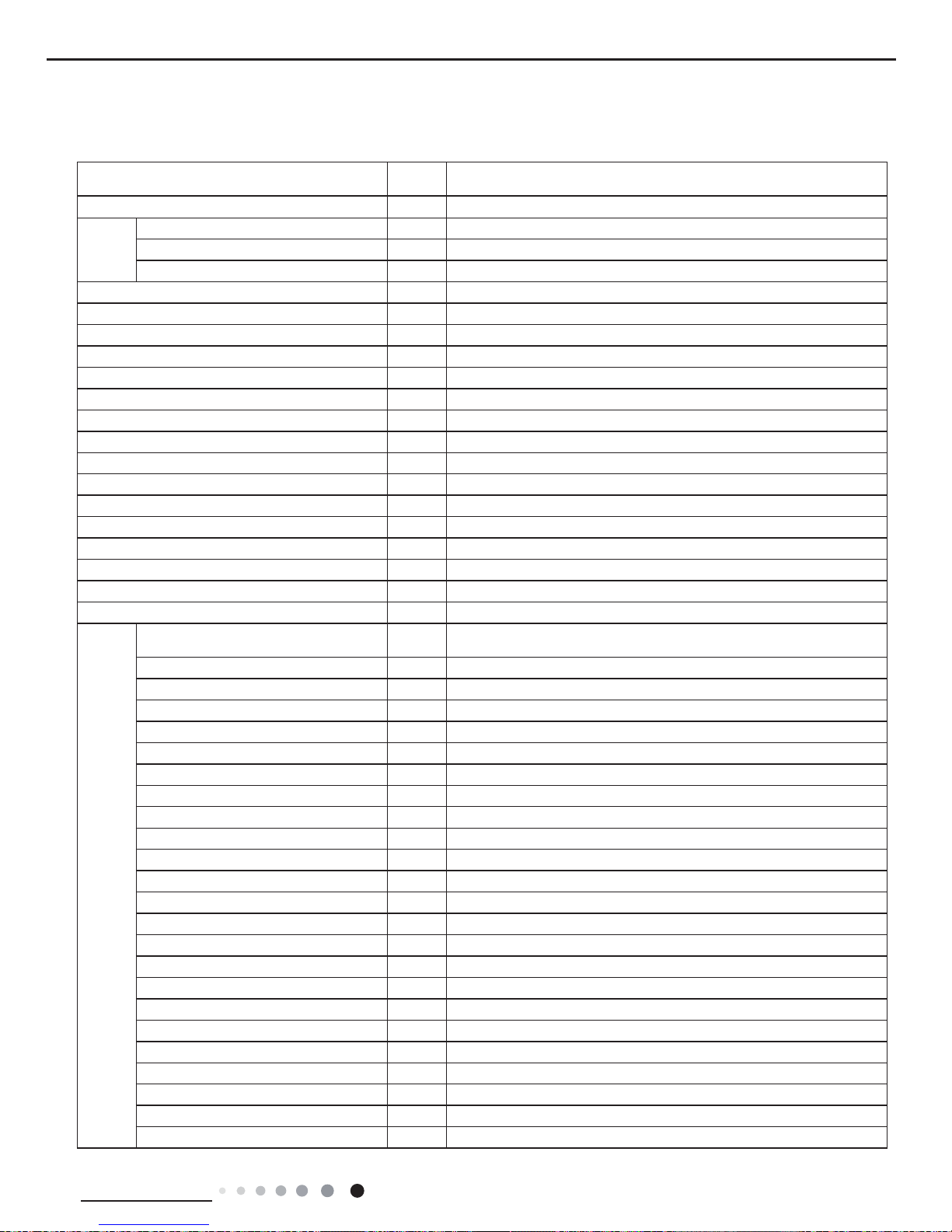
Remote Controller:
YB1FA(MOTO)
ON OFF/
MODE
FA
N
CLOCKTIMER
ON
X-FANTEMP
TIMEROFF
TURBOSLEEP LIGHT
GWH09MA-K3NNA5F/O
3
Technical Information
Service Manual
2. Specications
2.1 Specication Sheet
Model
1.GWC09MA-K3NNA3D 2.GWC09MA-K3NNC3D
3.GWC09MA-K3NND3D 4.GWC09MA-K3NNC9D
Product Code 1.CA171023901 2.CA136010001 3.CA405009001 4.CA145006701
Power
Supply
Rated Voltage V
~
220-240
Rated Frequency Hz 50
Phases 1
Power Supply Mode Indoor
Cooling Capacity W 2600
Heating Capacity W /
Cooling Power Input W 920
Heating Power Input W /
Cooling Power Current A 4.27
Heating Power Current A /
Rated Input W 1200
Rated Current A 5.57
Air Flow Volume(SH/H/M/L/SL)
m3/h
500/440/370/300/-
Dehumidifying Volume
L/h 0.8
EER
W/W 2.83
COP
W/W /
SEER W/W /
HSPF W/W /
Application Area m
2
12-18
Indoor
Unit
Model of indoor unit
1.GWC09MA-K3NNA3D/I 2.GWC09MA-K3NNC3D/I
3.GWC09MA-K3NND3D/I 4.GWC09MA-K3NNC9D/I
Indoor Unit Product Code 1.CA171N23901 2.CA136N10000 3.CA405N09000 4.CA145N06700
Fan Type Cross-ow
Diameter Length(DXL) mm Φ85X596
Fan Motor Cooling Speed(SH/H/M/L/SL) r/min 1260/1050/920/730/-
Fan Motor Heating Speed(SH/H/M/L/SL) r/min /
Output of Fan Motor W 10
Fan Motor RLA A 0.1
Fan Motor Capacitor μF 1
Input of Heater W /
Evaporator Form Aluminum Fin-copper Tube
Pipe Diameter mm Φ7
Row-n Gap mm 2-1.5
Coil Length (LXDXW) mm 581X25.4X264
Swing Motor Model MP24AA
Output of Swing Motor W 1.5
Fuse A 3.15
Sound Pressure Level (SH/H/M/L/SL) dB (A) 39/36/33/30/-
Sound Power Level (SH/H/M/L/SL) dB (A) 49/46/43/40/-
Dimension (WXHXD) mm 790X265X174
Dimension of Carton Box (LXWXH) mm 870X248X355
Dimension of Package(LXWXH) mm 873X251X370
Net Weight kg 9
Gross Weight kg 12/11.5/11.5/10.5
4
Technical Information
Service Manual
The above data is subject to change without notice; please refer to the nameplate of the unit.
Outdoor
Unit
Model of Outdoor Unit GWC09MA-K3NNE1D/O
Outdoor Unit Product Code CA143W04901
Compressor Manufacturer/Trademark ZHUHAI LANDA COMPRESSOR CO.,LTD.
Compressor Model QXA-B102C130
Compressor Oil RB68EP
Compressor Type Rotary
L.R.A. A 17
Compressor RLA A 3.9
Compressor Power Input W 850
Overload Protector Internal
Throttling Method Capillary
Operation Temp
℃
16~30
Ambient Temp (Cooling)
℃
18~43
Ambient Temp (Heating)
℃
/
Condenser Form Aluminum Fin-copper Tube
Pipe Diameter mm Φ7
Rows-n Gap mm 1-1.4
Coil Length (LXDXW) mm 666X12.7X400
Fan Motor Speed
rpm 950
Output of Fan Motor W 20
Fan Motor RLA A 0.37
Fan Motor Capacitor μF 1.5
Air Flow Volume of Outdoor Unit m3/h 1200
Fan Type Axial-ow
Fan Diameter mm Φ320
Defrosting Method /
Climate Type T1
Isolation I
Moisture Protection IP24
Permissible Excessive Operating
Pressure for the Discharge Side
MPa 4.3
Permissible Excessive Operating
Pressure for the Suction Side
MPa 2.5
Sound Pressure Level (H/M/L) dB (A) 50/-/-
Sound Power Level (H/M/L) dB (A) 60/-/-
Dimension (WXHXD) mm 720X428X310
Dimension of Carton Box (LXWXH) mm 765X350X475
Dimension of Package(LXWXH) mm 768X353X490
Net Weight kg 25
Gross Weight kg 29
Refrigerant R410A
Refrigerant Charge kg 0.56
Connection
Pipe
Length m 5
Gas Additional Charge g/m 15
Outer Diameter Liquid Pipe mm Φ6
Outer Diameter Gas Pipe mm Φ9.52
Max Distance Height m 10
Max Distance Length m 15
Note: The connection pipe applies metric diameter.
5
Technical Information
Service Manual
Model
1.GWC09MA-K3NNA4F 2.GWC09MA-K3NNA5F
3.GWC09MA-K3NNA9F 4.GWC09MA-K3NNB3F
Product Code 1.CA161012900 2.CA162017700 3.CA182006000 4.CA163013000
Power
Supply
Rated Voltage V
~
220-240
Rated Frequency Hz 50
Phases 1
Power Supply Mode Indoor
Cooling Capacity W 2650
Heating Capacity W /
Cooling Power Input W 803
Heating Power Input W /
Cooling Power Current A 3.65
Heating Power Current A /
Rated Input W /
Rated Current A 5.33
Air Flow Volume(SH/H/M/L/SL) m3/h 500/450/400/350/-
Dehumidifying Volume L/h 0.8
EER W/W 3.3
COP
W/W /
SEER W/W /
HSPF W/W /
Application Area m
2
12-18
Indoor
Unit
Model of indoor unit
1.GWC09MA-K3NNA4F/I 2.GWC09MA-K3NNA5F/I
3.GWC09MA-K3NNA9F/I 4.GWC09MA-K3NNB3F/I
Indoor Unit Product Code 1.CA161N12900 2.CA162N17700 3.CA182N06000 4.CA163N13000
Fan Type Cross-ow
Diameter Length(DXL) mm Φ85X596
Fan Motor Cooling Speed(SH/H/M/L/SL) r/min 1350/1150/980/750/-
Fan Motor Heating Speed(SH/H/M/L/SL) r/min /
Output of Fan Motor W 20
Fan Motor RLA A 0.09
Fan Motor Capacitor μF 1
Input of Heater W /
Evaporator Form Aluminum Fin-copper Tube
Pipe Diameter mm Φ7
Row-n Gap mm 2-1.5
Coil Length (LXDXW) mm 578X22.8X266.7
Swing Motor Model MP24AA
Output of Swing Motor W 1.5
Fuse A 3.15
Sound Pressure Level (SH/H/M/L/SL) dB (A) 39/35/32/25/-
Sound Power Level (SH/H/M/L/SL) dB (A) 49/45/42/35/-
Dimension (WXHXD) mm 790X265X174
Dimension of Carton Box (LXWXH) mm 870X248X355
Dimension of Package(LXWXH) mm 873X251X370
Net Weight kg 9
Gross Weight kg 10.5
6
Technical Information
Service Manual
The above data is subject to change without notice; please refer to the nameplate of the unit.
Outdoor
Unit
Model of Outdoor Unit GWC09MA-K3NNA5F/O
Outdoor Unit Product Code CA162W17700
Compressor Manufacturer/Trademark ZHUHAI LANDA COMPRESSOR CO.,LTD.
Compressor Model QXA-B098E030
Compressor Oil RB68EP;FCV68D
Compressor Type Rotary
L.R.A. A 18.5
Compressor RLA A 3.6
Compressor Power Input W 800
Overload Protector Internal
Throttling Method Throttle
Operation Temp
℃
16~30
Ambient Temp (Cooling)
℃
18~43
Ambient Temp (Heating)
℃
/
Condenser Form Aluminum Fin-copper Tube
Pipe Diameter mm Φ7.94
Rows-n Gap mm 1-1.4
Coil Length (LXDXW) mm 655X19.05X396
Fan Motor Speed
rpm 950
Output of Fan Motor W 20
Fan Motor RLA A 0.25
Fan Motor Capacitor μF 1.5
Air Flow Volume of Outdoor Unit m3/h 1200
Fan Type Axial-ow
Fan Diameter mm Φ320
Defrosting Method /
Climate Type T1
Isolation I
Moisture Protection IP24
Permissible Excessive Operating
Pressure for the Discharge Side
MPa 4.3
Permissible Excessive Operating
Pressure for the Suction Side
MPa 2.5
Sound Pressure Level (H/M/L) dB (A) 48/-/-
Sound Power Level (H/M/L) dB (A) 58/-/-
Dimension (WXHXD) mm 720X428X310
Dimension of Carton Box (LXWXH) mm 765X350X475
Dimension of Package(LXWXH) mm 768X353X490
Net Weight kg 25.5
Gross Weight kg 27.5
Refrigerant R410A
Refrigerant Charge kg 0.66
Connection
Pipe
Length m 5
Gas Additional Charge g/m 20
Outer Diameter Liquid Pipe mm Φ6
Outer Diameter Gas Pipe mm Φ9.52
Max Distance Height m 10
Max Distance Length m 15
Note: The connection pipe applies metric diameter.
7
Technical Information
Service Manual
Model
1.GWH09MA-K3NNA4G 2.GWH09MA-K3NNA5F
3.GWH09MA-K3NNA9F 4.GWH09MA-K3NNB3F
Product Code 1.CA161012800 2.CA162017600 3.CA182006100 4.CA163013100
Power
Supply
Rated Voltage V
~
220-240
Rated Frequency Hz 50
Phases 1
Power Supply Mode Indoor
Cooling Capacity W 2700
Heating Capacity W 2785
Cooling Power Input W 818
Heating Power Input W 743
Cooling Power Current A 3.72
Heating Power Current A 3.38
Rated Input W 1200
Rated Current A 5.23
Air Flow Volume(SH/H/M/L/SL) m3/h 500/450/400/350/-
Dehumidifying Volume L/h 0.8
EER
W/W 3.3
COP W/W
3.75
SEER W/W /
HSPF W/W /
Application Area m
2
12-18
Indoor
Unit
Model of indoor unit
1.GWH09MA-K3NNA4G/I 2.GWH09MA-K3NNA5F/I
3.GWH09MA-K3NNA9F/I 4.GWH09MA-K3NNB3F/I
Indoor Unit Product Code 1.CA161N12800 2.CA162N17600 3.CA182N06100 4.CA163N13100
Fan Type Cross-ow
Diameter Length(DXL) mm Φ85X596
Fan Motor Cooling Speed(SH/H/M/L/SL) r/min 1350/1210/1000/800/-
Fan Motor Heating Speed(SH/H/M/L/SL) r/min 1350/1250/1100/950/-
Output of Fan Motor W 20
Fan Motor RLA A 0.09
Fan Motor Capacitor μF 1
Input of Heater W /
Evaporator Form Aluminum Fin-copper Tube
Pipe Diameter mm Φ7
Row-n Gap mm 2-1.5
Coil Length (LXDXW) mm 578X22.8X266.7
Swing Motor Model MP24AA
Output of Swing Motor W 1.5
Fuse A 3.15
Sound Pressure Level (SH/H/M/L/SL) dB (A) 39/35/32/25/-
Sound Power Level (SH/H/M/L/SL) dB (A) 49/45/42/35/-
Dimension (WXHXD) mm 790X265X174
Dimension of Carton Box (LXWXH) mm 870X248X355
Dimension of Package(LXWXH) mm 873X251X370
Net Weight kg 9
Gross Weight kg 10.5
8
Technical Information
Service Manual
The above data is subject to change without notice; please refer to the nameplate of the unit.
Outdoor
Unit
Model of Outdoor Unit GWH09MA-K3NNA5F/O
Outdoor Unit Product Code CA162W17600
Compressor Manufacturer/Trademark ZHUHAI LANDA COMPRESSOR CO.,LTD.
Compressor Model QXA-B098E050
Compressor Oil RB68EP;FCV68D
Compressor Type Rotary
L.R.A. A 18.5
Compressor RLA A 3.6
Compressor Power Input W 795
Overload Protector Internal
Throttling Method Throttle
Operation Temp
℃
16~30
Ambient Temp (Cooling)
℃
18~43
Ambient Temp (Heating)
℃
-7~24
Condenser Form Aluminum Fin-copper Tube
Pipe Diameter mm Φ7
Rows-n Gap mm 1-1.4
Coil Length (LXDXW) mm 730X12.7X495
Fan Motor Speed rpm 850
Output of Fan Motor W 35
Fan Motor RLA A 0.37
Fan Motor Capacitor μF 2.5
Air Flow Volume of Outdoor Unit m3/h 1600
Fan Type Axial-ow
Fan Diameter mm Ф394.5
Defrosting Method Automatic Defrosting
Climate Type T1
Isolation I
Moisture Protection IP24
Permissible Excessive Operating
Pressure for the Discharge Side
MPa 4.3
Permissible Excessive Operating
Pressure for the Suction Side
MPa 2.5
Sound Pressure Level (H/M/L) dB (A) 48/-/-
Sound Power Level (H/M/L) dB (A) 58/-/-
Dimension (WXHXD) mm 776X540X320
Dimension of Carton Box (LXWXH) mm 820X355X580
Dimension of Package(LXWXH) mm 823X358X595
Net Weight kg 29
Gross Weight kg 31.5
Refrigerant R410A
Refrigerant Charge kg 0.78
Connection
Pipe
Length m 5
Gas Additional Charge g/m 20
Outer Diameter Liquid Pipe mm Φ6
Outer Diameter Gas Pipe mm Φ9.52
Max Distance Height m 10
Max Distance Length m 15
Note: The connection pipe applies metric diameter.
9
Technical Information
Service Manual
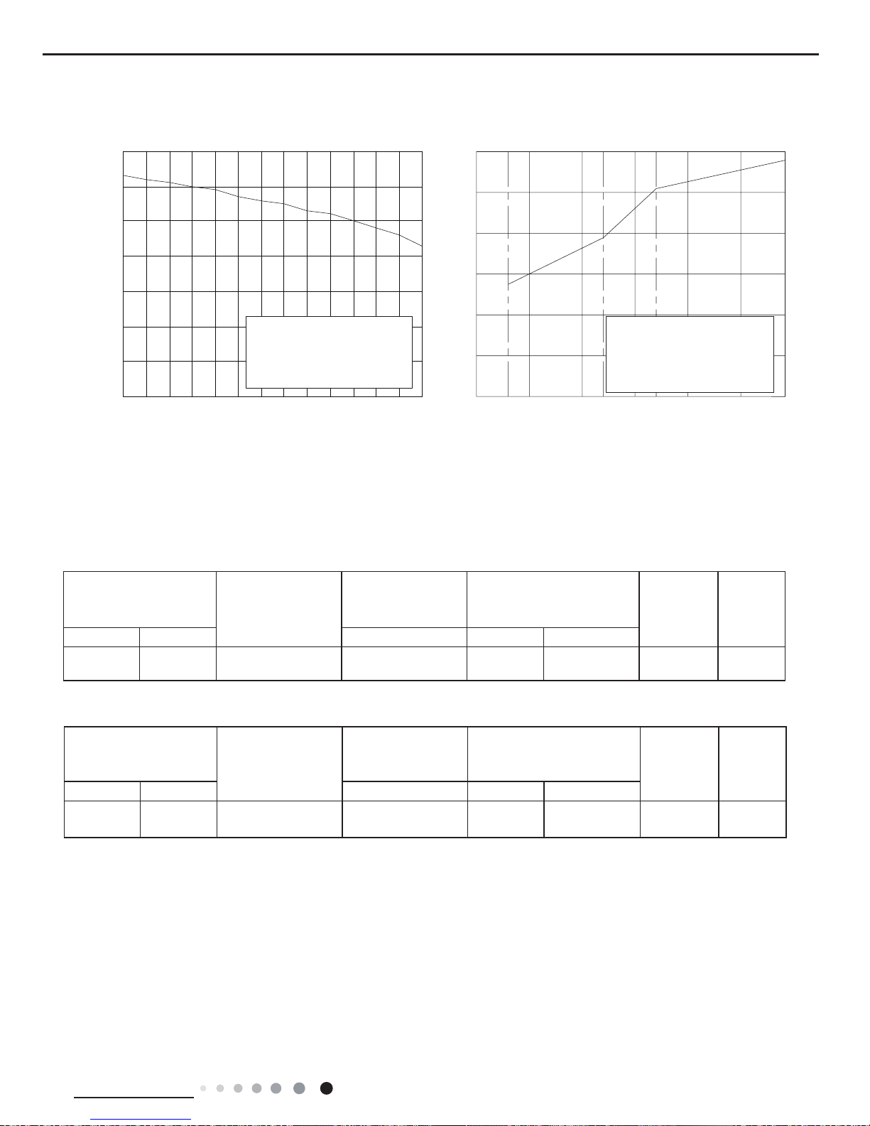
2.2 Capacity Curve in Different Outdoor Temperature
2.3 Cooling and Heating Data Sheet in Rated Frequency
Instruction:
T1: Inlet and outlet pipe temperature of evaporator
T2: Inlet and outlet pipe temperature of condenser
P: Pressure at the side of big valve
Connection pipe length: 5 m.
Cooling: Heating:
40
50
60
70
80
90
10 0
11 0
32 33 34 35 36 37 38 39 40 41 42 43
44 45
Outdoor temp.(°C)
C
apacity ratio
(%)
Conditio n
Indoor:DB27
°C
WB19
°C
Indoor air flow: Super High
Pipe length: 5m
Capacity ratio (
%)
157-7 -5 02
24
0
20
40
60
80
100
120
-10510
Outdoor Temp.(°C)
Condition Heating
Indoor:DB20
°C
Indoor air flow: Super High
Pipe length: 5m
Rated cooling condition(°C)
(DB/WB)
Model
Pressure of gas pipe
connecting indoor and
outdoor unit
Inlet and outlet pipe
temperature of heat exchanger
Fan speed of
indoor unit
Fan speed
of outdoor
unit
Indoor Outdoor P (MPa) T1 (°C) T2 (°C)
27/19 35/24 09K 0.9~1.1
in:10~14
out:11~14
in:72~83
out:35~40
Super High High
Rated heating condition(°C)
(DB/WB)
Model
Pressure of gas pipe
connecting indoor and
outdoor unit
Inlet and outlet pipe
temperature of heat exchanger
Fan speed of
indoor unit
Fan speed
of outdoor
unit
Indoor Outdoor P (MPa) T1 (°C) T2 (°C)
20/- 7/6 09K 2.3~2.5
in:61~65
out:30~37
in:1~2
out:2~4
Super High High
Cooling:
Heating:
10
Technical Information
Service Manual
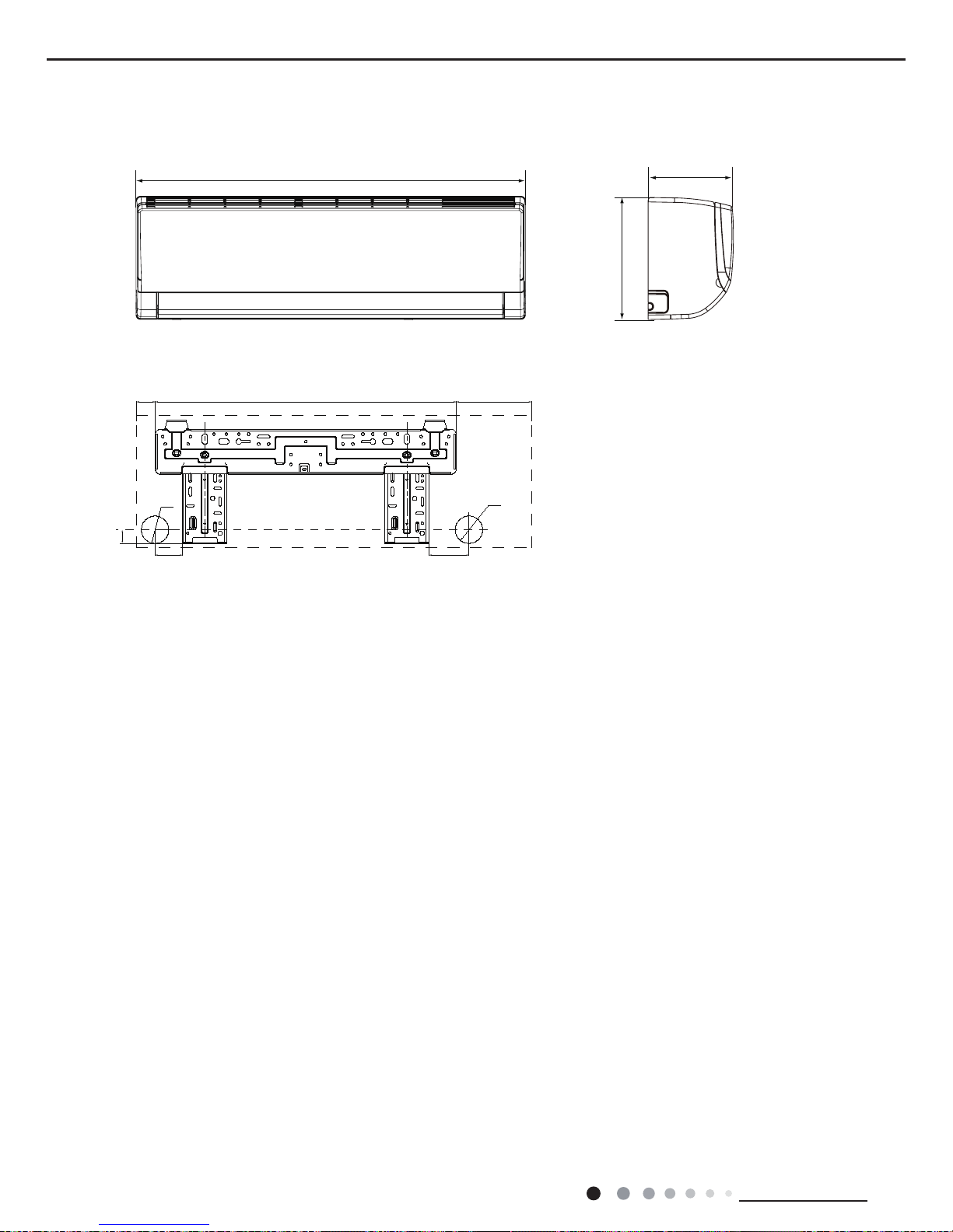
3. Outline Dimension Diagram
3.1 Indoor Unit
Unit:mm
790
174
605
148
265
37
Φ55
55
Φ55
28
80
11
Technical Information
Service Manual
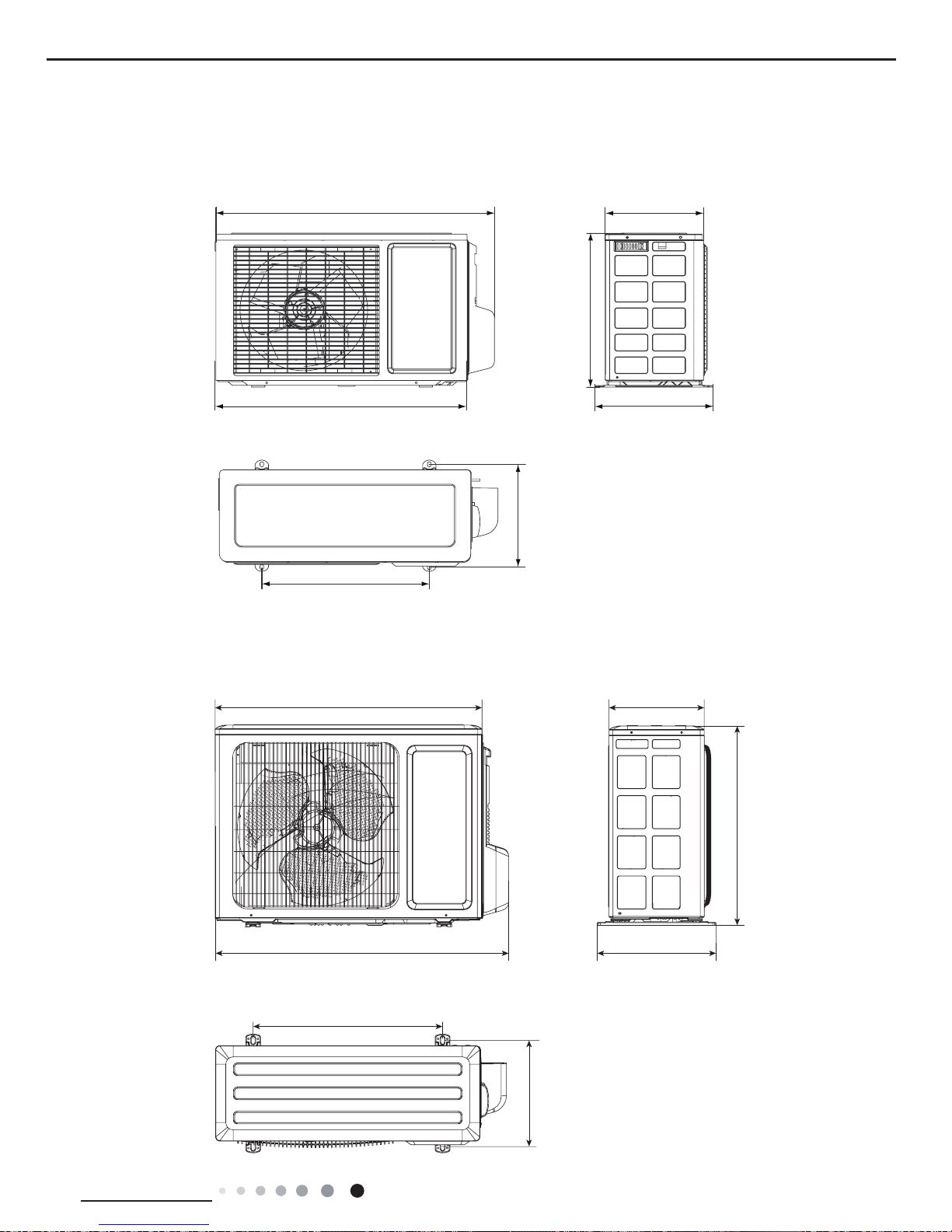
720
255
824
440
660
310
682
3.2 Outdoor Unit
Unit:mm
Unit:mm
712
776
510
320
257
286
540
GWC09MA-K3NNE1D/O GWC09MA-K3NNA5F/O
GWH09MA-K3NNA5F/O
12
Technical Information
Service Manual
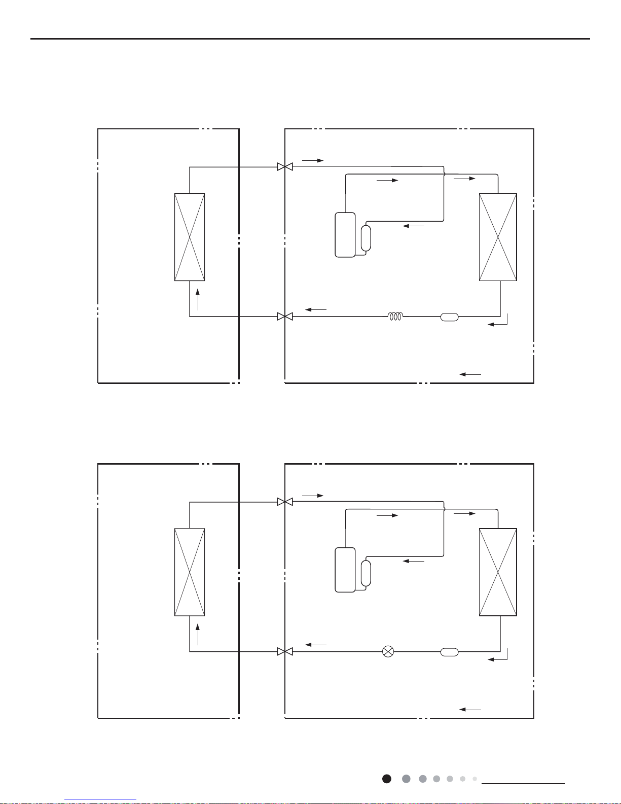
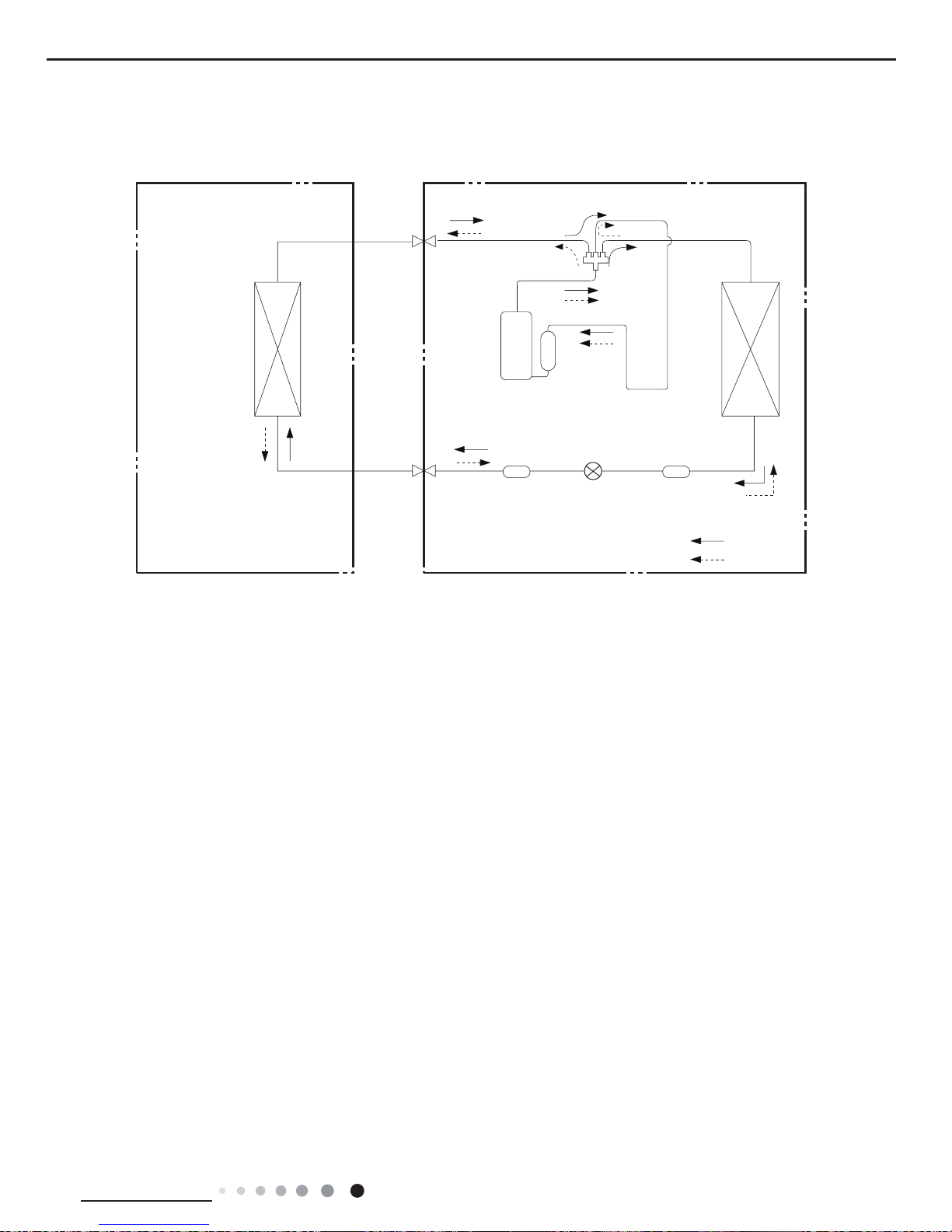
4. Refrigerant System Diagram
Indoor unit
Outdoor unit
Accumlator
COOLING
Discharge
Suction
Heat
exchanger
(evaporator)
Heat
exchanger
(condenser)
Valve
Valve
Liquid pipe
side
Gas pipe
side
Compressor
Strainer
Capillary
GWC09MA-K3NNA3D GWC09MA-K3NNC3D GWC09MA-K3NND3D
GWC09MA-K3NNA5F GWC09MA-K3NNA4F
Indoor unit
Outdoor unit
Accumlator
COOLING
Discharge
Suction
Heat
exchanger
(evaporator)
Valve
Valve
Liquid pipe
side
Gas pipe
side
Compressor
Strainer
Throttle Valve
13
Technical Information
Service Manual
Indoor unit
Outdoor unit
COOLING
HEATING
4-Way valve
Discharge
Suction
Heat
exchanger
(evaporator)
Heat
exchanger
(condenser)
Valve
Valve
Liquid pipe
side
Gas pipe
side
Strainer
Accumlator
Compressor
Strainer
Throttle Valve
GWH09MA-K3NNA5F GWH09MA-K3NNA4G
Connection pipe
specication:
Liquid pipe:1/4" (6mm)
Gas pipe:3/8" (9.52mm)
14
Technical Information
Service Manual
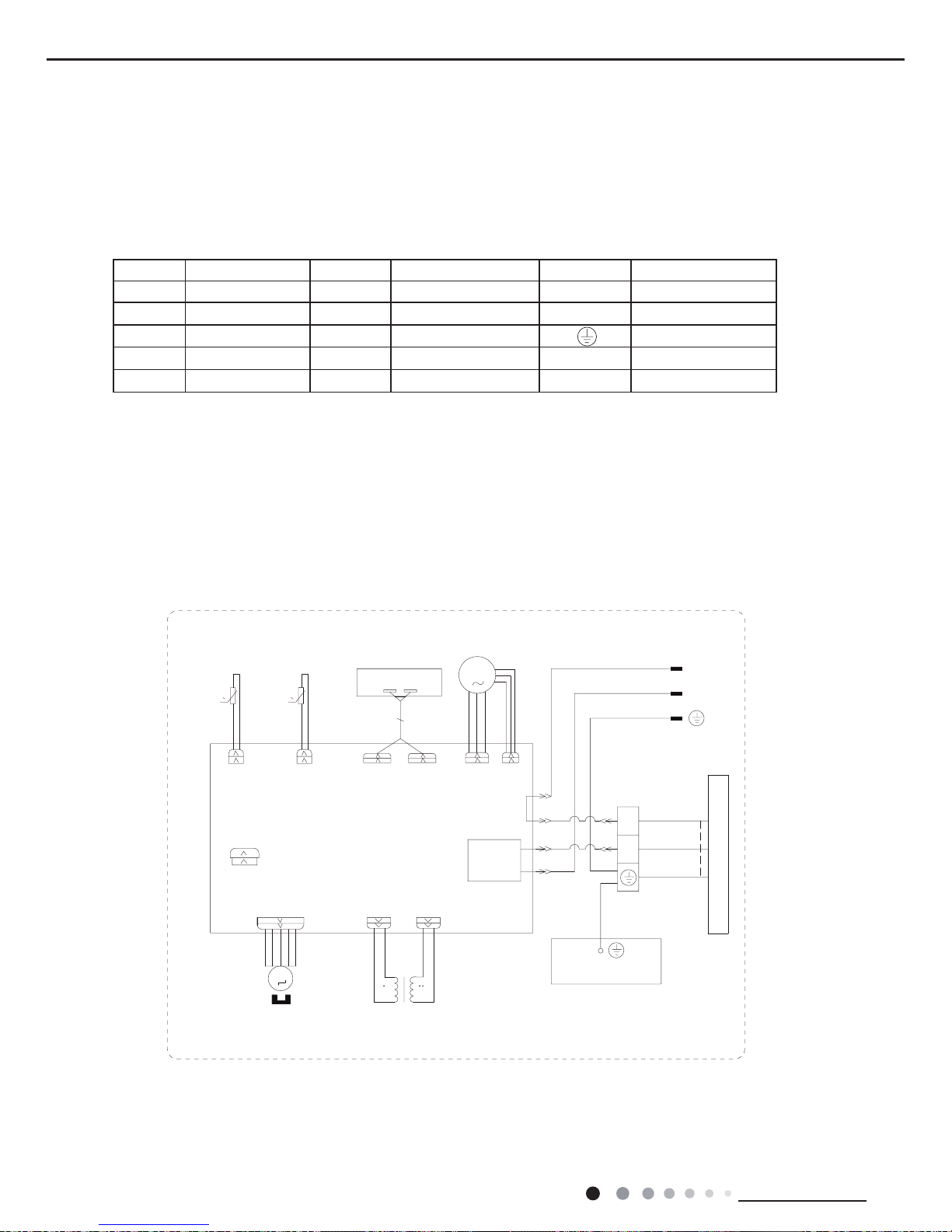
5. Electrical Part
5.1 Wiring Diagram
● Indoor Unit
●Instruction
Symbol Symbol Color Symbol Symbol Color Symbol Name
WH White GN Green CAP Jumper cap
YE Yellow BN Brown COMP Compressor
RD Red BU Blue Grounding wire
YEGN Yellow/Green BK Black / /
VT Violet OG Orange / /
Note: Jumper cap is used to determine fan speed and the swing angle of horizontal lover for this model.
GWC09MA-K3NNA3D/I GWC09MA-K3NNC3D/I GWC09MA-K3NND3D/I GWC09MA-K3NNA5F/I GWC09MA-K3NNA4F/I
GWC09MA-K3NNA9F/I GWC09MA-K3NNB3F/I GWC09MA-K3NNC9D/I
0
0
K1
AC-L
COMP
MOTOR
DISPLAY
RECEIVER AND
DISPLAY BOARD
DISP2
AP1
DISP1
STEPPING
N1
YEGN(GN)
BU
BK
BU(WH)
BN(BK)
POWER
TUBE TEMP.
ROOM TEMP.
SENSOR
SENSOR
TUBE
RT1
RT2
ROOM
AP2 PRINTED CIRCUIT BOARD
JUMP
CAP
OUTDOOR UNIT
SWING-UD
M2
N(1)
2
XT
BU
BK
YEGN
EVAPORATOR
PE
YEGN
PGF
PG
FAN MOTOR
M1
TERMINAL
BOARD
CONNECTING
CABLE
TC
TR_OUT
TR_IN
TRANSFORMER
N
L
III
15
Technical Information
Service Manual
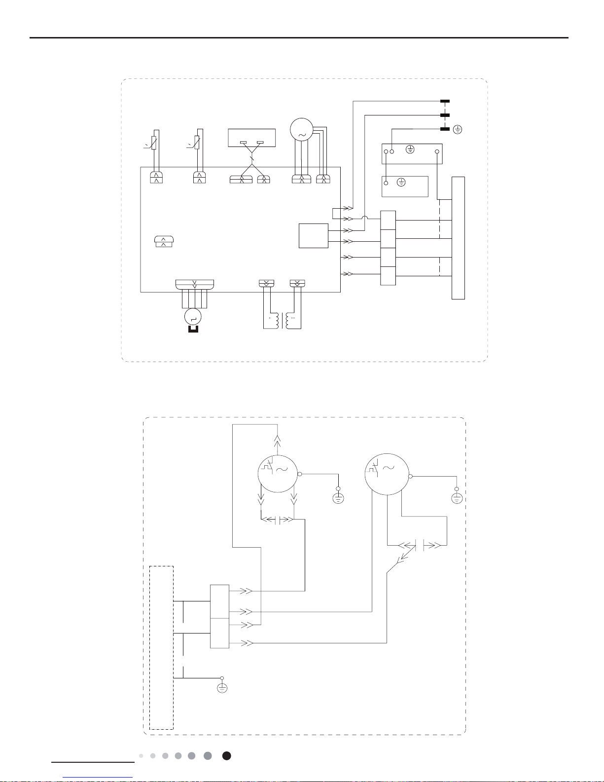
● Outdoor Unit
GWH09MA-K3NNA5F/I GWH09MA-K3NNA4G/I GWH09MA-K3NNA9F/I GWH09MA-K3NNB3F/I
GWC09MA-K3NNE1D/O GWC09MA-K3NNA5F/O
CABLE
C0NNECTING
BLOCK
TERMINAL
TR_IN
TR_OUT
TC
DISP1
AP1
DISP2
DISPLAY BOARD
RECEIVER AND
TRANSFORMER
STEPPING MOTOR
M1
FAN MOTOR
PG
PGF
TUBE TEMP.
ROOM TEMP.
SENSOR
SENSOR
TUBE
RT1
RT2
ROOM
AP1 PRINTED CIRCUIT BOARD
JUMP
CAP
OUTDOOR UNIT
SWING-UD
M2
N(1)
2
4
5
OG
VT
BK
BU
K1
AC-L
COMP
OG
VT
OFAN
4V
XT
BK
BU
N1
EARTH-PLATE
PE
PE
EVAPORATOR
YEGN
BU(WH)
BN(BK)
YEGN(GN)
YEGN
POWER
DISPLAY
0
0
III
N
L
MOTOR
M2
FAN
M1
N(1)
INDOOR UNIT
YEGN
BK
BU
BU
BK
BU
YE
BU
C1
BN
C2
RD
S(X)
BK
C(U)
E
R(M,V)
E
YEGN
COMP
E
E
YEGN
MOTOR
E
2
(BK)
(BN)
XT1
16
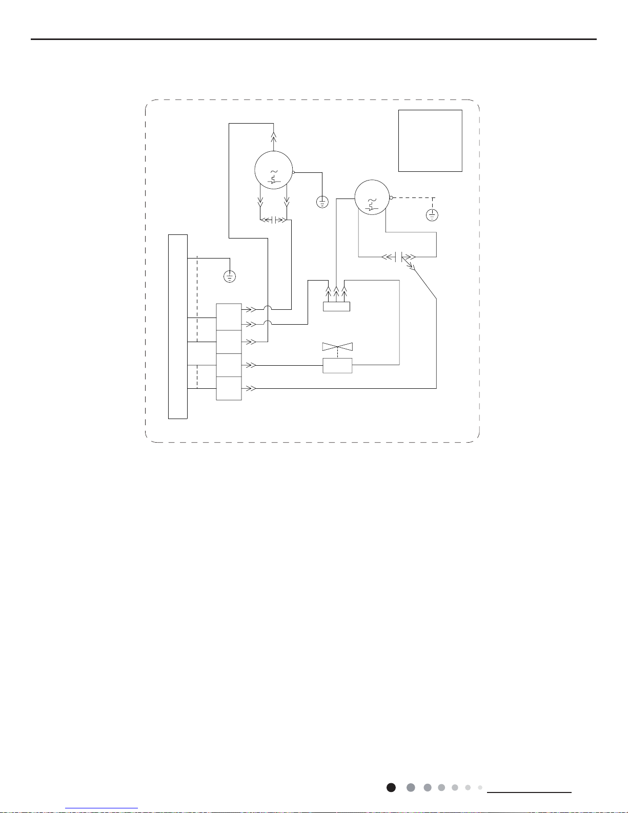
Technical Information
Service Manual
These wiring diagrams are subject to change without notice; please refer to the one supplied with the unit.
GWH09MA-K3NNA5F/O
&203
6
&
&
&$3
3(
50
3(
3(
3(
&
3(
<(*1
%8
<(
%.
<(*1
%8
%.
97
2*
%8
%8
,1'22581,7
2*
5'
%1
%8%.
<(*1
0
)$1
02725
&203
7(50,1$/
%/2&.
:$<
7(50,1$/
%/2&.
;7
;7
97
1
<9
9$/9(
97
VKHOOPRWRU
WRWKHLURQ
RQO\DSSOLHV
0RWRUJURXQG
127(
&$3
17
Technical Information
Service Manual
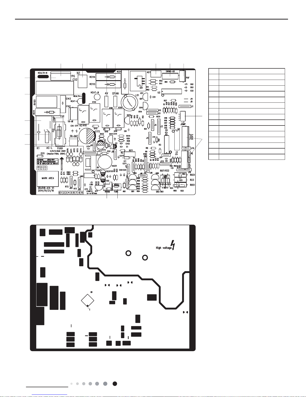
1
2
3
4
5
67 89
10 11 12
13
14
1516
1Fuse
2Live wire
3Compressor
4Live wire for healthy function
5Neutral wire for healthy function
6Control interface for PG motor
7Neutral wire
84-way valve
9Outdoor fan
10 Auto button
11 Up&down swing
12 Feedback interface for PG motor
13 Jumper cap
14 Display interface
15 Tube temperature sensor
16 Ambient temperaturesensor
5.2 PCB Printed Diagram
● Top view
● Bottom view
18
Technical Information
Service Manual
6. Function and Control
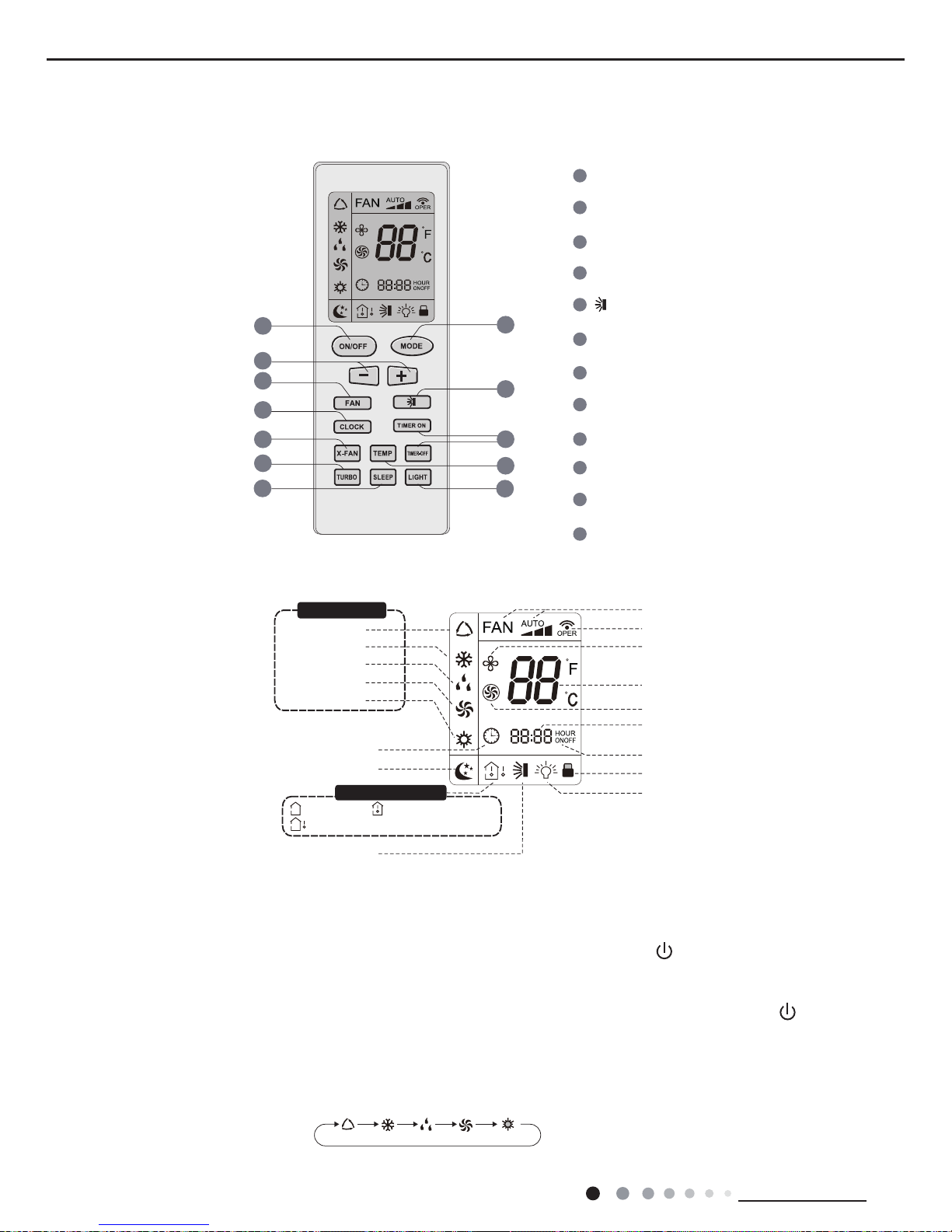
6.1 Remote Controller Introduction
Buttons on Remote Controller
Introduction
for Icons on Display Screen
Introduction for Buttons on Remote Controller
Auto mode
Cool mode
Heat mode
Fan mode
Dry mode
Clock
Light
Child lock
TIMER ON/TIMER OFF
Up&down swing
:Indoor ambient temp.
:Set temp.
:Outdoor ambient temp.
Sleep mode
Set temperature
Send signal
Turbo mode
Set time
X-fan mode
Set fan speed
ON/OFF Button
2
3
1
5
6
4
8
9
7
11
12
10
MODE Button
+/- Button
FAN Button
TIMER ON/TIMER-OFF Button
X-FAN Button
TEMP Button
LIGHT Button
SLEEP Button
CLOCK Button
TURBO Button
Button
2
6
8
3
9
10
7
5
12
11
4
1
Operation mode
Temp. display type
1. ON/OFF Button
Press this button canturnonorturnoff theair conditioner.After turning on the air conditioner, operation indicator " "on indoor
unit’s display is ON (green indicator. The colour is different for different models), and indoor unit will give out a sound.
2. MODE Button
Press this button to select your required operation mode.
Note:After putting through the power, the air conditioner will give out a sound. Operation indictor "
" is ON (red indicator).
After that,
you can operate the air conditioner by using remote controller.
AUTO COOL DRY FANHEAT
Operation mode
Temp. display type
19
Technical Information
Service Manual
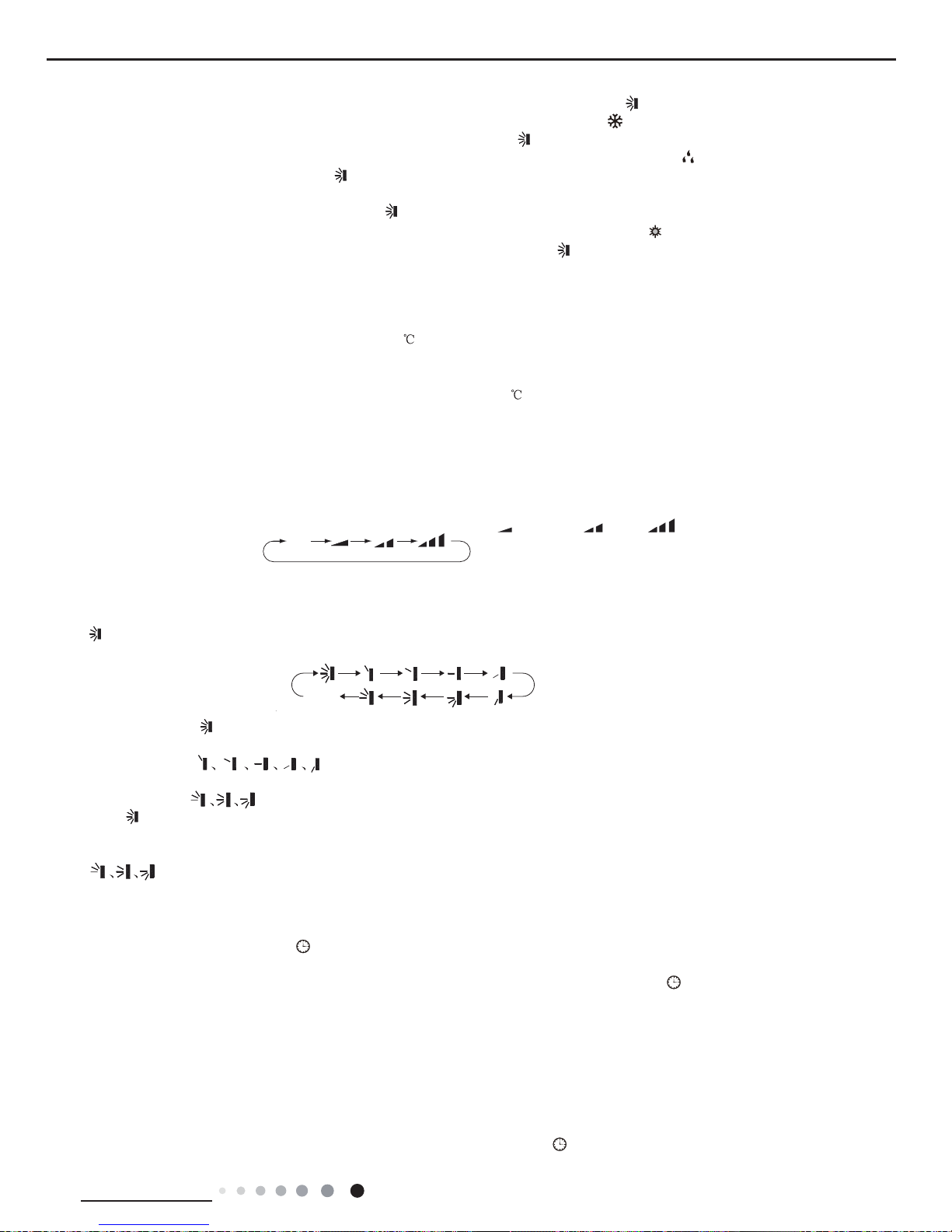
4. F
AN Button
Pressing this button can set fan speed circularly as: auto (AUT
O), low(
) ,medium( ),high( ).
Note:
● Under
AUTO speed, the IDU fan motor will adjust the fan speed (high, medium or low speed) according to ambient temperature.
● Fan speed under dry mode is low speed.
● When selecting auto mode, Air conditioner will start auto operation according to indoor ambient temperature.Settemperature can’t be
adjusted and will not be displayed as well. Press "F
AN" button can adjust fan speed. Press " " button can adjust fan blowing angle.
●
After selecting cool mode, air conditioner will operate under cool mode. Cool indicator " " on indoor unit is ON. Press "+" or "-" button
to adjust set temperature. Press "F
AN" button to adjust fan speed. Press " " button to adjust fan blowing angle.
● When selecting dry mode, the air conditioner operates at low speed under dry mode. Dry indicator "
" on indoor unit is ON. Under dry
mode, fan speed can’t be adjusted. Press "
" button to adjust fan blowing angle.
●
When selecting fan mode, the air conditioner will only blow fan, no cooling andnoheating.Allindicators areOFF.Operation indicatoris
ON.Press "F
AN" button to adjust fan speed. Press "
" button to adjust fan blowing angle.
●
When selecting heating mode, the air conditioner operates under heat mode. Heat indicator"
"onindoor unit is ON. Press “+” or “-“
button
to adjust set temperature Press “FAN” button to adjust fan speed. Press "
"buttontoadjust fanblowingangle.(Coolingonly unit
won’t receive heating mode signal. If setting heat mode with remote controlle
r, press ON/OFF button can’t start up the unit).
Note:
●
For preventing cold air, after starting up heating mode, indoor unit will delay1~5minutes to blow air(actual delaytimeisdepend on
indoor ambient temperature).
● Set temperature range from remote controller: 16~30
; Fan speed: auto, low speed,medium speed, high speed.
3. “+” or“-” Button
●
Press “+” or “-“ button once increase or decrease set temperature 1 .Holding "+" or "-"button, 2s later, settemperature on remot
e
controller
will change quickly. On releasing buttonaftersetting is finished, temperatureindicator on indoor unit will change accordingly
.
(T
emperature can’t be adjusted under auto mode)
●W
hensetting TIMER ON,TIMER OFFor CLOCK,press “+” or “-“ buttonto adjusttime.(Refer to CLOCK,TIMER ON, TIMER OF
F
buttons)
6. CLOCK Button
Press
this button to set clock time. " " icon on remote controller willblink. Pess "+" or "-"buttonwithin 5s to setclock time.Each
pressing
of "+" or "-" button, clock time will increase or decrease1minute. Hold "+" or "-"button, 2s later, time will change quickly.
Release this button when reaching your required time. Press “CLOCK" button to confirm the time. "
" icon stops blinking.
Note:
● Clock time adopts 24-hour mode.
●T
he interval between two operation can’texceeds 5s. Otherwise, remote controller will quit setting status.Operation forTIMER
ON/TIMER OFF is the same.
7. TIMER-ON/TIMER-OFF Button
●
TIMER ON button
TIMER ON butto
n
“TIMER ON”buttoncan setthe time fortimer on.After pressing this button, "
"icondisappears andthe word “ON" on remote
5.
Button
Pressing this button can select up&down swing angle. Fan blow angle can be selected circularly as below
:
●W
hen selecting" ",air conditioner is blowing fan automatically.Horizontallouverwillautomatically swingup&down at
maximum angle.
●W
henselecting "
", airconditioner is blowingfan at fixedposition. Horizontal louver will stop at thefixed
position.
● When selecting "
”, air conditioner is blowing fan at fi xed angle. Horizontal louver will send air at the fixed angle.
● Hold "
" button above 2s to set your required swing angle. When reaching your required angle, release the button.
Note:
"
" may not be available. When air conditioner receives this signal, the air conditioner will blow fan automatically.
Auto
(horizontal louvers
stops at current position)
no display
20
Technical Information
Service Manual
controller blinks. Press "+" or "-"button to adjust TIMER ON setting. After each pressing "+" or "-"button, TIMER ON setting will increase
or decrease 1min. Hold "+" or "-"button, 2s late
r, the time will change quickly
until reaching your required time. Press “
TIMER ON”to confi rm it. The word “ON" will stop blinking. " " icon resumes displaying.
Cancel
TIMER ON: Under the condition that TIMER ON is started up, press “TIMER ON” button to cancel it.
●
TIMER OFF button
"TIMER
OFF" button can set the time for timer off. After pressing this button, " " icon disappears and the word "OFF" on remote
controller
blinks. Press "+" or "-" button to adjust TIMER OFF setting. After each pressing "+" or "-" button, TIMER OFF setting will
increase or decrease 1min. Hold "+" or "-" button, 2s late
r, the time will change
quickly
until reaching your required time. Press "TIMER OFF" to confirm it .The word "OFF"will stop blinking "
" icon resume
s
displaying. Cancel
TIMER OFF. Under the condition that TIMER OFF is started up, press “TIMER OFF” button to cancel it.
Note:
● Under on and of
f status, you can set TIMER OFF or TIMER on simultaneously.
● Before setting
TIMER ON or TIMER OFF, please adjust the clock time.
● After
starting up TIMER ON or TIMER OFF, set the constant circulating valid. After that, air conditioner will be turned on or turned of
f
according
to setting time. ON/OFF button has no effect on setting. If you don’t need this function, please use remote controller to cancel
it.
8. X-F
AN Button
Press
this button under cool and dry mode to start up x-fan function, and "
" icon on remote controller will be displayed. Press this
button again to cancel x-fan function, and "
"icon will disappear.
Note:
●
When x-fan function is on, if the air conditioner is turned off, indoor fan will still operate at low speed for a while to blow the residual
water inside the air duct
.
● During x-fan operation, press X-F
AN button to turn off x-fan function. Indoor fan will stop operation immediately.
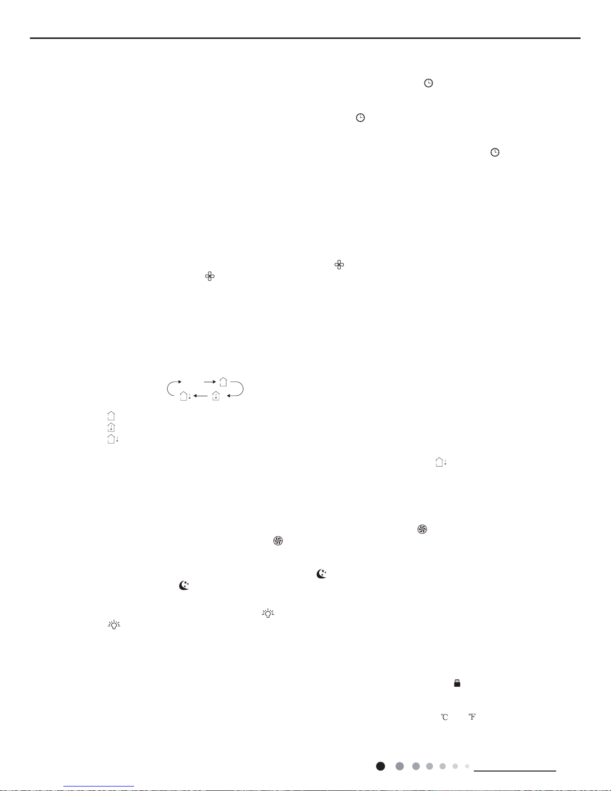
9. TEMP Button
By pressing this button, you can see indoor set temperature, indoor ambient temperature or outdoor ambient temperature on indoor
unit’s display. The setting on remote controlleris selected circularly as below:
When selecting "
" or no display with remote controller, temperature indicator on indoor unit displays set temperature;
When selecting " " with remote controller, temperature indicator on indoor unit displays indoor ambient temperature;
When selecting "
" with remote controller, temperature indicator on indoor unit displays outdoor ambient temperature.
Note:
● Outdoor temperature display is not available for some models. At that time, indoor unit receives"
" signal, while it displays
indoor set temperature.
● It’s defaulted to display set temperature when turning on the unit.There is no display in the remote controller.
● Only for the models whose indoor unit has dual-8 display
10. TURBO Button
Under COOL or HEAT mode, press this button to turn to quick COOL or quick HEAT mode. "
" icon is displayed on remote
controller. Press this button again to exit turbo function and " " icon will disappear.
11. SLEEP Button
Under COOL, HEAT mode, press this button to start up sleep function. "
" icon is displayed on remote controller. Press this button
again to cancel sleep function and "
" icon will disappear.
12. LIGHT Button
Press this button to turn off display light on indoor unit. "
" icon on remote controller disappears. Press this button again to turn
on display light. "
" icon is displayed.
Child lock function:
Press "+"and "-" simultaneously to turn on or turn off child lock function. When child lock function is on, " " icon is displayed on
remote controller. If you operate the remote controller, it won’t send signal.
Temperature display switchover function:
Under OFF status, press "-" and "MODE" buttons simultaneously to switch temperature display between and .
no display
Function Introduction for Combination Buttons
 Loading...