

Gree GWH(18)MC-K3DNA3B, GWH(12)MB-K3DNA2B, GWH(18)MC-K3DNA2B, GWH(12)MB-K3DNA3B, GWH(09)MA-K3DNB8B Service Manual
...
MODELS: GWH(09)MA-K3DNA2B/I
GWH(12)MB-K3DNA2B/I
GWH(18)MC-K3DNA2B/I
GWH(07)MA-K3DNA3B/I
GWH(09)MA-K3DNA3B/I
GWH(12)MB-K3DNA3B/I
GWH(18)MC-K3DNA3B/I
GWH(09)MA-K3DNB8B/I
GWH(12)MB-K3DNB8B/I
GWH(07)MA-K3DNC5B/I
GWH(09)MA-K3DNC5B/I
GWH(12)MB-K3DNC5B/I
GWH(18)MC-K3DNC5B/I
GWH(07)MA-K3DNB8B/I(Cold plasma)
GWH(09)MA-K3DNB8B/I(Cold plasma)
GWH(12)MB-K3DNB8B/I(Cold plasma)
GWH(18)MC-K3DNB8B/I(Cold plasma)
GREE ELECTRIC APPLIANCES,INC.OF ZHUHAI
Service Manual
Change for Life

Table Contents
Summary and Features
....................................................................................1
Part 1 Safety Precautions
...........................................................................................2
Part 2 Specifications
..................................................................................................... 3
2.1 Unit Specifications ..................................................................................................3
2.2 Capacity Variation Ratio According to Temperature...............................................4
Part 3 Construction Views
.........................................................................................5
Part 4 Refrigerant System Diagram
......................................................................6
5.1 Electrical Data.........................................................................................................7
5.2 Electrical Wiring.......................................................................................................7
Part 5 Schematic Diagram
.........................................................................................7
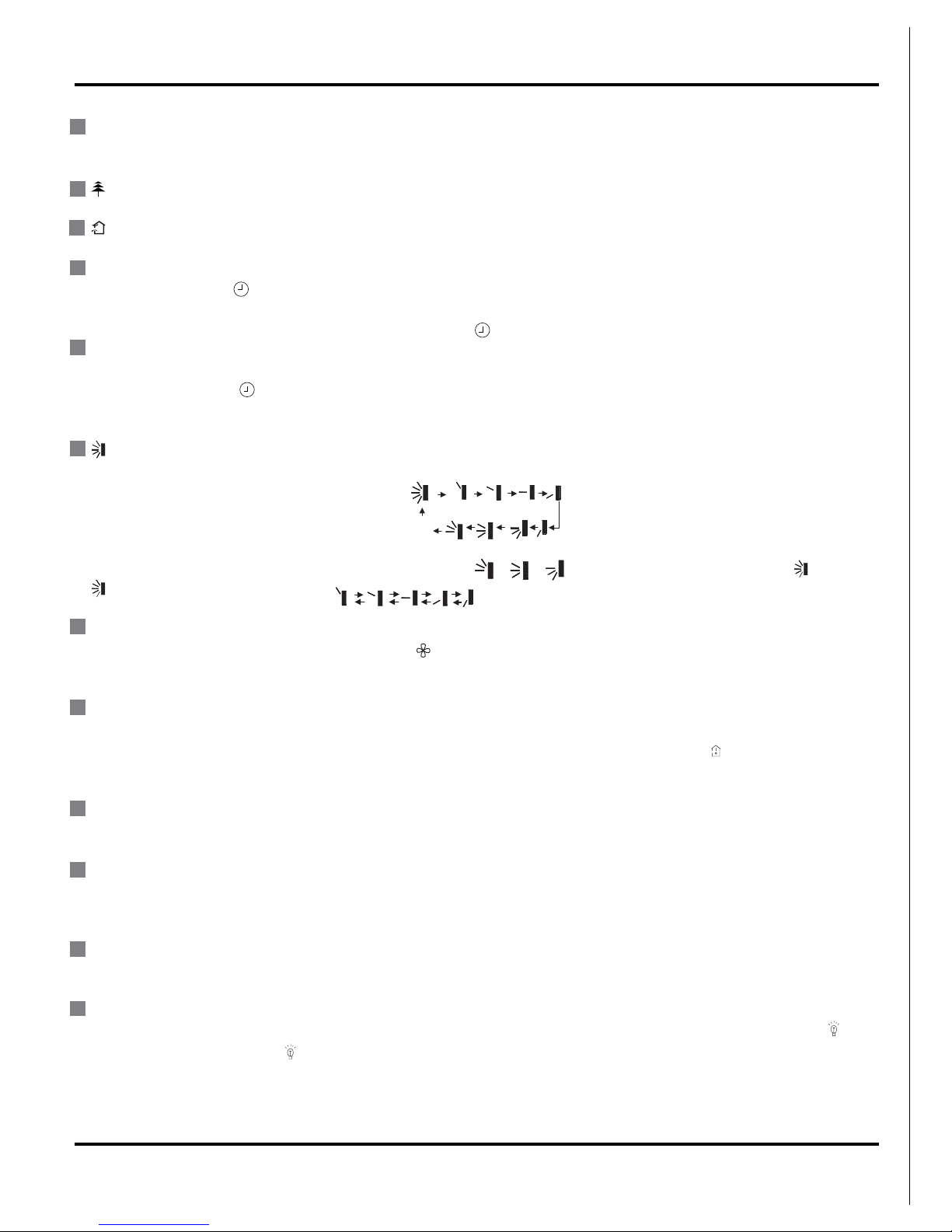
6.1 Remote Control Operations 11
6.2 Description of Each Control Operation..................................................................
15
Part 6 Function and Control
....................................................................................11
Part 7 Installation Manual
..........................................................................................
18
5.3 Printed Circuit Board...............................................................................................9
7.1 Notices for Installation............................................................................................18
7.3 Install Indoor Unit..................................................................................................20
7.4 Check After Installation and Test Operation
.......................................................22
..........................................................21
7.2 Installation Drawing
........................................................................................19
Part 8 Exploded Views and Parts List
...............................................................
23
Part 9 Troubleshooting
................................................................................................
39
9.1
.....................................................................................................
39
9.2
.........................................................................
42
Part10 Removal Procedure
.........................................................................................
48
...................................................................................
7.5 Installation and Maintenance of Healthy Filter
Malfunction Display
How to Check Simply the Main Part
1
Summary and features
Indoor Unit
Remote Controller
YT1F
Summary and features
GWH(07)MA-K3DNA3B/I
GWH(09)MA-K3DNA3B/I
GWH(12)MB-K3DNA3B/I
GWH(18)MC-K3DNA3B/I
FAN
MODE
IFEEL
CLOCK
TIMER
ON
X-FAN TEMP
TIMER
OFF
TURBO SLEEP LIGHT
GWH(09)MA-K3DNA2B/I
GWH(12)MB-K3DNA2B/I
GWH(18)MC-K3DNA2B/I
GWH(09)MA-K3DNB8B/I
GWH(12)MB-K3DNB8B/I
GWH(07)MA-K3DNB8B/I(Cold plasma)
GWH(09)MA-K3DNB8B/I(Cold plasma)
GWH(12)MB-K3DNB8B/I(Cold plasma)
GWH(18)MC-K3DNB8B/I(Cold plasma)
GWH(07)MA-K3DNC5B/I
GWH(09)MA-K3DNC5B/I
GWH(12)MB-K3DNC5B/I
GWH(18)MC-K3DNC5B/I
2
Safety Precautions
1.Safety Precautions
Installing, starting up, and servicing air conditioner can be
hazardous due to system pressure, electrical components,
and equipment location, etc.
Only trained, qualified installers and service personnel are
allowed to install, start-up, and service this equipment.
Untrained personnel can perform basic maintenance functions such as cleaning coils. All other operations should
be performed by trained service personnel.
When handling the equipment, observe precautions in the
manual and on tags, stickers, and labels attached to the
equipment. Follow all safety codes. Wear safety glasses
andwork gloves. Keep quenching cloth and fire extinguisher
nearby when brazing.
Read the instructions thoroughly and follow all warnings or
cautions in literature and attached to the unit. Consult local
building codes and current editions of national as well as
local electrical codes.
Recognize the following safety information:
Incorrect handling could result in
personal injury or death.
Incorrect handling may result in
minor injury,or damage to product
or property.
Warning
Caution
Caution
Warning
All electric work must be performed by a licensed technician
according to local regulations and the instructions given in
this manual.
Before installing, modifying, or servicing system, main
electrical disconnect switch must be in the OFF position.
There may be more than 1 disconnect switch. Lock out
and tag switch with a suitable warning label.
Never supply power to the unit unless all wiring and tubing are completed, reconnected and checked.
This system adopts highly dangerous electrical voltage.
Incorrect connection or inadequate grounding can cause
personal injury or death. Stick to the wiring diagram and
all the instructions when wiring.
Have the unit adequately grounded in accordance with
local electrical codes.
All installation or repair work shall be performed by your dealer or a specialized subcontractor as there is the risk of fire,
electric shock, explosion or injury.
Have all wiring connected tightly. Loose connection may
lead to overheating and a possible fire hazard.
Make sure the outdoor unit is installed on a stable, level
surface with no accumulation of snow, leaves, or trash
beside.
Make sure the ceiling/wall is strong enough to bear the
weight of the unit.
Make sure the noise of the outdoor unit does not disturb
neighbors.
Follow all the installation instructions to minimize the risk
of damage from earthquakes, typhoons or strong winds.
Avoid contact between refrigerant and fire as it generates
poisonous gas.
Apply specified refrigerant only. Never have it mixed with
any other refrigerant. Never have air remain in the
refrigerant line as it may lead to rupture and other hazards.
Make sure no refrigerant gas is leaking out when installation is completed.
Should there be refrigerant leakage, the density of refrigerant in the air shall in no way exceed its limited value,
or it may lead to explosion.
Keep your fingers and clothing away from any moving
parts.
Clear the site after installation. Make sure no foreign objects are left in the unit.
Always ensure effective grounding for the unit.
Never install the unit in a place where a combustible gas
might leak, or it may lead to fire or explosion.
Properly insulate any tubing running inside the room to
prevent the water from damaging the wall.
Make a proper provision against noise when the unit is
installed at a telecommunication center or hospital.
Provide an electric leak breaker when it is installed in a
watery place.
Never wash the unit with water.
Should any emergency occur, stop the unit and disconnect the power immediately.
Handle unit transportation with care. The unit should not
be carried by only one person if it is more than 20kg.
Never touch the heat exchanger fins with bare hands.
Never touch the compressor or refrigerant piping without
wearing glove.
Do not have the unit operate without air filter.
3
2.Specifications
2.1 Unit Specifications
Specifications
The above data is subject to change without notice. Please refer to the nameplate of the unit.
Model
GWH(07)MA-K3DNA3B/I
GWH(07)MA-K3DNC5B/I
GWH(07)MA-
K3DNB8B/I(Cold plasma)
GWH(09)MA-K3DNA2B/I
GWH(09)MA-K3DNA3B/I
GWH(09)MA-K3DNB8B/I
GWH(09)MA-K3DNC5B/I
GWH(09)MA-
K3DNB8B/I(Cold plasma)
GWH(12)MB-K3DNA2B/I
GWH(12)MB-K3DNA3B/I
GWH(12)MB-K3DNB8B/I
GWH(12)MB-K3DNC5B/I
GWH(12)MB-
K3DNB8B/I(Cold plasma)
GWH(18)MC-K3DNA2B/I
GWH(18)MC-K3DNA3B/I
GWH(18)MC-K3DNC5B/I
GWH(18)MC-
K3DNB8B/I(Cold plasma)
Product Code
CB171N0400
CB179N00900
CB174N02100
CB181N02700
CB171N0340
CB174N01900
CB179N01000
CB174N01901
CB181N02800
CB171N0350
CB174N02000
CB179N01100
CB174N02001
CB181N02900
CB171N0360
CB179N01200
CB174N02200
0035005300620012)W()gnilooC(yticapaC
0085008300820062)W()gnitae
H(yticapaC
Fan Motor Speed (r/min)
(SH/H/M/L)
1200/1050/920/730 1260/1050/920/730 (1260)/1070/900/730 1350/1200/1050/900
058036005054)h/³m(wolfriA
02020101)W(rotoMnaFfotuptuO
Input Power of Heater
(W)
////
Fan Motor Capacitor (ȝ 5.1111)F
84.073.032.032.0)A(A
LRrotoMnaF
nafwolfssorCnafwolfssorCnafwolfssorCnafwolfssorCepyTnaF
Diameter-Length (mm) ĭ85X596 ĭ85X596 ĭ92X645 ĭ98X710
Evaporator Aluminum fin-copper tube Aluminum fin-copper tube Aluminum fin-copper tube Aluminum fin-copper tube
Pipe Diameter (mm) ĭ7 ĭ7 ĭ7 ĭ7
4.1-24.1-25.1-25.
1-2)mm(paGniF-woR
Coil length (l)Xheight
(H)X coil width (L)
581X264X25.4 581X264X25.4 645X267X25.4 715X304.8X25.4
Swing Motor Model MP24AA MP24AA MP24AA MP28VB
Output of Swing Motor
(W)
25.15.15.1
A51.3BCPA51.3BCPA51.3BCPA51.3BCP)A(esuF
Sound Pressure Level dB
(A) (SH/H/M/L/SL)
36/34/31/28/- 37/34/31/28/- 38/34/32/30/- 46/43/40/36/-
Sound Power Level dB
(A) (SH/H/M/L/SL)
46/44/41/38/- 47/44/41/38/- 48/44/42/40/- 56/53/40/36/-
Dimension (WXHXD) (
mm)
790X265X170 790X265X170 845X275X180 940X298X200
Dimension of Package
()(mm)
Liquid connections
Diameter
ĭ6(1/4ͳ) ĭ6(1/4ͳ) ĭ6(1/4ͳ) ĭ6(1/4
ͳ
)
Gas connections
Diameter
ĭ9.52(3/8ͳ) ĭ9.52(3/8ͳ)
ĭ9.52(3/8”)
ĭ12(1/2ͳ)
Net Weight /Gross
Weight (kg)
71/3131/0121/921/9
Dimension of Carton
Box (LXWXH)
870X248X355 915X255X355870X248X355 1010X285X380
LXWXH
873X251X370 918X258X370873X251X370 1013X288X395
4
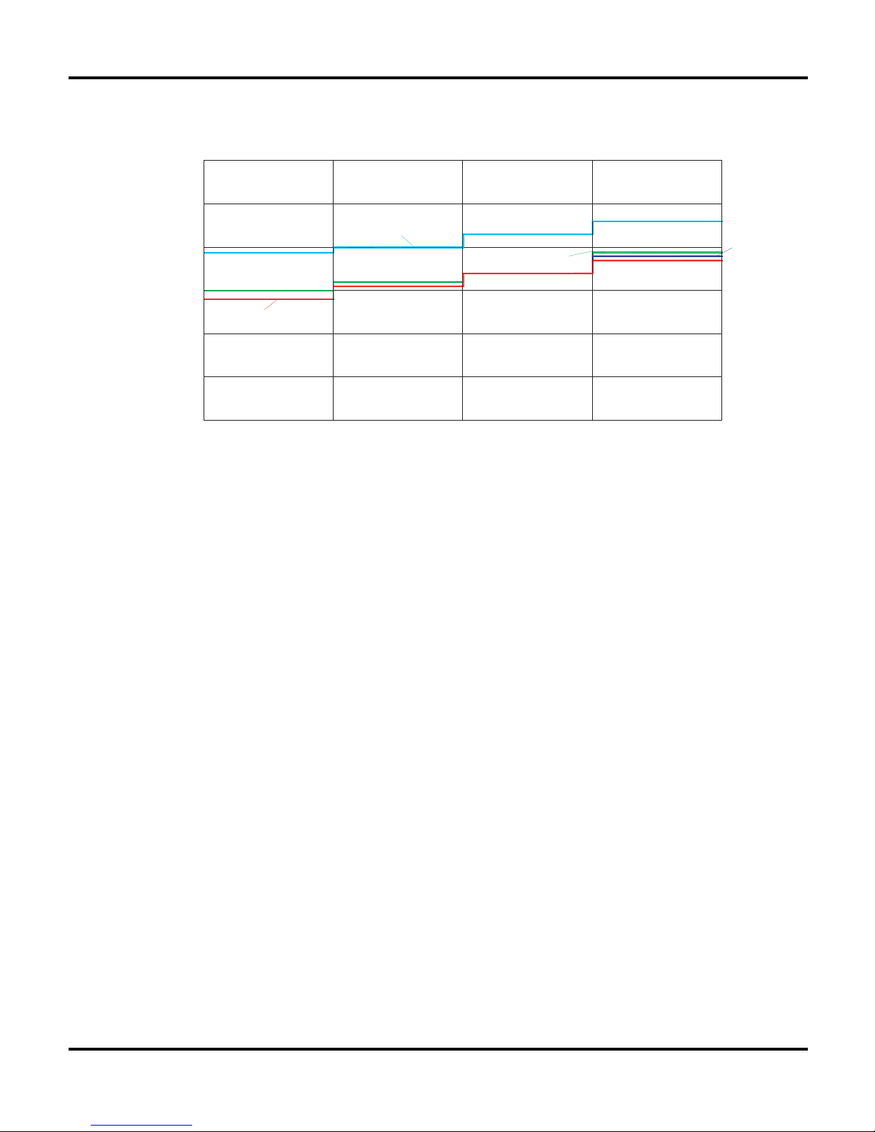
2.2 Noise Criteria Curve Tables for Both Models
Specifications
.
.
.
.
0
10
Noice/dB(A)
20
30
40
50
60
Low
Middle
High Super High
Indoor Fan Motor Rotating Speed
5
Q
SR
W
H
D
ĭ;
Q
SR
ĭ;
Q
SR
ĭ;
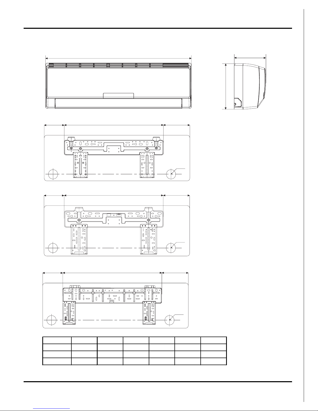
3. Construction Views
Constrction views
7K&09K
.
18K
Model(mm) W H D Q R S
7K&09K 790 6 170 3 60 10
1K847 180 134 40 171
18K 940 98 00 108 694 138
6
4. Refrigerant System Diagram
Cooling & Heating Models
Refrigerant System Diagram
outdoor
indoor
D1
C
1
B1
A1
filter
A heat exchanger
gas -liquid separator
inverter compressor
discharge silencer
discharge temperature
sensor
SP
4-way valve
outdoor heat exchanger
fan
high pressure switch
B heat exchanger
C heat exchanger
D heat exchanger
filter
filter
filter
filter
Note: Not available for 14K/18K
model
C2
C3
D3
D2
B3
B2
A2
A3
A1:A-unit electronic expansion valve B1:B-unit electronic expansion valve
C1:C-unit electronic expansion valve D1:D-unit electronic expansion valve
A2:A-unit gas pipe temperature sensor B2:B-unit gas pipe temperature sensor
C2:C-unit gas pipe temperature sensor D2:D-unit gas pipe temperature sensor
A3:A-unit liquid pipe temperature sensor B3:B-unit liquid pipe temperature sensor
C3:C-unit liquid pipe temperature sensor D3:D-unit liquid pipe temperature sensor
Note: Not available for 14K/18K model

7
5. Schematic Diagram
5.1 Electrical Data
5.2 Electrical Wiring
Schematic Diagram
Symbol Color symbol Symbol Color symbol
WH WHITE BN BROWN
YE YELLOW BU BLUE
RD
RED
BK
BLACK
YEGN YELLOW GREEN VT VIOLET
OG ORANGE PROTECTIVE EARTH
SAT OVERLOAD COMP COMPRESSOR
Meaning of marks
AC-L
3BK
TEM.SENSOR
TEM.SENSOR
PE
BK
ROOM
TUBE
M2
SWING-UD
ROOM
RT2
AP2
2BN
PG
4YEGN
0
M1
1BU
FAN
Outdoor Unit
BN
2
YEGN
3
BU
XT
N(1)
TUBE
0
RT1
SWING
MOTOR
COM-OUT
N
PGF
MOTOR
CAP
JUMP
DISP2DISP1
AP1
RECEIVER AND
DISPLAY BOARD
BU
RD
HEALTH-N
HEALTH-L
GENERATOR
COOL PLASMA
NOTE:The parts with broken line is applicable
to the models with COOL PLASMA GENERATOR
EVAPORATOR
For 07/09/12K Unit
8
Schematic Diagram
For 18K Unit
JUMP
CAP
EVAPORATOR
PE
TUBE
ROOM
N
DISP2
DISP1
AC-L
3BK
TEM.SENSOR
TEM.SENSOR
BK
AP1
ROOM
RT1
0
AP2
2BN
4YEGN
1BU
Outdoor Unit
BN
2
YEGN
3
BU
XT
N(1)
TUBE
0
RT2
COM-OUT
SWING-UD
PGFPG
FAN MOTOR
RECEIVER AND
DISPLAY BOARD
HEALTH-NHEALTH-L
COOL PLASMA
GENERATOR
BURD
SWING
MOTOR
M2
M1
(optional)
These circuit diagrams are subject to change without notice, please refer to the one supplied with the unit.
9
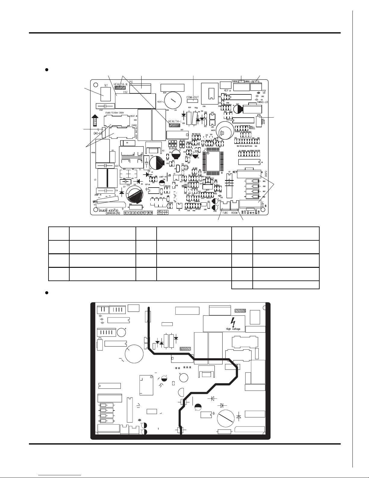
5.3 Printed Circuit Board
Schematic Diagram
BOTTOM VIEW
For 07/09/12K Unit
TOP VIEW
1
2
354678
9
10
1112
13
1
Power supply live wire
connector
5 Indoor fan wire terminal 9 Jumper cap terminal
2
Power supply neutral wire
connector
6
indoor and outdoor unit
communication wire terminal
10 Display panel terminal
3 Fan capacitor 7
Up & down swing control
terminal
11
Indoor ambient temperature
sensor
4
Health function
terminal(optional)
8 Indoor fan feedback terminal 12
Indoor pipe temperature
sensor
13 Protective tube
10
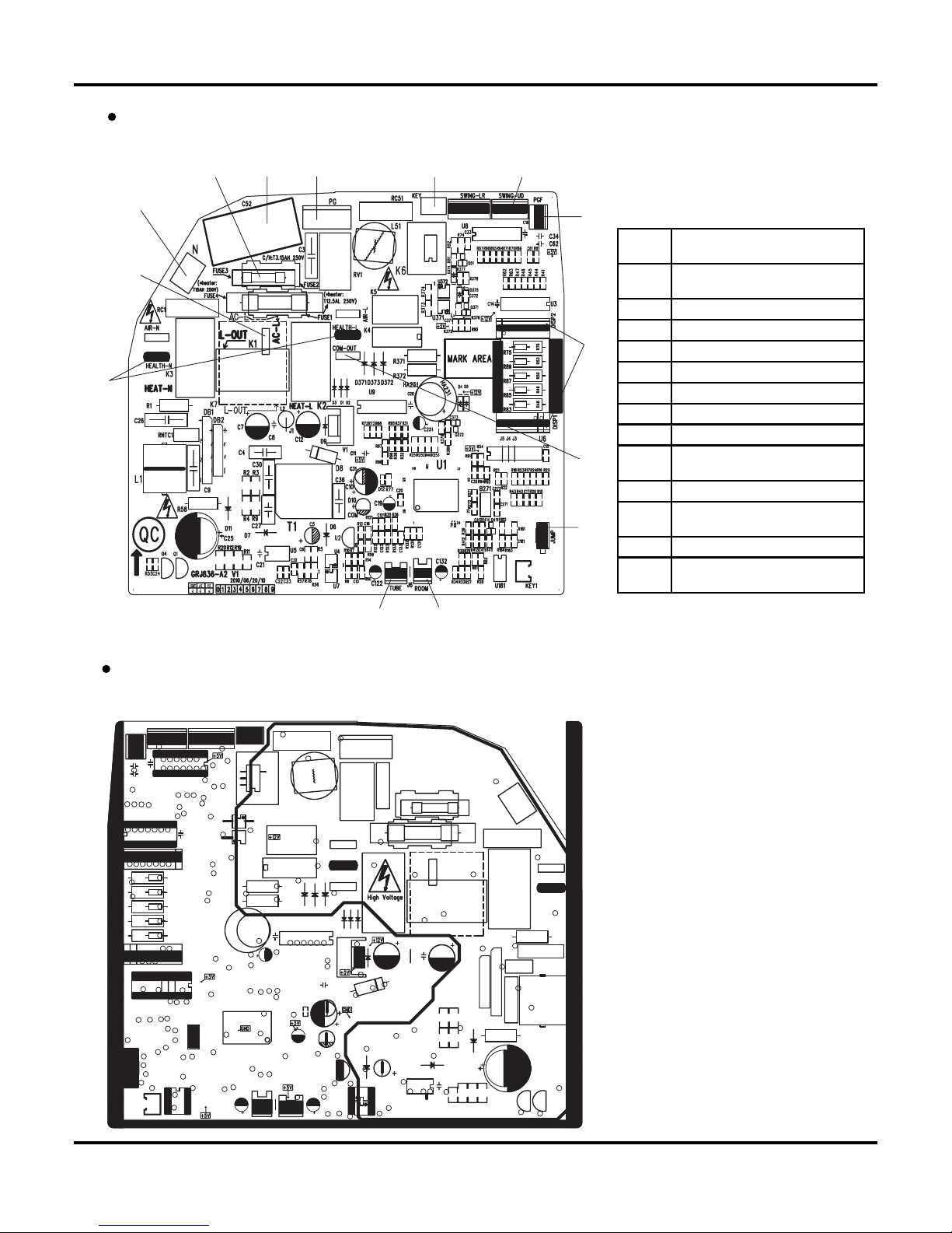
Schematic Diagram
BOTTOM VIEW
TOP VIEW
For 18K Unit
1
2
345 6 7
8
9
10
11
1213
14
1
Power supply live wire
connector
2
Power supply neutral wire
connector
3 Protective tube
4 Fan capacitor
5 PG motor connector
6 Auto button
7 Up & down swing connector
8 PG motor fan feedback terminal
9 Display panel connector
10
Indoor and outdoor unit
communication wire terminal
11 Jumper cap terminal
12
Indoor ambient temperature
sensor
13 Indoor pipe temperature sensor
14
Health function
terminal(optional)
11
Function and Control
6. Function and Control
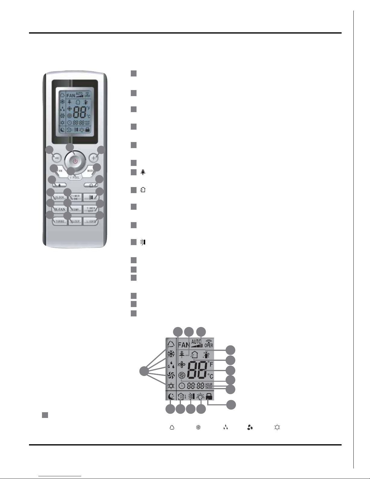
6.1 Remote Control Operations
ON/OFF
Press it to start or stop operation.
- :
Press it to decrease temperature setting.
+:
Press it to increase temperature setting.
FAN
Press it to set fan speed.
MODE
Press it to select operation mode (AUTO/COOL/DRY/FAN/HEAT).
I FEEL
Press it to set HE ALTH function
Press it to set AIR function.
CLOCK
Press it set clock.
TIMER ON
Press it to set auto-on timer.
Press it set swing angle.
X-FAN
TEMP
TIMER OFF
Press it to set auto-off timer
TURBO
SLEEP
LIGHT
Press it to turn on/off the light.
1
6
7
5
3
2
4
11
10
14
9
12
13
15
16
17
3
14
9
10
13
16
12
5
4
15
11
8
17
7
2
1
6
8
18
23
24
293031
19 20 21 22
26
28
27
25
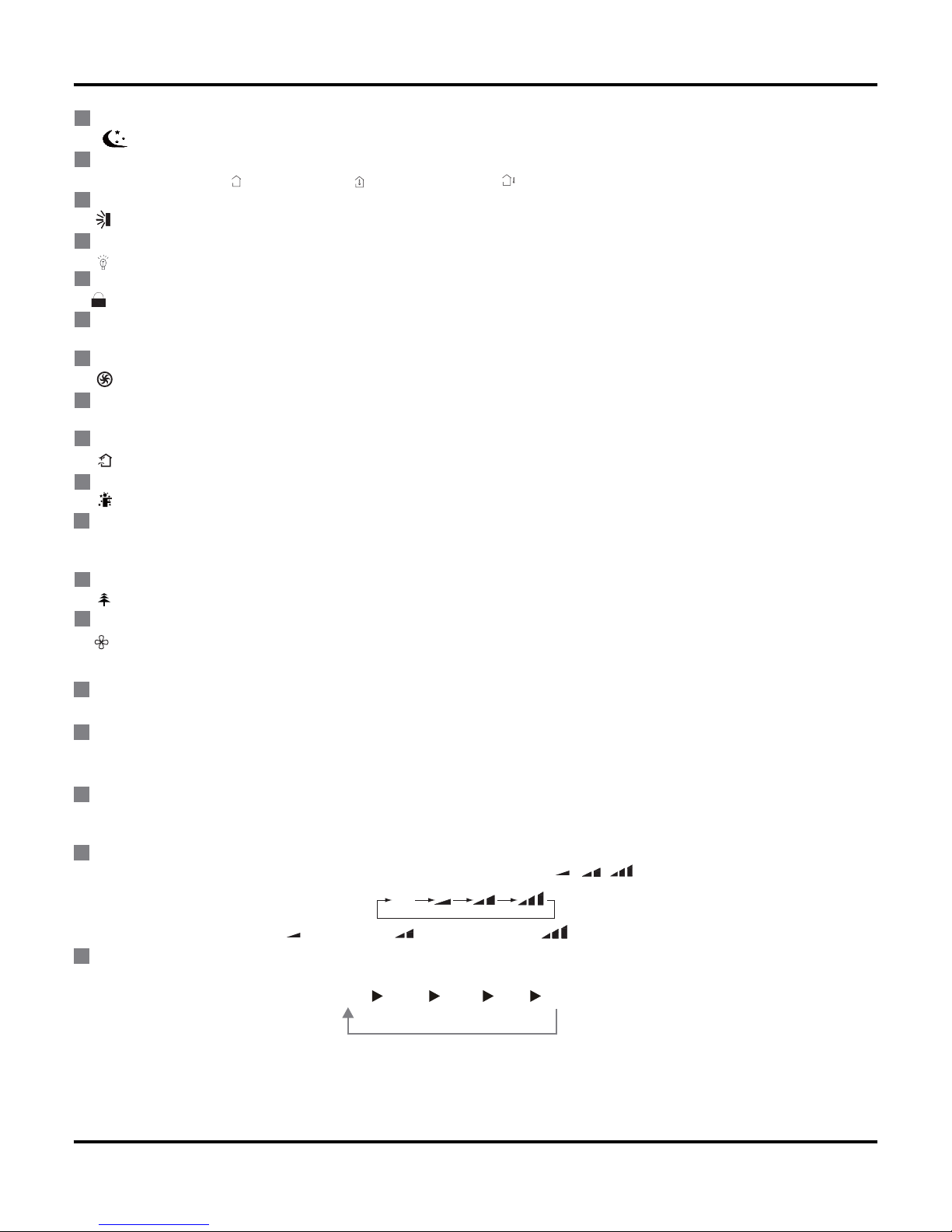
MODE icon:
18
If MODE button is pressed, current operation mode icon (AUTO), ( COOL), (DRY), (FAN) or (HEAT only for heat pump
models) will show.
(X-FAN is the alternative expression of BLOW for the purpose of understanding.)
12
Function and Control
19
SLEEP icon :
is displayed by pressing the SLEEP button. Press this button again to clear the display.
TEMP icon:
Pressing TEMP button, (set temperature), (ambient temperature), (outdoor ambient temperature) and blank is displayed circularly.
Up & down swing icon:
is displayed when pressing the up & down swing button. Press this button again to clear the display.
LIGHT icon:
is displayed by pressing the LIGHT button. Press LIGHT button again to clear the display.
LOCK icon:
is displayed by pressing "+" and “-” buttons simultaneously. Press them again to clear the display.
SET TIME display:
After pressing TIMER button, ON or OFF will blink.This area will show the set time.
TURBO icon:
is displayed when pressing the TURBO button.Press this button again to clear the display.
DIGITAL display:
This area will show the set temperature. In SAVE mode,"SE" will be displayed. During defrosting operation, “H1” will be displayed.
AIR icon:
is displayed when pressing the AIR button.Press this button again to clear the display.
I FEEL icon:
is displayed when pressing the I FEEL button. Press this button again to clear the display.
FAN SPEED display:
Press FAN button to select the desired fan speed setting (AUTO Low-Med-High).Your selection will be displayed in the LCD windows,
except the AUTO fan speed.
HEALTH icon:
is displayed when pressing the HEALTH button. Press this button again to clear the display.
X-FAN icon:
is displayed when pressing the X-FAN button. Press this button again to clear the display.
21
20
22
23
24
25
26
27
28
29
30
31
1
2
3
4
5
ON/OFF:
Press this button to turn on the unit .Press this button again to turn off the unit.
-:
Press this button to decrease set temperature. Hold it down for above 2 seconds to rapidly decrease set temperature. In AUTO mode, set
temperature is not adjustable.
+:
Press this button to increase set temperature. Hold it down for above 2 seconds to rapidly increase set temperature. In AUTO mode, set tem-
perature is not adjustable.
FAN :
This button is used for setting Fan Speed in the sequence that goes from AUTO, , to then back to Auto.
Low speed Medium speed High speed
MODE :
Each time you press this button, a mode is selected in a sequence that goes from AUTO,COOL,DRY, FAN,and HEAT *, as the following:
*Note: Only for models with heating function.
After energization, AUTO mode is defaulted. In AUTO mode, the set temperature will not be displayed on the LCD, and the unit will automati-
cally select the suitable operation mode in accordance with the room temperature to make indoor room comfortable.
,
AUTO
AUTO COOL DRY FAN HEAT *
13
Function and Control
6
8
7
9
10
11
12
13
14
15
16
17
I FEEL:
Press this button to turn on I FEEL function. The unit automatically adjust temperature according to the sensed temperature. Press this button
again to cancel I FEEL function.
Press this button to set HEALTH function ON or OFF. After the unit is turned on, it defaults to HEALTH function ON.
Press this button to select AIR function ON or OFF.
CLOCK :
Pressing CLOCK button, blinks. Within 5 seconds, pressing + or - button adjusts the present time. Holding down either button above 2
seconds increases or decreases the time by 1 minute every 0.5 second and then by 10 minutes every 0.5 second. During blinking after
setting, press CLOCK button again to confirm the setting, and then will be constantly displayed.
TIMER ON :
Press this button to initiate the auto-ON timer. To cancel the auto-timer program, simply press this button again.
After pressing this button, disappear sand " ON " blink s . 00:00 is displayed for ON time setting. Within 5 seconds, press + or - button to
adjust the time value. Every press of either button changes the time setting by 1 minute. Holding down either button rapidly changes the time
setting by 1 minute and then 10 minutes. Within 5 seconds after setting, press TIMER ON button to confirm.
Press this button to set up & down swing angle, which circularly changes as below:
This remote controller is universal. If any command , or is sent out, , , the unit will carry out the command as
indicates the guide louver swings as:
X-FAN:
Pressing X -FAN button in COOL or DRY mode, the icon is displayed and the indoor fan will continue operation for 10 min utes in order to
dry the indoor unit even though you have turned off the unit. After energization, X-FAN OFF is defaulted. X-FAN is not available in AUTO,
FAN or HEAT mode.
TEMP:
Press this button, could select displaying the indoor setting temperature or indoor ambient temperature.When the indoor unit firstly power on
it will display the setting temperature, if the temperature's displaying status is changed from other status to" ",displays the ambient temp-
erature, 5s later or within 5s, it receives other remote control signal that will return to display the setting temperature. if the users haven't set
up the temperature displaying status,that will display the setting temperature.
TIMER OFF :
Press this button to initiate the auto-off timer. To cancel the auto-timer program, simply press the button again.TIMER OFF setting is the
same as TIMER ON.
TURBO:
Press this button to activate / deactivate the Turbo function which enables the unit to reach the preset temperature in the shortest time. In
COOL mode, the unit will blow strong cooling air at super high fan speed. In HEAT mode, the unit will blow strong heating air at super high
fan speed.
SLEEP:
Press this button to go into the SLEEP operation mode. Press it again to cancel this function. This function is available in COOL, HEAT (Only
for models with heating function) or DRY mode to maintain the most comfortable temperature for you.
LIGHT:
Press LIGHT button to turn on the display's light and press this button again to turn off the display's light. If the light is turned on, is dis-
played. If the light is tunrned off , disappears.
AUTO
14
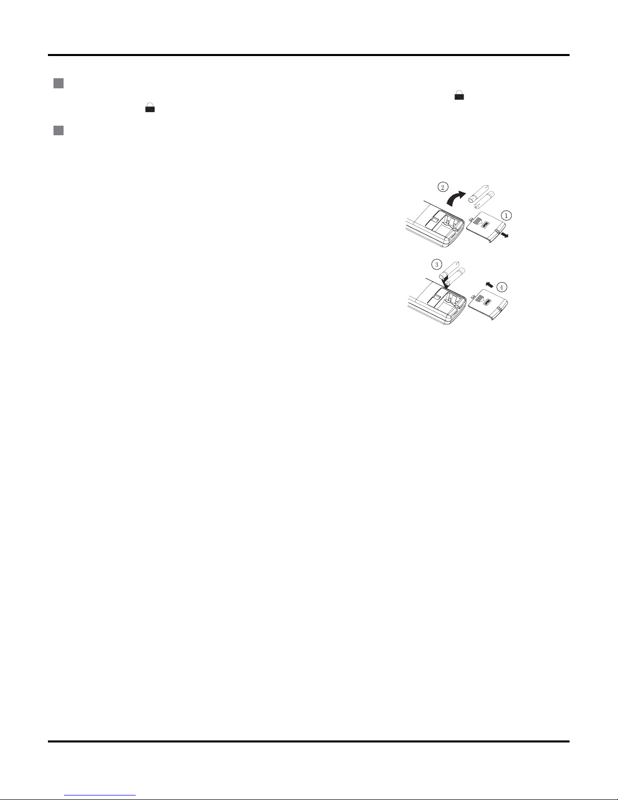
Replacement of Batteries
1.Remove the battery cover plate from the rear of the remote controller.
(As shown in the figure)
2.Take out the old batteries.
3.Insert two new AAA1.5V dry batteries, and pay attention to the polarity.
4. Reinstall the battery cover plate.
★Notes:
●When replacing the batteries, do not use old or different types of batteries,
otherwise, it may cause malfunction.
●If the remote controller will not be used for a long time, please
remove batteries to prevent batteries from leaking.
●The operation should be performed in its receiving range.
●It should be kept 1m away from the TV set or stereo sound sets.
●If the remote controller does not operate normally, please take the
batteries out and reinsert them after 30 seconds. If it still can't operate properly,
replace the batteries.
Sketch map for replacing batteries
18
19
Combination of "+" and "-" buttons: About lock
Press "+ " and "-" buttons simultaneously to lock or unlock the keypad. If the remote controller is locked, is displayed. In this case,
pressing any button, blinks three times.
Combination of "MODE" and "-" buttons: About switch between Fahrenheit and Centigrade At unit OFF, press "MODE" and "- " buttons
℃
and
℉
simultaneously to switch between
Function and Control
15
6.2 Description of Each Control Operation
Function and Control
A
B
C
B
A
Cooling Only
(1) Under this mode, fan and swing run at preset status, the temperature setting range is 16-30ć.
(2) Under malfunction for outdoor unit and protection stop, the indoor unit runs with the original status, and display malfunction.
(3) The indoor fan stops when the modes conflict with each other.
2. Dry Mode
(1) Under this mode, the indoor fan runs with low speed, and swing runs at preset status, the temperature setting range is 16-30
(2) Under malfunction for outdoor unit and protection stop, the indoor unit runs with the original status, and display malfunction.
3. Heating Mode
(1) Under this mode, the temperature setting range is 16-30ć.
(2) Working condition and Process of Heating
When the unit is ON and in heating mode, indoor fan starts cold air prevention operation; when the unit is off and the
indoor fan stopped before, it blows residual heat.
(3) Protection Function. The compressor stops as the malfunction (including any temperature sensor malfunction) in
heating mode, the indoor fan runs with blowing residual heat.
ć.
4. Working Methods of Auto Mode
1) When Tamb.≥26ć , it operates in Cool mode.
2) For heat pump unit, when Tamb.≤22ć, it operates in Heat mode.
3) When 22ć< Tamb.< 26ć, it operates in auto fan mode upon initial startup of the unit. When changing to auto mode from
other modes, it will keep the previous operation mode (when it enter Dry mode, it operates in auto fan mode.).
5. Fan Mode
Only indoor fan operates in Fan mode. Under auto fan speed, it runs in cooling auto fan mode.
I. Basic Operation Mode
1. Cool; 2.Dry; 3.Heat; 4.Auto; 5.Fan
II. Basic Functions
indoor temperature---target temperature
target temperature---indoor temperature
( F)
16
Function and Control
Tset
Tset+1℃
Tset+2℃
Tset+3℃
1H 2H 3H 4H
Tset
1H 2H 3H 4H
Tset-1℃
Tset-2℃
Tset-3℃
1. Buzzer
The buzzer will give out a beep when the controller is energized, receiving signal from remote controller and auto button.
2. Auto Button
Press this button once, it will operate in Auto mode, and indoor fan operates in Auto fan mode and swing. When the unit is on,
pressing this button will turn off the unit.
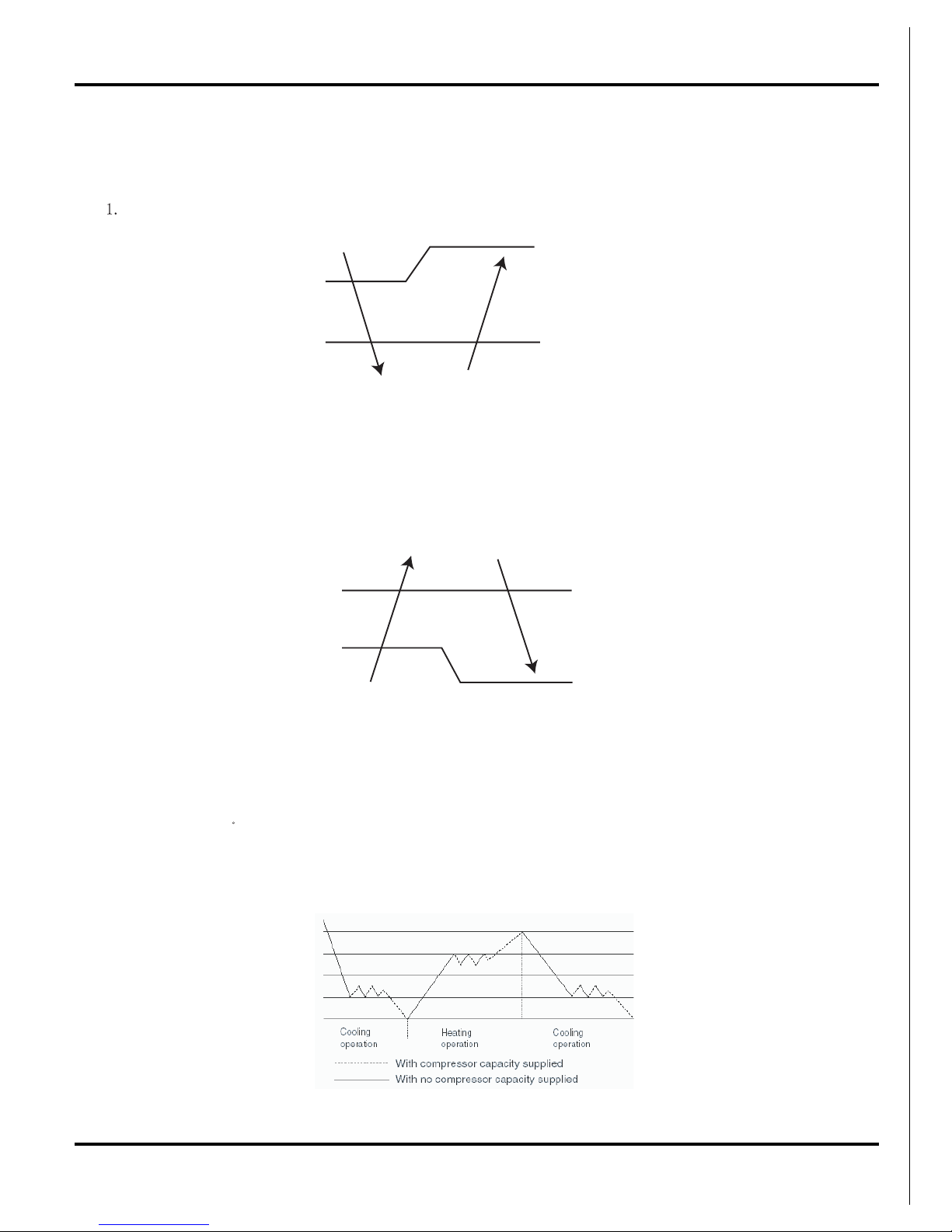
3. Auto Fan
a. Auto fan speed in Heat mode
When Tamb.≤Tpreset, the indoor fan operates at high speed;
When Tpreset<Tamb.<Tpreset+2ć, the indoor fan operates at middle speed;
When Tamb≥Tpreset+2ćˈthe indoor fan operates at low speed.
b. Auto fan speed in CooL and Fan mode
When Tamb≥Tpreset+3ćˈthe indoor fan operates at high speed;
When Tpreset<Tamb.<Tpreset+3ć, the indoor fan operates at middle speed;
When Tamb.≤Tpreset+1 , the indoor fan operates at low speed.
c. The auto fan speed is at low speed in Dry mode.
Note: Under auto fan speed, it will shift between high speed and middle speed, middle speed and low speed, high speed
and low speed, the operation time must be 3.5min at least.
ć
4. Sleep
5. Timer Function
(1) General Timer:
1.1 Time On: if Timer On is set when the system is,the controller will operate in the original setting mode after reaching the
timer on time. The timer interval is 0.5h, and the setting range is 0.5-24h.
1.2 Timer Off: Timer Off can be set when the unit is on. The unit will be off when timer off time is reahced. The timer
interval is 0.5h, and the setting range is 0.5-24h.
(2) Clock Timer:
2.1 Timer On: If Timer On is set when the system runs, it will continue to run; if Timer On is set when the system is off, the
system will start to run in the original setting mode when timer on time is reached.
2.2 Timer Off: If timer off is set when the system is off, the system keeps stand-by status; if timer off is set when the system
is on, the system stops when reaching timer off time.
III. Other Control
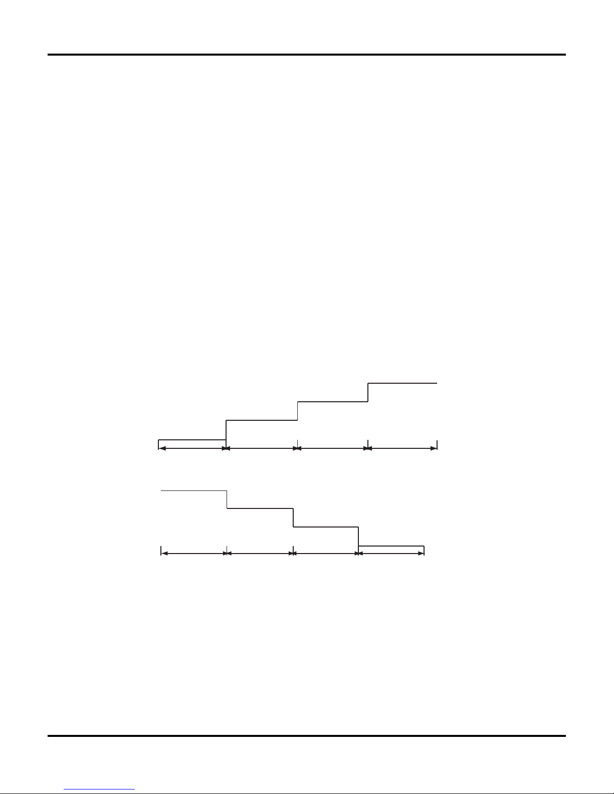
4.1 The unit will select suitable sleep curve according to set temperature.
4.2 Sleep curve in Heat mode
4.3 Sleep curve in Cool mode
 Loading...