

Gree GWC05MA-K1NNA9A, GWH12MB-K1NNA1A, GWH09MA-K1NNA1A, GWC12MB-K1NNA1A, GWC09MA-K1NNA1B Service Manual
...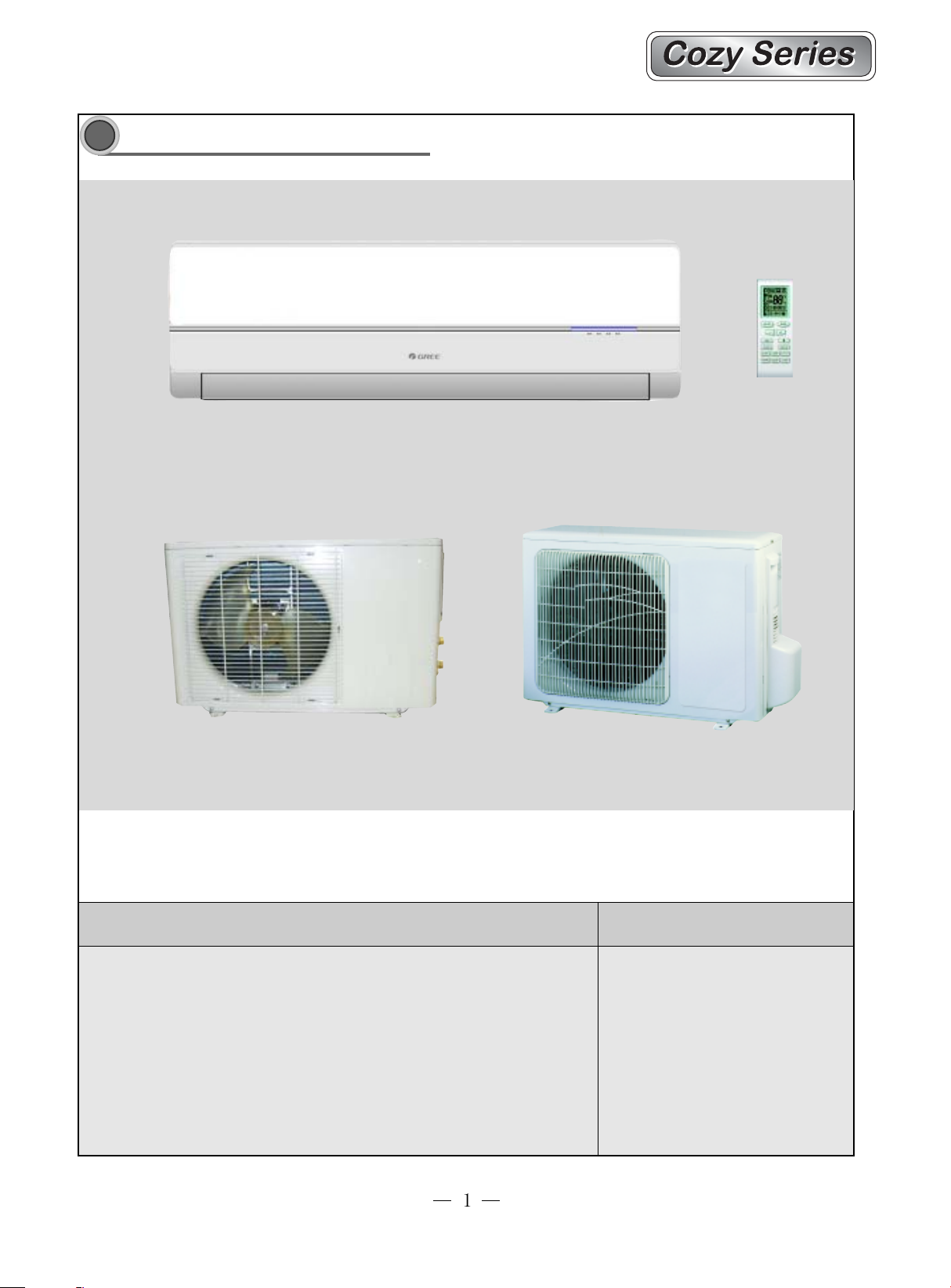
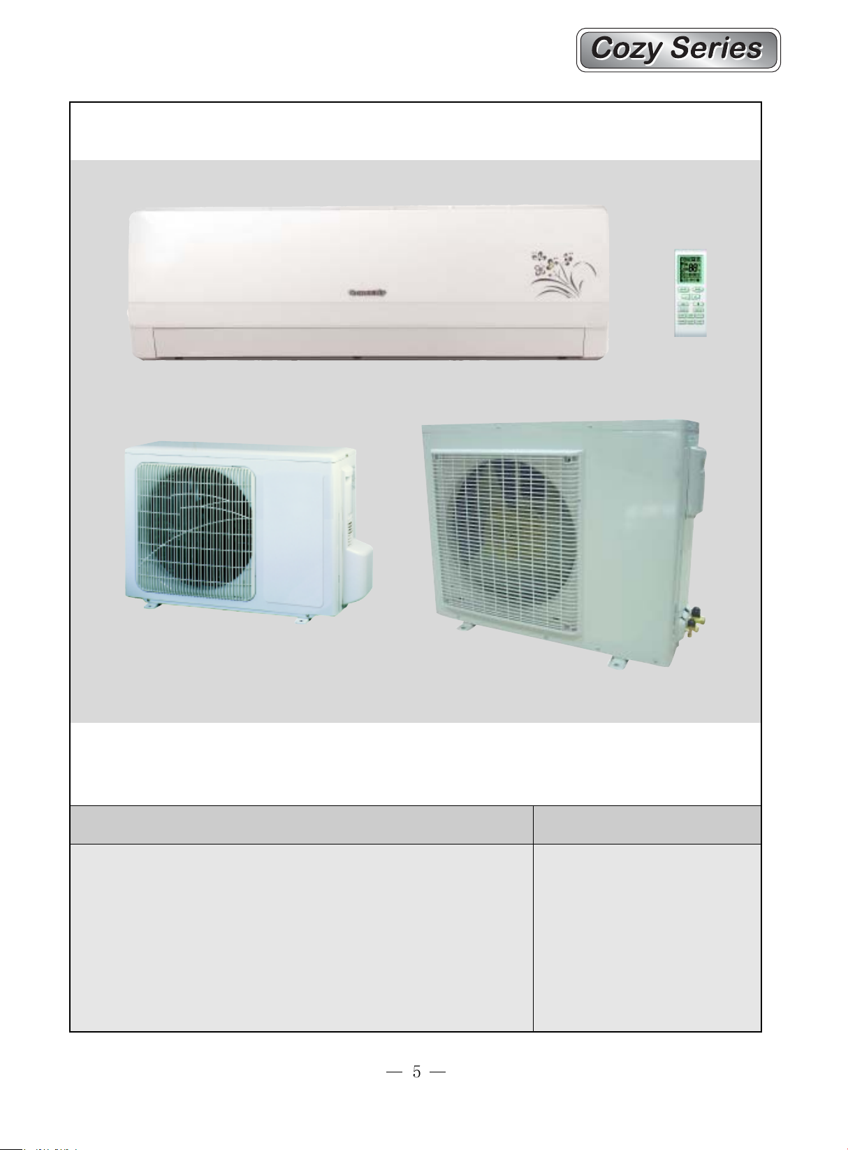
Summary and features
1
Summary and features
07/09K Outdoor unit:05K Outdoor unit:
Model
GWC05MA-K1NNA9A
GWC07MA-K1NNA9A
GWC09MA-K1NNA9A
Remarks
1Ph 220-240V~ 50Hz
R22
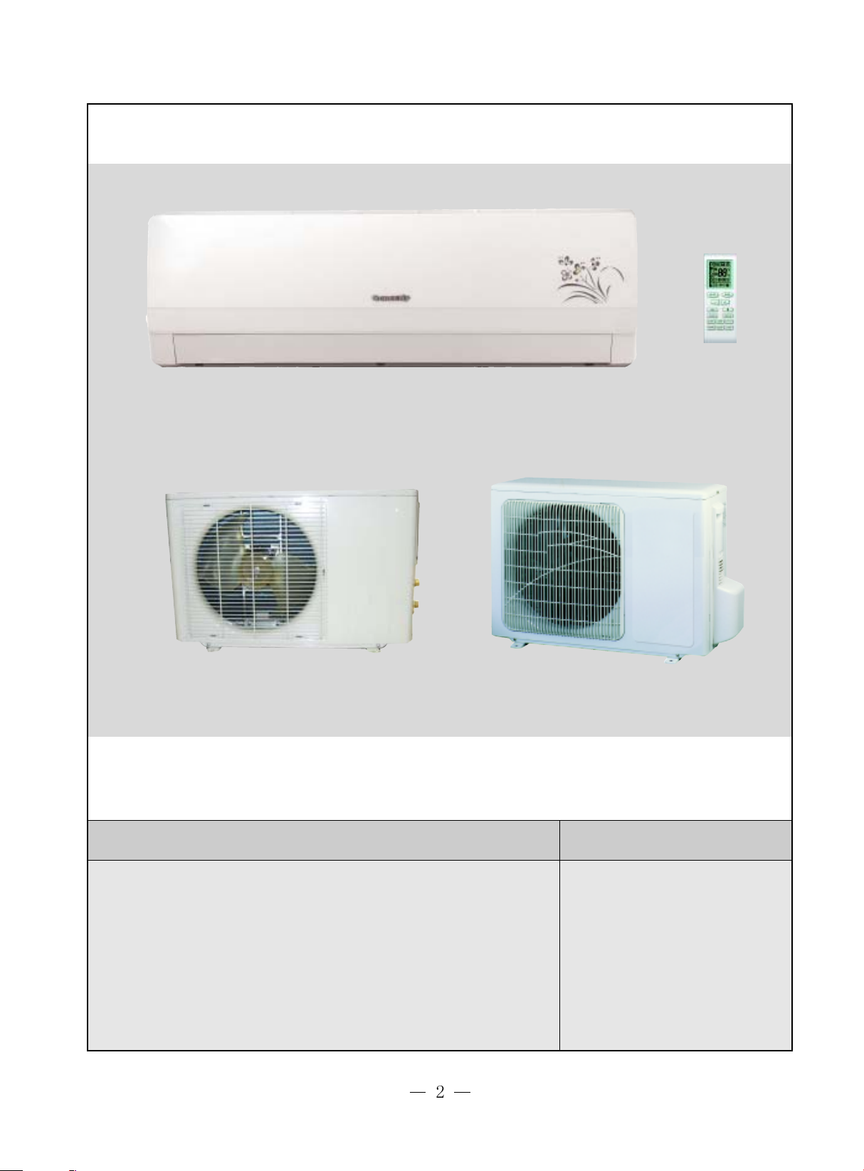
12K Outdoor unit:09K Outdoor unit:
Model
GWC09MA-K1NNA1A
GWH09MA-K1NNA1A
GWC12MB-K1NNA1A
GWH12MB-K1NNA1A
GWC09MA-K1NNA1B
GWC12MB-K1NNA1B
Remarks
1Ph 220-240V~ 50Hz
R22
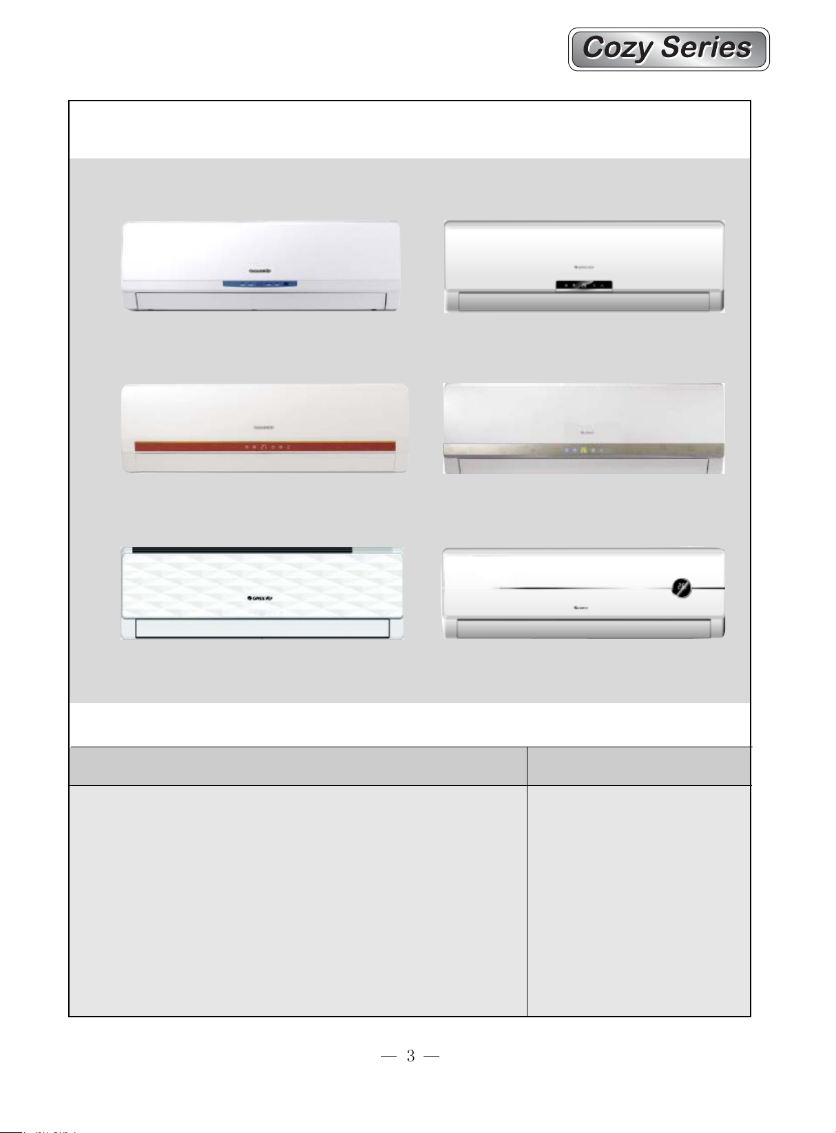
A3 PanelA2 Panel
A4 Panel
A7 Panel
A5 Panel
A8 Panel
Model
GWC09MA-K1NNA2A GWH09MA-K1NNA2A GWC12MB-K1NNA2A
GWH12MB-K1NNA2A GWC09MA-K1NNA3A GWH09MA-K1NNA3A
GWC12MB-K1NNA3A GWH12MB-K1NNA3A GWC09MA-K1NNA3B
GWC12MB-K1NNA3B GWC09MA-K1NNA4A GWH09MA-K1NNA4A
GWC12MB-K1NNA4A GWH12MB-K1NNA4A GWC09MA-K1NNA5A
GWH09MA-K1NNA5A GWC12MB-K1NNA5A GWH12MB-K1NNA5A
GWC09MA-K1NNA8A GWH09MA-K1NNA8A GWC12MB-K1NNA8A
GWH12MB-K1NNA8A GWC12MB-K1NNA7A GWC12MB-K1NNA7B
GWC12MB-K1NNA8B GWC09MA-K1NNA5B
Remarks
1Ph 220-240V~ 50Hz
R22
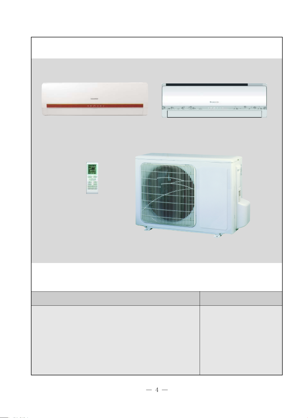
A4 Panel A5 Panel
Model
GWC18MB-K1NNA4A
GWH18MB-K1NNA4A
GWC18MB-K1NNA5A
GWH18MB-K1NNA5A
Remarks
1Ph 220-240V~ 50Hz
R22
Cool only Outdoor unit
Cool and Heat Outdoor unit
Model
GWC18MC-K1NNA1A
GWH18MC-K1NNA1A
Remarks
1Ph 220-240V~ 50Hz
R22
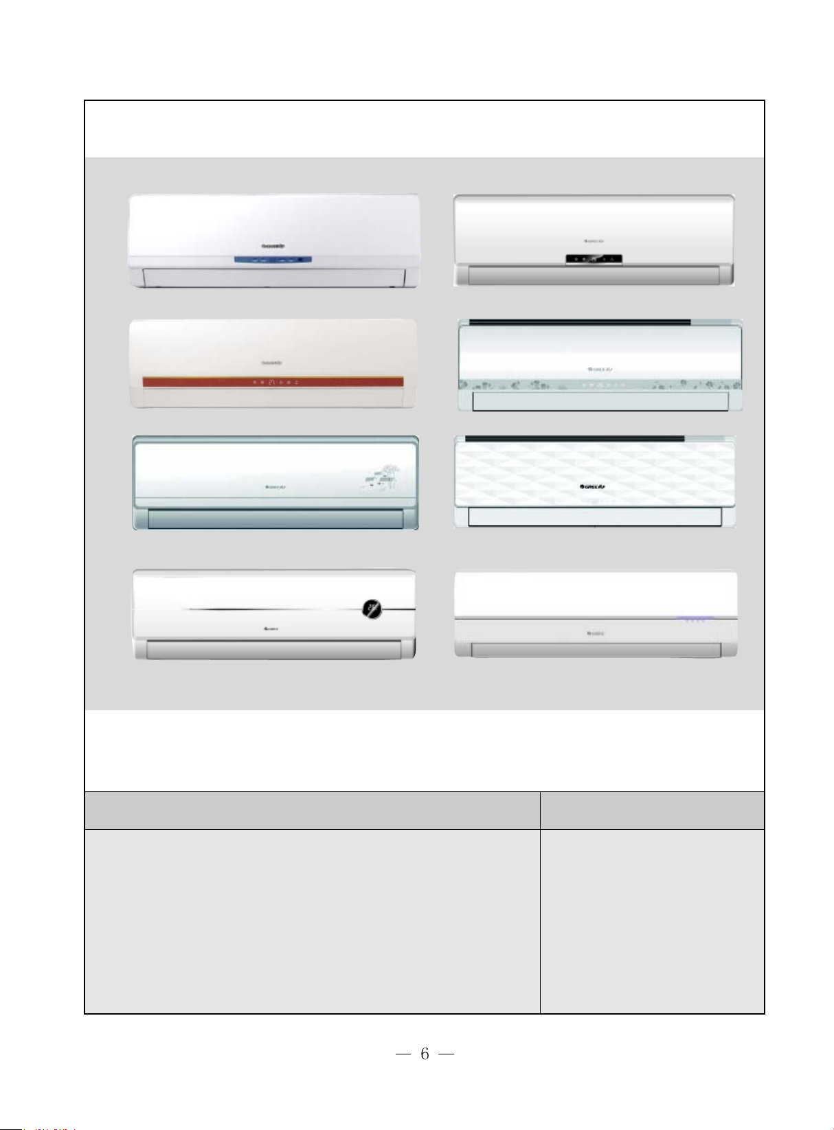
A2 Panel
A3 Panel
A4 Panel
A6 Panel
A8 Panel
A5 Panel
A7 Panel
A9 Panel
Model
GWC18MC-K1NNA2A GWH18MC-K1NNA2A
GWC18MC-K1NNA3A GWH18MC-K1NNA3A
GWC18MC-K1NNA4A GWH18MC-K1NNA4A
GWC18MC-K1NNA5A GWH18MC-K1NNA5A
GWC18MC-K1NNA6A GWH18MC-K1NNA6A
GWC18MC-K1NNA7A GWH18MC-K1NNA7A
GWC18MC-K1NNA8A GWH18MC-K1NNA8A
GWC18MC-K1NNA9A GWH18MC-K1NNA9A
Remarks
1Ph 220-240V~ 50Hz
R22
g
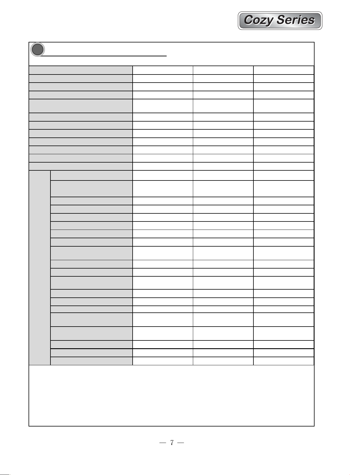
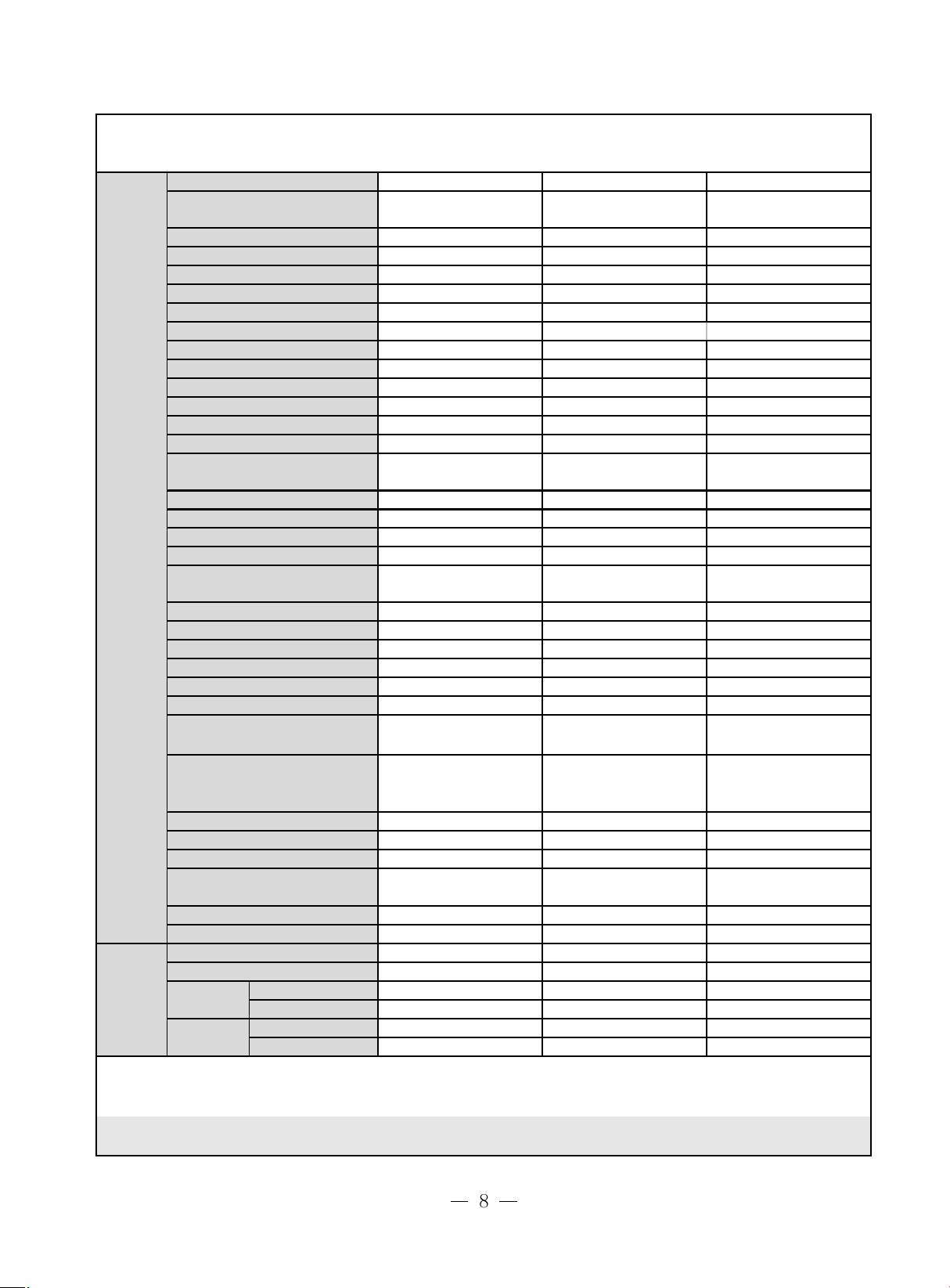
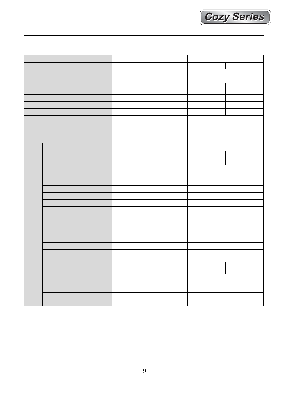
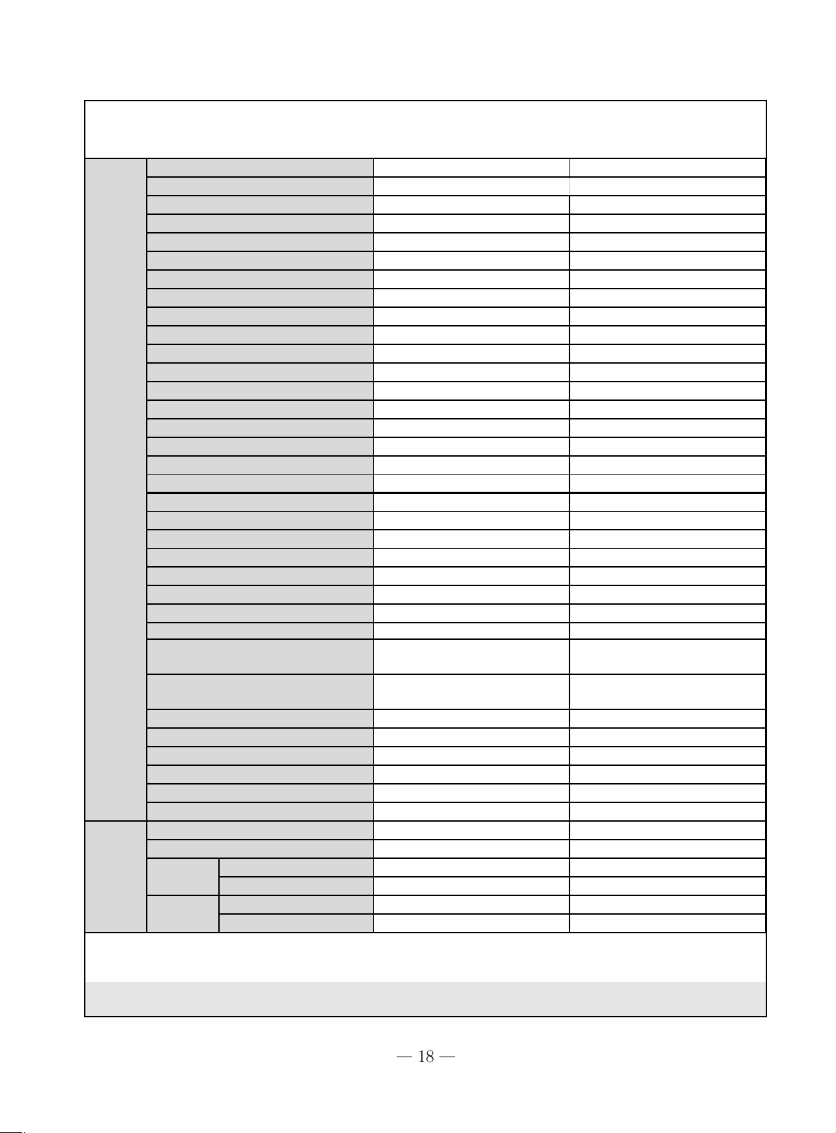
Technical specifications
Technical specifications
2
Model
Function
Rat ed Voltage
Rat ed F r equenc y
Total Capacity (W/Btu/h)
Power Input (W)
Rat ed I nput (W)
Rat ed Curr ent (A )
3
A ir Flow Volume (m
Dehumidifying Volume (l/h)
EER / C.O.P (W / W )
Ener gy Class
Model of I ndo or Uni t GWC05MA-K1NNA9A /I GWC07MA-K1NNA9A /I GWC09MA-K1N NA9A /I
Fan Motor Speed ( r /min) ( H/M/L) 1260/1 050/920/730 1260/ 1050/920/730 1260/ 1050/920/730
Output of Fan Mot o r (w) 10 10 10
Input of Heater (w )
Fan Motor Capacitor (uF) 1 1 1
Fan Motor RLA (A) -- -- -Fan Ty pe-Piece Cross flow fan - 1 Cross flow fan - 1 Cross flow fan - 1
Diameter- Len gth (mm) Φ85X 596 Φ85X 596 Φ85X 596
Evaporator
Indoor
Pipe Diameter (mm) Φ7 Φ7 Φ7
unit
Row-F i n Gap(mm) 2.- 1 .5 2.-1.5 2.-1.5
Coil len
width (L )
Swing Motor Model MP24AA MP24AA M P24AA
Output of S wing Motor ( W ) 1.5 1.5 1.5
Fuse (A) PCB 3 .15A PCB 3 .15A PCB 3.15A
Sound P ressure Level dB (A )
(H/M/L)
Sound P ower Level dB (A)
(H/M/L)***
Dimension ( W /H/D) ( mm) 790×265× 170 790×265× 170 790×265× 170
Dimension of Pa ckage (W/H/D)(mm)
Net Weight /Gross Weight ( kg) 9/12 9/12 9/12
/h) (H/M /L)**
th (l)×height (H)×coil
GWC05MA-K1NNA9A GWC07MA-K1NNA9A GWC09MA-K1NNA9A
COOLING COOLING
220-240V~ 220-240V~ 220-240V~
50Hz 50Hz 50Hz
1400W 2000W 2500W
380 550 685
500 710 890
1.7 2.6 3.2
500 500 500
0.8 0.8 0.8
3.68/- 3.64/- 3.65////
-- -- --
A lu minum fin-cop per
tube
581X264X25.4 581X264X25.4 581X264X25.4
37/30/26 37/30/26 37/30/26
-- -- --
870X248X355 870X248X355 870X248X355
A l uminum fin-cop per
tube
COOLING
Aluminum fin- c oppe r
tube
Outdoor
(
/h)
unit
Connecti
on Pipe
Model of Outdoor Unit
Compressor
Manufacturer/trademark
Compressor M odel
Compressor Type
L.R.A. (A )
Compressor RLA(A)
Compressor Power I nput(W)
Overload Protec tor
Thr ottling M e t hod
St ar t ing Metho d
Wor k ing Temp Range (℃)
Condenser
Pipe Diameter ( mm)
Rows-Fin Gap(mm)
Coil lengt h( l ) x height ( H ) x coil
width(L)
Fan M otor Speed (rpm) (H/M/L)
Output of Fan Motor (W)
Fan M otor RLA(A )
Fan Motor Capacitor (uF)
A ir Flow Volume of Outdoor
3
Unit
m
Fan Type-Piece
Fan Diamet er ( mm)
Defrosting Method
Climate T ype
Isolation
Moisture Prot ec tion
Permissible Excessive
Oper ating Pressure for the
Permissible Excessive
Oper ating Pressure for the
Suction Side(MPa)
Sound P r essure Level dB (A)
Sound P ower Level dB (A)
Dimension (W/ H/ D) (mm)
Dimension of Package
(L/W/H)(mm)
Net Weight / Gross Weig ht (kg)
Refr ig er an t Charge ( k g)
Length ( m)
Gas addit ion al c ha r ge( g /m)
Outer
Diameter
Ma
x
stance
Di
Liquid Pipe ( mm) Φ6(1/4") Φ6(1/4") Φ6(1/4")
Gas Pipe ( mm) Φ9.52(3/8") Φ9.52(3/8") Φ9.52(3/8")
Height (m)555
Length ( m) 10 10 10
GWC05MA-K1NNA9A/O GWC07MA-K1NNA9A/O GWC09MA-K1NNA9A/O
RECHI P RE CISI ON
CO.,LTD
HITACH I SANYO
39R094AD&5DSB SD104CV-H3AU C-1RV132H41BA
revolving revolving revolving
10.8 13.5 15
1.7 2.75 3.35
365 575 730
MRA12072-12056 BF540-KB MRA99943-
Capillary Capillary Capillary
Capacitor Capacitor Capacitor
18℃≤T≤43
℃
18℃≤T≤43
℃
18℃≤T≤43
℃
Aluminum fin- c oppe r Aluminum fin- c oppe r Aluminum fin- c o pper
Φ7 Φ7 Φ9.52
1-1.4 1-1.4 1-1.6
680X400X12.7
768X495X12.7 760X508X22
950 830 830
20 30 30
0.35 0.37 0.37
1.5 2.5 2.5
1200
1400 1400
Axial fan -1 Axial fan -1 Axial fan - 1
Ф324 Ф400 Ф400
///
T1 T1 T1
III
IP24 IP24 IP24
2.5
2.5 2.5
0.6
0.6 0.6
50 50 50
-- -- -720X430X320 848X540X320 848X540X320
765X350X475
878X580X360 878X580X360
21/24 26/30 29/33
R22/0.43 R22/0.5 R22/0.75
444
30 30 30
The above data is subject to change without notice. Please refer to the nameplate of the unit.
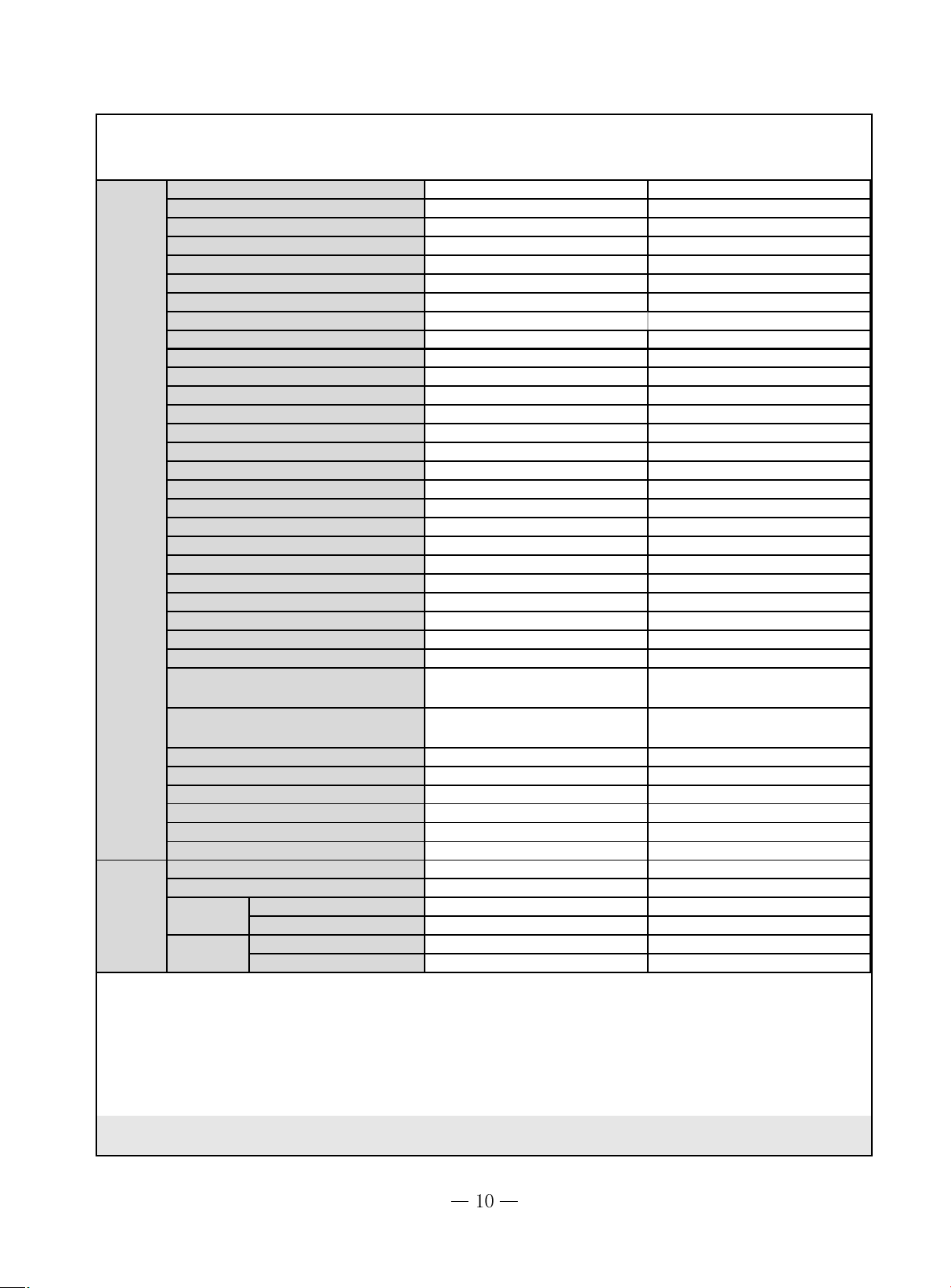
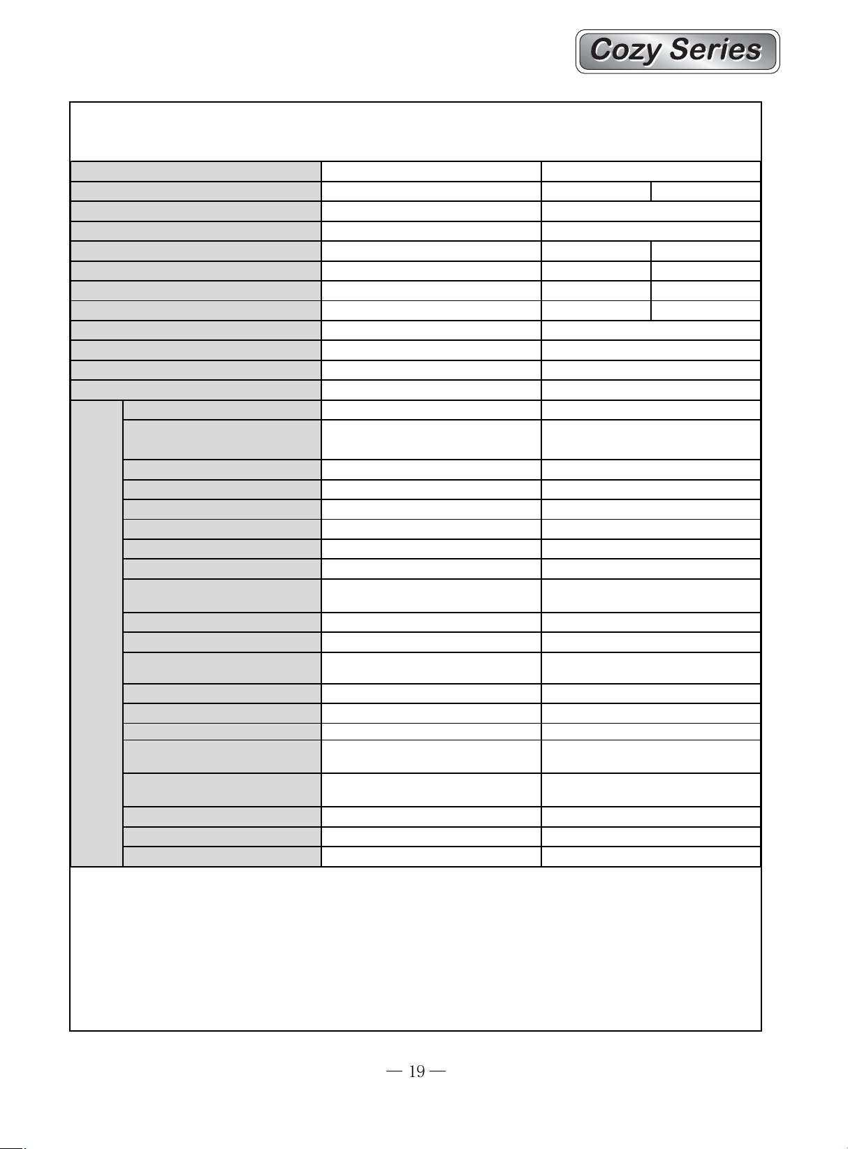
g
Model
Function
Rat ed Voltage
Rat ed Frequency
GWC 09MA-K1NNA*A
COOLING
220-240V~
50Hz
GWH09MA-K1NNA*A
COOLING HEATING
220-240V~
50Hz
Total Capacity (W/Btu/h)
Power Input (W)
Rat ed Input (W )
Rat ed Current (A)
A ir Flow Volume (m
3
/h) (H/M / L)**
Dehumidifying Volume (l/h)
EER / C.O.P (W/W)
Energy Class
Model of In door Unit
Fan Motor Speed (r/min) (H/M/ L)
Output of Fan M otor (w)
Input of Heat er (w)
Fan Motor Capacitor (uF)
Fan M otor RLA(A )
Fan Ty pe-Piece
Diameter- Leng th (mm)
Evaporator
Indoor
Pipe Diamete r ( mm)
unit
Row-Fin Gap(mm)
Coil len
th (l)×height (H)×coil
widt h ( L)
Swing Motor Model
Output of Swing Motor (W)
Fuse (A )
Sound P r essure Level dB (A)
(H/M/L)
Sound P ower Level dB (A)
(H/M/L)***
Dimension (W/ H/ D) ( mm)
Dimension of Package(W/H/D)(mm)
Net Weight /Gross Weight ( k g)
2500
925
1200
5.45
500
0.8
2.7
/
GWC09MA-K1NNA*A/I
1260/1050/920/730
10
-1
--
Cross flow fa n - 1
Φ85X 596
Aluminum fin-copper tube
Φ7
2.-1.5
581×264×25.4
MP24AA
1.5
PCB 3 .15A Transformer 0.2A
37/30/26
--
790×265×170
870×248×355
9/12
2500 2800
925 900
1200 1200
5.45 5.45
500
0.8
2.7
/
GWH09MA-K1NNA*A/I
1260/1050/920/7301320/1200/1100/9
50
10
——
1
——
Cross flow fa n – 1
Φ85X 596
Aluminum fin- c opper tube
Φ7
2.-1.5
581×264×25.4
MP24AA
1.5
PCB 3.15A Transformer 0.2A
37/30/26 37/33/29
——
790×265×170
870×248×355
9/12
Outdoor
unit
Connecti
on Pipe
Model of Out door Unit
Compressor Manufac turer/trademark
Compressor Model
Compressor T ype
L.R . A. (A)
Compressor RLA ( A)
Compressor Power I nput(W)
Overload Pr otector
Throttling Method
Star t ing Method
Wor k i ng Temp Range (℃)
Condenser
Pipe Diameter ( mm)
Rows-Fin Gap(mm)
Coil length(l) x height ( H ) x coil width(L)
Fan Motor Speed (rpm) (H/M/ L)
Output of Fan Motor (W)
n Motor RLA(A)
a
F
Fan Motor Capacitor (uF)
Air Flow Volume of O utdoor Unit
Fan Type-Piec e
Fan Diameter (mm)
Def r osting Method
Climate T ype
Isolation
Moisture Protection
Per missible E xcessive Oper a ting
Pressure for the Discharge Side(MPa)
Per missible E xcessive Oper a ting
Pressure for the Suction Side(M Pa)
Sound Pressure Lev el dB (A ) (H/M/L)
Sound Power Lev el dB (A) (H/M/L)
Dimension ( W/H/D ) ( mm)
Dimension of P ac k age ( L/ W/H)( mm)
Net Weight /Gross Weight ( k g)
Ref r igerant Charge (k g)
Lengt h ( m)
Gas addit i onal charge(g /m)
Outer
Diameter
Max
Distance
Liquid Pipe ( mm) Φ6(1/4") Φ6(1/4")
Gas Pipe ( mm) Φ9.52(3/8") Φ9.52(3/8")
Height ( m) 5 5
Lengt h ( m) 10 10
GWC09MA-K1NNA3A/O GWH09MA-K1NNA3A/O
LANDA LANDA
QX-B16A030 QX-B16A030
revo lving revo l ving
21 21
4.1 4.1
880 880
Internal Internal
Capillary Capillary
Capacitor Capacitor
-7℃≤T≤48
A luminum fin-copper t ube A luminum fin-c opper tube
1-1.4 1-1.4
680X400X12.7 680X406X22
2500 2500
Axial fan -1 Axial fan -1
Ф324 Ф324
720X430X320 720X430X320
765X350X490 765X350X490
25/29 25/29
R22/0.52 R22/0.63
℃
Φ7 Φ9.52
950 950
20 20
0.13 0.13
1.5 1.5
//
T1 T1
II
IP24 IP24
2.5 2.5
0.6 0.6
50 50
-- --
44
30 30
-7℃≤T≤48
℃
The above data is subject to change without notice. Please refer to the nameplate of the unit.

g
Model
Function
Rat ed Voltage
Rat ed F r equen cy
GWC09MA-K1NNA1B、GWC09MA-K1NNA3B 、GWC09MA-K1NNA8A
COOLING
220-240V~
50Hz
Total Capacity (W/Btu/h)
Power Input (W)
Rat ed I nput (W)
Rat ed Cur rent (A )
3
A ir Flow Volume (m
/h) (H/M/L)**
Dehumidifying V olume (l/ h)
EER / C.O.P (W / W )
Ener gy Class
Model of I ndo or Uni t
Fan Motor Speed ( r /min) ( H/M/L)
Output of Fan Motor (w)
Input of Heater (w)
Fan Motor Capacitor (uF)
Fan Motor RLA(A)
Fan Type-Piece
Diameter- Le ngth (mm)
Evaporator
Indoor
Pipe Diamet er (mm)
unit
Row-F in Gap(mm)
Coil len
th (l)×height (H)×coil
width (L)
Swing Motor Model
Output of S w ing Motor (W )
Fuse (A)
Sound P r essure Level dB (A)
(H/M/L)
Sound P ower Level dB (A)
(H/M/L)***
Dimension (W/H/D) ( mm)
D im e nsio n of P a ckage (W/H/D)(m m)
Net Weight /Gross Weight ( k g )
9000 Btu/h
798W
1080W
5
500(H)
0.8
3.21/3.3
A
GWC09MA-K1NNA1B/I、GWC09MA-K1NNA3B/I、GWC09MA-K1NNA8A/I
Cooling:1260/1050/920/730
10
/
1
0.1
Cross flow fan – 1
φ85×596
A lu minum fin-cop per t ube
Φ7
2-1.5
581X264X25.4
MP24AA
1.5
PCB 3.15A Transformer 0. 2A
38/36/33
48/46/43
790×265×170
870×248×355
9/12
Outdoor
unit
Connecti
on Pipe
Model of O utdoor Unit
Compressor Manufac turer/ trademark
Compressor M odel
Compressor Type
L.R.A. (A )
Compressor RLA(A)
Compressor Power Input(W)
Overload Protector
Throttling Method
St ar ting M ethod
Wor k in g Temp Range (℃)
Condenser
Pipe Diamete r ( mm)
Rows-Fin Gap( mm)
Coil lengt h( l ) x height ( H ) x coil width(L)
Fan Motor Speed (rpm) (H/M/ L)
Out put of Fan Motor (W)
Fan Motor Capacitor (uF)
Air Flow Volume of Outdoor Unit
Fan Ty pe-Piece
Fan Diamet e r ( mm)
Defrosting Method
Climate Type
Isolation
Moist ure P r otection
P ermi ssible Excessive Oper ating
Pressure for t he Dischar ge Si de( MPa)
P ermi ssible Excessive Oper ating
Pressure for the Suction Side(MPa)
Sound P r essure Level dB (A) (H/ M/L)
Sound Power Level dB (A) (H/M/L)
Dimension (W/ H/D) (mm)
Dimension of Package (L/W/H)(mm)
Net Weight / Gross Weight (kg)
Refr ig er an t Charge (kg)
Length ( m)
Gas addit ion al c h ar ge(g/m)
Outer
Diameter
Max
Distance
Liquid Pipe (mm)
Gas Pipe (mm)
Height (m)
Length ( m)
GWC09MA-K1NNA1B/O
MATSUSHITA-WANBAO
2P16S225AN C
ROTARY
18
3.9
840
MRA99200
Capillary
Capacitor
16-30?C/-7-48?C
Aluminum fin- c oppe r tube
Φ7.94
2-1.4
616×210×508
850
30
0.23Fan M otor RLA(A )
2
1500
Axial fan -1
Φ400
/
T1
I
IP24
2.5
0.6
50
60
848×540×320
878×360×580
34/37
R22/1020
4
30
Φ6(1/4")
Φ9.52(3/8")
10
20
The above data is subject to change without notice. Please refer to the nameplate of the unit.
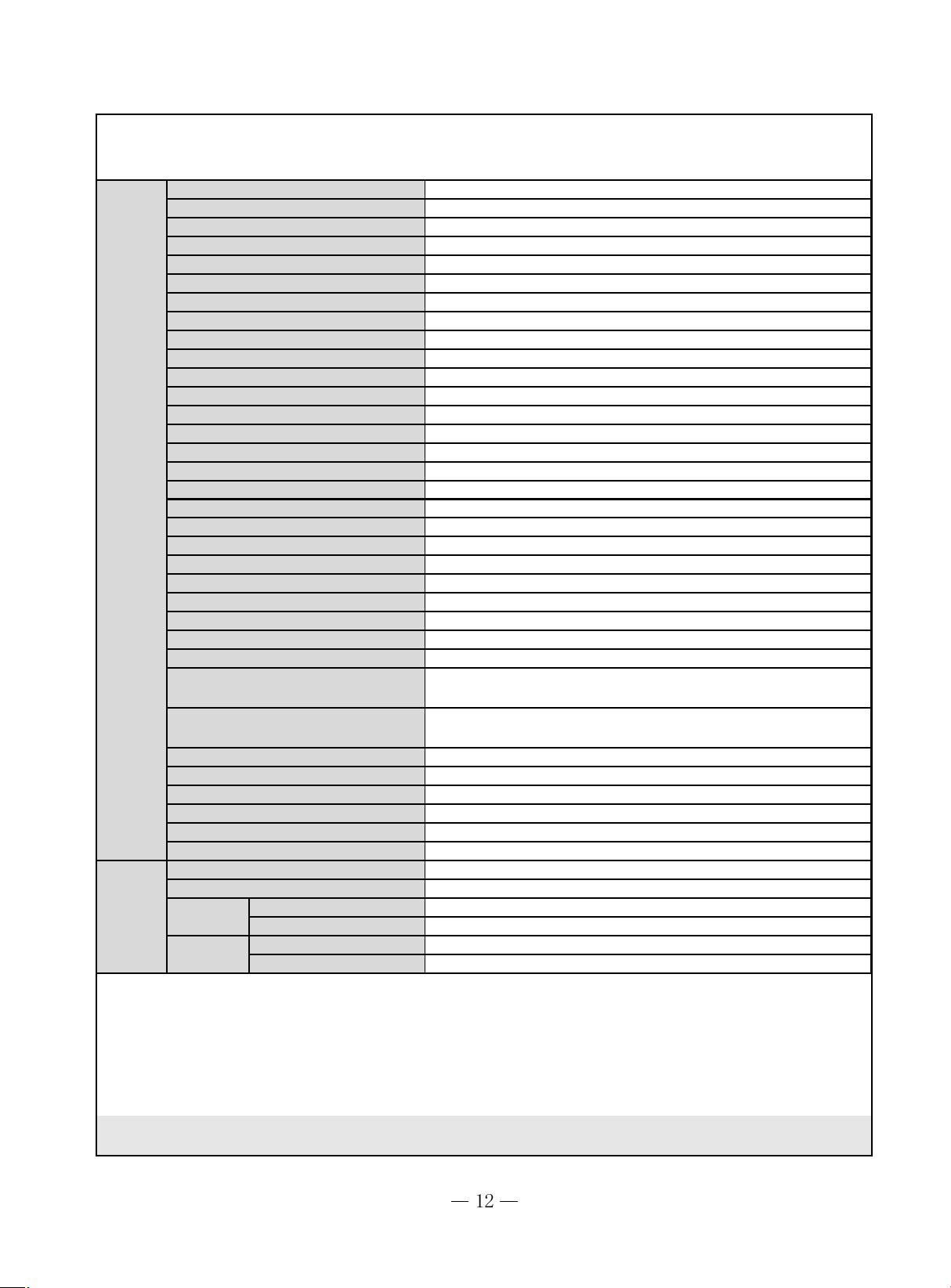
g
Model
Function
Rat ed Voltage
Rat ed F r equen cy
Total Capacity (W/Btu/h)
Power Input (W)
Rat ed I nput (W)
Rat ed Cur rent (A )
3
A ir Flow Volume (m
/h) (H/M/L)**
Dehumidifying V olume (l/ h)
EER / C.O.P (W / W )
Ener gy Class
Model of I ndo or Uni t
GWC12MB-K1NNA*A
COOLING
220-240V~
50Hz
3516(12000)
1290
1600
8.6
(630)/530/430/330
1.2
2.73
1
星
GWC12MB-K1NNA*A/I
GWH12MB-K1NNA*A
COOLING HEATING
220-240V~
50Hz
3516(12000) 3750(12800)
1290 1130
1600 1600
8.6 8.6
(630)/530/430/330
1.2
2.73
1
星
GWH12MB-K1NNA*A/I
Indoor
unit
Fan Motor Speed ( r /min) ( H/M/L)
Output of Fan Motor (w)
Input of Heater (w)
Fan Motor Capacitor (uF)
Fan Motor RLA(A)
Fan Type-Piece
Diameter- Le ngth (mm)
Evaporator
Pipe Diamet er (mm)
Row-F in Gap(mm)
Coil len
th (l)×height (H)×coil
width (L)
Swing Motor Model
Output of S w ing Motor (W )
Fuse (A)
Sound P r essure Level dB (A)
(H/M/L)
Sound P ower Level dB (A)
(H/M/L)***
Dimension (W/H/D) ( mm)
D im e nsio n of P a ckage (W/ H/D)(mm)
Net Weight /Gross Weight ( k g )
(1260)/1070/900/730
20
/
1
0.254
Cross flow fan - 1
φ92 X 645
A l uminum fin-co pper t ube
7
2-1.4
645X25.4X267
MP24AA
2.4
PCB 3.15A Transformer 0.2A
(41)38/34/29
(51)48/44/39
845×275×180
915×255×355
10/13
(1260)/1070/900/730
20
/
1
0.254
Cross flow f an - 1
φ92 X 645
Aluminum fin- c opp er tube
7
2-1.4
645X25.4X267
MP24AA
2.4
PCB 3 .15A Transformer 0.2 A
(41)38/34/29
(51)48/44/39
845×275×180
915×255×355
10/13

Outdoor
unit
Connecti
on Pipe
Model of Out door Unit
Compressor Manufac turer/trademark
Compressor Model
Compressor T ype
L.R . A. (A)
Compressor RLA ( A)
Compressor Power I nput(W)
Overload Pr otector
Throttling Method
Star t ing Method
Wor k i ng Temp Range (℃)
Condenser
Pipe Diameter ( mm)
Rows-Fin Gap(mm)
Coil length(l) x height ( H ) x coil width(L)
Fan Motor Speed (rpm) (H/M/ L)
Output of Fan Motor (W)
Fan Motor RLA(A)
Fan Motor Capacitor (uF)
Air Flow Volume of O utdoor Unit
Fan Type-Piec e
Fan Diameter (mm)
Def r osting Method
Climate T ype
Isolation
Moisture Protection
Per missible E xcessive Oper a ting
Pressure for the Discharge Side(MPa)
Per missible E xcessive Oper a ting
Pressure for the Suction Side(M Pa)
Sound Pressure Lev el dB (A ) (H/M/L)
Sound Power Lev el dB (A) (H/M/L)
Dimension ( W/H/D ) ( mm)
Dimension of P ac k age ( L/ W/H)( mm)
Net Weight /Gross Weight ( k g)
Ref r igerant Charge (k g)
Lengt h ( m)
Gas addit i onal charge(g /m)
Outer
Diameter
Max
Distance
Liquid Pipe ( mm) Φ6(1/4") Φ6(1/4")
Gas Pipe ( mm) Φ12(1/2") Φ12(1/2")
Height ( m) 5 5
Lengt h ( m) 10 10
GWC12MB-K1NNA3A/O GWH12MB-K1NNA3A/O
LAMDA LAMDA
QX-21E030gB QX-21E030gB
Rotory Rotory
30 30
5.7 5.7
1170 1170
B250- 150A-141E or HP A-730 or UP 3QE0594-T56
Capillary Capillary
Capacitor Capacitor
-7~43 -7~43
A luminum fin-copper t ube A luminum fin-c opper tube
77.94
1-1.4 1-1.4
731×495×12.7 749×506×19.05
850 850
30 30
0.35 0.35
22
1700 1700
Axial fan -1 Axial fan -1
400 400
A uto def rost Aut o def r ost
T1 T1
II
IP24 IP24
2.5 2.5
0.6 0.6
51 51
61 61
848×540×320 848×540×320
878×360×590 878×360×590
35/40 35/40
R22/0.60 R22/0.80
55
25 25
The above data is subject to change without notice. Please refer to the nameplate of the unit.

g
Model
Function
Rat ed Voltage
Rat ed F r equen cy
GWC12MB-K1NNA*B
COOLING
220-240V~
50Hz
Total Capacity (W/Btu/h)
Power Input (W)
Rat ed I nput (W)
Rat ed Cur rent (A )
3
A ir Flow Volume (m
/h) (H/M/L)**
Dehumidifying V olume (l/ h)
EER / C.O.P (W / W )
Ener gy Class
Model of I ndo or Uni t
Fan Motor Speed ( r /min) ( H/M/L)
Output of Fan Motor (w)
Input of Heater (w)
Fan Motor Capacitor (uF)
Fan Motor RLA(A)
Fan Type-Piece
Diameter- Le ngth (mm)
Evaporator
Indoor
Pipe Diamet er (mm)
unit
Row-F in Gap(mm)
Coil len
th (l)×height (H)×coil
width (L)
Swing Motor Model
Output of S w ing Motor (W )
Fuse (A)
Sound P r essure Level dB (A)
(H/M/L)
Sound P ower Level dB (A)
(H/M/L)***
Dimension (W/H/D) ( mm)
D im e nsio n of P a ckage (W/H/D)(m m)
Net Weight /Gross Weight ( k g )
3516W(12000Btu/h)
1065
1450
8
(630)/530/430/330
1.2
3.3
5
星
GWC12MB-K1NNA*B/I
(1260)/1070/900/730
20
/
1
0.254
Cross flow fan - 1
φ92 X 645
A lu minum fin-cop per t ube
7
2-1.4
645X25.4X267
MP24AA
2.4
PCB 3.15A Transformer 0. 2A
(41)38/34/29
(51)48/44/39
845×275×180
915×255×355
10/13

Outdoor
unit
Connecti
on Pipe
Model of O utdoor Unit
Compressor Manufac turer/ trademark
Compressor M odel
Compressor Type
L.R.A. (A )
Compressor RLA(A)
Compressor Power Input(W)
Overload Protector
Throttling Method
St ar ting M ethod
Wor k in g Temp Range (℃)
Condenser
Pipe Diamete r ( mm)
Rows-Fin Gap( mm)
Coil lengt h( l ) x height ( H ) x coil width(L)
Fan Motor Speed (rpm) (H/M/ L)
Out put of Fan Motor (W)
Fan M otor RLA(A )
Fan Motor Capacitor (uF)
Air Flow Volume of Outdoor Unit
Fan Ty pe-Piece
Fan Diamet e r ( mm)
Defrosting Method
Climate Type
Isolation
Moist ure P r otection
P ermi ssible Excessive Oper ating
Pressure for t he Dischar ge Si de( MPa)
P ermi ssible Excessive Oper ating
Pressure for the Suction Side(MPa)
Sound P r essure Level dB (A) (H/ M/L)
Sound Power Level dB (A) (H/M/L)
Dimension (W/ H/D) (mm)
Dimension of Package (L/W/H)(mm)
Net Weight / Gross Weight (kg)
Refr ig er an t Charge (kg)
Length ( m)
Gas addit ion al c h ar ge(g/m)
Outer
Diameter
Max
Distance
Liquid Pipe (mm)
Gas Pipe (mm)
Height (m)
Length ( m)
GWC12MB-K1NNA1B/O
MGC
RS211VSDC
Rotory
23/25
5.1/5.0
1110/1150
Internal
Capillary
Capacitor
-7~48
Aluminum fin- c oppe r tube
9.52
2-1.4
731×495×12.7
850
30
0.35
2
1700
Axial fan -1
400
A u t o defrost
T1
I
IP24
2.5
0.6
51
61
848×540×320
878×360×580
38/43
R22/1.2
5
25
Φ6(1/4")
Φ12(1/2")
5
10
The above data is subject to change without notice. Please refer to the nameplate of the unit.

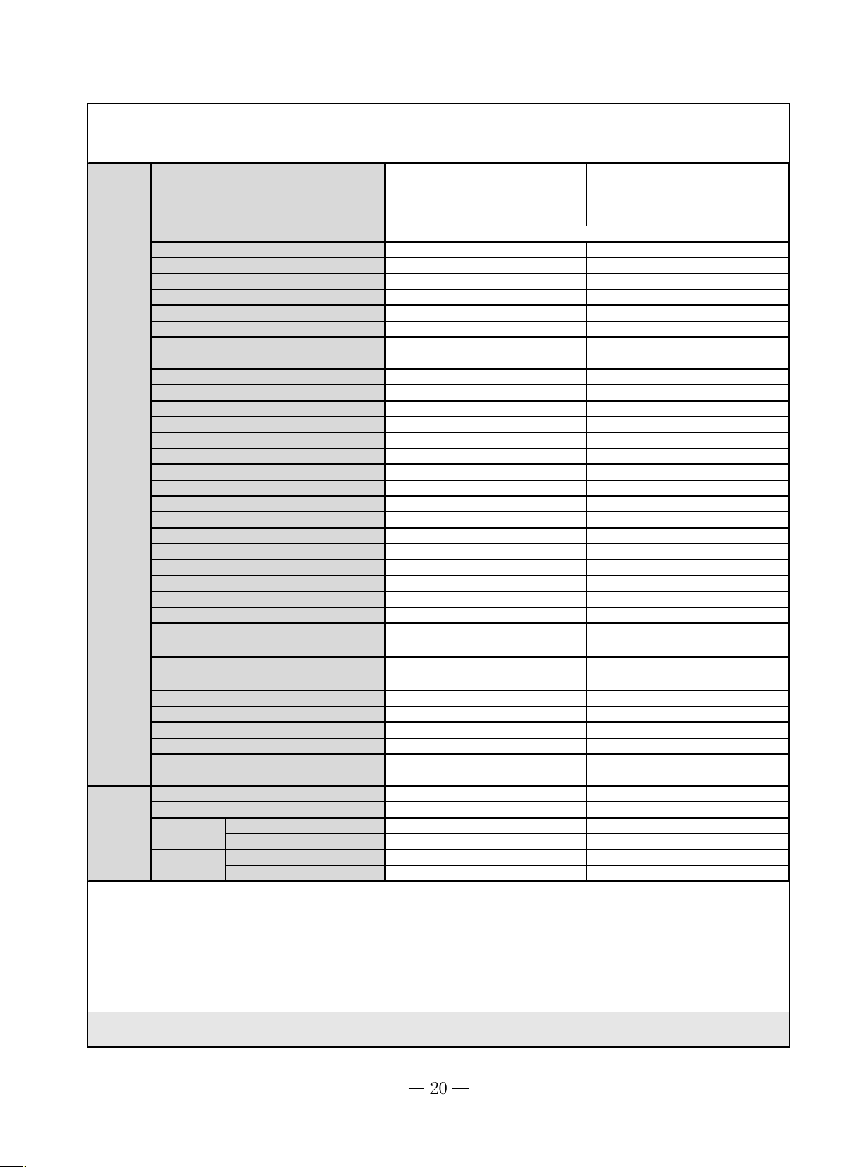
g
Model
Function
Rat ed Voltage
Rat ed F r equen cy
Total Capacity (W/Btu/h)
Power Input (W)
Rat ed I nput (W)
Rat ed Cur rent (A )
3
A ir Flow Volume (m
/h) (H/M/L)**
Dehumidifying V olume (l/ h)
EER / C.O.P (W / W )
Ener gy Class
Model of I ndo or Uni t
Fan Motor Speed ( r /min) ( H/M/L)
Output of Fan Motor (w)
Input of Heater (w)
Fan Motor Capacitor (uF)
Fan Motor RLA(A)
Fan Type-Piece
Diameter- Le ngth (mm)
GWC18MB-K1NNA5A
COOLING
220-240V
50HZ
4500
1820
2470
12.01
650
/
2.61
E
GWC18MB-K1NNA5A/I
1350/1250/1100/950
20
/
1
0.254
Cross flow fan - 1
φ108 X 954
GWH18MB-K1NNA5A
COOLING HEATING
220-240V
50HZ
4500 4800
1800 1800
2350 2400
12.01 10.03
650
/
2.61
E
GWH18MB-K1NNA5A/I
1350/1250/1100/9501350/1250/1100/1
000
20
/
1
0.254
Cross flow fa n - 1
φ108 X 954
Indoor
unit
Evaporator
Pipe Diamet er (mm)
Row-F in Gap(mm)
Coil len
th (l)×height (H)×coil
width (L)
Swing Motor Model
Output of S w ing Motor (W )
Fuse (A)
Sound P r essure Level dB (A)
(H/M/L)
Sound P ower Level dB (A)
(H/M/L)***
Dimension (W/H/D) ( mm)
D im e nsio n of P a ckage (W/ H/D)(mm)
Net Weight /Gross Weight ( k g )
A l uminum fin-co pper t ube
φ7
2-1.4
645X25.4X267
MP24AA
2.4
PCB 3.15A Transformer 0.2A
50/46/42/38
60/56/52/48
845×275×180
915×255×355
10/13
Aluminum fin- c opp er tube
φ7
2-1.4
645X25.4X267
MP24AA
2.4
PCB 3 .15A Transformer 0.2 A
50/46/42/38
60/56/52/48
845×275×180
915×255×355
10/13
Outdoor
unit
Connecti
on Pipe
Model of O utdoor Unit
Compressor Manufac turer/ trademark
Compressor M odel
Compressor Type
L.R.A. (A )
Compressor RLA(A)
Compressor Power Input(W)
Overload Protector
Throttling Method
St ar ting M ethod
Wor k in g Temp Range (℃)
Condenser
Pipe Diamete r ( mm)
Rows-Fin Gap( mm)
Coil lengt h( l ) x height ( H ) x coil width(L)
Fan Motor Speed (rpm) (H/M/ L)
Out put of Fan Motor (W)
Fan M otor RLA(A )
Fan Motor Capacitor (uF)
A ir Flow Volume of Outdoor Unit(m
3
/h)
Fan Ty pe-Piece
Fan Diamet e r ( mm)
Defrosting Method
Climate Type
Isolation
Moist ure P r otection
P ermi ssible Excessive Oper ating
Pressure for t he Dischar ge Si de( MPa)
P ermi ssible Excessive Oper ating
Pressure for the Suction Side(MPa)
Sound P r essure Level dB (A) (H/ M/L)
Sound Power Level dB (A) (H/M/L)
Dimension (W/ H/D) (mm)
Dimension of Package (L/W/H)(mm)
Net Weight / Gross Weight (kg)
Refr ig er an t Charge (kg)
Length ( m)
Gas addit ion al c h ar ge(g/m)
Outer
Diameter
Max
Distance
Liquid Pipe (mm)
Gas Pipe (mm)
Height (m) 5 5
Length ( m) 10 10
GWC18MB-K1NNA3A/O GWH18MB-K1NNA3A/O
LAMDA LAMDA
QX-34F050gA QX-34F050gA
Rotory Rotory
44 44
8.4 8.4
1820 1820
Inset Inset
Capillary Capillary
Capacitor Capacitor
-7~43 -7~43
Aluminum fin- c o pper tube Aluminum fin-copper tube
77
2-1.4 2-1.6
782X495X25.4 782X495X25.4
850±20 860±20
30W 35W
0.35 0.37
22.5
//
Axial fan -1 A xial fan -1
¢
400
¢
400
A u t o defrost Auto def r ost
T1 T1
II
IP24 IP24
2.5 2.5
0.6 0.6
57 57
67 67
848×540×320 848×540×320
878×360×580 878×360×580
41/46 43/48
R22/1.0 R22/1.04
55
30 30
Φ6(1/4") Φ6(1/4")
Φ12(1/2") Φ12(1/2")
The above data is subject to change without notice. Please refer to the nameplate of the unit.
g
Model
Function
Rat ed Voltage
Rat ed F r equen cy
Total Capacity (W/Btu/h)
Power Input (W)
Rated Input (W)
Rated Current (A)
Air Flow Volume (m
3
/h) (H/M/L)**
Dehumidifying V olume (l/ h)
EER / C.O.P (W / W )
Ener gy Class
Model of Indoor Unit
GWC18 MC-K1NNA*A
COOLING
220-240V~
50Hz
5300
1900
2700
10.9
850/780/650/550
3
2.78
C
GWC18MC-K1NNA*A/I
GWH 18MC-K1NNA*A
COOLING HEA TING
220-240V~
50Hz
5300 5700
1900 1800
2700 2600
10.9 10.4
850/780/650/550
3
2.78
C
GWH18MC-K1NNA*A/I
Indoor
unit
Fan Motor S peed ( r / min) (H / M/L)
Output of Fan Motor (w)
Inpu t of Heat er (w)
Fan Motor Capac itor (uF)
Fan Motor RLA(A)
Fan Type- P iec e
Diameter-Length (mm)
Evaporator
Pipe Diameter ( mm)
Row-F in Gap(mm)
Coil len
th (l)×height (H)×coil
width (L)
Swing Motor Model
Output of S w ing Motor (W )
Fuse (A)
Sound P r e ssure Level dB (A)
(H/M/L)
Sound P owe r Le vel dB (A)
(H/M/L)***
Dimension (W/H/D) ( mm)
Dimension of Package(W/H/D)(mm)
Net Weight /Gross Weight ( k g)
1350/1200/1050/900
20
/
1
0.25
Cross flow f an - 1
φ98 X 710
Aluminum fin- c opp er tube
Φ7
2-1.4
715X304.8X25.4
MP28VB
2.5
PCB 3 .15A Transformer 0.2 A
47/44/41/37
57/54/51/47
940X200X298
1020X285X380
13/18
1350/1200/1050/900
20
/
1
0.25
Cross flow fa n - 1
φ98 X 710
Aluminum fin- c opp er tube
Φ7
2-1.4
715X304.8X25.4
MP28VB
2.5
PCB 3.15A Transformer 0.2 A
47/44/41/37
57/54/51/47
940X200X298
1020X285X380
13/18
Outdoor
(
/h)
unit
Connecti
on Pipe
Model of Outdoor Unit
Compressor Manufacturer/trademark
Compressor Model
Compressor Type
L. R.A. (A)
Compressor RLA(A)
Compressor Power Input(W)
Overload P rotector
Throttling Method
Starting Method
Working Temp Range (℃)
Condenser
Pipe Diameter (mm)
Rows-F i n Gap(mm)
Coil length(l) x height (H) x coil width(L)
Fan Motor Speed (rpm) (H/M/L)
Output of Fan Motor (W)
Fan Motor RLA(A)
Fan Motor Capacitor ( uF)
3
Air Flow Volume of Outdoor Unit
m
Fan Type-Piece
Fan Diameter (mm)
Defrosti ng Method
Climate Type
Isolation
Moisture Protection
er
mi ssible Excessive Operat ing
P
Pressure for the Discharge Side(MPa)
Permissible Excessiv e Operati ng
Pressure for the Suction Side(M Pa)
Sound Pressure Level dB (A) (H/M/L)
Sound Power Level dB (A ) (H/M /L)
Dimension (W/H/D) (mm)
Dimension of Package ( L/W/ H)(mm)
Net Weight /Gross Weight (kg)
Refrigerant Charge ( kg)
Length (m)
Gas additional charge(g/m)
Outer
Diameter
Max
Distance
Liquid P ipe (mm) Φ6 Φ6
Gas Pipe (mm) Φ12 Φ12
Height (m) 5 5
Length (m) 10 10
GWC18MC-K1NNA1A/O
GWC18MC-K1NNA2A/O
GWC18MC-K1NNA3A/O
GWC18MC-K1NNA4A/O
GWH18MC-K1NNA1A/O
GWH18MC-K1NNA2A/O
GWH18MC-K1NNA3A/O
GWH18MC-K1NNA4A/O
MELANDA REF RIGERATION CO., LTD
QX-34F050gA QX-34F050gA
rotary compressor rotary compressor
44 44
8.4 8.4
1820 1820
Built-in Built-in
Capillary Capillary
Capacitor Capacitor
-7℃≤T≤43
℃
-7℃≤T≤43
℃
A l uminum fi n- c opper tube Aluminum f in-copper tube
Φ7 Φ9.52
2-1.4 1-1.6
815.7×495.3×25.4 806×660×22
900 860
48 48
0.4 0.62
2.5 3.5
2000 2790
Ax ial fan -1 Axial fan -1
Φ400 Φ473
Auto defrost Auto defrost
T1 T1
II
IP24 IP24
2.5 2.5
0.6 0.6
56 56
66 66
848X320X540 913X378X680
878X360X580 994X428X725
45/50 46/50
R22/1.2 R22/1.3
44
50 50
The above data is subject to change without notice. Please refer to the nameplate of the unit.
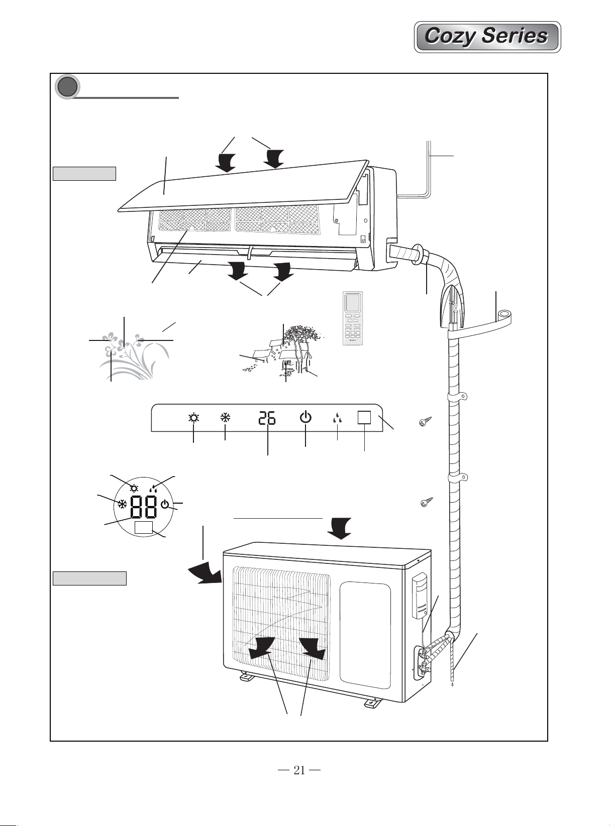
Part name
3
Part name
Air in
Indoor unit
Cooling
Remote
control window
Heat
Cool
Heat
Heat
Front Panel
Guide louver
Filter
Indicator light
Power
Power/Run
Cooling
Heat
DRY
Heat
Air out
Cooling
Cool
Power
Heat
Power/Run
Set Temp
Wireless remote control
Indicator light
Run
DRY
Remote control window
Power cable
Wrapping Tape
Wall Pipe
LED displayer
Cooling
Set Temp
Remote control window
Outdoor unit
LED displayer
Run
Air in
Connection pipe
Drainage hose
Air out
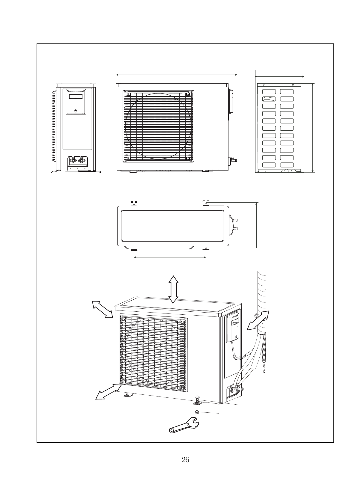
Outline and installation dimension
4
Outline and installation dimension
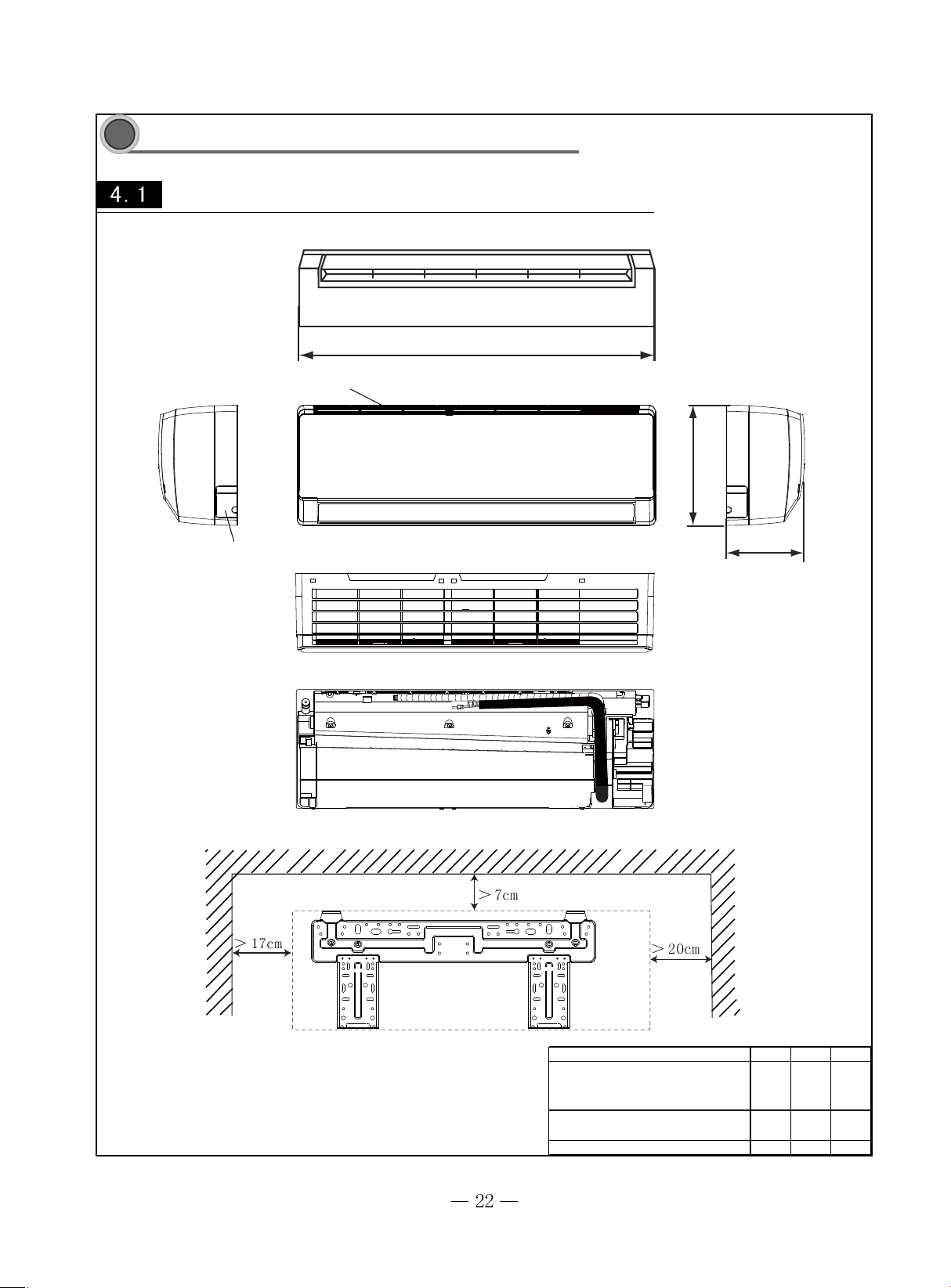
Outline and installation dimensions of indoor unit
W
Air inlet
H
Left
Tube exit
D
Rear View
Ceiling
Right
Wall-Mounting Plate
MODEL W(㎜)H(㎜)D(㎜)
GWC05MA-K1NNA9A/I
GWC07MA-K1NNA9A/I
09K
12K/18K(MB) 845 275 180
18K(MC) 940 298 200
790 265 170
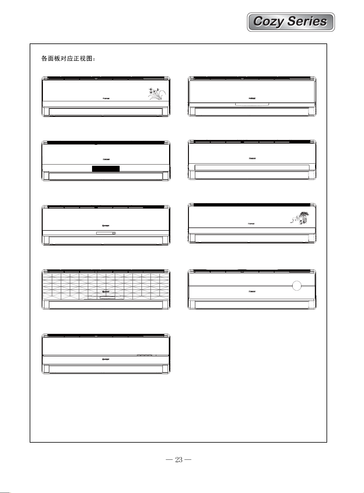
A1 Panel
A2 Panel
A4 PanelA3 Panel
A5 Panel
A7 Panel
A9 Panel
CoolHeat Power
A6 Panel
Cool
Power
Heat
A8 Panel
Dry
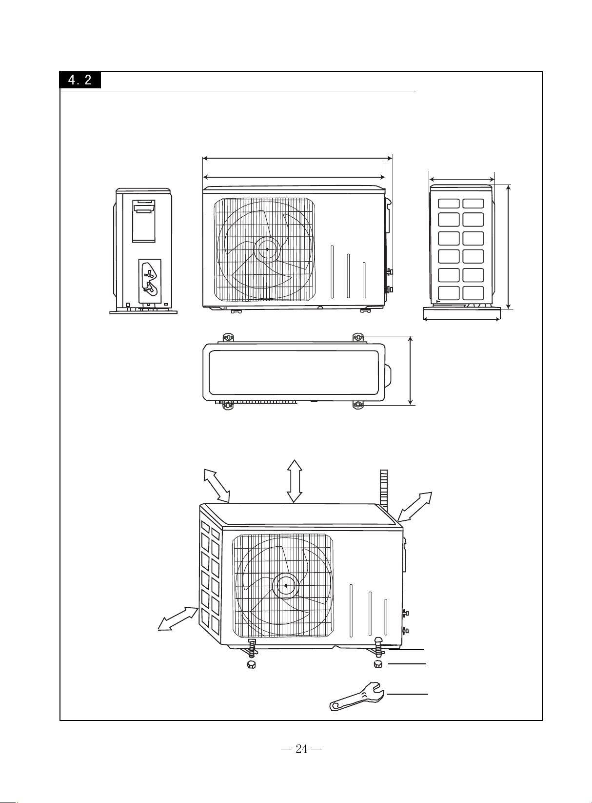
Outline and installation dimensions of outdoor unit
GWC05MA-K1NNA9A/O and 09K(Besides GWC09MA-K1NNA9A/O ) Outdoor unit
720
660
260
430
320
286
Unit:mm
Over 60cm
Over 60cm
Over 60cm
Over 60cm
Bolt
Nut
Wrench
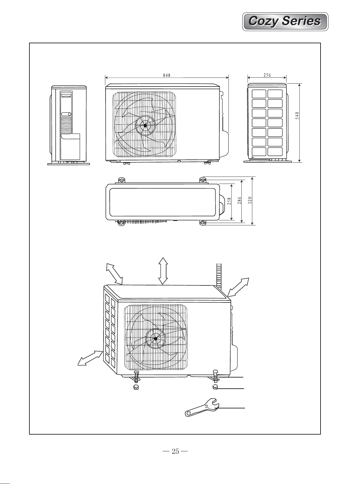
GWC07MA-K1NNA9A/O GWC09MA-K1NNA9A/O, 12K Outdoor unit ,18K(MB)and 18K(MC) Cool
only Outdoor unit
Over 30cm
Unit:mm
Over 30cm
Over 60cm
Over 60cm
Bolt
Nut
Wrench
18K(MC) Cool and Heat Outdoor unit
913
378
680
342
Over 30cm
Over 30cm
550
Unit:mm
Over 60cm
Over 60cm
Bolt
Nut
Wrench
55
5
55
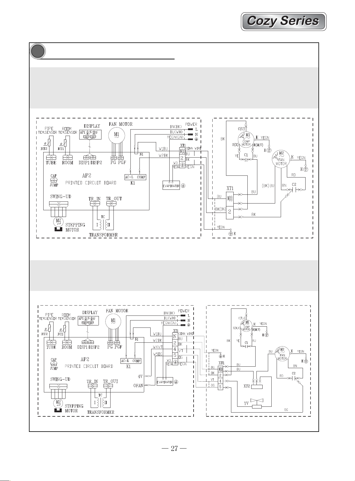
Electrical circuit diagram
Electrical circuit diagram
GWC09MA-K1NNA2A GWC12MB-K1NNA2A GWC09MA-K1NNA3A GWC12MB-K1NNA3A
GWC09MA-K1NNA4A GWC12MB-K1NNA4A GWC09MA-K1NNA5A GWC12MB-K1NNA5A
GWC12MB-K1NNA3B GWC12MB-K1NNA7A GWC12MB-K1NNA7B GWC09MA-K1NNA8A
GWC12MB-K1NNA8A GWC12MB-K1NNA8B GWC18MB-K1NNA4A GWC18MB-K1NNA5A
OUTDOOR UNIT
INDOOR UNIT
GWH09MA-K1NNA2A GWH12MB-K1NNA2A GWH09MA-K1NNA3A GWH12MB-K1NNA3A
GWH09MA-K1NNA4A GWH12MB-K1NNA4A GWH09MA-K1NNA5A GWH12MB-K1NNA5A
GWH09MA-K1NNA8A GWH18MB-K1NNA4A GWH18MB-K1NNA5A
OUTDOOR UNIT
INDOOR UNIT
GWC05MA-K1NNA9A GWC07MA-K1NNA9A GWC09MA-K1NNA9A GWC09MA-K1NNA3B
PIPE
TEM.SENSOR
0
RT2
TUBE
CAP
JUMP
ROOM
TEM.SENSOR
0
RT1
ROOM
DISPLAY
AP1
DISP1
PRINTED CIRCUIT BOARD
SWING-UD
M2
STEPPING
MOTOR
GWC09MA-K1NNA1B
DISP2
AP2
TR_IN
TC
I I
TRANSFORMER
FAN MOTOR
M1
PG
PGF
TR_OUT
I
AC-L
K1
N1
COMP
POWER
BN(BK)
BU(WH)
YEGN(GN)
W1BU
W2BK
W3
YEGN
EVAPORATOR
INDOOR UNIT
XT1
N(1)
2
L
N
CONN WIRE
BU
BK
YEGN
BK
BU
(BN)
YEGN
SAT
1
2
C(U)
S(X)
M1
COMP
MOTOR
C1
YE
BK
XT1
OUTDOOR UNIT
E
YEGN
E
(BK)
MOTOR
BU
R(M,V)
BU
BU
FAN
M2
E
YEGN
E
RD
C2
BN
N(1)
2
BK
E
PIPE
TEM.SENSOR
0
RT2
TUBE
CAP
JUMP
SWING-UD
ROOM
TEM.SENSOR
0
RT1
ROOM
DISPLAY
AP1
DISP1
PRINTED CIRCUIT BOARD
M2
STEPPING
MOTOR
FAN MOTOR
M1
PG
AP2
TR_IN
TC
I I
TRANSFORMER
PGF
AC-L
TR_OUT
I
K1
N1
COMP
BN(BK)
POWER
BU(WH)
YEGN(GN)
XT1
W1BU
N(1)
W2BK
2
W3
YEGN
EVAPORATOR
INDOOR UNIT
L
N
CONN WIRE
BU
BK
YEGN
BK
BU
(BN)
YEGN
SAT
1
2
C(U)
S(X)
M1
COMP
MOTOR
C1
YE
BK
XT1
OUTDOOR UNIT
E
YEGN
R(M,V)
E
BU
(BK)
BU
BU
M2
FAN
MOTOR
BN
E
RD
YEGN
E
C2
N(1)
2
BK
E
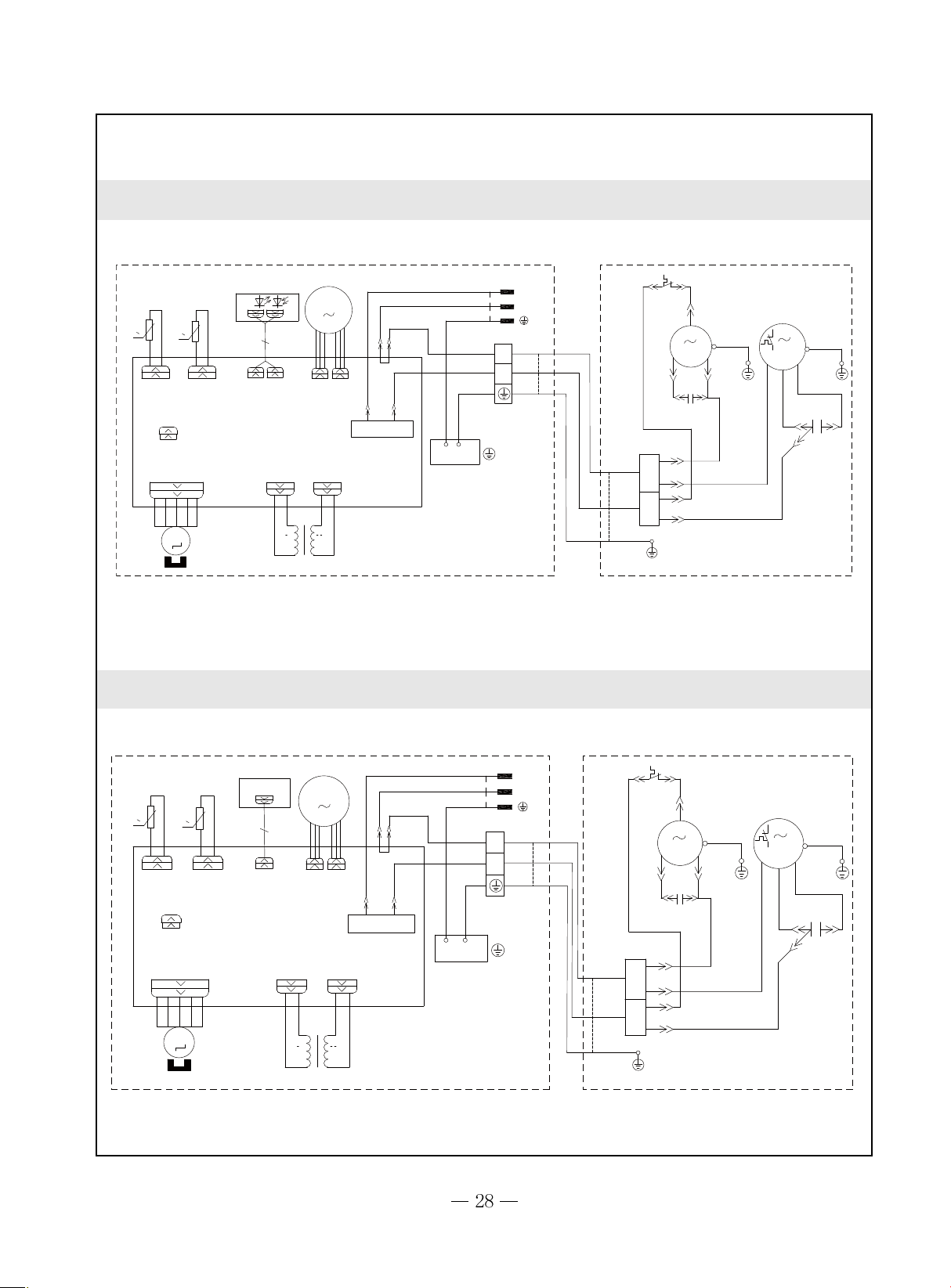
GWH12MB-K1NNA8A
TUBE
TEM.SENSOR
0
RT2
TUBE
CAP
JUMP
SWING_UD
M2
ROOM
TEM.SENSOR
0
RT1
ROOM
DISPLAY
DISP1
AP2
PRINTED CIRCUIT BOARD
TR_IN
STEPPING
MOTOR
II
TRANSFORMER
AP1
DISP2
TR_OUT
TC
I
FAN MOTOR
M1
PG
PGF
AC-L
HEALTH-L HEALTH-N
RD BU
N1
VT
COMP
K1
4V
OFAN
IONIZER
INDOOR UNIT
BN
BU
YEGN
BU
BK
OG
YEGN
EVAPORATOR
POWER
XT1
CONN WIRE
N
BU
2
BK
4
VT
5
OG
YEGN
PE
L
N
N
C
1
2
XT
E
GWC09MA-K1NNA1A GWC12MB-K1NNA1A GWC12MB-K1NNA1B
BL
VT
OR
FAN
MOTOR
YE/GN
XT
C
BN(OR)
M2
~
YV
4-WAY VALVE
BL
C
BK(BL)
RD
S
BK
E
E
SAT
OUTDOOR UNIT
BL
YE
R<M>
COMPRESSOR
M1
~
E
YE/GN
C
E
BK
INDOOR UNIT
OUTDOOR UNIT
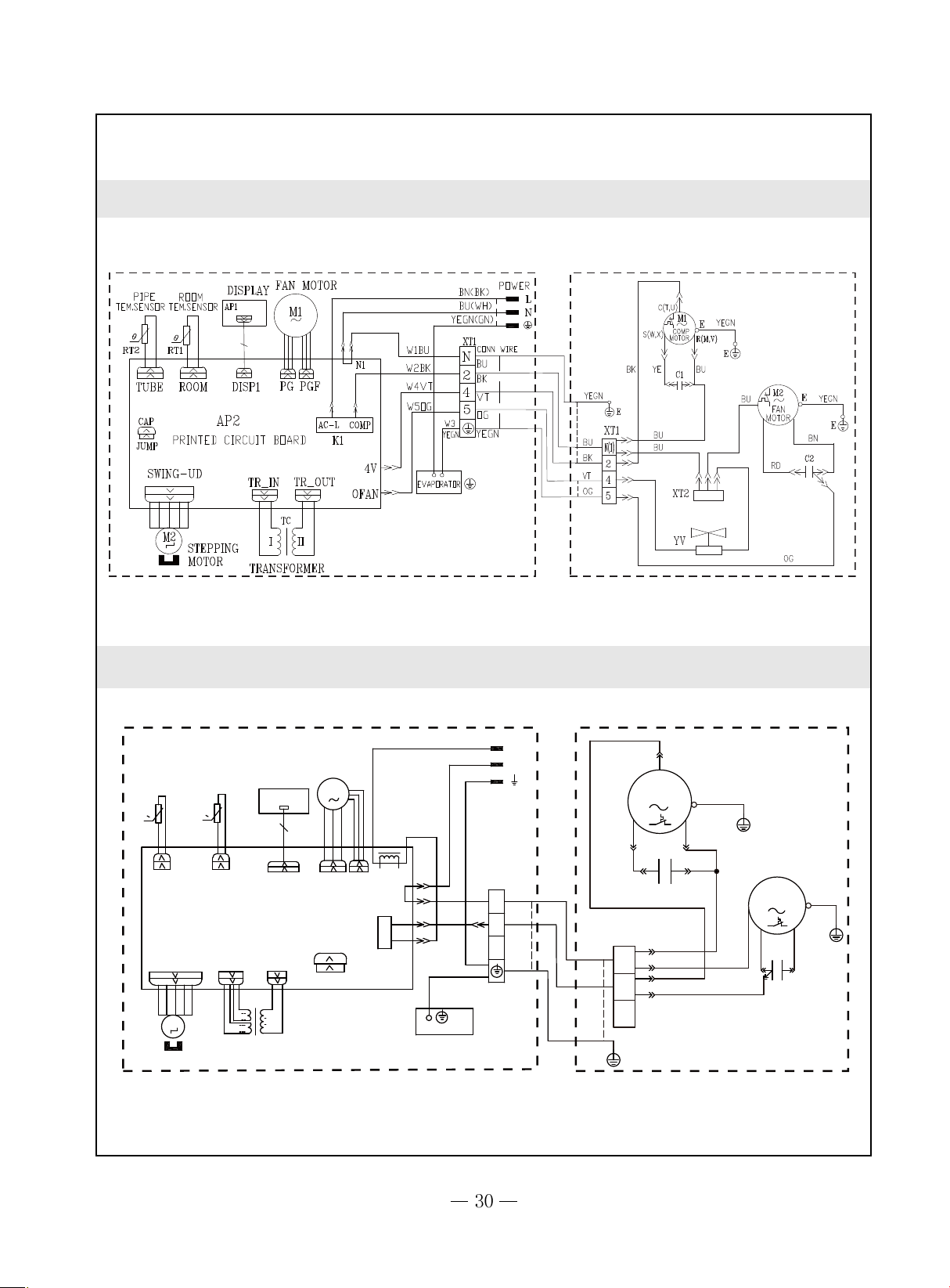
GWH09MA-K1NNA1A GWH12MB-K1NNA1A
OUTDOOR UNIT
INDOOR UNIT
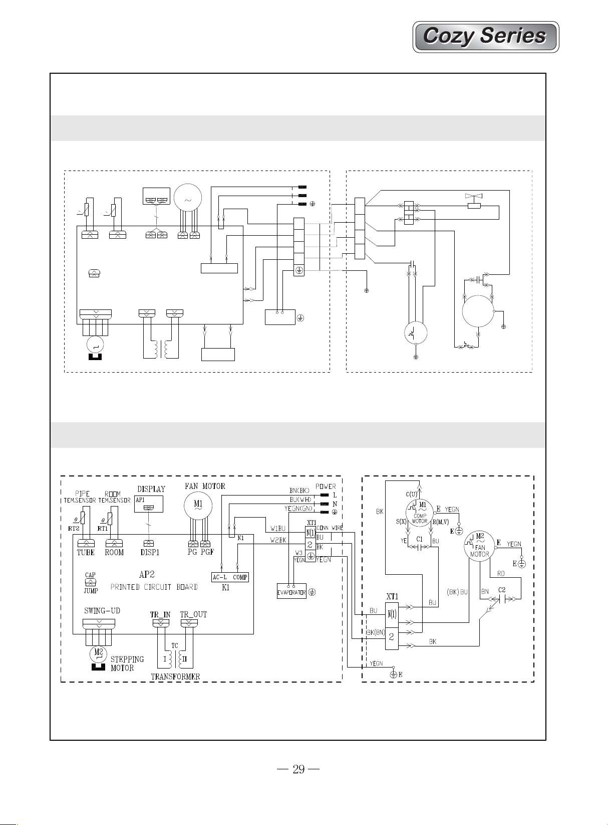
GWC18MC-K1NNA1A GWC18MC-K1NNA6A GWC18MC-K1NNA9A
BN
L
0
TUBE
RECEIVER AND
DISPLAY BOARD
AP1
DISPLAY
DISP1
ROOM TEMP.
SENSOR
0
RT2
ROOM
TUBE TEMP.
SENSOR
RT1
AP1 PRINTED CIRCUIT BOARD
SWING
M2
STEPPING MOTOR
TR-OUT
TR-IN
TC
I
I
I
III
TRANSFORMER
FAN MOTOR
M1
PG
PGF
CAP
JUMP
K1
L101
N1
4
3
BU
YEGN
BU
BK
YEGN
PE
EVAPORATOR
INDOOR UNIT
N
POWER
XT
BU
N(1)
BK
2
3
YEGN
BU
BK
YEGN
C(T,U)
S(W,X)
4YE
XT1
N(1)
2
3
PE
5BK
COMP
C1
2BU
OUTDOOR UNIT
COMP.
PE
6YEGN
PE
R(M,V)
3BU
1BU
J
BK
(BU)
7BK
FAN MOTOR
PE
M
BN
RD
C2
YEGN
PE
 Loading...