

Gree GWC36LB-D3DNA5G, GWC30LB-D3DNA3G, GWH30LB-D3DNA5G, GWH30LB-D3DNA3G, GWH36LB-D3DNA3G Service Manual
...
GREE ELECTRIC APPLIANCES,INC.OF ZHUHAI
Change for Life
Service Manual
Model: GWC30LB-D3DNA3G
GWC30LB-D3DNA3H
GWH30LB-D3DNA3G
GWC36LB-D3DNA3G
GWC30LB-D3DNA5G
GWH30LB-D3DNA5G
GWH36LB-D3DNA3G
GWC36LB-D3DNA5G
GWH36LB-D3DNA5G
GWC30LB-D3DNB2G
GWH30LB-D3DNB2G
GWC36LB-D3DNB2G
GWH36LB-D3DNB2G
(Refrigerant R410A)

Table of Contents
Service Manual
Part
1. Summary
2. Specications
2.1 Specication Sheet ...........................................................................................................2
2.2 Operation Characteristic Curve ........................................................................................8
2.3 Capacity Variation Ratio According to Temperature .........................................................8
2.4 Noise Curve ......................................................................................................................9
2.5 Cooling and Heating Data Sheet in Rated Frequency .....................................................9
: Technical Information
Ⅰ
......................................................................................................................1
..........................................................................................................2
3. Outline Dimension Diagram
3.1 Indoor Unit ......................................................................................................................10
3.2 Outdoor Unit ...................................................................................................................10
4. Refrigerant System Diagram
5. Electrical Part
5.1 Wiring Diagram ...............................................................................................................13
5.2 PCB Printed Diagram .....................................................................................................15
.........................................................................................................13
.......................................................................1
......................................................................10
.................................................................... 11
6. Function and Control
6.1 Remote Controller Introduction .....................................................................................17
6.2 Brief Description of Modes and Functions ......................................................................21
Part
: Installation and Maintenance
Ⅱ
7. Notes for Installation and Maintenance
8. Installation
8.1 Installation Dimension Diagram ......................................................................................26
8.2 Installation Parts-checking ............................................................................................28
8.3 Selection of Installation Location ....................................................................................28
8.4 Electric Connection Requirement ..................................................................................28
8.5 Installation of Indoor Unit ................................................................................................28
8.6 Installation of Outdoor Unit .............................................................................................31
8.7 Vacuum Pumping and Leak Detection ...........................................................................32
8.8 Check after Installation and Test Operation ...................................................................32
................................................................................................................26
......................................................................................17
.................................................24
..........................................24
8.9 Wired Controller .............................................................................................................33
Table of contents

Service Manual
9. Troubleshooting
9.1 Flashing LED of Indoor/Outdoor Unit and Primary Judgement ......................................43
9.2 How to Check Simply the Main Part ...............................................................................52
9.3 Troubleshooting for Normal Malfunction .........................................................................68
10. Exploded View and Parts List
10.1 Indoor Unit ....................................................................................................................70
10.2 Outdoor Unit .................................................................................................................76
11. Removal Procedure
11.1 Removal Procedure of Indoor Unit ...............................................................................80
11.2 Removal Procedure of Outdoor Unit ............................................................................89
Appendix:
Appendix 1: Reference Sheet of Celsius and Fahrenheit ....................................................95
Appendix 2: Conguration of Connection Pipe .....................................................................95
Appendix 3: Pipe Expanding Method ...................................................................................96
........................................................................................................................95
..................................................................................................43
..............................................................70
.......................................................................................81
Appendix 4: List of Resistance for Temperature Sensor ......................................................97
Service Manual
Part
: Technical Information
Ⅰ
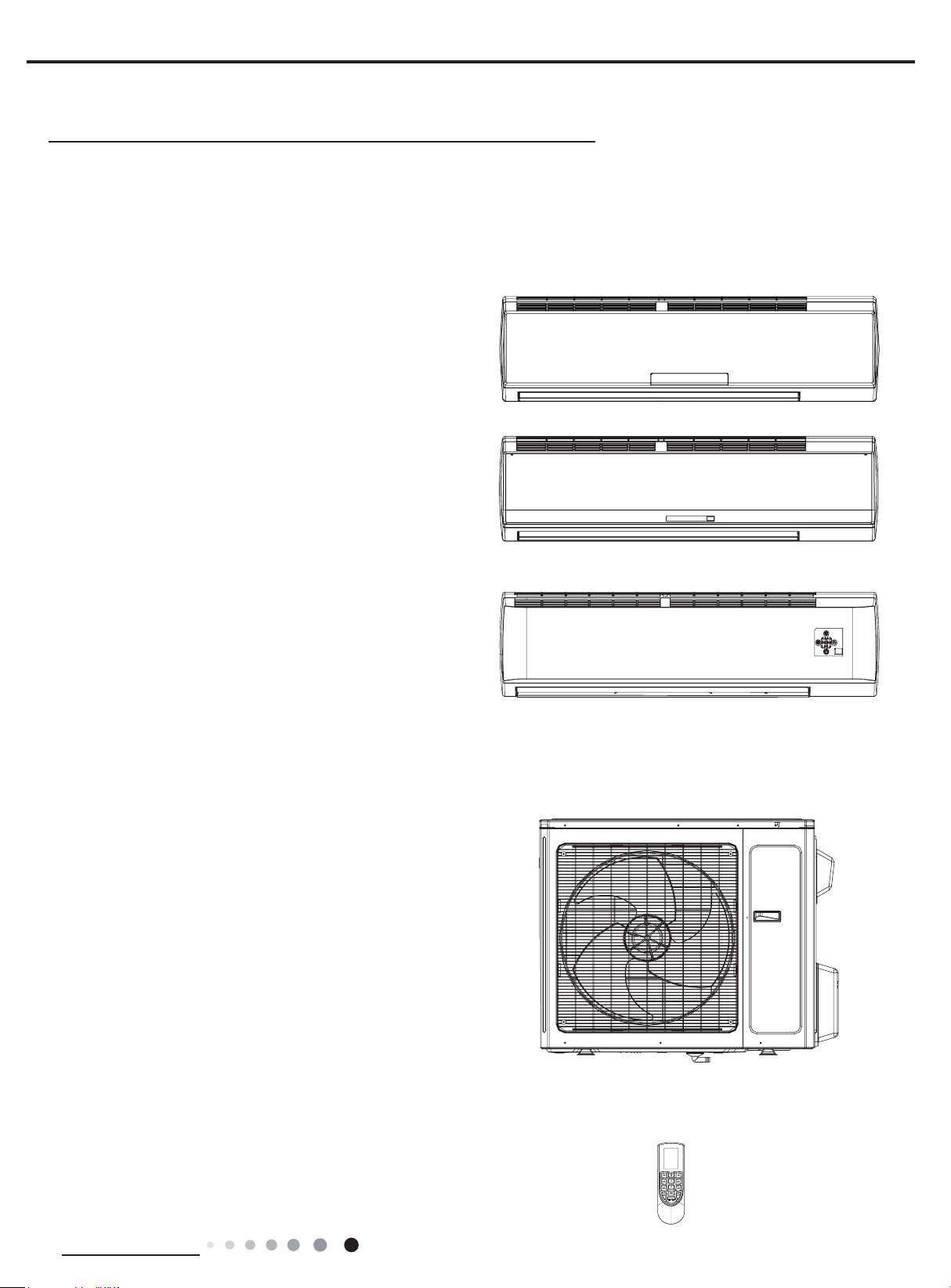
1. Summary
Indoor Unit:
GWC30LB-D3DNA3G/I
GWC30LB-D3DNA3H/I
GWH30LB-D3DNA3G/I
GWC36LB-D3DNA3G/I
GWH36LB-D3DNA3G/I
GWH30LB-D3DNA5G/I
GWC36LB-D3DNA5G/I
GWH36LB-D3DNA5G/I
GWC30LB-D3DNB2G/I
GWH30LB-D3DNB2G/I
GWC36LB-D3DNB2G/I
GWH36LB-D3DNB2G/I
Outdoor Unit:
GWC30LB-D3DNA3G/O
GWC30LB-D3DNA3H/O
GWH30LB-D3DNA3G/O
GWC36LB-D3DNA3G/O
GWH36LB-D3DNA3G/O
Remote Controller:
YAN1F1F
Technical Information
1
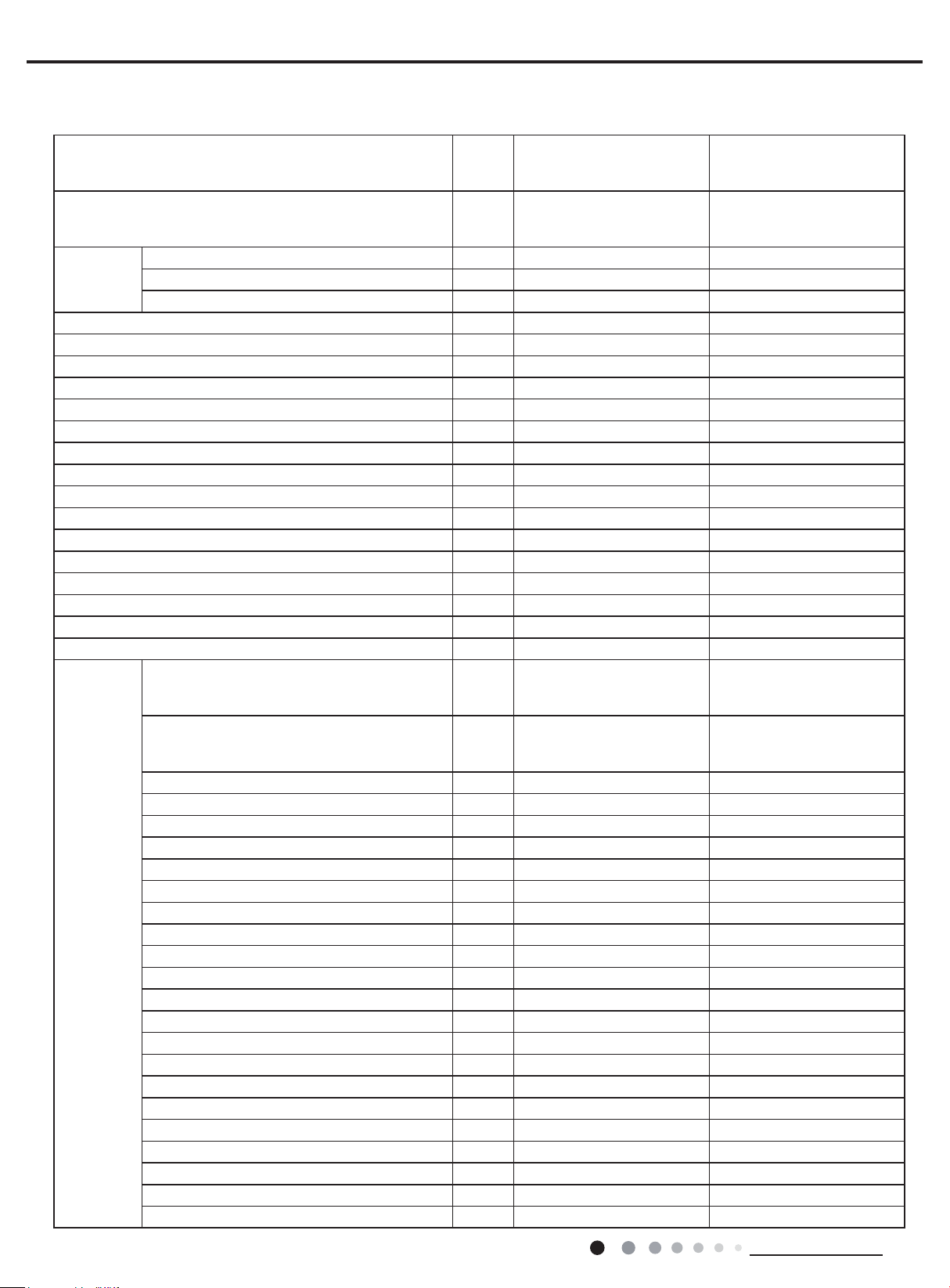
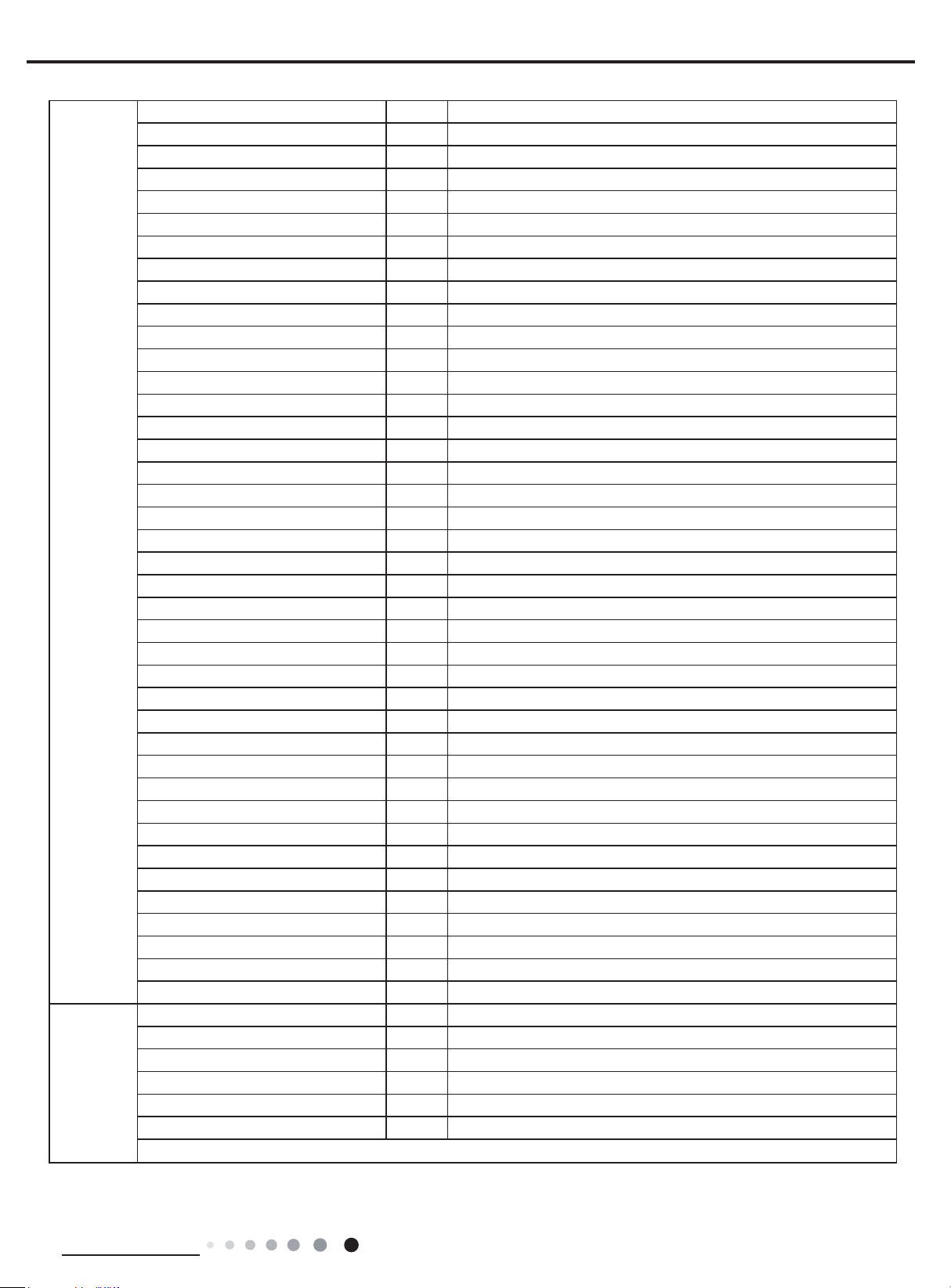
2. Specications
2.1 Specication Sheet
GWC30LB-D3DNA3G
Model
Product Code
Rated Voltage V~ 208/230 208/230
Power Supply
Power Supply Mode Outdoor Outdoor
Cooling Capacity(Min~Max) Btu/h 28000(9485~30026) 28000(9485~30026)
Heating Capacity(Min~Max) Btu/h / 28400(9997~32994)
Cooling Power Input(Min~Max) W 2700(350~3900) 2700(350~3900)
Heating Power Input(Min~Max) W / 2800(450~4000)
Cooling Power Current A 11.5 11.5
Heating Power Current A / 12
Rated Input W 3900 4000
Rated Current A 17 17.5
Air Flow Volume(SH/H/M/L) CFM 706/618/530/412 706/618/530/412
Dehumidifying Volume Pint/h 6.34 6.34
EER (Btu/h)/W 10.37 10.36
COP (Btu/h)/W / 10.14
SEER 18 18
SCOP / 9
Application Area yd
Indoor Unit
Rated Frequency Hz 60 60
Phases 1 1
2
Model of indoor unit
Indoor Unit Product Code
Fan Type Cross-ow Cross-ow
Diameter Length(DXL) inch Φ4 1/4X20 9/16X2 Φ4 1/4X20 9/16X2
Fan Motor Cooling Speed (SH/H/M/L) r/min 1350/1150/950/850 1350/1150/950/850
Fan Motor Heating Speed (SH/H/M/L) r/min / 1350/1200/1000/800
Output of Fan Motor W 70 70
Fan Motor RLA A 0.4 0.4
Fan Motor Capacitor μF / /
Evaporator Form Aluminum Fin-copper Tube Aluminum Fin-copper Tube
Pipe Diameter inch Φ9/32 Φ9/32
Row-n Gap inch 2-1/16 2-1/16
Coil Length (LXDXW) inch 42 9/32X1X15X2 42 9/32X1X15X2
Swing Motor Model MP24BA MP24BA
Output of Swing Motor W 2 2
Fuse A 3.15 3.15
Sound Pressure Level (SH/H/M/L) dB (A) 51/45/41/37 51/45/41/37
Sound Power Level (SH/H/M/L) dB (A) 61/55/51/47 61/55/51/47
Dimension (WXHXD) inch 53 9/64X12 53/64X10 53 9/64X12 53/64X10
Dimension of Carton Box (LXWXH) inch 56 19/32X16 1/2X13 1/2 56 19/32X16 1/2X13 1/2
Dimension of Package (LXWXH) inch 56 3/4X16 9/16X14 56 3/4X16 9/16X14
Net Weight Ib 41.9 41.9
Gross Weight Ib 51.8 51.8
GWC30LB-D3DNA5G
GWC30LB-D3DNB2G
CB171010700
CB169001200
CB433000100
41.86-62.19 41.86-62.19
GWC30LB-D3DNA3G/I
GWC30LB-D3DNA5G/I
GWC30LB-D3DNB2G/I
CB171N10700
CB169N01200
CB433N00100
GWH30LB-D3DNA3G
GWH30LB-D3DNA5G
GWH30LB-D3DNB2G
CB171010600
CB169001100
CB433000200
GWH30LB-D3DNA3G/I
GWH30LB-D3DNA5G/I
GWH30LB-D3DNB2G/I
CB171N10600
CB169N01100
CB433N00200
Service Manual
2
Technical Information
Service Manual
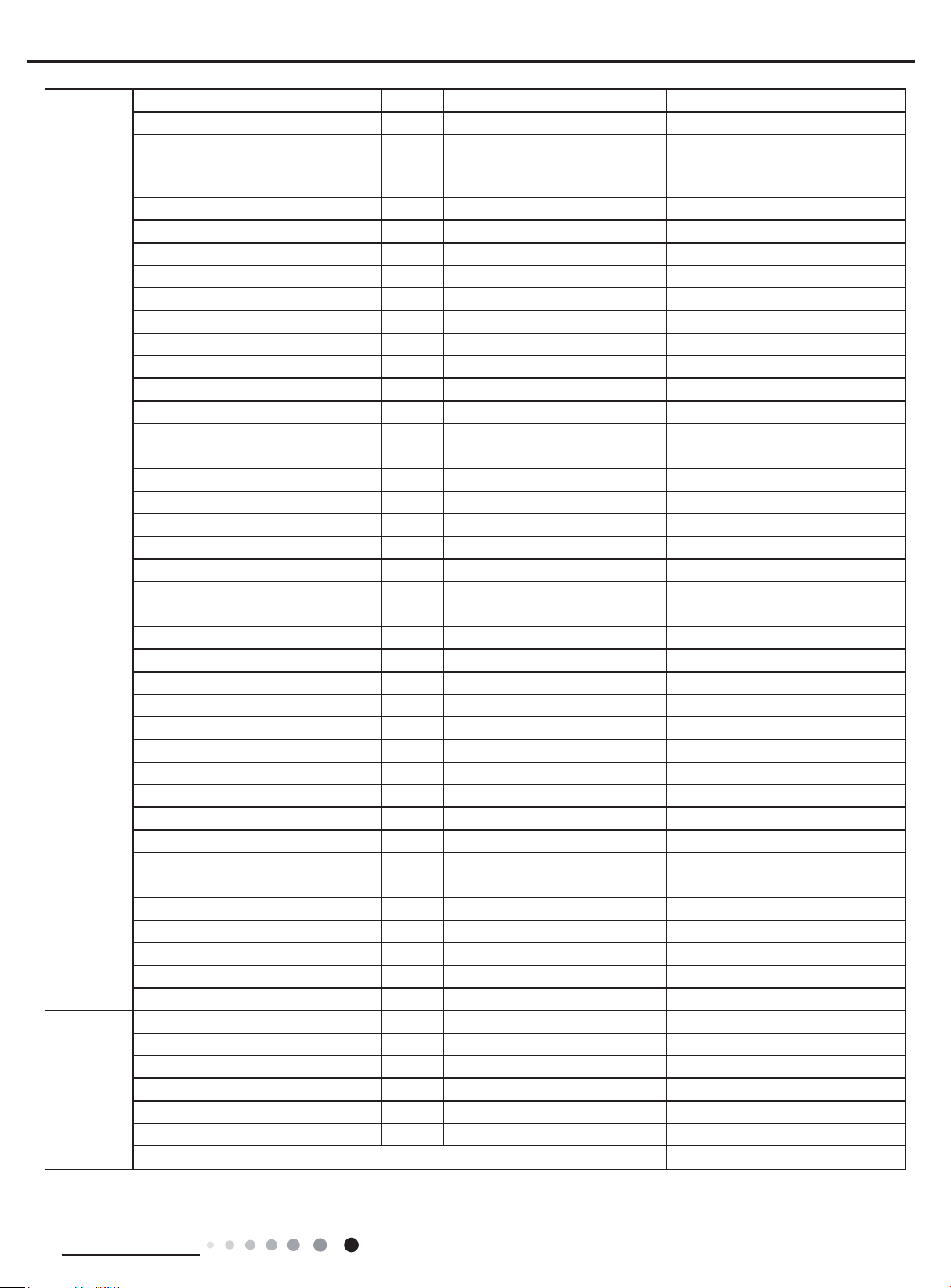
Outdoor Unit
Connection
Pipe
Model of Outdoor Unit GWC30LB-D3DNA3G/O GWH30LB-D3DNA3G/O
Outdoor Unit Product Code CB171W10700 CB171W10600
Compressor Manufacturer/Trademark
Compressor Model QXAS-D23zX090 QXAS-D23zX090
Compressor Oil RB68EP RB68EP
Compressor Type Rotary Rotary
Compressor Locked Rotor Amp (L.R.A) 40 40
Compressor RLA A 13.45 13.45
Compressor Power Input W 2450 2450
Overload Protector 1NT11L-6233 1NT11L-6233
Throttling Method Electron expansion valve+Capillary Electron expansion valve+Capillary
Operation temp ºF 61~86 61~86
Ambient temp (cooling) ºF 5~115 5~115
Ambient temp (heating) ºF / -4~75
Condenser Form Aluminum Fin-copper Tube Aluminum Fin-copper Tube
Pipe Diameter inch Φ5/16 Φ5/16
Rows-n Gap
Coil Length (LXDXW) inch 37 1/2X1 1/2X29 7/16 37 1/2X1 1/2X29 7/16
Fan Motor Speed rpm 795 795
Output of Fan Motor W 120 120
Fan Motor RLA A 0.45 0.45
Fan Motor Capacitor μF / /
Air Flow Volume of Outdoor Unit CFM 2354 2354
Fan Type Axial-ow Axial-ow
Fan Diameter inch Φ21 21/32 Φ21 21/32
Defrosting Method / Automatic Defrosting
Climate Type T1 T1
Isolation I I
Moisture Protection IP24 IP24
Design Pressure(High) PSIG 550 550
Design Pressure(Low) PSIG 240 240
Sound Pressure Level (H/M/L) dB (A) 62/-/- 62/-/-
Sound Power Level (H/M/L) dB (A) 72/-/- 72/-/-
Dimension (WXHXD) inch 39 1/2X31 7/64X16 13/16 39 1/2X31 7/64X16 13/16
Dimension of Carton Box (LXWXH) inch 42 1/2X19X33 42 1/2X19X33
Dimension of Package (LXWXH) inch 42 21/32X19 13/64X33 21/32 42 21/32X19 13/64X33 21/32
Net Weight Ib 152.1 154.4
Gross Weight Ib 163.2 165.4
Refrigerant R410A R410A
Refrigerant Charge oz 84.66 84.66
Length ft 24 39/64 24 39/64
Gas Additional Charge oz/ft 0.2 0.5
Outer Diameter Liquid Pipe inch Φ1/4 Φ1/4
Outer Diameter Gas Pipe inch Φ5/8 Φ5/8
Max Distance Height ft 32 3/16 32 3/16
Max Distance Length ft 98 27/64 98 27/64
Note:The connection pipe applies metric diameter.
inch
ZHUHAI LANDA COMPERSSOR
CO.LTD.
2-1/16 2-1/16
ZHUHAI LANDA COMPERSSOR
CO.LTD.
The above data is subject to change without notice; please refer to the nameplate of the unit.
Technical Information
3
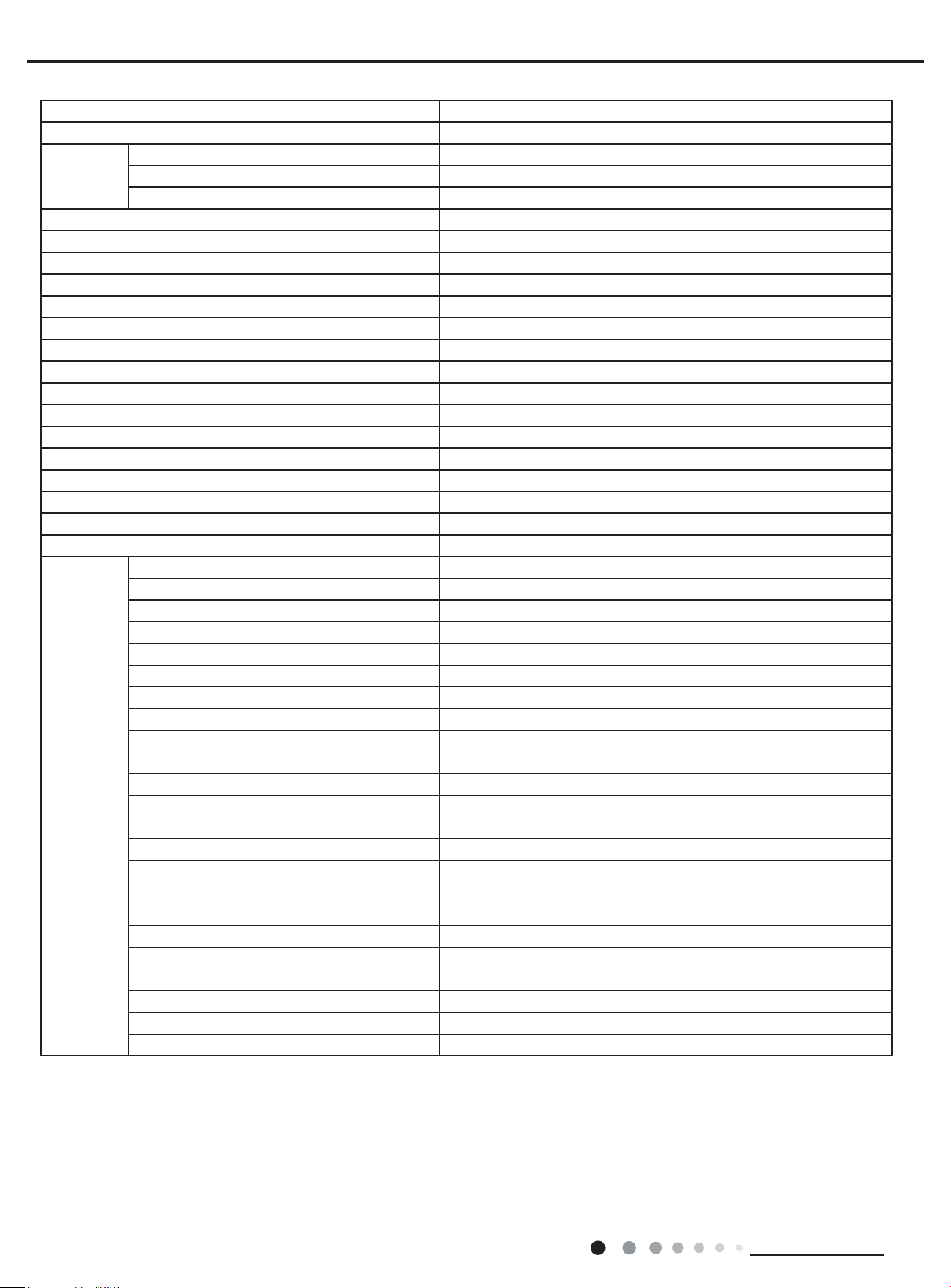
Model GWC30LB-D3DNA3H
Product Code CB171011800
Rated Voltage V~ 208/230
Power Supply
Rated Frequency Hz 60
Phases 1
Power Supply Mode Outdoor
Cooling Capacity(Min~Max) Btu/h 28000(9485~30026)
Heating Capacity(Min~Max) Btu/h /
Cooling Power Input(Min~Max) W 2700(350~3900)
Heating Power Input(Min~Max) W /
Cooling Power Current A 11.5
Heating Power Current A /
Rated Input W 3900
Rated Current A 17
Air Flow Volume(SH/H/M/L) CFM 706/618/530/412
Dehumidifying Volume Pint/h 6.34
EER (Btu/h)/W 10.37
COP (Btu/h)/W /
SEER 18
SCOP /
Application Area yd
2
41.86-62.19
Model of indoor unit GWC30LB-D3DNA3H/I
Indoor Unit Product Code CB171N11800
Fan Type Cross-ow
Diameter Length(DXL) inch Φ4 1/4X20 9/16X2
Fan Motor Cooling Speed (SH/H/M/L) r/min 1350/1150/950/850
Fan Motor Heating Speed (SH/H/M/L) r/min /
Output of Fan Motor W 70
Fan Motor RLA A 0.4
Fan Motor Capacitor μF /
Evaporator Form Aluminum Fin-copper Tube
Pipe Diameter inch Φ9/32
Indoor Unit
Row-n Gap inch 2-1/16
Coil Length (LXDXW) inch 42 9/32X1X15X2
Swing Motor Model MP24BA
Output of Swing Motor W 2
Fuse A 3.15
Sound Pressure Level (SH/H/M/L) dB (A) 51/45/41/37
Sound Power Level (SH/H/M/L) dB (A) 61/55/51/47
Dimension (WXHXD) inch 53 9/64X12 53/64X10
Dimension of Carton Box (LXWXH) inch 56 19/32X16 1/2X13 1/2
Dimension of Package (LXWXH) inch 56 3/4X16 9/16X14
Net Weight Ib 41.9
Gross Weight Ib 51.8
Service Manual
4
Technical Information
Service Manual
Outdoor Unit
Connection
Pipe
Model of Outdoor Unit GWC30LB-D3DNA3H/O
Outdoor Unit Product Code CB171W11800
Compressor Manufacturer/Trademark ZHUHAI LANDA COMPERSSOR CO.LTD.
Compressor Model QXAS-D23zX090
Compressor Oil RB68EP
Compressor Type Rotary
Compressor Locked Rotor Amp (L.R.A) 40
Compressor RLA A 13.45
Compressor Power Input W 2450
Overload Protector 1NT11L-6233
Throttling Method Electron expansion valve+Capillary
Operation temp ºF 61~86
Ambient temp (cooling) ºF 5~115
Ambient temp (heating) ºF /
Condenser Form Aluminum Fin-copper Tube
Pipe Diameter inch Φ5/16
Rows-n Gap inch 2-1/16
Coil Length (LXDXW) inch 37 1/2X1 1/2X29 7/16
Fan Motor Speed rpm 795
Output of Fan Motor W 120
Fan Motor RLA A 0.45
Fan Motor Capacitor μF /
Air Flow Volume of Outdoor Unit CFM 2354
Fan Type Axial-ow
Fan Diameter inch Φ21 21/32
Defrosting Method /
Climate Type T1
Isolation I
Moisture Protection IP24
Design Pressure(High) PSIG 550
Design Pressure(Low) PSIG 240
Sound Pressure Level (H/M/L) dB (A) 62/-/-
Sound Power Level (H/M/L) dB (A) 72/-/-
Dimension (WXHXD) inch 39 1/2X31 7/64X16 13/16
Dimension of Carton Box (LXWXH) inch 42 1/2X19X33
Dimension of Package (LXWXH) inch 42 21/32X19 13/64X33 21/32
Net Weight Ib 152.1
Gross Weight Ib 163.2
Refrigerant R410A
Refrigerant Charge oz 84.66
Length ft 24 39/64
Gas Additional Charge oz/ft 0.2
Outer Diameter Liquid Pipe inch Φ1/4
Outer Diameter Gas Pipe inch Φ5/8
Max Distance Height ft 32 3/16
Max Distance Length ft 98 27/64
Note:The connection pipe applies metric diameter.
The above data is subject to change without notice; please refer to the nameplate of the unit.
Technical Information
5
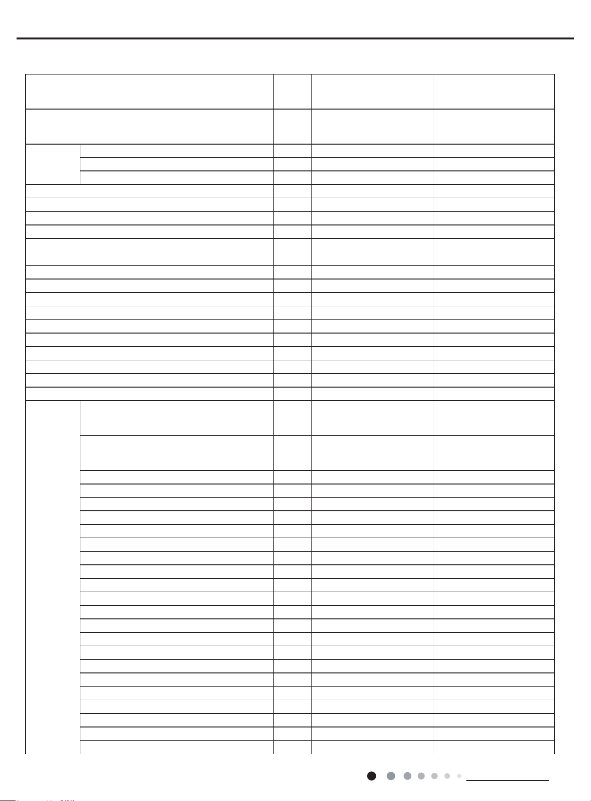
Service Manual
Model
Product Code
GWC36LB-D3DNA3G
GWC36LB-D3DNA5G
GWC36LB-D3DNB2G
CB171010900
CB169000900
CB433000300
GWH36LB-D3DNA3G
GWH36LB-D3DNA5G
GWH36LB-D3DNB2G
CB171010800
CB169001000
CB433000400
Rated Voltage V~ 208/230 208/230
Power Supply
Rated Frequency Hz 60 60
Phases 1 1
Power Supply Mode Outdoor Outdoor
Cooling Capacity(Min~Max) Btu/h 33600(7404~35997) 33600(7404~35997)
Heating Capacity(Min~Max) Btu/h / 34600(14979~35997)
Cooling Power Input(Min~Max) W 4100 4100(450~4300)
Heating Power Input(Min~Max) W / 3800(460~4300)
Cooling Power Current A 17 17
Heating Power Current A / 16.5
Rated Input W 4300 4300
Rated Current A 20 20
Air Flow Volume(SH/H/M/L) CFM 736/647/530/412 736/647/530/412
Dehumidifying Volume Pint/h 7.4 7.4
EER (Btu/h)/W 8.20 8.20
COP (Btu/h)/W / 9.11
SEER 18.00 18.00
SCOP / 9.00
Application Area yd
Model of indoor unit
Indoor Unit Product Code
2
55.01-83.72 55.01-83.72
GWC36LB-D3DNA3G/I
GWC36LB-D3DNA5G/I
GWC36LB-D3DNB2G/I
CB171N10900
CB169N00900
CB433N00300
GWH36LB-D3DNA3G/I
GWH36LB-D3DNA5G/I
GWH36LB-D3DNB2G/I
CB171N10800
CB169N01000
CB433N00400
Fan Type Cross-ow Cross-ow
Diameter Length(DXL) inch Φ4 1/4X20 9/16X2 Φ4 1/4X20 9/16X2
Fan Motor Cooling Speed (SH/H/M/L) r/min 1400/1250/1000/800 1400/1250/1000/800
Fan Motor Heating Speed (SH/H/M/L) r/min / 1400/1250/1050/850
Output of Fan Motor W 70 70
Fan Motor RLA A 0.4 0.4
Fan Motor Capacitor μF / /
Indoor Unit
Evaporator Form Aluminum Fin-copper Tube Aluminum Fin-copper Tube
Pipe Diameter inch Φ9/32 Φ9/32
Row-n Gap inch 2-1/16 2-1/16
Coil Length (LXDXW) inch 42 9/32X1X15X2 42 9/32X1X15X2
Swing Motor Model MP24BA MP24BA
Output of Swing Motor W 1.5 1.5
Fuse A 3.15 3.15
Sound Pressure Level (SH/H/M/L) dB (A) 54/49/44/37 54/49/44/37
Sound Power Level (SH/H/M/L) dB (A) 64/59/54/47 64/59/54/47
Dimension (WXHXD) inch 53 9/64X12 53/64X10 53 9/64X12 53/64X10
Dimension of Carton Box (LXWXH) inch 56 19/32X16 1/2X13 1/2 56 19/32X16 1/2X13 1/2
Dimension of Package (LXWXH) inch 56 3/4X16 9/16X14 56 3/4X16 9/16X14
Net Weight Ib 41.9 41.9
Gross Weight Ib 51.8 51.8
6
Technical Information

Service Manual
Outdoor Unit
Connection
Pipe
Model of Outdoor Unit GWC36LB-D3DNA3G/O(LC) GWH36LB-D3DNA3G/O(LCLH)
Outdoor Unit Product Code CB171W10900 CB171W10800
MITSUBISHI ELECTRIC
Compressor Manufacturer/Trademark
Compressor Model TNB306FPGMC TNB306FPGMC
Compressor Oil FV50S FV50S
Compressor Type Rotary Rotary
Compressor Locked Rotor Amp (L.R.A) 67.00 67.00
Compressor RLA A 13.50 13.50
Compressor Power Input W 3010 3010
Overload Protector CS01F272H01 CS01F272H01
Throttling Method Electron expansion valve Electron expansion valve
Operation temp ºF 61~86 61~86
Ambient temp (cooling) ºF 0~109 0~109
Ambient temp (heating) ºF / -4~75
Condenser Form Aluminum Fin-copper Tube Aluminum Fin-copper Tube
Pipe Diameter inch Φ5/16 Φ5/16
Rows-n Gap
Coil Length (LXDXW) inch 37X1 3/4X30 37X1 3/4X30
Fan Motor Speed rpm 890 890
Output of Fan Motor W 170 170
Fan Motor RLA A 0.89 0.89
Fan Motor Capacitor μF / /
Air Flow Volume of Outdoor Unit CFM 2589 2589
Fan Type Axial-ow Axial-ow
Fan Diameter inch Φ21 21/32 Φ21 21/32
Defrosting Method / Automatic Defrosting
Climate Type T1 T1
Isolation I I
Moisture Protection IP24 IP24
Design Pressure(High) PSIG 550 550
Design Pressure(Low) PSIG 240 240
Sound Pressure Level (H/M/L) dB (A) 65/-/- 65/-/-
Sound Power Level (H/M/L) dB (A) 75/-/- 75/-/-
Dimension (WXHXD) inch 39 1/2X31 7/64X16 13/16 39 1/2X31 7/64X16 13/16
Dimension of Carton Box (LXWXH) inch 42 1/2X19X33 42 1/2X19X33
Dimension of Package (LXWXH) inch 42 21/32X19 13/64X33 21/32 42 21/32X19 13/64X33 21/32
Net Weight Ib 154.4 161.0
Gross Weight Ib 165.4 172.0
Refrigerant R410A R410A
Refrigerant Charge oz 84.66 91.71
Length ft 24 39/64 24 39/64
Gas Additional Charge oz/ft 0.2 0.5
Outer Diameter Liquid Pipe inch Φ1/4 Φ1/4
Outer Diameter Gas Pipe inch Φ5/8 Φ5/8
Max Distance Height ft 32 3/16 32 3/16
Max Distance Length ft 98 27/64 98 27/64
Note:The connection pipe applies metric diameter.
inch
(GUANGZHOU)COMPRESSOR
CO. LTD
2-1/16
MITSUBISHI ELECTRIC
(GUANGZHOU)COMPRESSOR
CO. LTD
2-1/16
The above data is subject to change without notice; please refer to the nameplate of the unit.
Technical Information
7
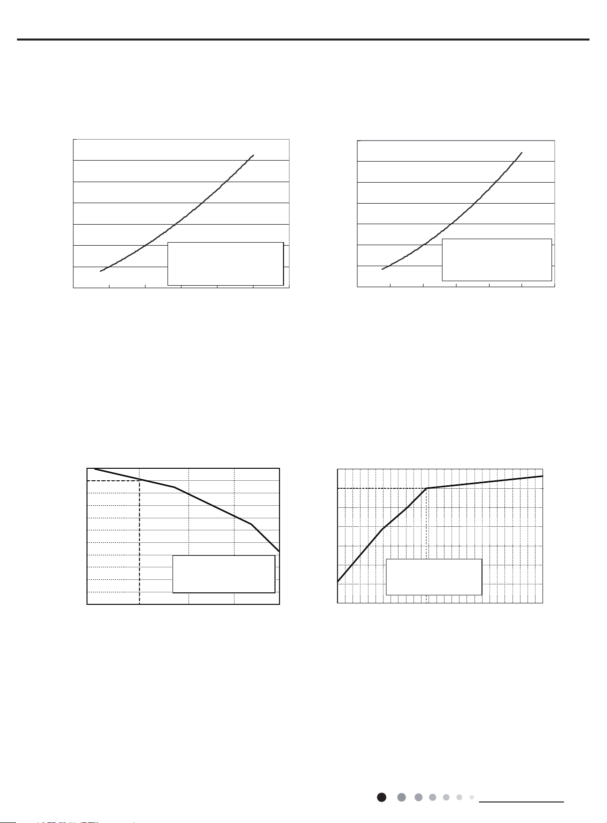
2.2 Operation Characteristic Curve
Cooling Heating
)O
Capacity ratio (%)
24K
120
Current(A)
Service Manual
Cooling
14
12
10
8
6
4
2
Conditio
Indoor:DB 80°F
n
WB66
°F
Indoor air flow: Super High
Pipe length:24 39/64ft
0
020406080100 120
Compressor Frequency(Hz)
Heating
14
12
10
8
6
Current(A)
4
Condition
Indoor:DB 70°F
2
Indoor air flow: Super High
Pipe length:24 39/64ft
0
020406080 100
Compressor Frequency(Hz)
2.3 Capacity Variation Ratio According to Temperature
105
100
95
90
85
80
75
70
65
60
55
50
90 95 100 105 110
Conditions
Indoor:
DB 80°F
Indoor air flow: Super High
Pipe length :
WB66
24 39/64ft
°F
Outdoor temp. (˚F
110
100
90
80
70
60
Capacity ratio (%)
50
40
-4 514
Conditions
Indoor:DB
Indoor air flow:Super High
Pipe length:
70°F
24 39/64ft
23 32 41 50
utdoor temp. (˚F)
8
Technical Information
Service Manual
Noise/dB(A)
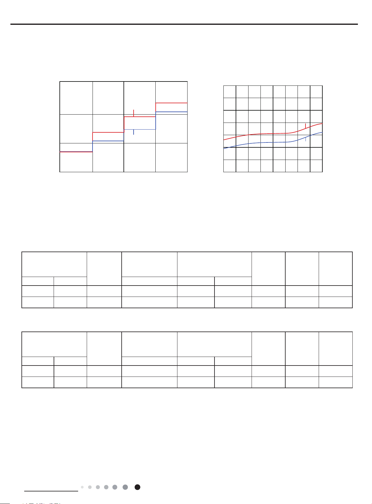
2.4 Noise Curve
Indoor side noise Outdoor side noise
60
50
40
30
36K
30K
LM
Indoor fan motor rating speed
HSH
80
75
70
65
60
Noise dB(A)
55
50
45
20 30 40 50 60 70 80 90 100
Compressor frequency(Hz)
36K
30K
2.5 Cooling and Heating Data Sheet in Rated Frequency
Cooling:
Rated cooling
condition(°F) (DB/WB)
Indoor Outdoor P (PSIG) T1 (°F) T2 (°F)
80/66 95/- 30K 130~145 46.8 to 52.8 127 to 96.8 Super High High 67
Model
Pressure of gas pipe
connecting indoor and
outdoor unit
Inlet and outlet pipe
temperature of heat
exchanger
Fan speed of
indoor unit
Fan speed of
outdoor unit
Compressor
revolution
(rps)
80/66
95/- 36K
Heating:
Rated heating
condition(°F) (DB/WB)
Indoor Outdoor P (PSIG) T1 (°F) T2 (°F)
70/- 20/19 30K 507~550 134.4 to 102 36 to 39 Super High High 61
70/- 20/19 36K 507~550 134.4 to 102 36 to 39 Super High High 58
Instruction:
T1: Inlet and outlet pipe temperature of evaporator
T2: Inlet and outlet pipe temperature of condenser
P: Pressure at the side of big valve
Connection pipe length: 24.6ft.
Model
130~145
Pressure of gas pipe
connecting indoor and
outdoor unit
46.8 to 52.8 127 to 96.8
Inlet and outlet pipe
temperature of heat
exchanger
Super High High
Fan speed of
indoor unit
Fan speed of
outdoor unit
60
Compressor
revolution
(rps)
Technical Information
9
1 37/64
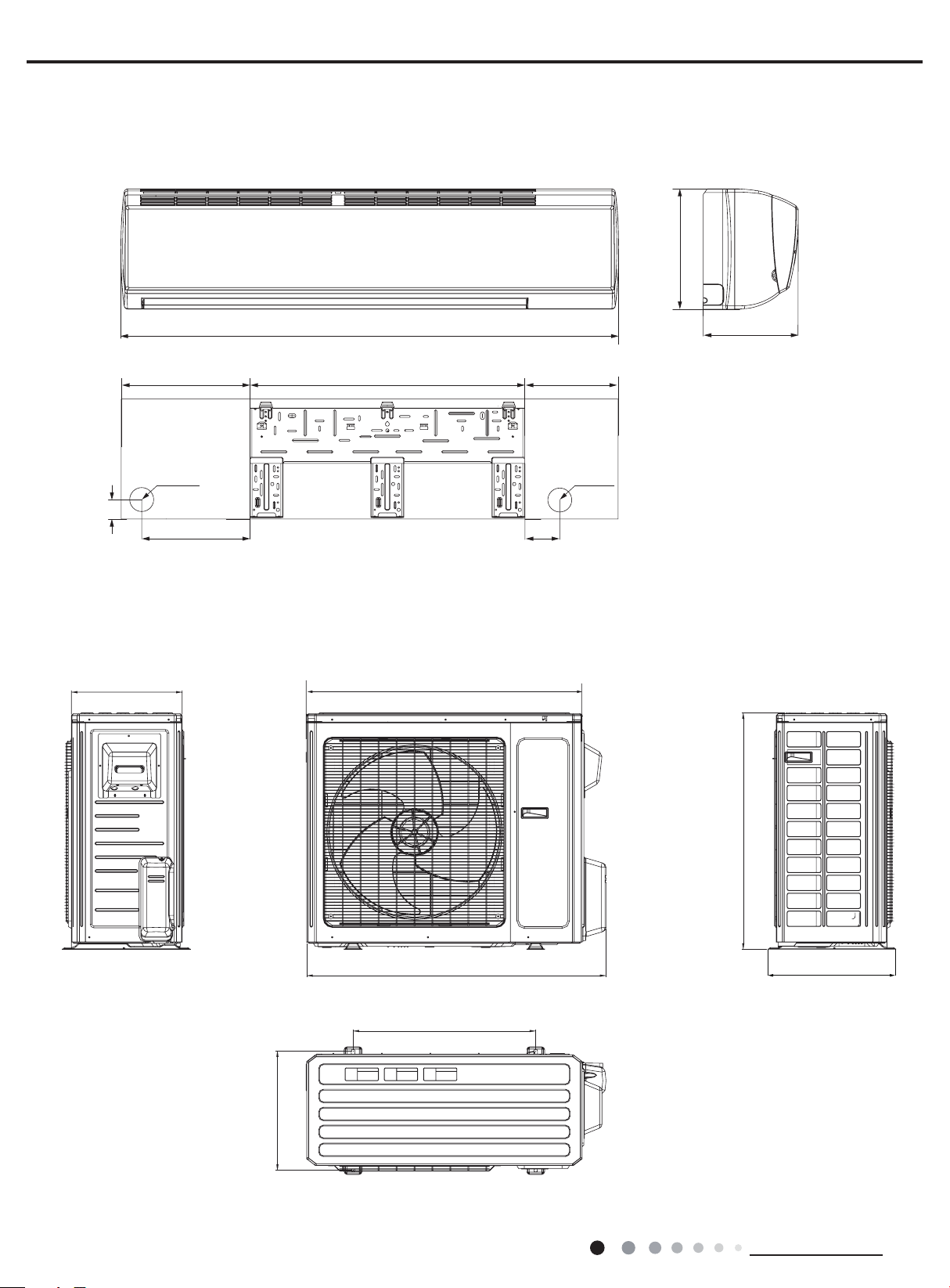
3. Outline Dimension Diagram
3.1 Indoor Unit
Service Manual
12 53/64
13 25/32 1029 3/8
Φ2 3/4
11 19/32
3.2 Outdoor Unit
14 37/64
53 9/64
36 2/9
3 1/2
10
Φ2 3/4
Unit:inch
10
15 9/16
39 1/2
24
31 7/64
16 13/16
Unit:inch
Technical Information
Service Manual
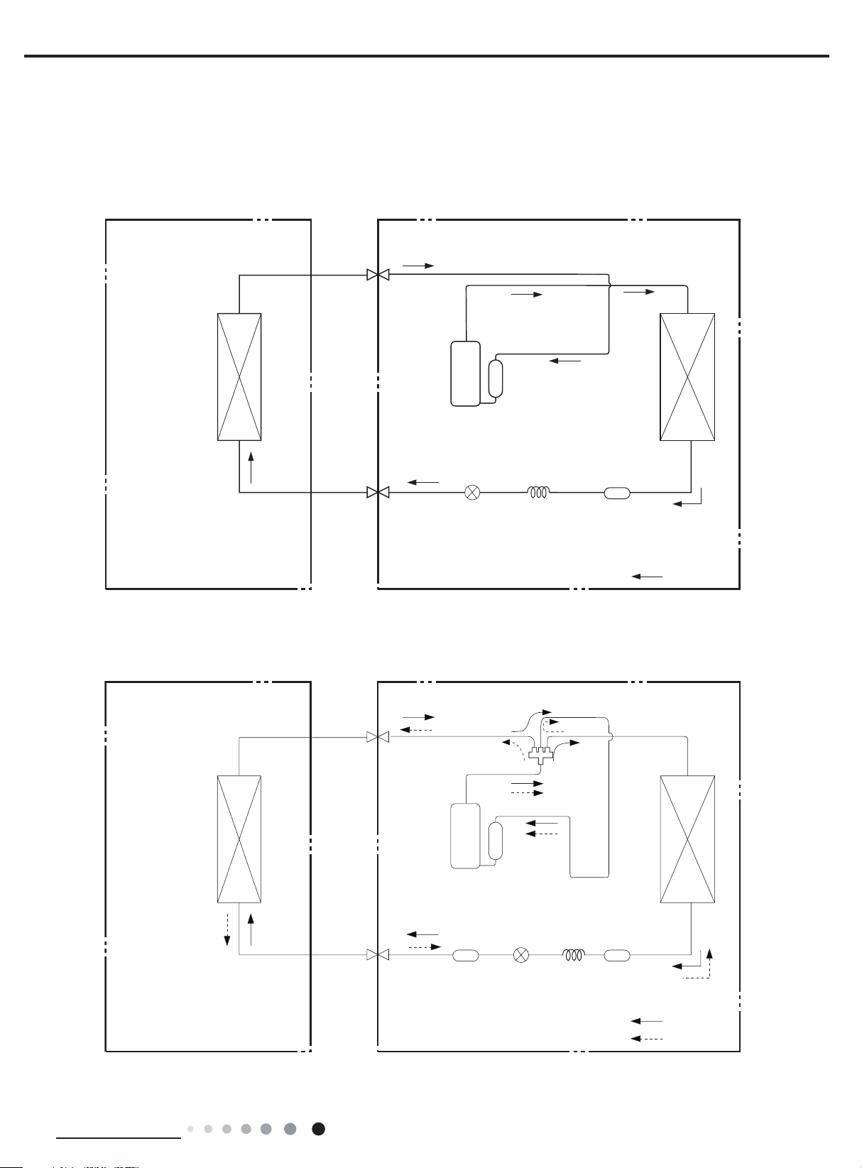
4. Refrigerant System Diagram
30K:
Cooling only model
Indoor unit
Heat
exchanger
(evaporator)
Outdoor unit
Gas pipe
side
Valve
Discharge
Suction
Compressor
Accumlator
Heat
exchanger
Liquid pipe
(condenser)
side
Valve
Electron
expansion
valve
Capillary
Strainer
COOLING
Cooling and heating model
Indoor unit
Heat
exchanger
(evaporator)
Gas pipe
side
Valve
Liquid pipe
side
Valve
Discharge
Suction
Compressor
Strainer
Outdoor unit
4-Way valve
Accumlator
Heat
exchanger
(condenser)
Electron
expansion
valve
Capillary
Strainer
COOLING
HEATING
Technical Information
11

36K:
Indoor unit
Outdoor unit
Cooling only model
Service Manual
Gas pipe
side
Valve
Heat
exchanger
(evaporator)
Cooling and heating model
Indoor unit
Liquid pipe
side
Valve
Gas pipe
side
Valve
Discharge
Suction
Compressor
Accumlator
Electron
expansion
valve
Outdoor unit
Heat
exchanger
(condenser)
Strainer
COOLING
4-Way valve
12
Heat
exchanger
(evaporator)
Connection pipe specication:
Liquid pipe:1/4 inch
Gas pipe:5/8 inch
Liquid pipe
side
Valve
Discharge
Suction
Compressor
Strainer
Accumlator
Electron
expansion
valve
Heat
exchanger
(condenser)
Strainer
COOLING
HEATING
Technical Information
Service Manual
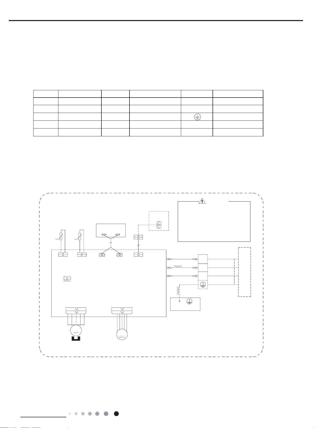
5. Electrical Part
5.1 Wiring Diagram
● Instruction
Symbol Symbol Color Symbol Symbol Color Symbol Name
WH White GN Green CAP Jumper cap
YE Yellow BN Brown COMP Compressor
RD Red BU Blue Grounding wire
YEGN Yellow/Green BK Black / /
VT Violet OG Orange / /
Note: Jumper cap is used to determine fan speed and the swing angle of horizontal lover for this model.
● Indoor Unit
52207(03
6(1625
78%(7(03
5757
78%(5220
&$3
-803
6:,1*8'
5(&(,9(5$1'
',63/$<%2$5'
6(1625
$3
',63',63
$3
0$,1%2$5'
'&02725
&1
:,5('
&21752//(5
$3
&211(&725
1
&20287
$&/
:$51,1*
3OHDVHGRQWWRXFKDQ\
HOHFWURQLFFRPSRQHQWRU
WHUPLQDOZKHQWKHPDFKLQH
LVUXQQLQJVWRSSLQJRUKDV
EHHQSRZHUHGRIIIRUOHVV
WKDQPLQXWHVWRSUHYHQW
HOHFWULFVKRFN
7(50,1$/%/2&.
1
;7
:+%8
%.
5'%1
*1<(*1
&211(&7,1*
&$%/(
%8
/
%.
%1
<(*1
/
*
(9$325$725
287'22581,7
Technical Information
0
6:,1*
02725
0
)$102725
63610000469
13
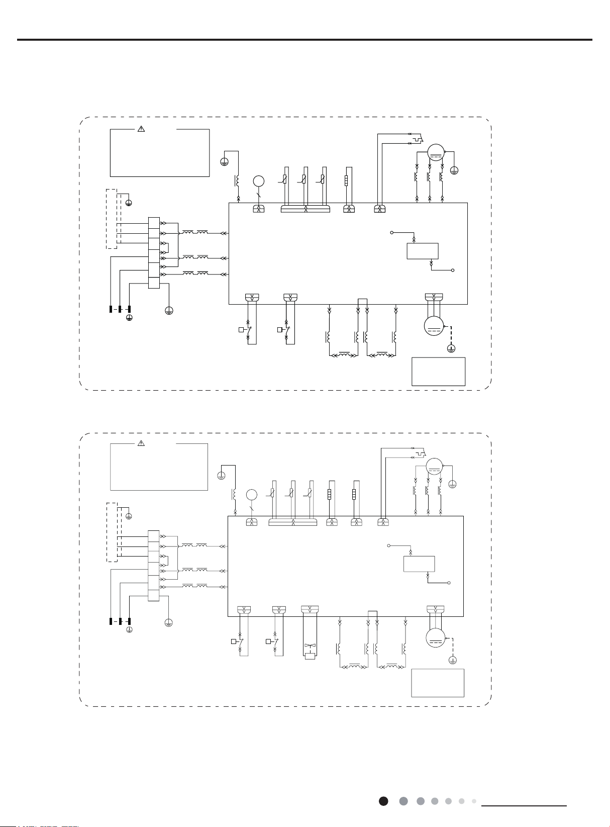
● Outdoor Unit
GWC30LB-D3DNA3G/O GWC30LB-D3DNA3H/O GWC36LB-D3DNA3G/O
Service Manual
*1<(*1
*
:+%8
%.
5'%1
%.%1
:+%8
*1<(*1
:$51,1*
7(50,1$/
%/2&.
1
/
/
*
;7
%8
%1
<(*1
0$*1(7,&
*
/
/
/
5,1*
<(*1
*
/
%.
/
%1
/
%8
/
(
&20
$&/
$&1
+3
35(6685(
(/(&7521,&
(;3$16,219$/9(
(.9
.
(9
35,17('&,5&8,7%2$5'
+33
+3
+,*+
6:,7&+
3OHDVHGRQWWRXFKDQ\
HOHFWURQLFFRPSRQHQWRU
WHUPLQDOZKHQWKHPDFKLQHLV
UXQQLQJVWRSSLQJRUKDVEHHQ
SRZHUHGRIIIRUOHVVWKDQ
PLQXWHVWRSUHYHQWWKHULVN
RIHOHFWULFVKRFN
,1'22581,7
//
32:(5
63610000470
GWH30LB-D3DNA3G/O GWH36LB-D3DNA3G/O
28778%(
+33
*2*2:+ :+
33
+,*+
35(6685(
6:,7&+
7(036(1625
(;+$867
7(036(1625
2875220
7(036(1625
575757
.
.
&1
$3
/1 /1
(+
+($7/
//
/
5($&725
&2035(6625
%$1'+($7(5
/3
5'
29&&203
/
5($&725
29(5/2$'3527(&725
6$7
0$*1(7,&
5,1*
//
5'
%8 <(
89:
%1
$&/
&20
.
:+%1%8 <(
/
/
127(
0RWRUJURXQGRQO\
DSSOLHVWRWKH
LURQVKHOOPRWRU
8
&203
9
/
5'
12
%1
2)$1'&
0
)$1
02725
&203
*
:
*
$&/
*
<(*1
<(*1
*
29(5/2$'3527(&725
%27720
%$1'+($7(5
5'
+($7/+($7/
29&&203
/3
%1%8
<( :+
/
/
0$*1(7,&
5,1*
5'
$&/
/
5($&725
6$7
8
/ /
8%(<
%1
&20
12
.
/1
/
127(
0RWRUJURXQGRQO\
DSSOLHVWRWKH
LURQVKHOOPRWRU
&203
9
/
5'
%1
2)$1'&
0
)$1
02725
&203
*
:
:98
$&/
*1<(*1
*
:+%8
%.
5'%1
%.%1
:+%8
*1<(*1
:$51,1*
7(50,1$/
%/2&.
1
/
/
*
;7
%8
%1
<(*1
3OHDVHGRQWWRXFKDQ\
HOHFWURQLFFRPSRQHQWRU
WHUPLQDOZKHQWKHPDFKLQHLV
UXQQLQJVWRSSLQJRUKDVEHHQ
SRZHUHGRIIIRUOHVVWKDQ
PLQXWHVWRSUHYHQWWKHULVN
RIHOHFWULFVKRFN
,1'22581,7
/ /
32:(5
6361000047001
0$*1(7,&
/
/
/
*
5,1*
<(*1
*
/
%.
/
%1
/
%8
(/(&7521,&
/
(.9
(
(9
&20
$&/
$&1
+33
+:+:2*2*
3 3
+3
+,*+
35(6685(
6:,7&+
7(036(1625
28778%(
2875220
(;3$16,219$/9(
57 57 57
.
7(036(1625
.
.
&1
$3
35,17('&,5&8,7%2$5'
:$<
7979
<9
:$<
9$/9(
+3
35(6685(
6:,7&+
+33
+,*+
7(036(1625
(;+$867
(+
%$1'+($7(5
&2035(6625
(+
/1
/ /
5($&725
The above data is subject to change without notice. Please refer to the nameplate of the unit.
<(*1
*
*
<(*1
*
14
Technical Information
Service Manual
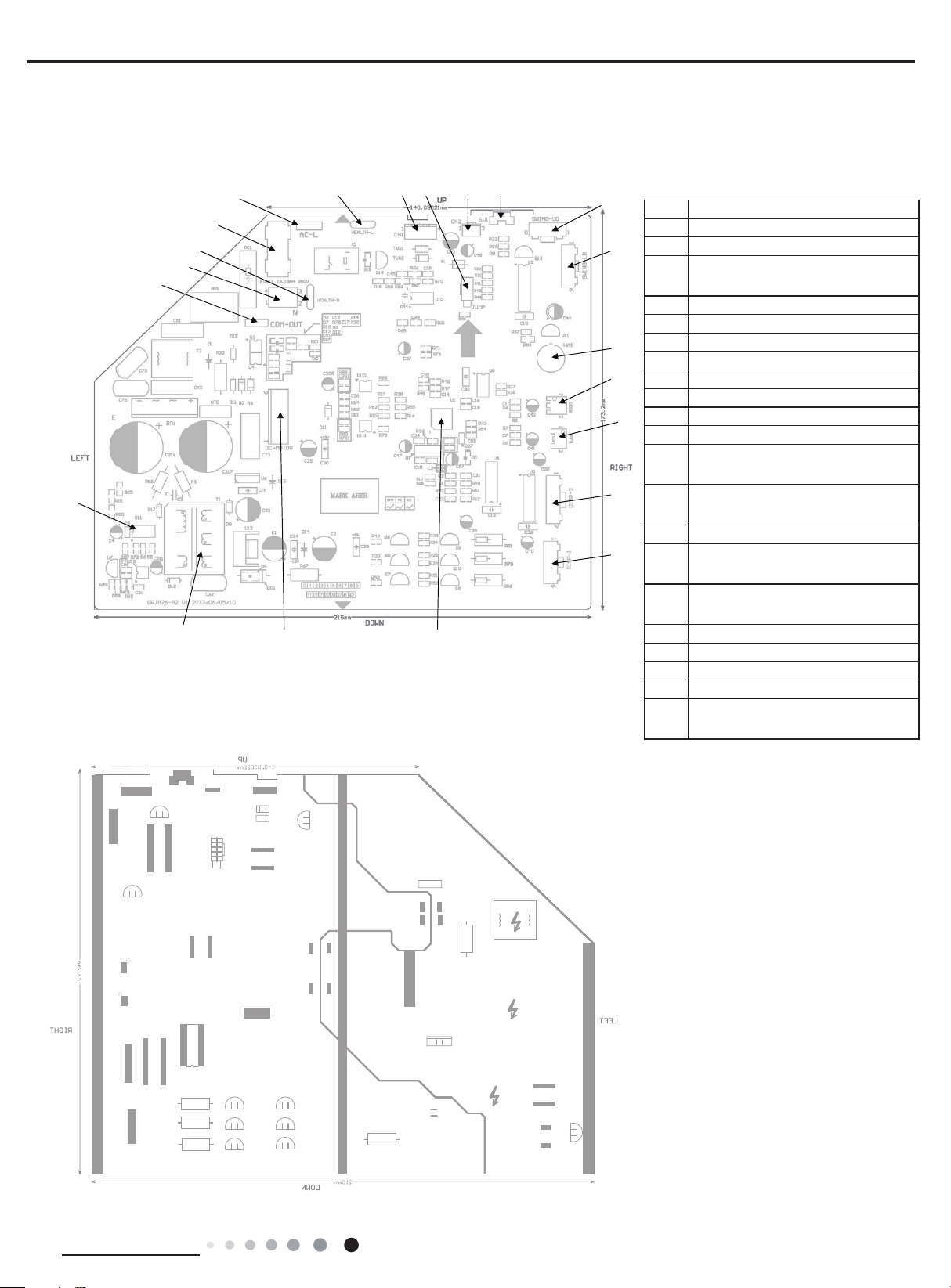
5.2 PCB Printed Diagram
Indoor Unit
● Top view
5
6
● Bottom view
1
2 2 2
3 3
4
17 18 19 20 21
16
No. Name
1 Power supply live wire
2 Fuse
Interface of neutral wire for health
3
function
15
4 Power supply neutral wire
5 Interface of communication
14
13
6 Power switch
7 High-frequency transformer
8 Interface of fan motor
9 Buzzer
12
11
10 Interface of display
11 Interface of display
Indoor tube temperature sensor
12
interface
Ambient temperature sensor
13
interface
14 Interface of wired controller
10
7
8
9
Interface of left and right swing
15
terminal
Interface of up and down swing
16
terminal
17 Auto button
18 Interface of BMS
19 Jumper cap
20 Interface of wired controller
Interface of live wire for health
21
function
Technical Information
15
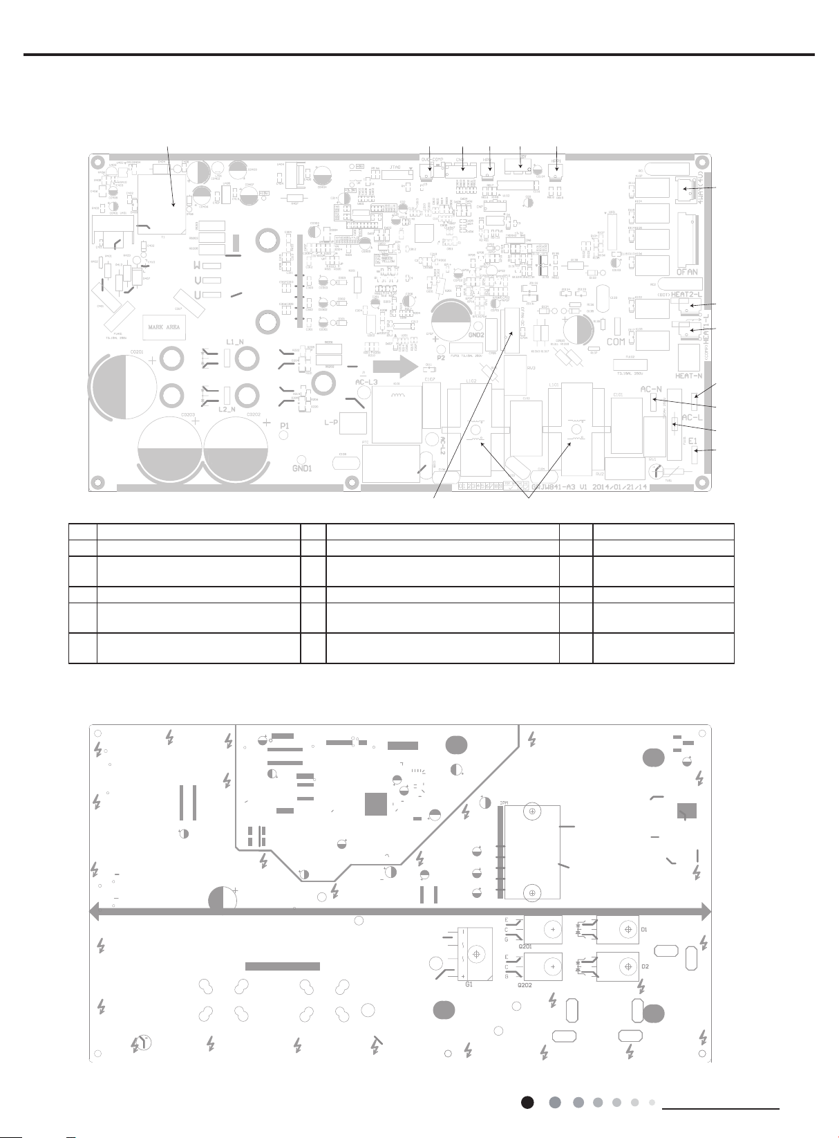
Outdoor Unit
1 2345 6
10
12
13
● Top view
Service Manual
1415
No. Name No. Name No. Name
1 High-frequency transformer T1 6 High pressure protection terminal HPP1 11 Terminal of neutral wire
Overload protection terminal of
2
compressor OVC-COMP
3 Terminal of temp sensor CN2 8 Electric heater band of chassis HEAT2-L 13 Terminal of ground wire
High pressure protection terminal
4
HPP
Electronic expansion valve terminal
5
EV
7 Terminal of 4-way valve 12 Protective tube FU101
Electric heater band of compressor
9
HEAT1-L
10 Terminal of live wire 15
14 Choke L 101 and L102
Terminal of outdoor fan
OFAN-DC
7
8
9
11
● Bottom view
16
Technical Information
Service Manual
6. Function and Control
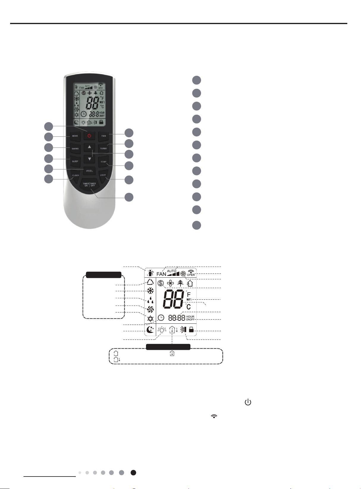
6.1 Remote Controller Introduction
1
2
4
7
9
11
3
5
6
8
10
1
ON/OFF button
2
MODE button
3
FAN button
4
SWING button
5
TURBO button
6
▲/ button
7
SLEEP button
8
TEMP button
9
I FEEL button
▲
12
Introduction for icons on display screen
I feel
Operation mode
Auto mode
Cool mode
Dry mode
Fan mode
Heat mode
Clock
Sleep mode
Light
:Set temp.
:Outdoor ambient temp.
Temp. display type
:Indoor ambient temp.
10
LIGHT button
11
CLOCK button
TIMER ON / TIMER OFF
12
button
Set fan speed
Send signal
Turbo mode
8℃ heating function
WIFI(This unit without WiFi fuction)
Set temperature
Set time
TIMER ON / TIMER OFF
Child lock
Up & down swing
Introduction for buttons on remote controller
Note:
● After putting through the power, the air conditioner will give out a sound. Operation indictor " " is ON (red indicator). After that,
you can operate the air conditioner by using remote controller.
●
Under on status, pressing the button on the remote controller, the signal icon " "
and the air conditioner will give out a “de” sound, which means the signal has been sent to the air conditioner.
● Under off status, set temperature and clock icon will be displayed on the display
of remote controller (If timer on, timer off and light functions are set, the corre- sponding icons will be displayed on the display of
remote controller at the same
time); Under on status, the display will show the corresponding set function icons.
Technical Information
on the display of remote controller will blink once
17
Service Manual
1. ON/OFF button
Press this button can turn on or turn off the air conditioner. After turning on the air conditioner, operation indicator " "on indoor unit’s
display is ON (green indicator. The colour is different for different models), and indoor unit will give out a sound.
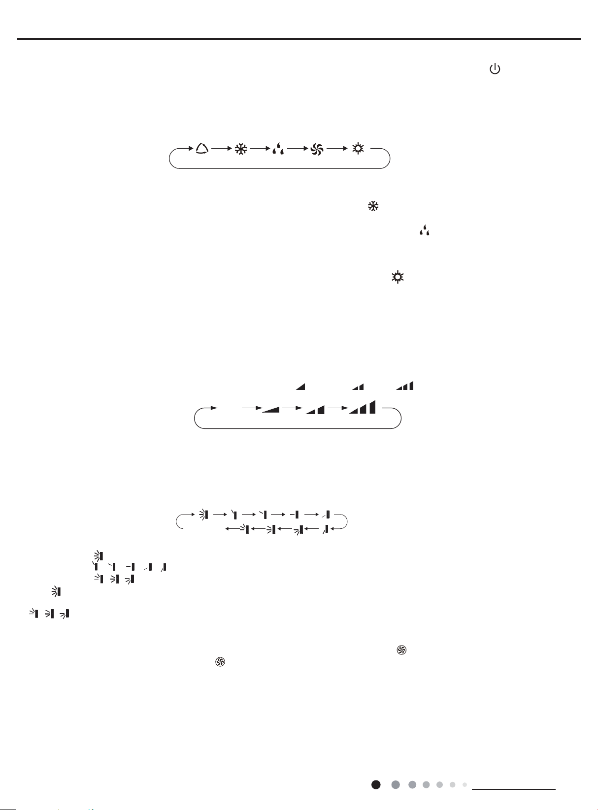
2. MODE button
Press this button to select your required operation mode.
AUTO
● When selecting auto mode, air conditioner will operate automatically according to ex-factory setting. Set temperature can’t be adjusted and
will not be displayed as well. Press "FAN" button can adjust fan speed. Press "SWING" button can adjust fan blowing angle.
● After selecting cool mode, air conditioner will operate under cool mode. Cool indicator " "on indoor unit is ON. Press "▲" or " ▲ " button
to adjust set temperature. Press "FAN" button to adjust fan speed. Press "SWING" button to adjust fan blowing angle.
● When selecting dry mode, the air conditioner operates at low speed under dry mode. Dry indicator " " on indoor unit is ON. Under dry
mode, fan speed can’t be adjusted. Press "SWING" button to adjust fan blowing angle.
● When selecting fan mode, the air conditioner will only blow fan, no cooling and no heating. All indicators are OFF. Press "FAN" button to
adjust fan speed. Press "SWING" button to adjust fan blowing angle.
● When selecting heating mode, the air conditioner operates under heat mode. Heat indicator " " on indoor unit is ON. Press "▲" or " ▲ "
button to adjust set temperature. Press "FAN" button to adjust fan speed. Press "SWING" button to adjust fan blowing angle. (Cooling only
unit won’t receive heating mode signal. If setting heat mode with remote controller, press ON/OFF button can’t start up the unit).
Note:
● For preventing cold air, after starting up heating mode, indoor unit will delay 1~5 minutes to blow air (actual delay time is depend on indoor
ambient temperature).
● Set temperature range from remote controller: 16~30℃ (60.8~86.0OF); Fan speed: auto, low speed, medium speed, high speed.
3. FAN button
Pressing this button can set fan speed circularly as: auto (AUTO), low( ) ,medium( ), high( ).
COOL
DRY HEAT
FAN
Auto
Caution:
● Under AUTO speed, air conditioner will select proper fan speed automatically according to ex-factory setting.
● Fan speed under dry mode is low speed.
4. SWING button
Press this button can select up&down swing angle. Fan blow angle can be selected circularly as below:
no display
(horizontal louvers stops at current position)
● When selecting " ", air conditioner is blowing fan automatically. Horizontal louver will automatically swing up & down at maximum angle.
● When selecting " 、 、 、 、 ", air conditioner is blowing fan at xed position. Horizontal louver will stop at the xed position.
● When selecting " 、 、 " , air conditioner is blowing fan at xed angle. Horizontal louver will send air at the xed angle.
● Hold " "button above 2s to set your required swing angle. When reaching your required angle, release the button.
Note:
● " 、 、 " may not be available. When air conditioner receives this signal, the air conditioner will blow fan automatically.
5. TURBO button
Under COOL or HEAT mode, press this button to turn to quick COOL or quick HEAT mode. " " icon is displayed on remote controller.
Press this button again to exit turbo function and " " icon will disappear.
6. ▲/▲ button
● Press "▲" or "▲" button once increase or decrease set temperature 1℃(33.8OF). Holding "▲" or "▲" button, 2s later, set temperature
on remote controller will change quickly. On releasing button after setting is finished, temperature indicator on indoor unit will change
accordingly. (Temperature can’t be adjusted under auto mode)
● When setting TIMER ON, TIMER OFF or CLOCK, press "▲" or "▲" button to adjust time. (Refer to CLOCK, TIMER ON, TIMER OFF
buttons) When setting TIMER ON, TIMER OFF or CLOCK, press "▲" or "▲" button to adjust time. (Refer to CLOCK, TIMER ON, TIMER
OFF buttons)
18
Technical Information
Service Manual
7. SLEEP button
Under COOL, HEAT or DRY mode, press this button to start up sleep function. " " icon is displayed on remote controller. Press this button
again to cancel sleep function and " " icon will disappear.
8. TEMP button
By pressing this button, you can see indoor set temperature, indoor ambient temperature or outdoor ambient temperature on indoor unit’s
display. The setting on remote controlleris selected circularly as below:
no display
● When selecting " " or no display with remote controller, temperature indicator on indoor unit displays set temperature.
● When selecting " " with remote controller, temperature indicator on indoor unit displays indoor ambient temperature.
● When selecting " " with remote controller, temperature indicator on indoor unit displays outdoor ambient temperature.
Note:
●
Outdoor temperature display is not available for some models. At that time, indoor
temperature.
● It’s defaulted to display set temperature when turning on the unit.There is no display in the remote controller.
● Only for the models whose indoor unit has dual-8 display.
● When selecting displaying of indoor or outdoor ambient temperature, indoor temperature indicator displays corresponding temperature and
automatically turn to display set temperature after three or ve seconds.
unit receives " "signal, while it displays indoor set
9. I FEEL button
Press this button to start I FEEL function and " " will be displayed on the remote controller. After this function is set, the remote controller
will send the detected ambient temperature to the controller and the unit will automatically adjust the indoor temperature according to the
detected temperature. Press this button again to close I FEEL function and " " will disappear.
● Please put the remote controller near user when this function is set. Do not put the remote controller near the object of high temperature
or low temperature in order to avoid detecting inaccurate ambient temperature.
10. LIGHT button
Press this button to turn off display light on indoor unit. " " icon on remote controller disappears. Press this button again to turn on
display light. " " icon is displayed.
11. CLOCK button
Press this button to set clock time. " " icon on remote controller will blink. Press "▲" or "▲" button within 5s to set clock time. Each
pressing of "▲" or "▲" button, clock time will increase or decrease 1 minute. If hold "▲" or "▲" button, 2s later, time will change quickly.
Release this button when reaching your required time. Press "CLOCK" button to conrm the time. " " icon stops blinking.
Note:
● Clock time adopts 24-hour mode.
● The interval between two operation can’t exceeds 5s. Otherwise, remote controller will quit setting status. Operation for TIMER ON/TIMER
OFF is the same.
12. TIMER ON / TIMER OFF button
● TIMER ON button
"TIMER ON" button can set the time for timer on. After pressing this button, " " icon disappears and the word "ON" on remote controller
blinks. Press "▲" or "▲"button to adjust TIMER ON setting. After each pressing "▲" or "▲" button, TIMER ON setting will increase or
decrease 1min. Hold "▲" or "▲" button, 2s later, the time will change quickly until reaching your required time. Press "TIMER ON" to
conrm it. The word "ON" will stop blinking. " " icon resumes displaying. Cancel TIMER ON: Under the condition that TIMER ON is
started up, press "TIMER ON" button to cancel it.
● TIMER OFF button
"TIMER OFF" button can set the time for timer off. After pressing this button," " icon disappears and the word "OFF" on remote
controller blinks. Press "▲" or "▲" button to adjust TIMER OFF setting. After each pressing "▲" or "▲" button,
TIMER OFF setting will increase or decrease 1min. Hold "▲" or "▲" button, 2s later, the time will change quickly until reaching your
required time. Press "TIMER OFF" word "OFF" will stop blinking. " " icon resumes displaying. Cancel TIMER OFF. Under the condition
that TIMER OFF is started up, press "TIMER OFF" button to cancel it.
Note:
● Under on and off status, you can set TIMER OFF or TIMER ON simultaneously.
● Before setting TIMER ON or TIMER OFF, please adjust the clock time.
● After starting up TIMER ON or TIMER OFF, set the constant circulating valid. After that, air conditioner will be turned on or turned off
according to setting time. ON/OFF button has no effect on setting. If you don’t need this function, please use remote controller to cancel it.
Technical Information
19
Service Manual
Function introduction for combination buttons
1. Energy-saving function
Under cooling mode, press "TEMP" and " CLOCK" buttons simultaneously to start up or turn off energy-saving function. When energy-saving
function is started up, "SE" will be shown on remote controller, and air conditioner will adjust the set temperature automatically according to
ex-factory setting to reach to the best energy-saving effect. Press "TEMP" and "CLOCK"buttons simultaneously again to exit energy-saving
function.
Note:
● Under energy-saving function, fan speed is defaulted at auto speed and it can’t be adjusted.
●
Under energy-saving function, set temperature can’t be adjusted. Press "TURBO"
● Sleep function and energy-saving function can’t operate at the same time. If energy-saving function has been set under cooling mode,
press sleep button will cancel energy-saving function. If sleep function has been set under cooling mode, start up the energy-saving
function will cancel sleep function.
2. 8 ℃ heating function
Under heating mode, press "TEMP" and "CLOCK" buttons simultaneously to start
started up, " " and "8℃" will be shown on remote controller, and the air conditioner keep the heating status
"CLOCK" buttons simultaneously again to exit 8℃heating function.
Note:
● Under 8℃ heating function, fan speed is defaulted at auto speed and it can’t be adjusted.
● Under 8℃ heating function, set temperature can’t be adjusted. Press "TURBO" button and the remote controller won’t send signal.
● Sleep function and 8℃ heating function can’t operate at the same time. If 8℃heating function has been set under cooling mode, press
sleep button will cancel 8℃ heating function. If sleep function has been set under cooling mode, start up the 8℃ heating function will
cancel sleep function.
● Under ℉ temperature display, the remote controller will display 46℉ heating.
button and the remote controller won’t send signal.
up or turn off 8℃ heating function. When this function is
at 8℃. Press "TEMP" and
3. Child lock function
Press "▲" and "▲" simultaneously to turn on or turn off child lock function. When child lock function is on, " " icon is displayed on remote
controller. If you operate the remote controller, the " " icon will blink three times without sending signal to the unit.
4. Temperature display switchover function
Under OFF status, press "▲" and "MODE" buttons simultaneously to switch temperature display between ℃ and ℉.
5. WIFI fuction (This unit is without WiFi fuction)
Under ON status, press "Mode" and "Turbo" button simultaneously,the "WiFi" icon will be displayed on remote controller.Press
"Mode"and"Turbo" button simultaneously,the "WiFi" icon will disppear.
Operation guide
1. After putting through the power, press "ON/OFF" button on remote controller to turn on the air conditioner.
2. Press "MODE" button to select your required mode: AUTO, COOL, DRY, FAN, HEAT.
3. Press "▲" or "▲" button to set your required temperature. (Temperature can’t be adjusted under auto mode).
4. Press "FAN" button to set your required fan speed: auto, low, medium and high speed.
5. Press "SWING" button to select fan blowing angle.
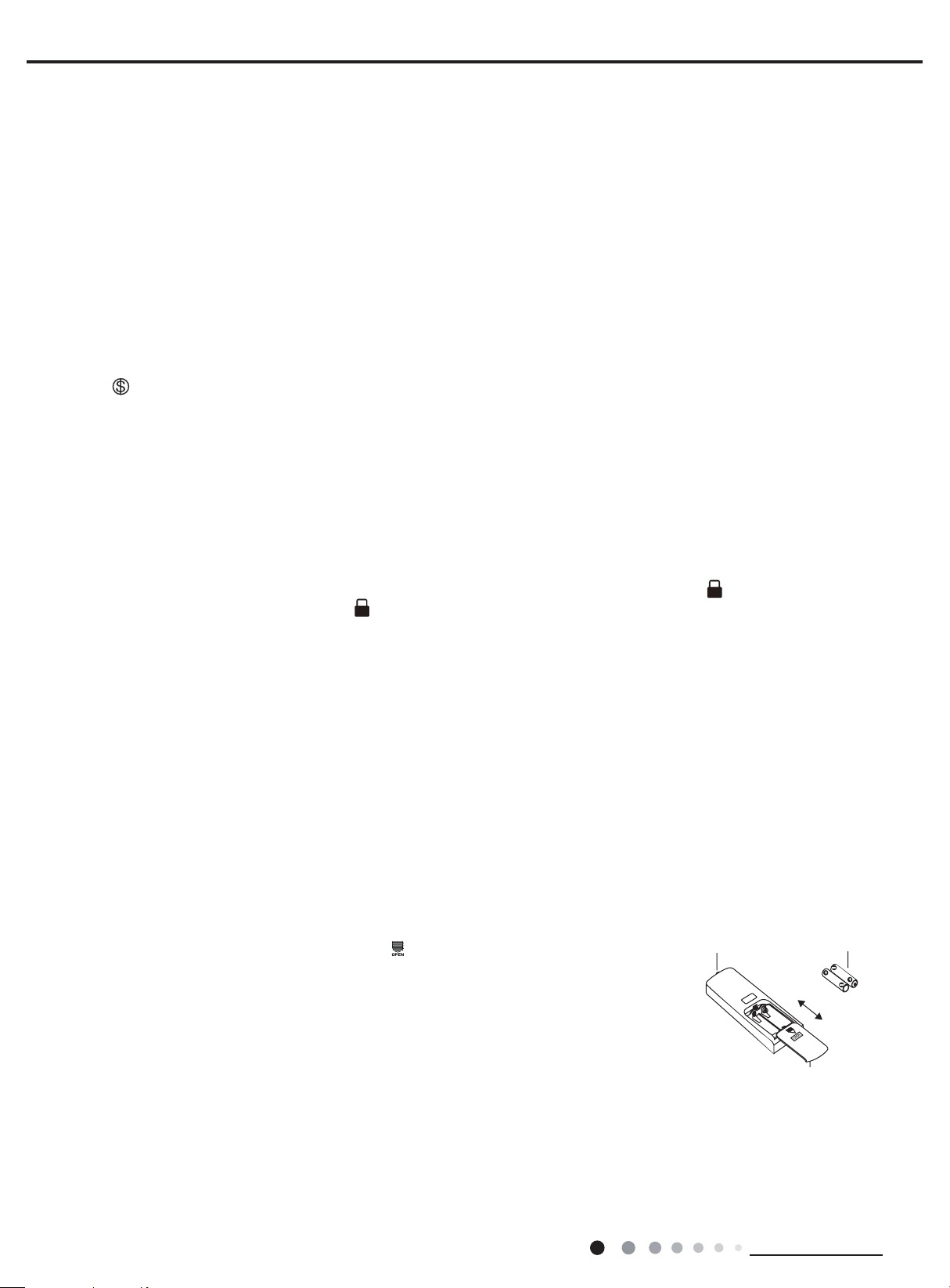
Replacement of batteries in remote controller
1. Press the back side of remote controller marked with " ", as shown in the g, and then push
out
the cover of battery box along the arrow direction.
2. Replace two 7# (AAA 1.5V) dry batteries, and make sure the position of "+" polar and "-" polar
are correct.
3. Reinstall the cover of battery box.
signal sender battery
reinstall
remove
Note:
● During operation, point the remote control signal sender at the receiving window on indoor unit.
● The distance between signal sender and receiving window should be no more than 8m, and there should be no obstacles between them.
● Signal may be interfered easily in the room where there is uorescent lamp or wireless telephone; remote controller should be close to
indoor unit during operation.
● Replace new batteries of the same model when replacement is required.
● When you don’t use remote controller for a long time, please take out the batteries.
● If the display on remote controller is fuzzy or there’s no display, please replace batteries.
20
Cover of battery box
Technical Information
Service Manual
Tpreset +3˚F
6.2 Brief Description of Modes and Functions
1. Temperature Parameters
Indoor preset temperature(Tpreset)
Indoor ambient temperature (Tamb.)
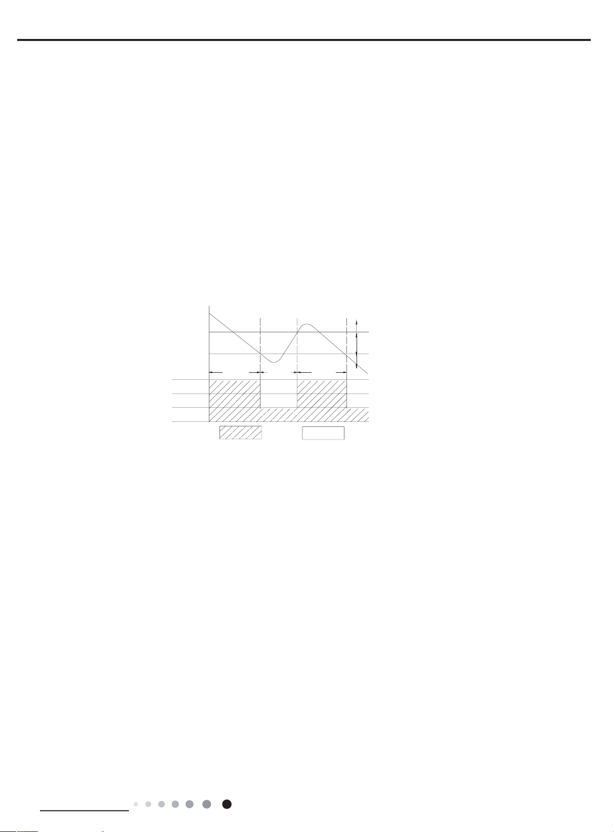
2. Basic Functions
Once energized, in no case should the compressor be restarted within less than 3 minutes. In the situation that memory functionis
available, for the rst energization, if the compressor is at stop before de-energization, the compressor will be started withouta 3-minute
lag; if the compressor is in operation before de-energization, the compressor will be started with a 3-minute lag; andonce started, the
compressor will not be stopped within 6 minutes regardless of changes in room temperature;
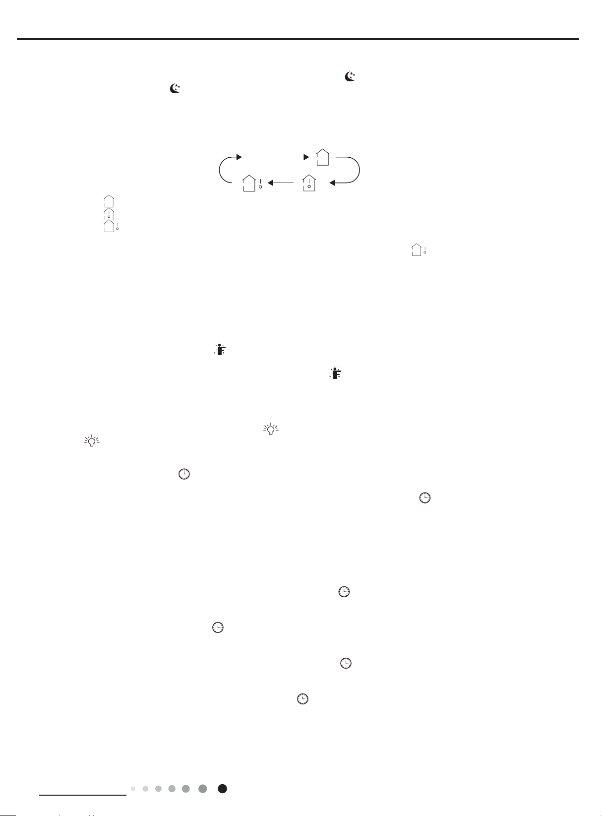
(1) Cooling Mode
Working conditions and process of cooling
①
When Tamb. ≥ Tpreset, the unit will enter cooling operation, in which case the indoor fan, the outdoor fan and the compressor willwork and
the indoor fan will run at preset speed.
When Tamb. ≤ Tpreset -3.6°F, the compressor will stop, the outdoor fan will stop with a time lag of 60s, and the indoor fan will run atpreset
speed.
When Tpreset-3.6°F < Tamb.< Tpreset+1.8°F, the unit will remain at its previous state.
Under this mode, the four-way valve will be de-energized and temperature can be set within a range from 61°F~86°F. If the compressor is
shut down for some reason, the indoor fan and the swing device will operate at original state.
Start cooling
Original working state
Stop cooling
Protection
②
Tpreset
Compressor
Outdoor fan
Indoor fan
Tamb.
≥ 6 min.≥ 3 min. ≥ 6 min.
Set fan speed
Run
Stop
Antifreeze protection
Under cooling and dehumidifying mode, 6 minutes after the compressor is started:
If Tevap ≤ 35.6°F, the compressor will operate at reduced frequency.
If Tevap ≤ 30.2°F is detected for durative 3 minutes, the compressor will stop, and after 60 seconds, the outdoor fan will stop;and under
cooling mode, the indoor fan and the swing motor will remain at the original state.
If Tevap. ≥ 42.8°F and the compressor has remained at OFF for at least 3 minutes, the compressor will resume its original operation state.
Total current up and frequency down protection
If I
≤ 16A, frequency rise will be allowed; if I
total
frequency; and if I
≥ 20A, the compressor will stop and the outdoor fan will stop with a time lag of 60s.
total
≥ 17A, frequency rise will not be allowed; if I
total
≥ 18A, the compressor will run at reduced
total
(2) Dehumidifying Mode
Working conditions and process of dehumidifying
①
If Tamb. > Tpreset+1.8°F, the unit will enter cooling and dehumidifying mode, in which case the compressor and the outdoor fan will
operate and the indoor fan will run at low speed.
If Tpreset -3.6°F ≤ Tamb. ≤ Tpreset+1.8°F, the compressor remains at its original operation state.
If Tamb.< Tpreset-3.6°F , the compressor will stop, the outdoor fan will stop with a time lag of 60s, and the indoor fan will
operate at low speed.
Protection
②
Protection is the same as that under the cooling mode.
(3) Heating Mode
Working conditions and process of heating
①
If Tamb. ≤ Tpreset+3.6°F, the unit enters heating mode, in which case the four-way valve, the compressor and the outdoor fan willoperate
simultaneously, and the indoor fan will run at preset speed in the condition of preset cold air prevention.
If Tamb. ≥ Tpreset+9°F, the compressor will stop, the outdoor fan will stop with a time lag of 60s, and the indoor fan will stop after
60-second blow at low speed.
If Tpreset+3.6°F < Tamb. < Tpreset+9°F, the unit will maintain its original operating status.
Under this mode, the four-way valve is energized and temperature can be set within a range of 61°F~86°F. The operatingsymbol, the
heating symbol and preset temperature are revealed on the display.
Condition and process of defrost
②
Technical Information
21

Service Manual
When duration of successive heating operation is more than 45 minutes, or accumulated heating time more than 90 minutes, andone of the
following conditions is reached, the unit will enter the defrost mode after 3 minutes.
a. Toutdoor amb. ≥ 41°F, Toutdoor pipe ≤ 28.4°F; b. 28.4°F ≤ Toutdoor amb.
c. 23.4°F < Toutdoor amb. ≤ 28.4°F, Toutdoor pipe ≤ 17.6°F;
d. 14°F < Toutdoor amb. < 23°F, Toutdoor pipe- Tcompensation ≤ Toutdoor amb.-5.4°F;
e. Toutdoor amb. < 14°F, Toutdoor pipe- Tcompensation ≤ Toutdoor amb.-5.4°F;
After energization, when defrosting for the first time Tcompensation=0°F. If it is not the firstly time for defrosting, the Tcompensation is
determined by the Toutdoor pipe of last time quitting defrosting.
a. Toutdoor pipe > 35.6°F, Tcompensation=0°F; b. Toutdoor pipe ≤ 35.6°F, Tcompensation=5.4° F.
At that time, the indoor fan stops and the compressor stops, and after 60 seconds the outer fan will stop, and then after 30seconds, the fourway valve will stop. After 30 seconds, the compressor is initiated for raising the frequency to defrost frequency.
When the compressor has operated under defrost mode for 10 minutes, or Touter tube ≥ 50°F, the compressor will be converted to 46Hz
operation.After 30 seconds, the compressor will stop. And after another 30 seconds, the four-way valve will be opened, and after60 seconds,
the compressor and the outer fan will be started, the indoor fan will run under preset cold air prevention conditions,and H1 will be displayed
at temperature display area on the display panel. Defrost frequency is 70 Hz.
3.Protection
Cold air prevention
The unit is started under heating mode (the compressor is ON):
In the case of Tindoor amb. < 75°F: if T tube ≤ 104°F and the indoor fan is at stop state, the indoor fan will begin to run at low speed witha
①
time lag of 2 minutes. Within 2 minutes, if T tube > 104°F, the indoor fan also will run at low speed; and after 1 minute operation atlow speed,
the indoor fan will be converted to operation at preset speed. Within 1 minute low speed operation or 2 minute non-operation, if T tube >
108°F, the fan will run at present speed.
In the case of Tindoor amb. < 75°F: if Ttube ≤ 108°F, the indoor fan will run at low speed, and after one minute, the indoor fan will
②
beconverted to preset speed. Within 1 minute low speed operation, if Ttube > 104°F, the indoor fan will be converted to preset speed.Note:
Tindoor amb. indicated in① and②refers to, under initially heating mode, the indoor ambient temperature before the command to start the
compressor is performed according to the program, or after the unit is withdrawn from defrost, the indoor ambient temperature before the
defrost symbol is cleared.
Total current up and frequency down protection
If the total current I
≤ 16A, frequency rise will be allowed; if I
total
≥ 17A,frequency rise will not be allowed; if Itotal18A,the compressorwill run
total
at reduced frequency; and if Itotal20A, the compressor will stop and the outdoor fan will stop with a time lag of 60s.
(4) Fan Mode
Under the mode, the indoor fan will run at preset speed and the compressor, the outdoor fan, the four-way valve and the electricheater will
stop.
Under the mode, temperature can be set within a range of 61°F~86°F.
(5) AUTO Mode
Working conditions and process of AUTO mode
①
Under AUTO mode, standard cooling temperature Tpreset is 77°F and standard heating temperature Tpreset is 68°F.
a. Once energized, if Tamb. ≤ 71.6°F, the unit will be started under heating mode; if 71.6°F < Tamb.< 78.8°F, the unit will run under fanmode
and the run indicator will be bright; and if Tamb. ≥ 78.8°F, the unit will be started under cooling mode.
b.Under AUTO mode,if Tamb. ≥ Tpreset +1.8ºF is detected,the unit will select to run under cooling mode,in which case implicit
presettemperature is 77°F; if Tamb. ≤ Tpreset-1.8°F, the compressor will stop, the outdoor fan will stop with a time lag of 1 minute,
andtheindoor fan will run at preset speed; and if Tpreset-1.8°F < Tamb. < Tpreset+1.8ºF, the unit will remain at its original state.
c.Under AUTO mode, if Tamb. ≤ Tpreset+3.6°F is detected, the unit will select to run under heating mode, in which case implicit preset
temperature is 64°F; if Tamb. ≥ Tpreset+9°F, the compressor will stop, the outdoor fan will stop with a time lag of 1 minute,and the indoor
fan will run under the mode of residue heat blowing; and if Tpreset+3.6°F < Tamb.< Tpreset+41°F, the unit will remainatits original state. The
cooling-only unit will run under fan mode.
d.Under AUTO mode, if 71.6°F < Tamb.< 78.8°F, the unit will remain at its original state.
Protection
②
a. In cooling operation, protection is the same as that under the cooling mode;
b. In heating operation, protection is the same as that under the heating mode;
c. When ambient temperature changes, operation mode will be converted preferentially. Once started, the compressor willremain unchanged
for at least 6 minutes.
(6) Common Protection Functions and Fault Display under COOL, HEAT, DRY and AUTO Modes
Overload protection
①
Ttube:measured temperature of outdoor heat exchanger under cooling mode; and measured temperature of indoor heat ex-changer under
heating mode.
1) Cooling overloada.
a. If Ttube ≤ 126°F, the unit will return to its original operation state.
b. If Ttube ≥ 131°F, frequency rise is not allowed.
22
Technical Information
Service Manual
c. If Ttube ≥ 136°F, the compressor will run at reduced frequency.
d. If Ttube ≥ 144°F, the compressor will stop and the indoor fan will run at preset speed.
2) Heating overload
a. If Ttube ≤ 126°F, the unit will return to its original operation state.
b. If Ttube ≥ 131°F, frequency rise is not allowed.
c. If Ttube ≥ 136°F, the compressor will run at reduced frequency.
d. If Ttube ≥ 144°F,the compressor will stop and the indoor fan will blow residue heat and then stop.
Exhaust temperature protection of compressor
②
If exhaust temperature ≥ 208°F, frequency is not allowed to rise.
If exhaust temperature ≥ 217°F, the compressor will run at reduced frequency.
If exhaust temperature ≥ 230°F, the compressor will stop.
If exhaust temperature ≤ 194°F, the compressor has stayed at stop for at least 3 minutes, the compressor will resume itsoperation.
Communication fault
③
If the unit fails to receive correct signals for durative 3 minutes, communication fault can be justied and the whole system will stop.
Module protection
④
Under module protection mode, the compressor will stop. When the compressor remains at stop for at least 3 minutes, thecompressor will
resume its operation. If module protection occurs six times in succession, the compressor will not be startedagain.
Overload protection
⑤
If temperature sensed by the overload sensor is over 239°F, the compressor will stop and the outdoor fan will stop with atime lag of 30
seconds. If temperature is below 203°F, the overload protection will be relieved.
If voltage on the DC bus is below 150V or over 420V, the compressor will stop and the outdoor fan will stop with a timelag of 30 seconds.
When voltage on the DC bus returns to its normal value and the compressor has stayed at stop for at least3 minutes, the compressor will
resume its operation.
Faults of temperature sensors
⑥
Designation of sensors Faults
Indoor ambient temperature
Indoor tube temperature
Outdoor ambient temperature
Outdoor tube temperature
Exhaust
Overload
The sensor is detected to be open-circuited or short-circuited for successive 5
seconds
The sensor is detected to be open-circuited or short-circuited for successive 5
seconds
The sensor is detected to be open-circuited or short-circuited for successive 30
seconds
The sensor is detected to be open-circuited or short-circuited forsuccessive 30
seconds, and no detection is performed within 10 minutesafter defrost begins.
After the compressor has operated for 3 minutes, the sensor is detectedto be
open-circuited or short-circuited for successive 30 seconds.
After the compressor has operated for 3 minutes, the sensor is detectedto be
open-circuited or short-circuited for successive 30 seconds.
Technical Information
23

Service Manual
Part
: Installation and Maintenance
Ⅱ
7. Notes for Installation and Maintenance
Safety Precautions:
Important!
Please read the safety precautions carefully before
installation and maintenance.
The following contents are very important for installation
and maintenance.
Please follow the instructions below.
●The installation or maintenance must accord with the
instructions.
●Comply with all national electrical codes and local
electrical codes.
●Pay attention to the warnings and cautions in this
manual.
●All installation and maintenance shall be performed by
distributor or qualied person.
●All electric work must be performed by a licensed
technician according to local regulations and the
instructions given in this manual.
●Be caution during installation and maintenance. Prohibit
incorrect operation to prevent electric shock, casualty and
other accidents.
Warnings
Electrical Safety Precautions:
1. Cut off the power supply of air conditioner before
checking and maintenance.
2. The air condition must apply specialized circuit and
prohibit share the same circuit with other appliances.
3. The air conditioner should be installed in suitable
location and ensure the power plug is touchable.
4. Make sure each wiring terminal is connected rmly
during installation and maintenance.
5. Have the unit adequately grounded. The grounding wire
can’t be used for other purposes.
6. Must apply protective accessories such as protective
boards, cable-cross loop and wire clip.
7. The live wire, neutral wire and grounding wire of power
supply must be corresponding to the live wire, neutral
wire and grounding wire of the air conditioner.
8. The power cord and power connection wires can’t be
pressed by hard objects.
9. If power cord or connection wire is broken, it must be
replaced by a qualied person.
10. If the power cord or connection wire is not long enough,
please get the specialized power cord or connection wire
from the manufacture or distributor. Prohibit prolong the wire
by yourself.
11. For the air conditioner without plug, an air switch must
be installed in the circuit. The air switch should be all-pole
parting and the contact parting distance should be more than
1/8 inch.
12. Make sure all wires and pipes are connected properly and
the valves are opened before energizing.
13. Check if there is electric leakage on the unit body. If yes,
please eliminate the electric leakage.
14. Replace the fuse with a new one of the same specication
if it is burnt down; don’t replace it with a cooper wire or
conducting wire.
15. If the unit is to be installed in a humid place, the circuit
breaker must be installed.
Installation Safety Precautions:
1. Select the installation location according to the requirement of this manual.(See the requirements in installation
part)
2. Handle unit transportation with care; the unit should not
be carried by only one person if it is more than 44.09lb.
3. When installing the indoor unit and outdoor unit, a sufcient xing bolt must be installed; make sure the installation
support is rm.
4. Ware safety belt if the height of working is above 78 3/4
inch.
5. Use equipped components or appointed components during installation.
6. Make sure no foreign objects are left in the unit after nishing installation.
Refrigerant Safety Precautions:
1. Avoid contact between refrigerant and re as it generates
poisonous gas; Prohibit prolong the connection pipe by
welding.
2. Apply specied refrigerant only. Never have it mixed with
any other refrigerant. Never have air remain in the refrigerant
line as it may lead to rupture or other hazards.
3. Make sure no refrigerant gas is leaking out when installation
is completed.
4. If there is refrigerant leakage, please take sufcient measure
to minimize the density of refrigerant.
5. Never touch the refrigerant piping or compressor without
wearing glove to avoid scald or frostbite.
Improper installation may lead to re hazard, explosion,
electric shock or injury.
24
Installation and Maintenance
Service Manual
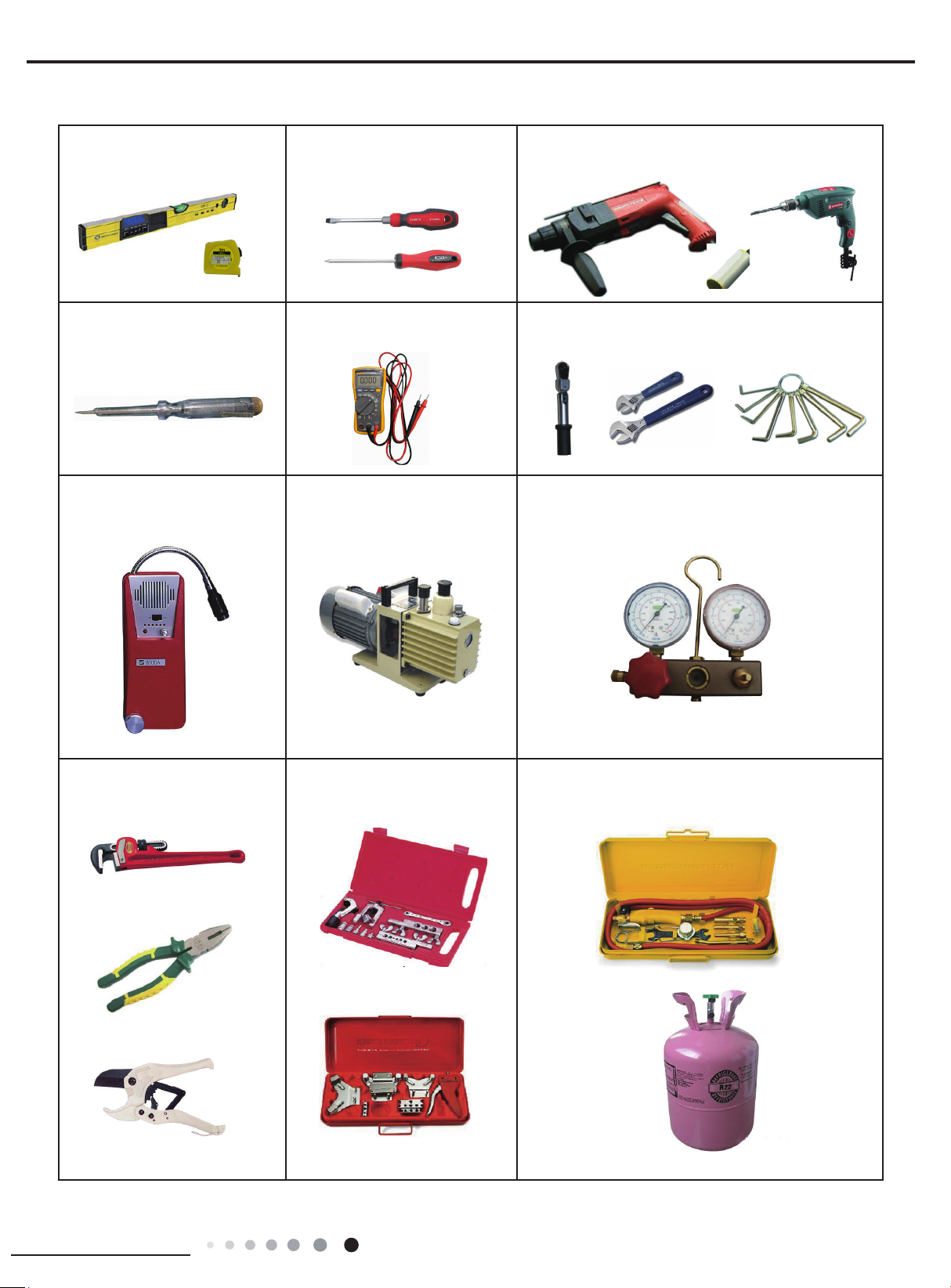
Main Tools for Installation and Maintenance
1. Level meter, measuring tape
4. Electroprobe
7. Electronic leakage detector
2. Screw driver
5. Universal meter
8. Vacuum pump
3. Impact drill, drill head, electric drill
6. Torque wrench, open-end wrench, inner
hexagon spanner
9. Pressure meter
10. Pipe pliers, pipe cutter
11. Pipe expander, pipe bender
12. Soldering appliance, refrigerant container
Installation and Maintenance
25
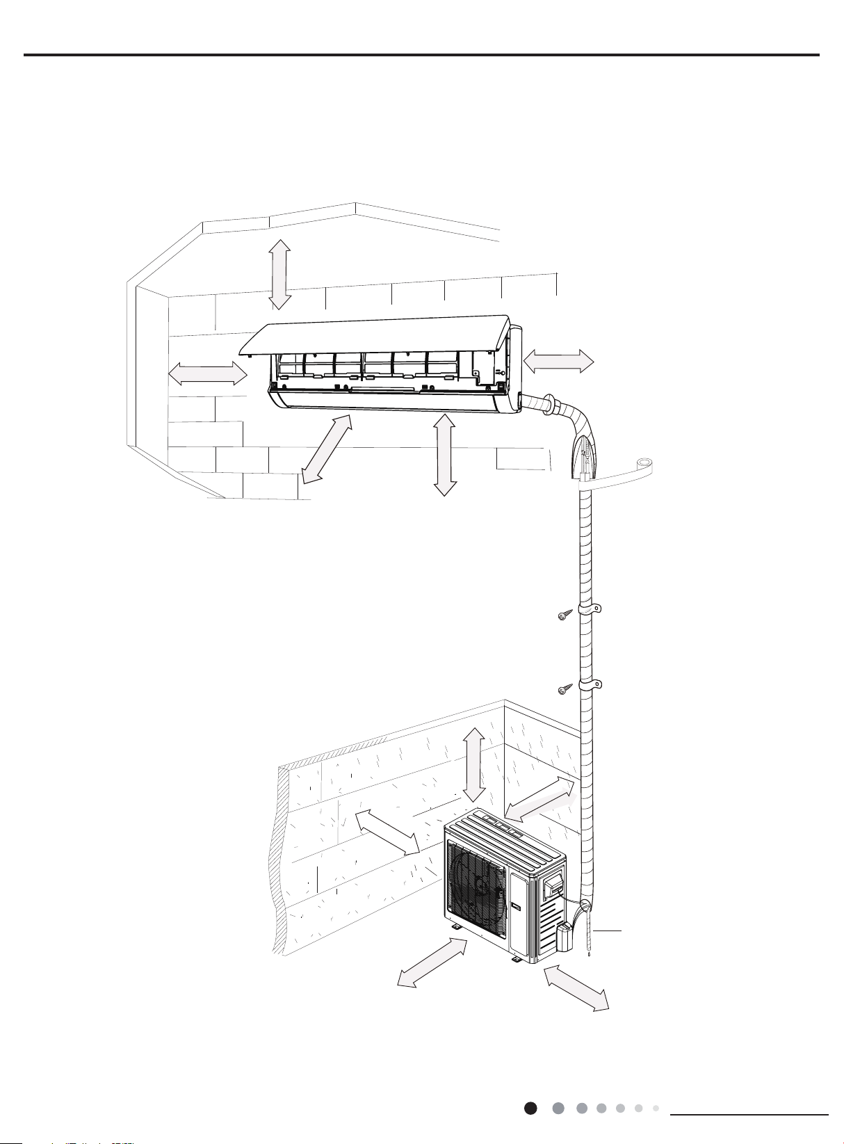
8. Installation
Drainage pipe
8.1 Installation Dimension Diagram
At least 5 7/8 inch
Space to the ceiling
Space to the wall
At least 5 7/8 inch
Service Manual
Space to the wall
At least 5 7/8 inch
roolf eht ot ecapS
At least 118 inch
Space to the obstruction
Space to the wall
At least 11 7/8 inch
At least 98 7/16 inch
Space to the obstruction
At least 19 11/16 inch
Space to the obstruction
At least 11
7/8
inch
26
Space to the obstructio
At least 78 3/4 inch
Space to the obstruction
At least 19 11/16 inch
Installation and Maintenance
Service Manual
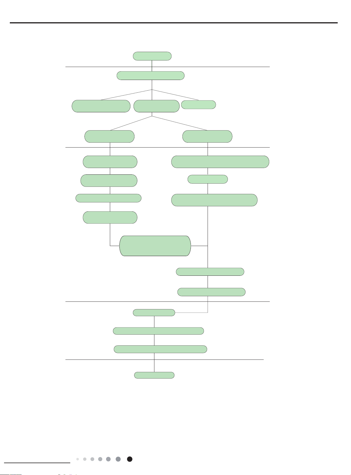
.
Installation procedures
Start installation
Preparation before installation
Read the requirements
for electric connection
Select indoor unit
installation location
Install wall-mounting
frame, drill wall holes
Connect pipes of indoor
unit and drainage pipe
Connect wires of indoor unit
Bind up pipes and
hang the indoor unit
Make the bound pipes pass
through the wall hole and then
connect outdoor unit
select installation
location
Prepare tools
Select outdoor unit
installation location
Install the support of outdoor unit
(select it according to the actual situation)
Fix outdoor unit
Install drainage joint of outdoor unit
(only for cooling and heating unit)
Connect pipes of outdoor unit
Connect wires of outdoor unit
Neaten the pipes
Vacuum pumping and leakage detection
Check after installation and test operation
Finish installation
Note: this flow is only for reference; please find the more detailed installation steps in this section
Installation and Maintenance
27
 Loading...