

Gree GWH12AB-D3DNA1B, GWH24AB-D3DNA1B, GWH12AB-A3DNA1B, GWH18AB-D3DNA1B, GWC09AB-D3DNA2D Owner's Manual
...
HIGH-WALL DUCTLESS
AIR CONDITIONING &
HEATING SYSTEM
OWNER’S MANUAL
Models:
GWH09AB-A3DNA1B
GWH12AB-A3DNA1B
GWH12AB-D3DNA1B
GWH18AB-D3DNA1B
GWH24AB-D3DNA1B
Thank you for selecting GREE evo High Wall
Ductless Air Conditioner and Heating System.
Please read this manual carefully before operation
and keep it for further reference.
For more information, please visit our website at
www.greecooling.com.
Table of Contents
Notices for operation................................................3
Typical operation........................................................5
Identifying major components.................................6
Wireless remote control operation..........................7
Emergency operation..............................................10
Cleaning and caring for your unit............................11
Troubleshooting......................................................12
NOTE: Figures in this manual may differ from the appearance of the actual unit. Refer to the system itself or contact a
qualifi ed service professional for further information.
Recognize safety information. This is the safety-alert symbol . When you see this symbol on the unit and in instructions
or manuals, be alert to the potential for personal injury. Understand these signal words: DANGER, WARNING, and
CAUTION. These words are used with the safety-alert symbol. DANGER identifi es the most serious hazards which will
result in severe personal injury or death.
WARNING signifi es hazards which could result in personal injury or death.
CAUTION is used to identify unsafe practices which may result in minor personal injury or product and property
damage.
NOTE is used to highlight suggestions which will result in enhanced installation, reliability, or operation.
Installation service..................................................15
Installation dimension diagram..............................16
Installing the indoor unit........................................17
Installing the outdoor unit......................................19
After installation and testing....................................20
Circuit diagrams......................................................20
Warranty...................................................................22
2
NOTICES FOR OPERATION
IMPORTANT OPERATING INFORMATION
PLEASE READ CAREFULLY BEFORE OPERATING THE UNIT.
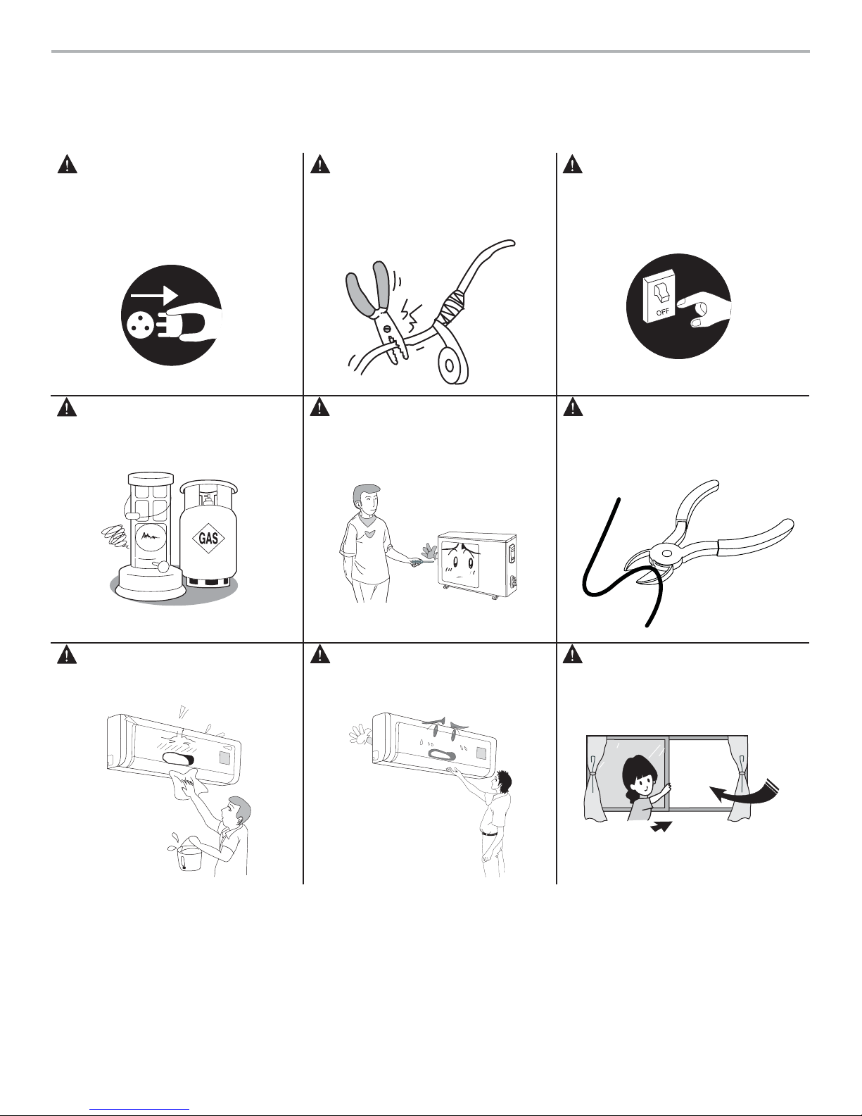
WARNING
Disconnect unit from power source
when it will not be in use for long
periods of time. Dust can accumulate
in the unit, which could be a fi re
hazard.
WARNING
Keep combustible materials away from
the unit.
WARNING
Do not splice the power cord or use
an extension cord. Overheating can
occur, causing a fi re hazard.
WARNING
Do not attempt to install, relocate or
repair the unit yourself. Contact a
qualifi ed service professional.
WARNING
If you smell or see smoke, turn unit off
and immediately contact a qualifi ed
service professional.
WARNING
Do not cut or damage power and/or
controls wires. In case of damage,
immediately contact a qualifi ed service
professional.
WARNING
Keep away from water. Do not clean
unit with water. This can cause electric
shock.
CAUTION
Do not insert your hands or any other
device into the air intake or outlet
vents.
NOTE
Keep windows and doors closed while
operating unit to save on electricity
cost.
3
NOTICES FOR OPERATION
IMPORTANT OPERATING INFORMATION
PLEASE READ CAREFULLY BEFORE OPERATING THE UNIT.
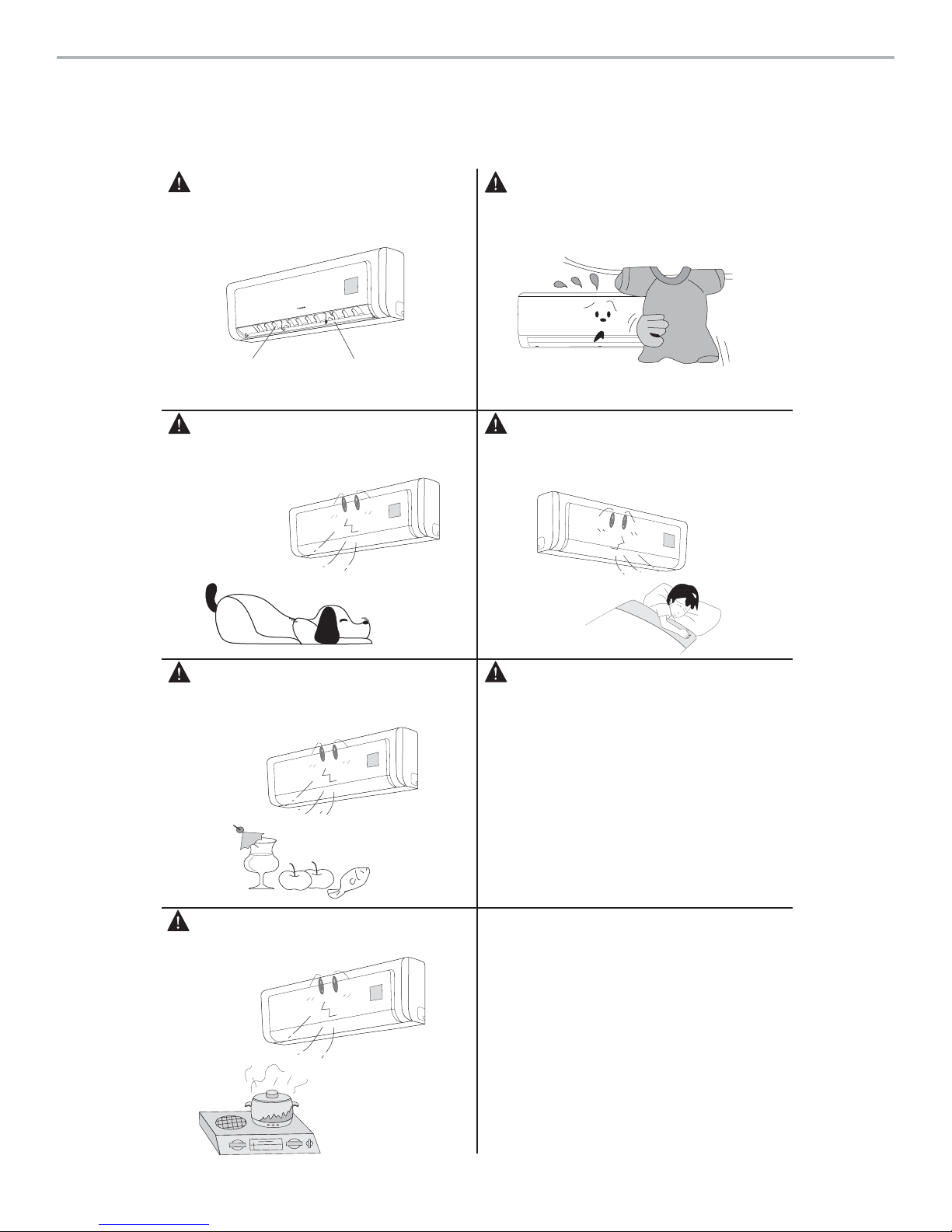
NOTE
Adjust vertical or lateral airfl ow using the
remote control.
Swing louver
NOTE
Do not direct the air toward animals or
plants.
Guide louver
NOTE
Do not block air intake or outlet vents on
either indoor or outdoor components. Doing
so may cause a malfunction of the unit.
NOTE
Do not allow cold air to directly blow on any
person for a prolonged time. This can cause
discomfort and worsen health problems.
NOTE
Do not use the unit to chill drinks,
preserving food or drying clothes.
NOTE
Keep space heaters and cooking units
away from air conditioner.
NOTE
After the unit has been professionally
installed, choose a thermostat setting that
is comfortable for all household members.
Do not repeatedly or rapidly turn the unit on
and off as this can cause malfunctions.
4

TYPICAL OPERATION
How your EVO unit works in cooling
In cooling mode, your EVO indoor unit will absorb heat from
the room, then the EVO outdoor unit will discharge the heat
to the outdoors. The EVO’s cooling capacity decreases
as the outdoor temperature increases. This causes the
EVO to work harder and longer to hold the selected room
temperature. Your evo unit will operate in cooling down to
41°F (5°C)
Indoor Coil Freeze Protection
• Frost may form on the indoor coil during cooling
operations when the outdoor temperature below 50°F
(10°C). Prolong operation may cause ice to form on the
indoor coil and block airfl ow. If the EVO indoor unit
microcomputer detects ice on the indoor coil it will stop the
compressor to defrost the coil and protect the unit.
How your EVO unit works in heating
In heating mode, your EVO outdoor unit will absorb heat
from the outdoor ambient, then the EVO indoor unit will
discharge the heat to the room. The EVO’s heating capacity
decreases as the outdoor temperature decreases. Your evo
unit will heat down to 5°F (-15°C).
During extreme cold outdoor temperatures, you may need
an additional heating source to supplement the EVO
heating output.
Defrost Function
• In heating mode, frost may form on the outdoor coil during
humid and low outdoor temperature conditions. Prolong
operation may cause ice to form on the outdoor coil and
block airflow. This will reduce the EVO’s heating capacity.
If the EVO microcomputer detects ice on the outdoor coil,
it will switch automatically to defrost mode to melt the ice
and clear the coil. During defrost mode, heating will be
discontinued and the EVO indoor unit will flash the Defrost
indicator. The compressor will continue to run while
indoor and outdoor fans will stop. It is normal to see steam
or vapor coming from the outdoor unit during defrost
mode. Defrost mode will terminate 12 minutes after
initiation of defrost cycle or when the outdoor coil
temperature is 50°F (10°C) or greater.
5
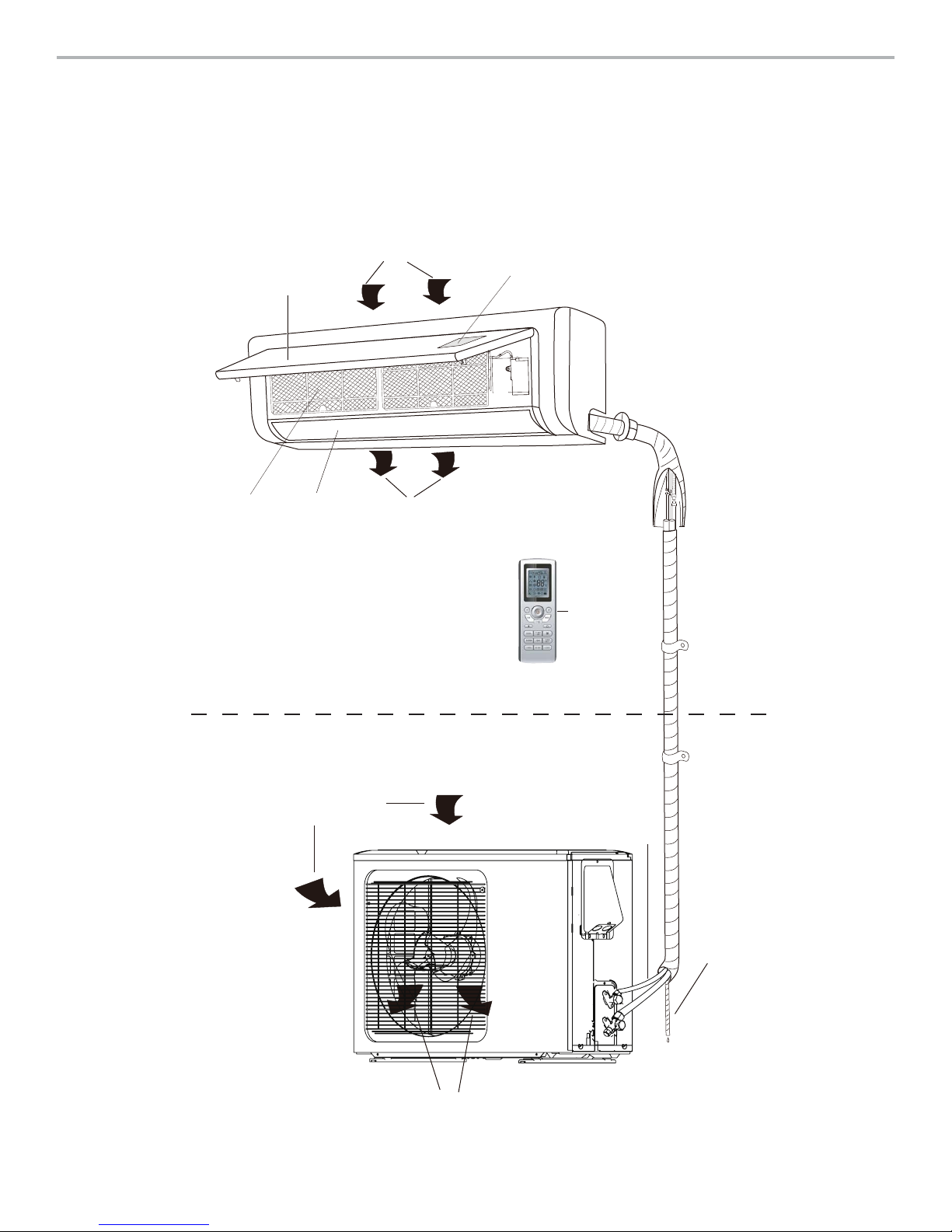
IDENTIFYING MAJOR COMPONENTS
Indoor unit
Air in
Remote receiver sensor
Front panel
Filter
Swing
louvers
Outdoor unit
Air in
Discharge
air
Remote
control
Refrigerate lines
and control wires
Condesate
drainage
pipe
6
Discharge
air
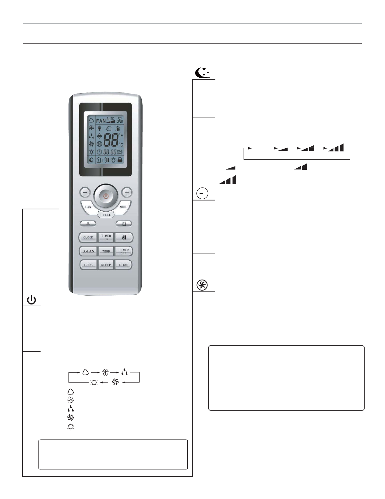
WIRELESS REMOTE CONTROL OPERATION
Names and Functions of Remote Control Buttons
Remote
Control
Signal Transmitter
FAN
LIGHT
SLEEP button
Press this button to select SLEEP ON or SLEEP OFF.
This function must be set after the unit is powered on.
It will not function under AUTO or FAN modes.
FAN button
Select Low, Medium or High in Auto mode for default
fan speed. In DRY mode, only low fan speed can be
selected.
AUTO
Low fan
Medium fan
High fan
CLOCK button
Press the button, and clock icon will fl ash. Within
5 seconds, set the time by pressing + or – buttons to
set hours and minutes. Press button again to save
time setting. Note that this is the current time, not the
timer setting.
LIGHT button
Press the LIGHT button and the indoor unit display
turns ON. Press again, the indoor unit display turns
OFF.
ON/OFF button
Press once to turn on unit. Press again to turn off
unit. Using the ON/OFF function will cancel TIMER
and SLEEP functions, but preset times will not be
affected.
MODE
MODE button
Set AUTO, COOL, DRY, FAN, or HEAT sequentially.
In Auto Mode, room temperature is not displayed.
AUTO
COOL
DRY
FAN
HEAT
(Only for cooling and heating unit.)
NOTE: On power up, unit will default to AUTO
Mode. Initial room setting is 77°F (25°C), except in
HEAT Mode the initial setting is 82°F (28°C).
TURBO button
In COOL or HEAT mode, use this button to turn
TURBO function on or off. The TURBO icon will
appear in the display when the function is on. When
changing modes or fan speeds, the function will be
canceled.
NOTE: Be sure there are no obstructions between
remote control and the EVO Indoor unit ( receiver
sensor)
• Do not drop or throw the remote control.
• Do not submerge remote control in water.
• Do not leave in direct sunlight.
• Do not leave near heat source.
7
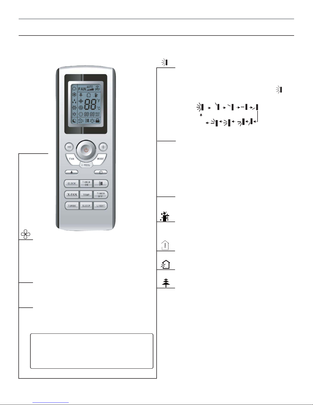
WIRELESS REMOTE CONTROL OPERATION
Names and Functions of Remote Control Buttons
NOTE: Not every unit has each of the functions described below. If your unit does not come equipped with a certain
function, the button will be inactive.
TIMER
Remote
Control
TIMER
SWING UP and DOWN BUTTON
Use this function to control direction of air circulation.
Select from fi ve louver positions available by pressing
the button. When the guide louver begins to swing up
or down, it turns off the SWING function and will
appear as the louver position is readjusting.
OFF
ON
TIMER ON button
When TIMER function is activated, the (clock icon)
will blink and numerical display becomes the timer
readout. Press the + or – button to adjust time. Every
press of the + or – keys adjusts time by 1 minute.
Within 5 seconds of setting the timer, press the
TIMER ON button to set the timer. Please check the
clock setting for accuracy after setting timer.
TIMER OFF button
OFF
To cancel TIMER settings, press TIMER OFF button.
Clock icon will blink, and settings will be canceled.
X-FAN button
Pressing the X-FAN button in COOL or DRY mode
will keep the fan running for 10 minutes to dry the
indoor unit. After drying, X-FAN OFF is defaulted.
This function is not available in AUTO FAN or HEAT
modes.
-
- Button
Use this button to decrease temperature in HEAT or
COOL modes. Press button for 2 seconds to activate.
+
+ Button
Use to increase temperature settings in HEAT or
COOL mode.
NOTE: In heat, cool, and dry mode, the room
temperature setting will be displayed.
In AUTO mode, the temperature display is off and
the + and - Buttons are not used.
I FEEL button
Press this button to activate I FEEL. When I FEEL
is active, the evo unit will use the room temperature
measured by the remote control.
TEMP button
This function not available.
Air button
This function not available.
Health button
This function not available.
8
 Loading...