


OWNER’S MANUAL
Thank you for choosing our product. Please read this owner’s manual carefully
before operating the unit and keep it for future reference.
0
0708-11/01/2015
© Copyright, GREE Canada, 2015
GWC09QB-D3DNA6E
GWH09QB-D3DNA6E
GWC12QC-D3DNA6E
GWH12QC-D3DNA6E
GWC18QD-D3DNA6E
GWH18QD-D3DNA6E
GWC24QE-D3DNA6E
GWH24QE-D3DNA6E

~
GWC09QB-D3DNA6E
GWH09QB-D3DNA6E
GWC12QC-D3DNA6E
GWH12QC-D3DNA6E
GWC18QD-D3DNA6E
GWH18QD-D3DNA6E
GWC24QE-D3DNA6E
GWH24QE-D3DNA6E

Content
Operation Notices
Precautions ..............................................................................1
Parts Name ..............................................................................5
Indoor Unit Screen Display ......................................................6
Remote Control
Buttons on remote control ........................................................7
Introduction for icons on remote control ..................................8
Operation of remote control ......................................................9
Special functions ......................................................................12
Replacement of batteries in remote controller ........................13
Emergency operation ..............................................................14
Maintenance
Clean and Maintenance ..........................................................15
Malfunction
Malfunction analysis ................................................................17
Installation Notice
Installation dimension diagram ................................................21
Tools for installation ................................................................22
Selection of installation location ..............................................22
Requirements for electric connection ......................................23
Installation
Installation of indoor unit ..........................................................24
Installation of outdoor unit ........................................................29
Vacuum pumping ....................................................................32
Leakage detection ....................................................................32
Check after installation ............................................................33
Test and operation
Test operation ..........................................................................33
Attachment
Configuration of connection pipe ............................................34
Pipe expanding method ..........................................................36
Wired Controller ......................................................................37
This appliance is not intended for use by persons (including children) with
reduced physical, sensory or mental capabilities, or lack of experience and
knowledge, unless they have been given supervision or instruction
concerning use of the appliance by a person responsible for their safety.
Children should be supervised to ensure that they do not play with the
appliance.
ANGLAIS

Indicates a hazardous situation that, if not avoided, will
result in death or serious injury.
Indicates a hazardous situation that, if not avoided, could
result in death or serious injury.
Indicates a hazardous situation that, if not avoided, may
result in minor or moderate injury.
Indicates important but not hazard-related information,
used to indicate risk of property damage.
Indicates a hazard and it is assigned to the signal words
DANGER, WARNING or CAUTION.
DANGER
WARNING
CAUTION
NOTICE

1A
Precautions
WARNING
Operation and Maintenance
• This appliance can be used by children aged from 8 years and above
and persons with reduced physical, sensory or mental capabilities or
lack of experience and knowledge if they have been given supervision or instruction concerning use of the appliance in a safe
way and understand the hazards involved.
• Children shall not play with the appliance.
• Cleaning and user maintenance shall not be made by
children.
• Do not connect air conditioner to multi-purpose socket.
Otherwise, it may cause fire hazard.
• Do disconnect power supply when cleaning air
conditioner. Otherwise, it may cause electric shock.
• If the supply wire is damaged, it must be replaced by
the manufacturer, its service agent or similarly qualified
persons in order to avoid a hazard.
• Do not wash the air conditioner with water to avoid
electric shock.
• Do not spray water on indoor unit. It may cause electric
shock or malfunction.
• After removing the filter, do not touch fins to avoid injury.
• Do not use fire or hair dryer to dry the filter to avoid
deformation or fire hazard.

1B
Precautions
WARNING
Operation and Maintenance
• Maintenance must be performed by qualified professionals.
Otherwise, it may cause personal injury or damage.
• Do not repair air conditioner by yourself. It may cause electric shock
or damage. Please contact dealer when you need to repair air
conditioner.
• Do not extend fingers or objects into air inlet or air outlet. It may
cause personal injury or damage.
• Do not block air outlet or air inlet. It may cause malfunction.
• Do not spill water on the remote control, otherwise the remote
control may be broken.
• When below phenomenon occurs, please turn off air conditioner and
disconnect power immediately, and then contact the dealer or
qualified professionals for service.
• If the air conditioner operates under abnormal conditions, it may
cause malfunction, electric shock or fire hazard.
• When turning on or turning off the unit by emergency operation
switch, please press this switch with an insulating object other than
metal.
• Do not step on top panel of outdoor unit, or put heavy objects. It may
cause damage or personal injury.
• There’s abnormal sound during operation.
• Circuit break trips off frequently.
• Air conditioner gives off burning smell.
• Indoor unit is leaking.

2
Precautions
WARNING
Attachment
• Installation must be performed by qualified professionals.
Otherwise, it may cause personal injury or damage.
• Must follow the electric safety regulations when installing the unit.
• According to the local safety regulations, use qualified power supply
circuit and circuit break.
• Install a circuit breaker of adequate capacity only used for the
system; otherwise, it may cause malfunction.
• An all-pole disconnection switch having a contact separation of at
least 3mm in all poles should be connected in fixed wiring.
• Air Conditioner should be properly grounded. Incorrect grounding
may cause electric shock.
• Make sure the power supply matches with the requirement of air
conditioner.Unstable power supply or incorrect wiring may cause mal
function of the unit, electric shock or fire hazard
• Properly connect the live wire, neutral wire and grounding wire.
• Be sure to cut off the power supply before proceeding any work
related to electricity and safety.
3
Precautions
WARNING
• Do not put through the power before finishing installation.
• If the supply cord is damaged, it must be replaced by the manufacturer, its service agent or similarly qualified persons in order to avoid a
hazard.
• The temperature of refrigerant circuit will be high, please keep the
interconnection cable away from the copper tube.
• The appliance shall be installed in accordance with national wiring
regulations.
• Installation must be performed in accordance with the requirement of
NEC and CEC by authorized personnel only.
• The air conditioner is a first class electric appliance. It must be
properly grounded with specialized grounding device by a professional. Please make sure it is always grounded effectively, otherwise it
may cause electric shock.
• The yellow-green wire in the air conditioner is the grounding wire,
which can't be used for other purposes.
• The grounding resistance should comply with national electric safety
regulations.
• All wires of indoor unit and outdoor unit should be connected by a
professional.
• If the length of power connection wire is insufficient, please contact
the supplier for a new one. Do not extend the wire yourself.

4
Precautions
WARNING
• If you need to relocate the air conditioner to another place, only a
qualified person can perform the work. Otherwise, it may cause
personal injury or damage.
• Select a location which is out of reach for children and far away from
animals or plants.If it is unavoidable, please add the fence around the
outdoor unit for safety purpose.
• The indoor unit should be installed close to the wall.
• Instructions for installation and use of this product are provided by
the manufacturer.
Working temperature range
Indoor side DB/WB(°C ) Outdoor side DB/WB(°C )
Maximum cooling
NOTICE :
• The operating temperature range (outdoor temperature) for cooling
only unit is -18 (-0.4°F)~46.1℃ (115°F) ; for heat pump unit is
-20℃ (-4°F)~46.1℃ (115°F).
26.7/19.4 (80/66.9) 46.1/23.9 (115/75)
26.7/- (80/-) 23.9/18.3 (75/64.9)
Maximum cooling
5
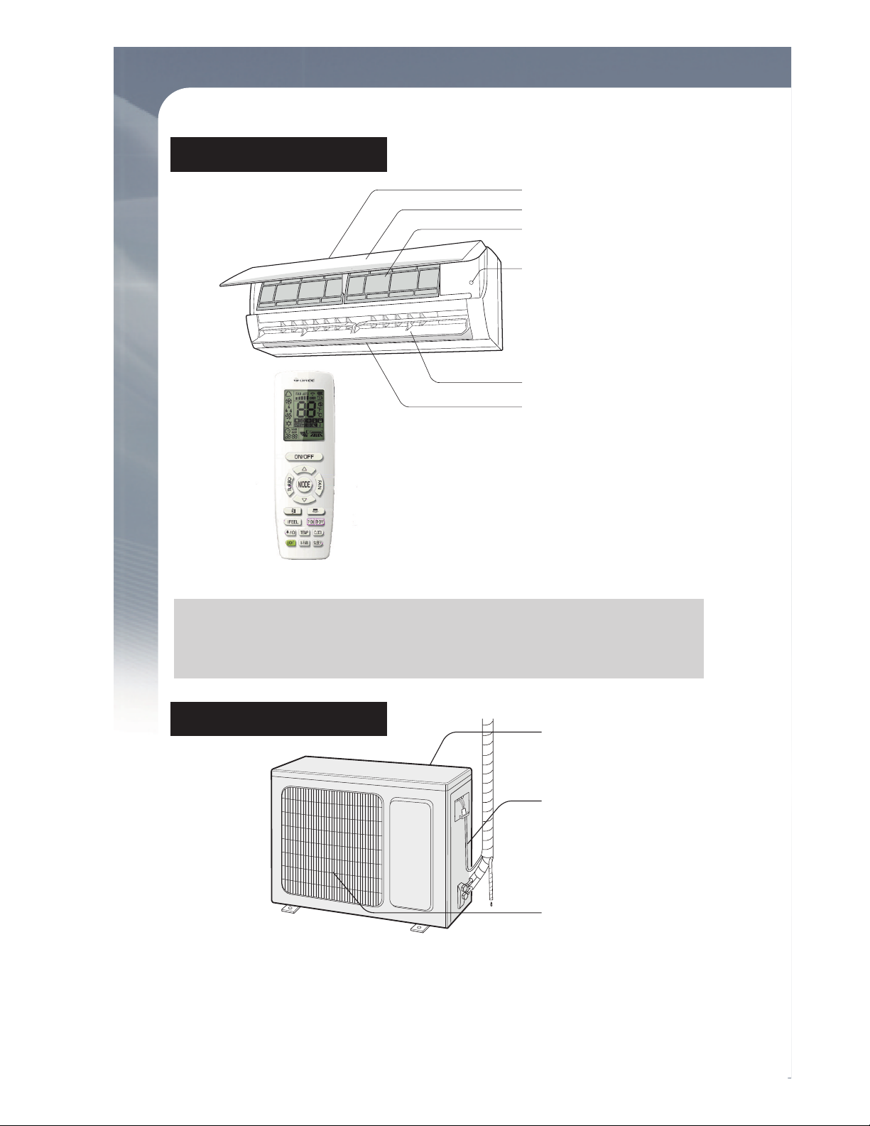
Parts Name
Panel
Filter
Air outlet
Air inlet
Horizontal louver
AVIS :
(Display content or position may be different from above
graphics, please refer to actual products)
Indoor Unit
Outdoor Unit
Aux.button
Remote control
NOTICE :
Actual product may be different from above graphics, please
refer to actual products.
Air inlet
Connection wire
Air outlet
6
W
R
G
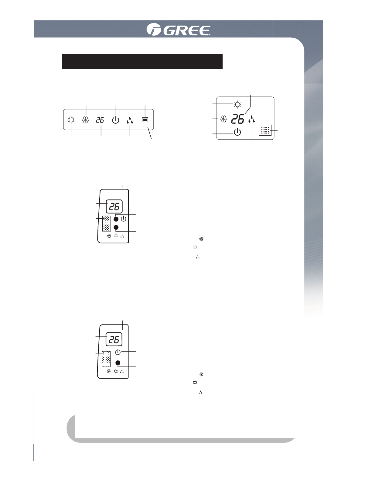
Indoor Unit Screen Display
For some model: For some model:
For some model:
cooling
indicator
power
indicator
receiver
window
receiver
window
heating
indicator
cooling
indicator
power
indicator
display
display
(only for heating mode)
receiver
window
drying
indicator
heating
indicator
temp.
indicator
temp.
indicator
Power LED color
indicator:
Green status ON:
Red status OFF:
Mode LED color indicator:
White W Cool Mode
Red R Heat Mode
Green G Dry Mode
drying
indicator
display
Display and icons position may vary with models
W
R
G
W
R
O
For some model:
receiver
window
display
(only for heating mode)
temp.
indicator
Power LED color indicator:
Green-status-ON.
Red -status-OFF.
Mode LED color indicator:
White W Cool Mode
Red R Heat Mode
Orange O Dry Mode
W
R
G
Display content or position may be different from above graphics,
please refer to actual products.
7
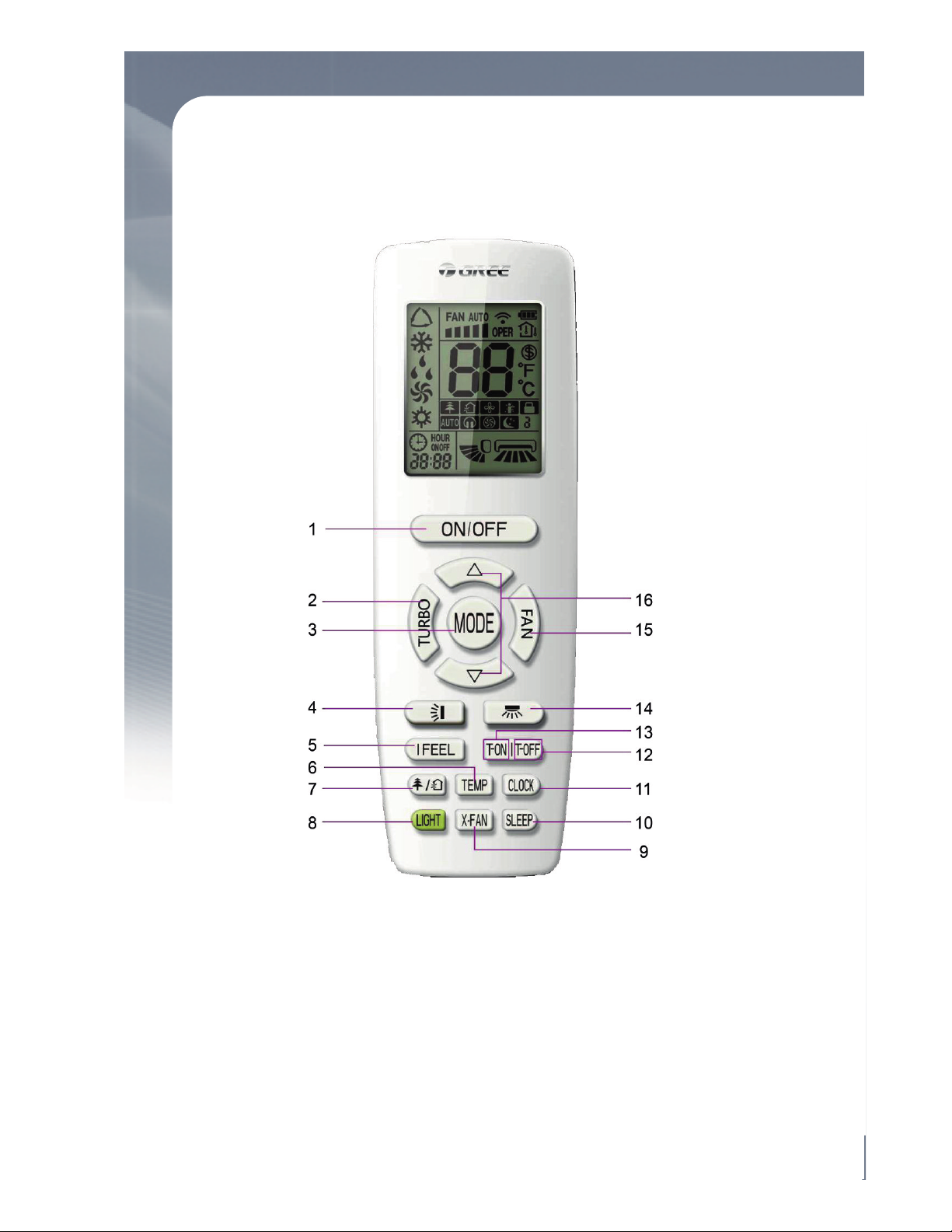
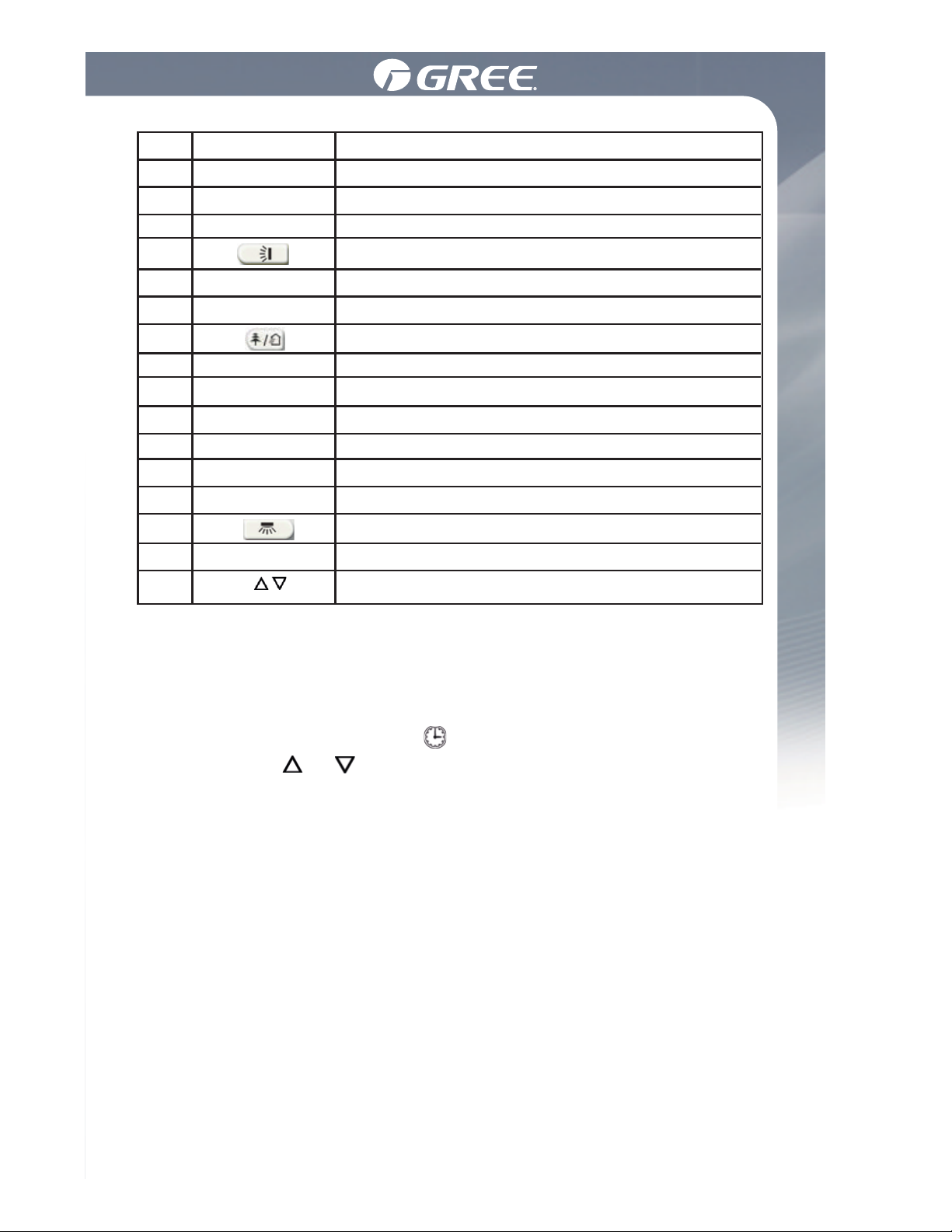
Button name and function introduction
Remote Control:
8
Using the Remote Control
1.2 Preparation before operation
Using the Remote Control
When using the remote control for the first time or after replacing the
batteries, please set the current time as per the following steps:
(1). Pressing CLOCK button, is blinking.
(2). Pressing or button, the clock time will increase or
decrease rapidly.
(3). Press CLOCK button again to confirm the time and return to
display current time.
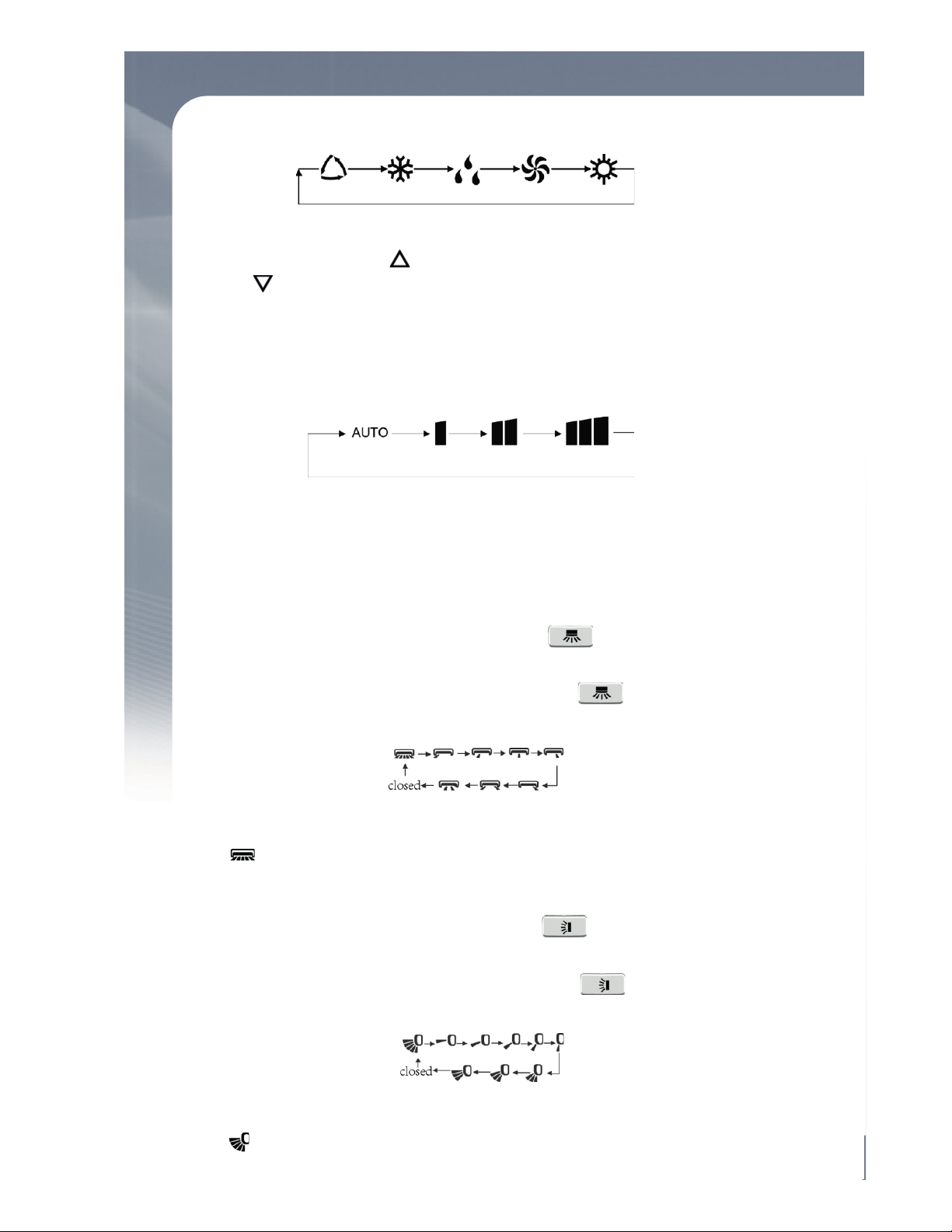
(1). Selecting operation mode
In unit on status, press MODE button to select operation
mode in following sequence:
No.
1
2
3
4
5
6
7
8
9
10
11
12
13
14
15
16
Button name
ON/OFF
TURBO
MODE
I FEEL
TEMP
LIGHT
X-FAN
SLEEP
CLOCK
TOFF
TON
FAN
Function
Turn on or turn off the unit
Set turbo function
Set operation mode
Set up&down swing status
Set I FEEL function
Switch temperature displaying type on the unitʼs display
Set health function and air function
Set light function
Set X-FAN function
Set sleep function
Set clock of the system
Set timer off function
Set timer on function
Set left&right swing status
Set fan speed
Set temperature and time
/
o
9
Using the Remote Control
In unit on status, press button to increase setting temperature and press
button to decrease setting temperature. The range of temperature is from
16℃ to 30℃.
Note: Under auto mode, you cannot change the temperature.
Note: operate continuously left&right swing in 2 seconds, swing status
will change according to above-mentioned order, or switch closed status
and status.
Note: operate continuously left&right swing in 2 seconds, swing status
will change according to above-mentioned order, or switch closed status
and status;
In unit on status, press FAN button to adjust fan speed in following
sequence:
Note:
(2). Setting temperature
(3). Adjusting fan speed
① . When operation mode changes, fan speed is memorized;
②. Under dry mode, fan speed is low and can not be adjusted.
(4). Setting swing function
◆ Setting left&right swing
1). Under simple swing status, press button to adjust
left&right swing status;
2). Under fixed-angle swing status, press button to adjust
left&right swing angle circularly as below:
◆ Setting up&down swing
1). Under simple swing status, press button to adjust
up&down swing status;
2). Under fixed-angle swing status, press button to adjust
up&down swing angle circularly as below:
o
Auto Low Medium High
Auto Cool Dry Fan Heat

10
Using the Remote Control
Under cool or heat mode, press TURBO button to set turbo function.
When is displayed, turbo function is on. When it is not displayed,
turbo function is off.
When turbo function is on, the unit operates in super high speed to
achieve quick cooling or heating. When turbo function is off, the unit
operates in setting fan speed.
The light on the receiver light board will display present operation
status. If you want to turn off the light, please press LIGHT button.
Press this button again to turn on the light.
In unit on status, receiver light board is defaulted to display setting
temperature. Press TEMP button to view indoor or outdoor ambient
temperature.
Health function is available when the unit is equipped with anion
generator. When health function is on, the anion generator will start
operation, absorbing the dusts and killing the bacteria in the room.
(5). Setting turbo function
(6). Setting light function
(7). Viewing ambient temperature
(8). Setting X-FAN function
In cool or dry mode, press X-FAN button to set X-FAN function.
When is displayed, X-FAN function is on. When you cancel
the function by pressing again the button, the icon will disappear.
When X-FAN function is on, after you have pressed the ON/OFF
(marche/arrêt) button to stop the unit, the fan will keep un running for about 2 min. to blow away the water on the evaporator,
thus eliminating risk of mildew.
(9). Setting health function
In unit on status, press button to set health function.
When is displayed, health function is on.
When you cancel the HEALTH mode by pressing again on
the button, the icon will disappear.
When is displayed, the set in temperature is displayed.
When is displayed, the indoor ambient temperature is
displayed.
When is displayed, the current outdoor temperature is
displayed.
Note: set in temperature is always displayed in Remote Controller.

11
Userʼs Manual of Remote Control
Press button until is displayed, then air function is turned on.
Press button until is disappeared, then air function is turned off.
When the indoor unit is connected with fresh air valve, air function setting can control the connection of fresh air valve, which can control the
fresh air volume and improve the air quality inside the room.
In unit on status, press I FEEL button to turn on or turn off I FEEL function.
When is displayed, I FEEL function is on.
When is not displayed, I FEEL function is off.
When I FEEL function is turned on, the unit will adjust temperature according to the temperature detected by the remote controller to achieve the
best air-conditioning effect. In this case, you should place the remote
controller within the valid receiving range.
You can set the operation time of unit as you need. You can also set timer on
and timer off in combination.
Before setting, check if the time of the system is the same as the current time.
If not, please set the time according to current time.
In unit on status, press SLEEP button to turn on or turn off sleep function.
◆ When is displayed, sleep function is on.
◆ When is not displayed, sleep function is off.
① . Sleep function can not be set in auto and fan mode;
②.
When turning off the unit or switching mode, sleep function is cancelled;
1). Setting timer off
① . Pressing TOFF button, “OFF” is blinking and time displaying zone
displays the timer time of last setting.
②. Press or button to adjust the timer time.
③. Press TOFF button again to confirm setting. OFF is displayed and
time displaying zone resumes to display current time.
Notes:
(10). Setting air function
(11). Setting sleep function
(12). Setting I FEEL function
(13). Setting timer

12
Using the Remote control
1.4 Special function buttons
④. Press TOFF button again to cancel timer and OFF is not displayed.
2). Setting timer on
① . Pressing TON button, “ON” is blinking and time displaying zone
displays the timer time of last setting.
②. Press or button to adjust the timer time.
③. Press TON button again to confirm setting. ON is displayed and time
displaying zone resumes to display current time.
④. Press TON button again to cancel timer and ON is not displayed.
(1). Setting child lock
Press and buttons simultaneously to lock the buttons on
remote control and is displayed .
Press and buttons simultaneously again to unlock the buttons
on remote control and is not displayed .
If the buttons are locked, blinks 3 times when pressing the button
and any operation on the button is invalid.
(2). Switching temperature scale
In unit off status, press MODE button and button simultaneously
to switch temperature scale between ℃ and ℉.
(3). Setting energy-saving function
In unit on status and under cool mode, press CLOCK and TEMP
buttons simultaneously to enter energy-saving mode.
◆ When is displayed, energy-saving function is on.
◆ When is not displayed, energy-saving function is off.
If you want to turn off the energy-saving function, press again on
CLOCK and TEMP buttons and is no longer displayed.
Note: energy-saving function is only available in cooling mode and it will
be exited when switching mode or setting sleep function.
(4). Absence function
In unit on status and under heat mode, press CLOCK and TEMP buttons
simultaneously to enter absence function. Temperature displaying zone
displays 8 and is displayed.
Press CLOCK and TEMP buttons simultaneously again to exit absence
function. Temperature displaying zone resumes previous display and is
not displayed.

2
5
10
Fig.20
25
10
Fig.20
13
Using the Remote Control
1.5 Replacing batteries in remote control
(1). Lift the cover along the direction of arrow (as shown in Fig 1① ).
(2). Take out the original batteries (as shown in Fig 1②).
(3). Place two 7# (AAA 1.5V) dry batteries, and make sure the position of
+ and - terminals is correct (as shown in Fig 2③).
(4). Reinstall the cover (as shown in Fig 2④).
In winter, absence function can keep the indoor ambient temperature
above 0℃ to avoid freezing.
Note: Absence function is only available in heating mode and it will be
exited when switching mode or setting sleep function.
Notes:
① . The remote controller should be placed 1m away from the TV set
or stereo sound sets.
②. The operation of remote controller should be performed within its
receiving range.
③. If you need to control the main unit, please point the remote
controller at the signal receiving window of the main unit to improve
the receiving sensibility of main unit.
④. When the remote controller is sending signal, “ ” icon will be blin-
king for 1 second. When the main unit receives valid remote control
signal, it will give out a sound.
⑤. If the remote controller does not operate normally, please take the
batteries out and reinsert them after 30 seconds. If it still can't
operate properly, replace the batteries.
⑥. When replacing the batteries, do not use old or different types of
batteries, otherwise, it may cause malfunction.
⑦. When you wonʼt use the remote controller for a long time, please
take out the batteries.
Fig.1 Fig.2
 Loading...