

Gree GWC09KF-K3DNA5A, GWC12KF-K3DNA5A, GWH09KF-K3DNA5A, GWH12KF-K3DNA5A Service Manual
GREE ELECTRIC APPLIANCES,INC.OF ZHUHAI
Service Manual
MODEL:
GWC09KF-K3DNA5A
GWH09KF-K3DNA5A
GWC12KF-K3DNA5A
GWH12KF-K3DNA5A
(Refrigerant R-410A)
1
Summary and features
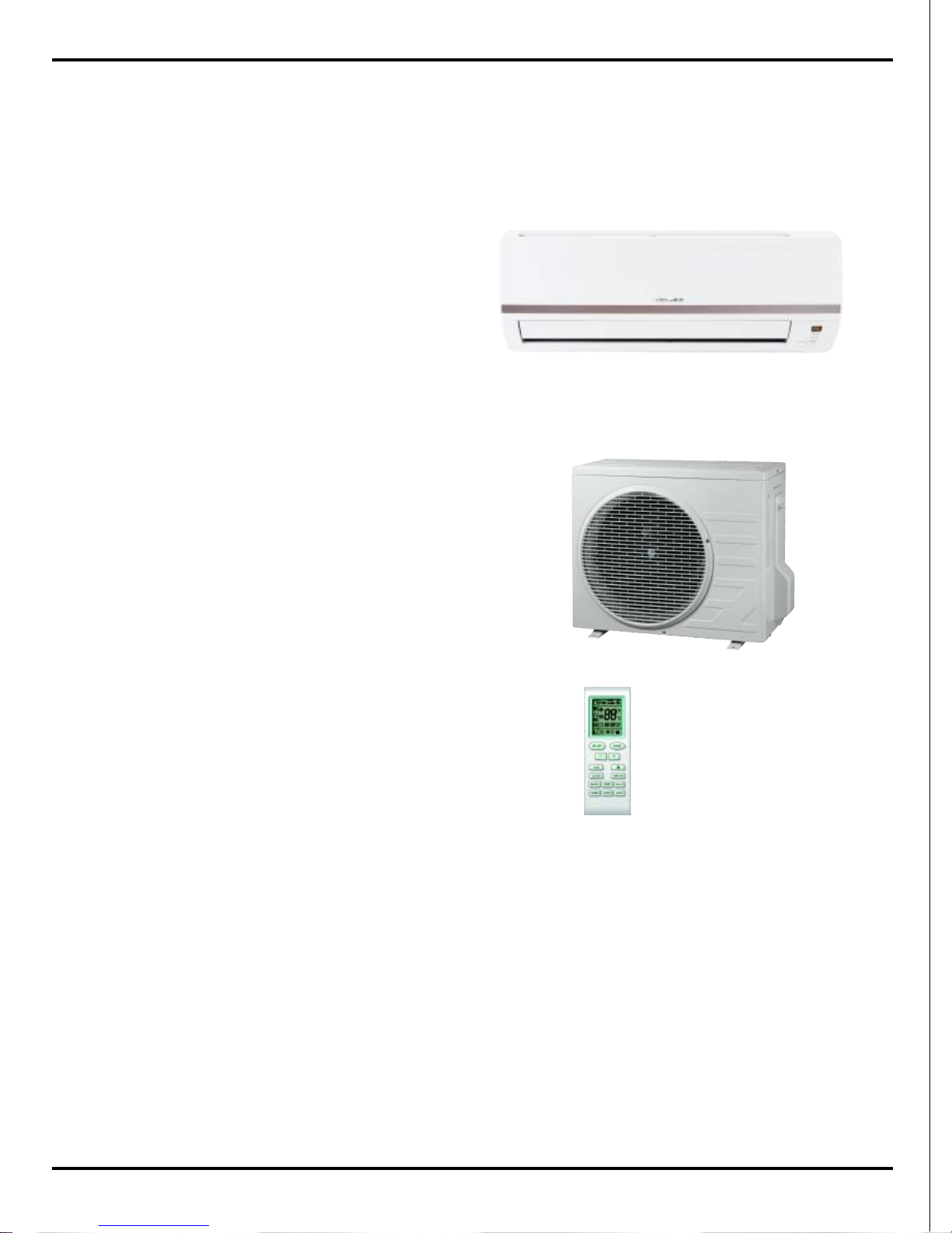
Indoor Unit
GWC09KF-K3DNA5A/I
GWH09KF-K3DNA5A/I
GWC12KF-K3DNA5A/I
GWH12KF-K3DNA5A/I
Outdoor Unit
GWC09KF-K3DNA5A/O (CB146W0050)
GWH09KF-K3DNA5A/O(CB146W0060 )
GWC12KF-K3DNA5A/O(CB146W0070 )
GWH12KF-K3DNA5A/O(CB146W0080 )
Remote control window
YB1F2
Summary and features

Table of Contents
Summary and features..................................................................... 1
Part 1 1.Safety Precautions.............................................................2
Part 2 SPECIFICATIONS...................................................................3
2.1 Unit Specifications.............................................................................................3
2.2 Operation Characteristic Curve...............................................................7
2.3 CapacityVariationRatio AccordingtoTemperature...................................7
2.4 Operation Date........................................................................................8
2.5 Noise criteria curve tables for both models.............................................8
Part 3 Construction Views...............................................................9
3.1 Indoor Unit ..............................................................................................9
3.2 Outdoor Unit ............................................................................................9
Part 4 Refrigerant System Diagram...............................................10
Part 5 Schematic Diagram..............................................................11
5.1 ELECTRICAL DATA...............................................................................11
5.2 Electrical wiring ......................................................................................11
5.3 Printed Circuit Board ..............................................................................13
Part 4 Function and Control...........................................................18
6.1 Remote Control Operations.....................................................................18
6.2 Changing batteries and notices ...............................................................21
6.3 Unit indlcation section ..............................................................................21
6.4 Unit ON/OFF button .................................................................................21
6.5 DESCRIPTION OF EACH CONTROL OPERATION ...............................22
Error Detection of Temperature Sensor
6.6 .........................................................................................24
6.7 Frequency Control ...................................................................................24
6.8 3-minutes Standby ...................................................................................24
6.9 Compressor Protection Function .............................................................24
6.10 Discharge Pipe Control ..........................................................................25
6.11 Input Current Control .............................................................................25
6.12 Freeze-up Protection Control .................................................................25

Table of Contents
6.13 Heating Peak-cut Control ......................................................................26
6.14 Defrost Control ......................................................................................26
6.15 Fan Control ...........................................................................................27
Part 7 INSTALLATION MANUAL.....................................................28
7.1 Tools Required for Installation ................................................................28
7.2 Installation Position Selection ..................................................................26
7.3 INSTALLATION OF INDOOR UNIT .........................................................26
7.4 INSTALLATION OF OUTDOOR UNIT .....................................................32
7.5 Test Operation ..........................................................................................33
Part 8 EXPLODED VIEWS AND PARTS LIST....................................34
8.1 Exploded View .......................................................................................34
8.2 Parts Listt ................................................................................................37
Part 9 TROUBLESHOOTING.............................................................40
9.1 Precautions before Performing Inspection or Repair..............................40
9.2 Confirmation ............................................................................................40
9.3 Judgement by Flashing LED of Indoor/Outdoor Unit ...............................40
9.4 How to Check simply the main part ..........................................................42
9.5 2-way, 3-way Valve Appearance ..............................................................46
Part 10 Removal Procedure...........................................................53
10.1 Removal Procedure of Indoor Unit........................................................53
10.2 Removal Procedure of Outdoor Unit .....................................................67
2
1.Safety Precautions
Safety Precautions
Important!
This air conditioning system meets strict safety and
operating standards. As the installer or service person,
it is an important part of your job to install or service the
system so it operates safely and efficiently.
Follow each installation or repair step exactly as shown.
Observe all local, state, and national electrical codes.
Pay close attention to all warning and caution notices
given in this manual.
To prevent injury to the user or other people and
property damage, the following instructions must
be followed.
About the pictograms:
Erroneous handing gives a high possibility to induce serious results such as
death or heavy injury.
Erroneous handing may induce serious
injury depending on the situation.
Do not supply power to the unit until all wiring and tubing
are completed or reconnected and checked.
Highly dangerous electrical voltages are used in this
system. Carefully refer to the wiring diagram and these
instructions when wiring. Improper connections and inadequate grounding can cause accidental injury or death.
Ground the unit following local electrical codes.
Connect all wiring tightly. Loose wiring may cause overheating at connection points and a possible fire hazard.
All electric work must be performed by licensed technician,according to local regulations and the instructions given in this
manual.
There is risk of fire, electric shock, explosion, or injury.
Ask your dealer or specialized subcontractor for installation or
repair work.
Make sure the ceiling/wall is strong enough to hold the
unit’s weight. The outdoor unit shoukd be installed in a
location where air and noise emitted by the unit will not
disturb the neighbours.
Properly insulate any tubing run inside a room to prevent
"sweating" that can cause dripping and water damage to
walls and floors.
The outdoor unit must be installed on stable, level surface,
in a place where there is no accumulation of snow, leaves
or rubbish.
The unit should be installed according to the instructions
in order to minimize the risk of damage from earthquakes,
typhoons or strong winds.
When the refrigerant touches the fire elc., it was decomposed
and a poisonous gas is generated.
Use only the specified refrigerant to charge the regrigerant
circuit.
Do not mix it with any other refrigerant and do not allow air to
remain in the circuit.
Air enclosed in the circuit can cause high pressure resulting
in a rupture and other hazards.
After completing installation work, make sure that refrigerant gas has not leaked.
The limit density is made not to be exceeded even if the refrigerant leaks by any chance.
Turn the power off at the main power box (mains) before opening the unit to check or repair electrical parts and wiring.
Keep your fingers and clothing away from any moving parts.
Clean up the site after you finish, remembering to check that
no metal scraps or bits of wiring have been left inside the unit
being serviced.
The unit must be properly earth connected.
Caution
Warning
Warning
Caution
Never indtall on the place where a combustible gas might
leak. The gas may ignite or explode when the gas leaks and
collects in surround of the unit.
When the unit is installed at telecommunication centers or
hospitals, take a proper provision against noise.
When installing at a watery place, provide an electric leak
breaker.
Do not wash the unit with water.
Be very careful about unit transportation.The unit shoukd not
be carried by only one person if it is more than 20kg. It occasionally causes the damage of th unit and health to be impaired.
Do not touch the heat exchanger fins whth your bear hands.
Doing so may cut your hands.
Do not touch the compressor or refrigerant piping whithout
wearing glove on your hands. Touching directly such part can
cause a burn or frostbite as it becomes high or low temperature
according to the refrigerant state.
Do not operate the air conditioner without the air filter set
place. Dust may accumulate, and cause a failure.
At emergency (if you smell something burning), stop operation and turn the power source switch off.
3
2.SPECIFICATIONS
COOLING HEATING
High Hz 78 98
Standard Hz 53 72
Low Hz 15 24
High W / Bt u/h 3230 / 11000 4100 / 14000
Standard W / Bt u/h 2650 / 9000 3520 / 12000
Low W / B tu/h 450 / 1500 450 / 1500
High W 1350 1450
Standard W 800 950
Low W 200 200
W 1420 1550
A6.36.8
H
m
3
/h
M
m
3
/h
L
m
3
/h
l/h
W/W
Hr/min
Mr/min
Lr/min
W
μF
A
mm
mm
mm
mm
W
A
HdB (A)
MdB (A)
LdB (A)
HdB (A)
MdB (A)
LdB (A)
mm
mm
kg
610×294×24
8/11
38
48
770×283×201
844×342×261
24
40
34
30
MP24BA
1.5
PCB 3.15A
1.2
0.16
Cross flow fan – 1
φ92X594
Aluminum f i n-copper tube
7
2-1.4
8/11
GWH09KF -K3DNA5A
220-240V
~
520
0.8
3.3/3.7
A/A
GWH09KF -K3DNA5A/I
1100
10
770x283x201
844x342x261
24
40
34
1.5
PCB 3.15A
38
48
30
10
900
1.2
700
3.3
A/A
GWC09KF -K3DNA5A/I
1100
GWC09KF -K3DNA5A
220-240V
~
520
0.8
1420
6.3
800
2650 / 9000
450 / 1500
COOLING
Energy Class
EER / C.O. P
Speed
Fan Motor
Indoor unit
Model
Function
Rated Voltage
Rated Input
Frequency
(Inv erter di ffer ent Compressor
speed)
Total Capacity
(Inv erter di ffer ent Compressor
speed)
Power Input
(Inv erter di ffer ent Compressor
speed)
78
3230 / 11000
200
1350
53
15
Ai
r F
low Volume
Rated Cur r ent
Fuse (A)
Dimension (W×H×D) ( mm)
Fan
Evaporator
Swing
Motor
Coil lengt h (l)×height (H) ×
coil widt h ( L)
Output
Type-Piece
Dimension of Pack age (L×W × H)
Net Weight /Gr o ss Weight
Output
Capacitor
RLA
Diameter-Length
Pipe Diameter
Row-F in Gap
Sound P r essure Level
Sound P ower Level
2-1.4
610X294X24
MP24BA
0.16
Cross flow fan - 1
φ92X594
Aluminum f i n-copper tube
Model
370
280
370
280
900
700
Dehumidifying Volume
7
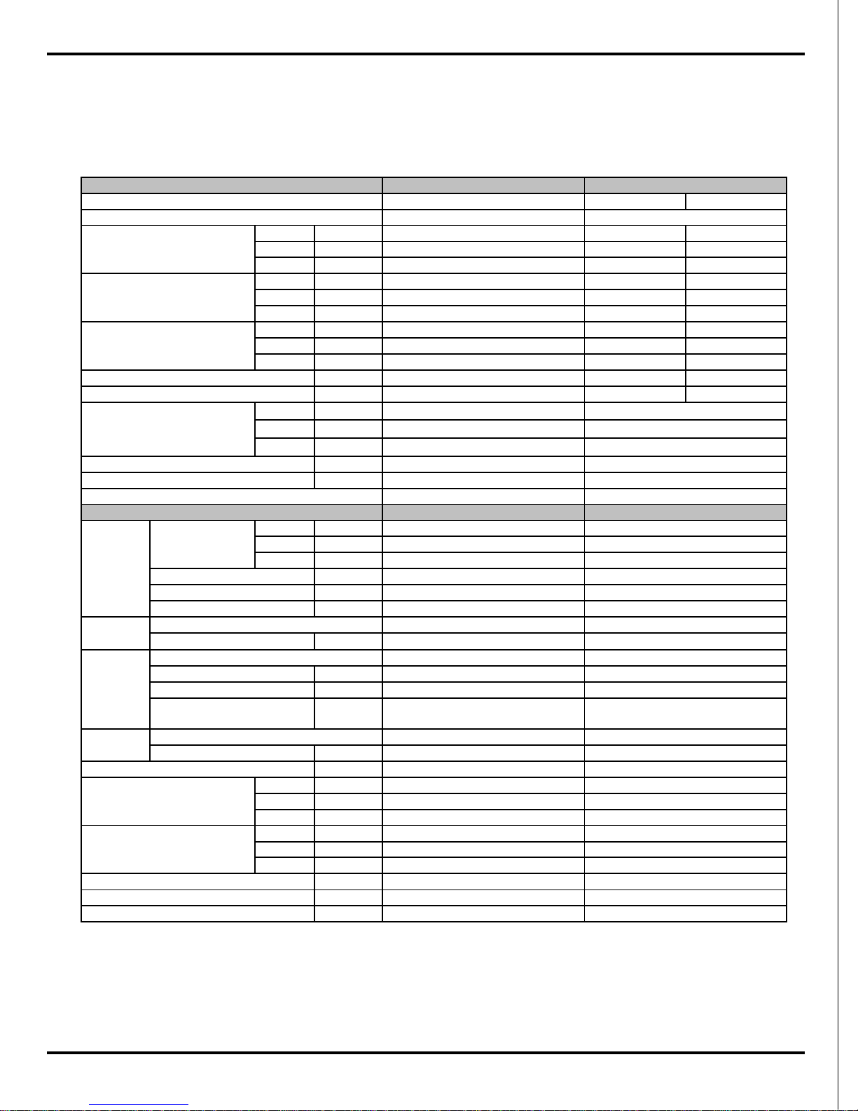
Remarks:
Rating conditions are:
Cooling: Indoor air temperature 27°C D.B. / 19°C W.B.
Outdoor air temperature 35°C D.B. / 24°C W.B.
Heating: Indoor air temperature 20°C D.B.
Outdoor air temperature 7°C D.B. / 6°C W.B.
2.1 Unit Specifications
Models GWC09KF-K3DNA5A, GWH09KF-K3DNA5A
Specifications
4
GWC09KF-K3DNA5A/O GWH09KF-K3DNA5A/O
Manufacturer/trademark DIT/daikin DIT/daikin
1YC23AEXD 1YC23AEXD
L.R.A. ( A) A 4 4
RLA(A) A 4 4
Power Input( W) W 600W 600W
CS-7SA CS-7SA
Capillary Capillary
Tr ansducer st ar ting Tr ansducer starting
℃
5~43 -7~43
Aluminum f in - c opper tube Aluminum fin-copper tube
Pipe Diameter mm 7 7
Rows-Fin Gap mm 1- 1.4 1-1. 4
mm 647X528X19.05 647X528X19.05
Speed rpm 930 930
Output of Fan Mot or W 30 30
RLA A 0.236 0.236
Capacitor μF2 2
m
3
/h
1600 1600
Axial fan -1 Axial fan - 1
Diam e ter mm 37 0 370
A uto defrost Auto defrost
T1 T1
II
IP24 IP24
Mpa 3.8 3.8
Mpa 1.2 1.2
dB (A) 51 5 1
dB (A) 61 6 1
mm 658x550x275 658x550x275
mm 771x348x592 771x348x592
kg 27/31 28/32
R410A R410A
Weight kg 0.74 0.74
Length ( m) m
55
Gas additio nal c har ge g/m
20 20
Liquid Pipe Dia meter mm
Φ
6(1/4”)
Φ
6(1/4”)
Gas Pipe Diameter mm
Φ
9.52(3/8”)
Φ
9.52(3/8”)
m5 5
m15 15
St arting Method
Type
Defrosting Method
Over load Prot ec tor
Air F low Volume of Outdoor Unit
Outdoor Unit
Compress
or
Fan
Fan Motor
Wor k ing Temp Range
Heat
Exchanger
Coil
Coil
Model
Coil lengt h (l) x height (H) x coi l wid th (L)
Thr ottlin g Method
Moisture Protection
Permissible E xc essiv e Operating
Pressure f or the Discharge Side
Permissible E xc essiv e Operating
Pressure for the Suction Side
Type-Piece
Climate T ype
Isolation
Dimension (W×H×D)
Dimension of Pack a ge (L×W× H )
Sound P r essure Level
Sound P ower Level
Net Weight /Gr oss Weight
Connection
Pipe
Max. Interunit Piping Length
Max. Interunit Height Difference
Refrigerant
Name of refriger ant
Specifications
Rotary type
Rotary type
5
COOLING HEA TING
High Hz 92 108
Standard Hz 72 78
Low Hz 15 24
High W / Bt u /h 3960 / 13500 5130 / 1 7500
Standard W / Bt u/h 3530 / 1 2000 4100 / 1 3990
Low W / B tu/h 600 / 2 000 600 / 2 000
High W 1 450 1550
Standard W 1100 1135
Low W 220 220
W 1550 1 650
A6.57.8
H
m
3
/h
M
m
3
/h
L
m
3
/h
l/h
W/W
Hr/min
Mr/min
Lr/min
W
μF
A
mm
mm
mm
mm
W
A
HdB (A)
MdB (A)
LdB (A)
HdB (A)
MdB (A)
LdB (A)
mm
mm
kg
610×294×24
9/12
39
49
770×283×201
844×342×261
25
41
35
31
MP24BA
1.5
PCB 3.15A
1.2
0.16
Cross flow fan – 1
φ92X594
Aluminum fin-copper tube
7
2-1.4
9/12
GWH12KF -K3DNA5A
220-240V
~
560
1.5
3.21/3.61
A/A
GWH12KF -K3DNA5A/I
1150
10
770x283x201
844x342x261
25
41
35
1.5
PCB 3.15A
39
49
31
10
950
1.2
750
3.21
A/A
GWC12KF -K3DNA5A/I
1150
GWC12KF -K3DNA5A
220-240V
~
560
1.5
1550
6.5
1100
3530 / 12000
600 / 2000
COOLING
Energy Class
EER / C.O. P
Speed
Fan Motor
Indoor unit
Model
Function
Rated Voltage
Rated Input
Frequency
(Inv erter differ e nt Compressor
speed)
Total Capacity
(Inv erter differ e nt Compressor
speed)
Power Input
(Inv erter differ e nt Compressor
speed)
92
3960 / 13500
220
1450
72
15
Ai
r F
low Volume
Rated Cur r ent
Fuse (A)
Dimension (W×H×D) ( mm)
Fan
Evaporator
Swing
Motor
Coil length (l)×height (H)×
coil widt h ( L)
Output
Type-Piece
Dimension of P ac kag e (L ×W×H)
Net Weight /Gr oss Weight
Output
Capacitor
RLA
Diameter-Length
Pipe Diameter
Row-F in Gap
Sound P r essure Level
Sound P ower Level
2-1.4
610X294X24
MP24BA
0.16
Cross flow fan - 1
φ92X594
A lu minum fin-cop per t ube
Model
410
300
410
300
950
750
Dehumidifying Volume
7
Remarks:
Rating conditions are:
Cooling: Indoor air temperature 27°C D.B. / 19°C W.B.
Outdoor air temperature 35°C D.B. / 24°C W.B.
Heating: Indoor air temperature 20°C D.B.
Outdoor air temperature 7°C D.B. / 6°C W.B.
Models GWC12KF-K3DNA5A, GWH12KF-K3DNA5A
Specifications
6
GWC12KF-K3DNA5A/O GWH12KF-K3DNA5A/O
Manufacturer/trademark DIT/daikin DIT/daikin
1YC23AEXD 1YC23AEXD
L.R.A. ( A) A 4 4
RLA(A) A 4 4
Power Input( W) W 600W 600W
CS-7SA CS-7SA
Capillary Capillary
Tr ansducer st ar ting Tr ansducer starting
℃
5~43 -7~43
Aluminum f in - c opper tube Aluminum fin-copper tube
Pipe Diameter mm 7 7
Rows-Fin Gap mm 2- 1.4 2-1. 4
mm 647X528X38.1 647X528X38.1
Speed rpm 930 930
Output of Fan Mot or W 30 30
RLA A 0.236 0.236
Capacitor μF2 2
m
3
/h
1600 1600
Axial fan -1 Axial fan - 1
Diam e ter mm 37 0 370
A uto defrost Auto defrost
T1 T1
II
IP24 IP24
Mpa 3.8 3.8
Mpa 1.2 1.2
dB (A) 53 5 3
dB (A) 63 6 3
mm 658x550x275 658x550x275
mm 771x348x592 771x348x592
kg 29/33 30/34
R410A R410A
Weight kg 1.0 1.0
Length ( m) m
55
Gas additio nal c har ge g/m
20 20
Liquid Pipe Dia meter mm
Φ
6(1/4”)
Φ
6(1/4”)
Gas Pipe Diameter mm
Φ
9.52(3/8”)
Φ
9.52(3/8”)
m5 5
m15 15
St arting Method
Type
Defrosting Method
Over load Prot ec tor
Air F low Volume of Outdoo r Unit
Outdoor Unit
Compress
or
Fan
Fan Mot or
Wor k ing Temp Range
Heat
Exchanger
Coil
Coil
Model
Coil length (l) x height (H) x coil width (L)
Thr ottlin g Method
Moisture Protection
Permissible E xc essiv e Operating
Pressure f or the Discharge Side
Permissible E xc essiv e Operating
Pressure for the Suction Side
Type-Piece
Climate T ype
Isolation
Dimension (W×H×D)
Dimension of Pack a ge (L×W× H )
Sound P r essure Level
Sound P ower Level
Net Weight /Gr o ss Weight
Connection
Pipe
Max. Interunit Piping Length
Max. Interunit Height Difference
Refrigerant
Name of refriger ant
Specifications
Rotary type
Rotary type
7
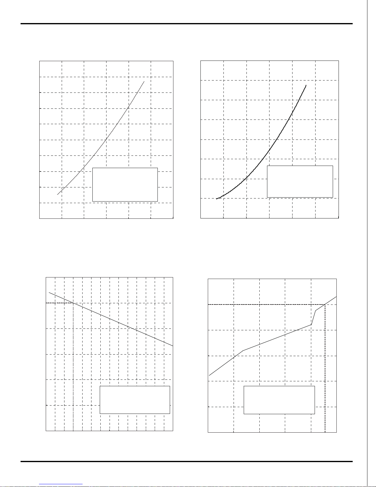
2.2 Operation Characteristic Curve
0
1
2
3
4
5
6
7
8
9
10
0 20 40 60 80 100 120
Condition
Indoor:DB 27ć WB19ć
Indoor air flow: Super High
Pipe length:5m
Voltage:230V
Compressor Speed(rps)
0
1
2
3
4
5
6
7
8
0 20 40 60 80 100 120
Condition
Indoor:DB 20ć
Indoor air flow: Super High
Pipe length:5m
Voltage:230V
Compressor Speed(rps)
Cooling
Heating
Current(A)
Current(A)
2.3 Capacity Variation Ratio According to Temperature
50
60
70
80
90
100
110
32 33 34 35 36 37 38 39 40 41 42 43 44 45 46
Capacity ratio(%)
Condition
Indoor:DB27℃ WB19℃
Indoor air flow: Super High
Pipe length:5m
Outdoor temp. (°C)
0
20
40
60
80
100
120
-15 -10 -5 0 5 10
Capacity ratio(%)
Condition
Indoor:DB20℃
Indoor air flow: Super High
Pipe length:5m
Outdoor temp. (°C)
Cooling Heating
Specifications
8
Cooling
Heating
NOTES :
(1) Measure surface temperature of heat exchanger pipe around center of heat exchanger path U
bent. (Thermistor themometer)
(2) Connecting piping condition : 5 m
2.4 Operation Date
Indoor Outdoor
09K 0.9 to 1.1 53
12K 0.8 to 1.0 72
Outdoor
Fan Mode
Compressor
Revolution(rps)
27/19 35/24 Super High 930rpm
Temp. Cond ition(℃)
Model
Standard
Pressure(Mpa)
Indoo r Fan
Mode
Indoor Outdoor
09K 2.3 to 2.5 72
12K 2.4 to 2.6 78
Outdoor
Fan Mode
Compressor
Revolution(rps)
20/- 7/6 Super High 930rpm
Temp. Cond ition(℃)
Model
Standard
Pressure(Mpa)
Indoor Fan
Mode
Specifications
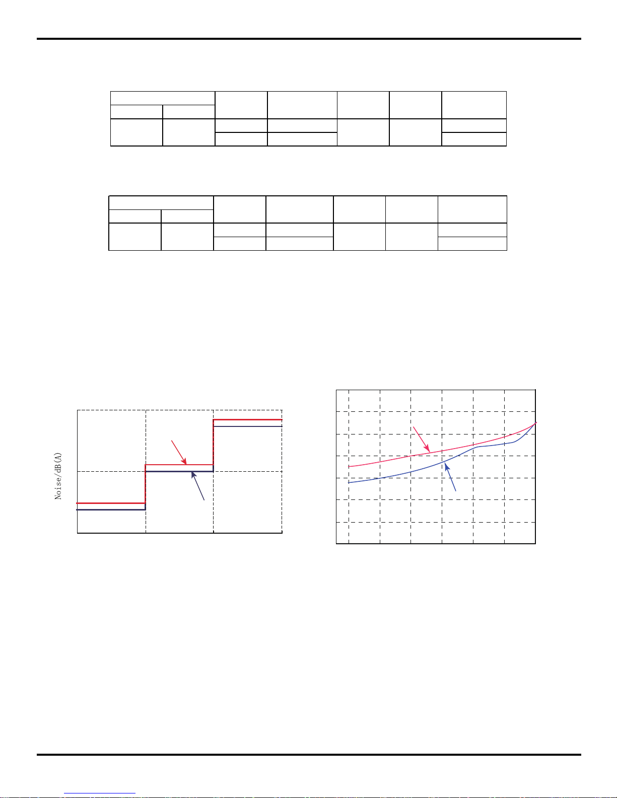
2.5 Noise criteria curve tables for both models
40
42
44
46
48
50
52
54
20 4030 50 60 70 80
Compressor frequency(Hz)
Noise dB(A)
Heating
Cooling
40
30
20
Indoor side noise when blowing
Indoor fan motor rotating speed
Low
Middle
High
12K
09K
9
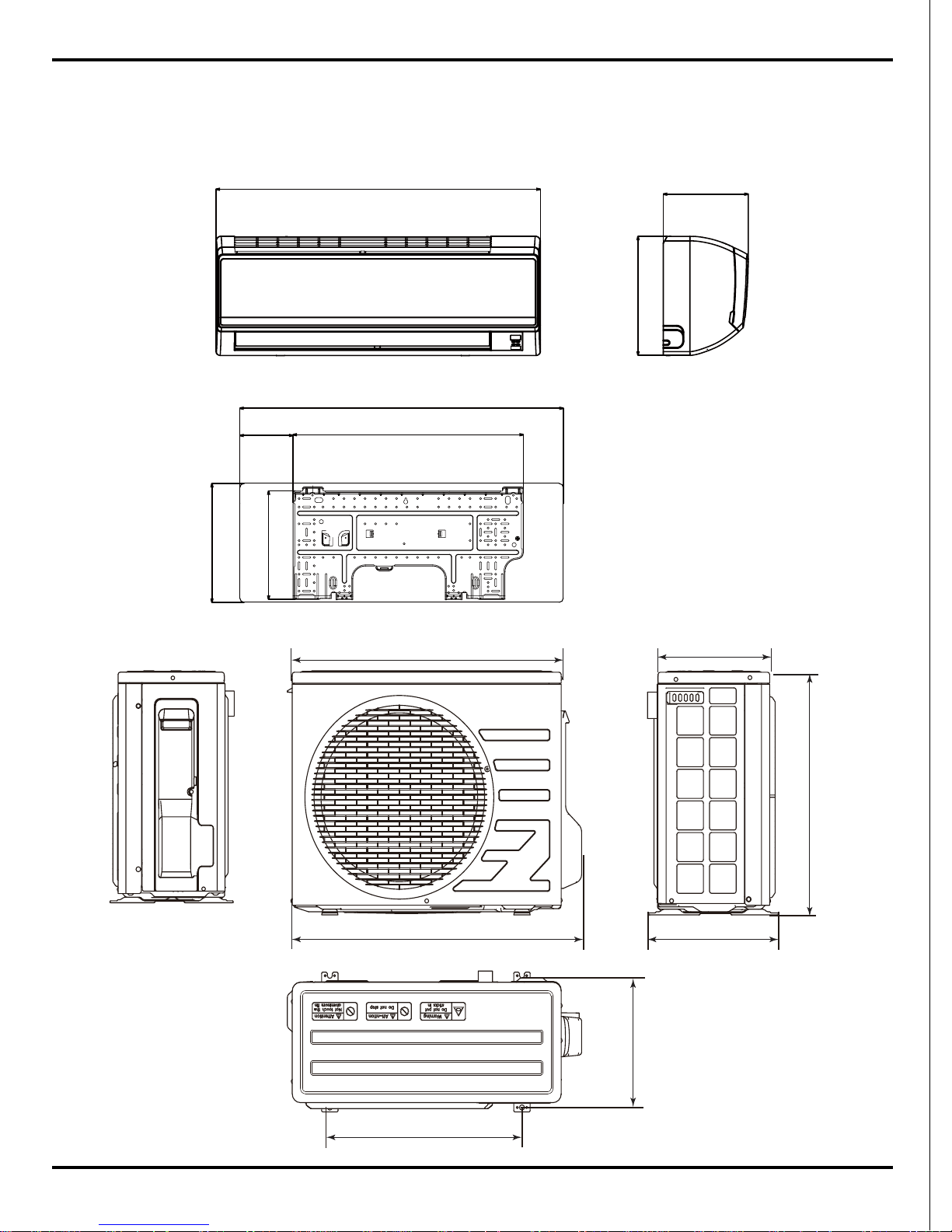
3. Construction Views
3.1 Indoor Unit
3.2 Outdoor Unit
708
658
274
551
317
470
299
Constrction views
770
201
283
548.5
258.5
126.5
770
283
10
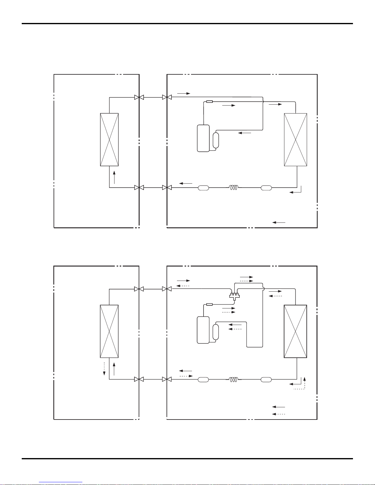
4. Refrigerant System Diagram
INDOOR UNIT OUTDOOR UNIT
HEAT
EXCHANGE
(EVAPORATOR)
HEAT
EXCHANGE
(CONDENSER)
COMPRESSOR
GAS SIDE
3-WAY VALVE
LIQUID SIDE
3-WAY VALVE
COOLING
HEATING
Accumlator
Discharge
Suction
Muffler
4-Way valve
CapillaryStrainer Strainer
Refrigerant pipe diameter
Liquid : 1/4" (6 mm)
Gas : 3/8" (9.52 mm)
INDOOR UNIT OUTDOOR UNIT
HEAT
EXCHANGE
(EVAPORATOR)
HEAT
EXCHANGE
(CONDENSER)
COMPRESSOR
GAS SIDE
3-WAY VALVE
LIQUID SIDE
2-WAY VALVE
COOLING
Accumlator
Discharge
Suction
Muffler
CapillaryStrainer Strainer
(1)Cooling Only Models
(2)Cooling & Heating Models
Refrigerant System Diagram

11
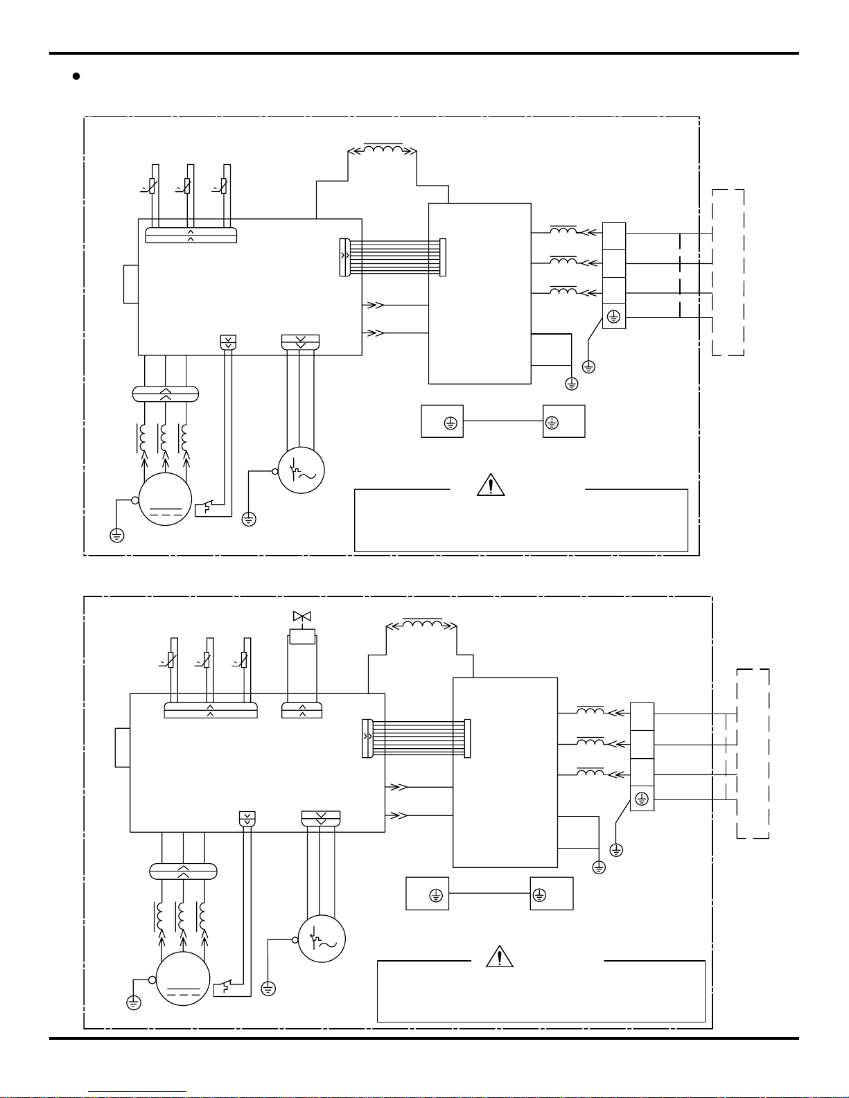
5. Schematic Diagram
5.1 ELECTRICAL DATA
5.2 Electrical wiring
Outdoor Unit
Symbol C ol or symbol Symbol Color symbol
WH
WHITE
BN
BROWN
YE
YELLOW
BL
BLUE
RD
RED
BK
BLACK
YEGN
Y ELLOW G REEN PROTECTIVE EA RT H
Symbol Part s name S ymb ol Color sy mbol
L1
REACROR
WH
WHITE
PCB1~PCB2
PRI NTED CIRCUIT B OA RD
YE
YELLOW
S10/S11S40/S70/S80/S90
CONNECTOR
RD
RED
SAT
OVERLOA D
BN
BROWN
COMP
COMPRESSOR
BL
BLUE
PROTECTIVE EA RTH
BK
BLACK
YEGN
YELLOW GREEN
to the models with cold-plasma function.
NOTE:The parts with broken line is applicable
GENERATOR
COOL PLASMA
HEALTH-L HEALTH-N
AP2
MOTOR
SWING
DISPLAY
OUTDOOR UNIT
TUBE
TEM.SENSOR
ROOM
TEM.SENSOR
FAN
MOTOR
PGM1PGF
SWING-UD
DISP2
L-OUT
AC-L
AP1
BU
BN
BK
COM-OUT
YEGN
PE
BN
BK
RT2
0
DISP1
RT1
2
YEGN
3
YEGN
N
BU
BU
XT
N(1)
L
BN
POWER
M2
N
ROOM
TUBE
0
EVAPORATOR
Indoor Unit
Indoor Unit
Schematic Diagram
12
Outdoor Unit
Models GWC09KF-K3DNA5A ,GWC12KF-K3DNA5A
N(1)
XT
3
2
PE
PCB1
AC2
S
AC1
E1
E2
PCB2
U
V
W
0
RT3
0
RT4
RT5
0
S90
S11S10
HL2
HN2
HN3
HL3
L1
HR2
HR1
FAN
S70
COMP.
HA1
HA2
SAT
PE
S40
PE
PEPE
X1
YEGN
MOTOR
U
V
W
BK
BN
BU
YEGN
YE
OG
CLAPBOARD
BURD
WH
YEGN
BN
BK
BU
BU
BN
BU
YEGN
WH
YERD BU
YEGN
YEGN
OG
EXHAUST
TEM.SENSOR
TEM.SENSOR
OUTROOMOUTTUBE
TEM.SENSOR
ELECTRICAL BOX
SUB-ASSY
YEGN
M
INDOOR UNIT
WARNING
Please don't touch any terminal when the voltage of
prevent the risk of electrical shock!
terminal DC+ and DC- at PCB2 is higher than 30V to
Models GWH09KF-K3DNA5A ,GWH12KF-K3DNA5A
W
V
U
MOTOR
YEGN
X1
4YV
PE PE
PE
S40
PE
SAT
HA2
HA1
COMP.
S70
HR1
HR2
L1
HL3
HN3
HN2
HL2
S10 S11
S80S90
0
RT5
RT4
0
RT3
0
W
V
U
PCB2
E2
E1
AC1
S
AC2
PCB1
PE
2
3
XT
N(1)
WARNING
Please don't touch any terminal when the voltage of
prevent the risk of electrical shock!
terminal DC+ and DC- at PCB2 is higher than 30V to
INDOOR UNIT
M
YEGN
CLAPBOARD
SUB-ASSY
ELECTRICAL BOX
TEM.SENSOR
OUTTUBE OUTROOM
TEM.SENSOR
TEM.SENSOR
EXHAUST
OG
YEGN
YEGN
BURD YE
WH
YEGN
BU
BN
BU
BU
BK
BN
YEGN
WH
RD BU
OG
YE
FAN
YEGN
BU
BN
BK
Schematic Diagram
13
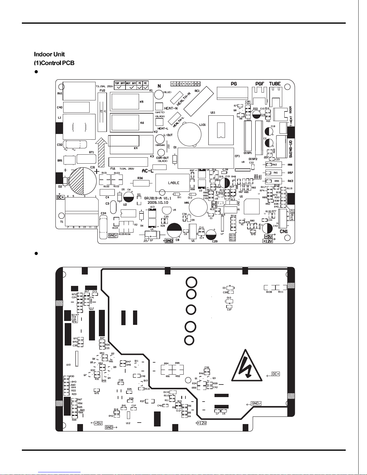
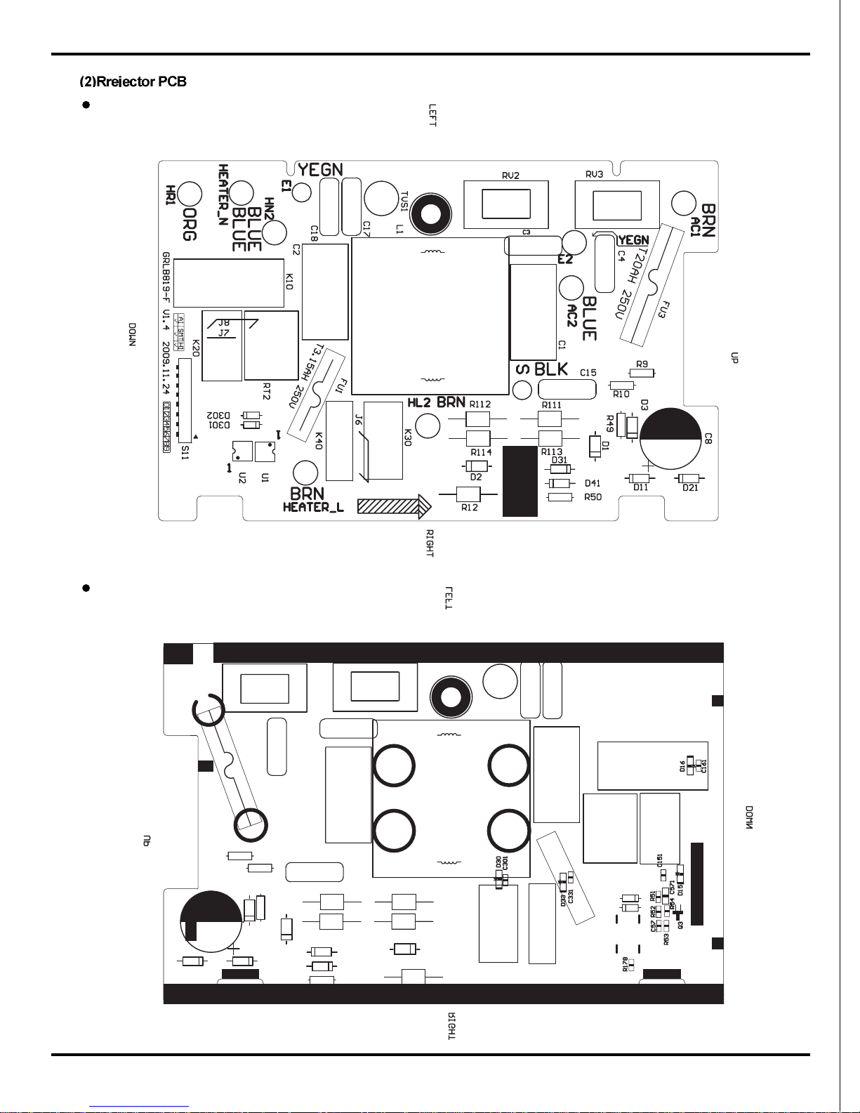
5.3 Printed Circuit Board
TOP VIEW
BOTTOM VIEW
Schematic Diagram
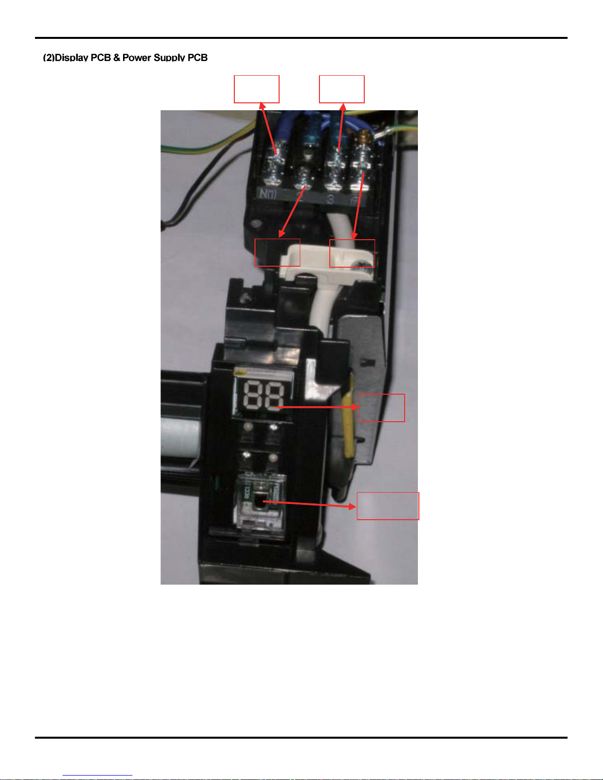
14
zero line
wire under
voltage
communication
wire
dispaly
board
infrared
receiver
Schematic Diagram
ground
wire
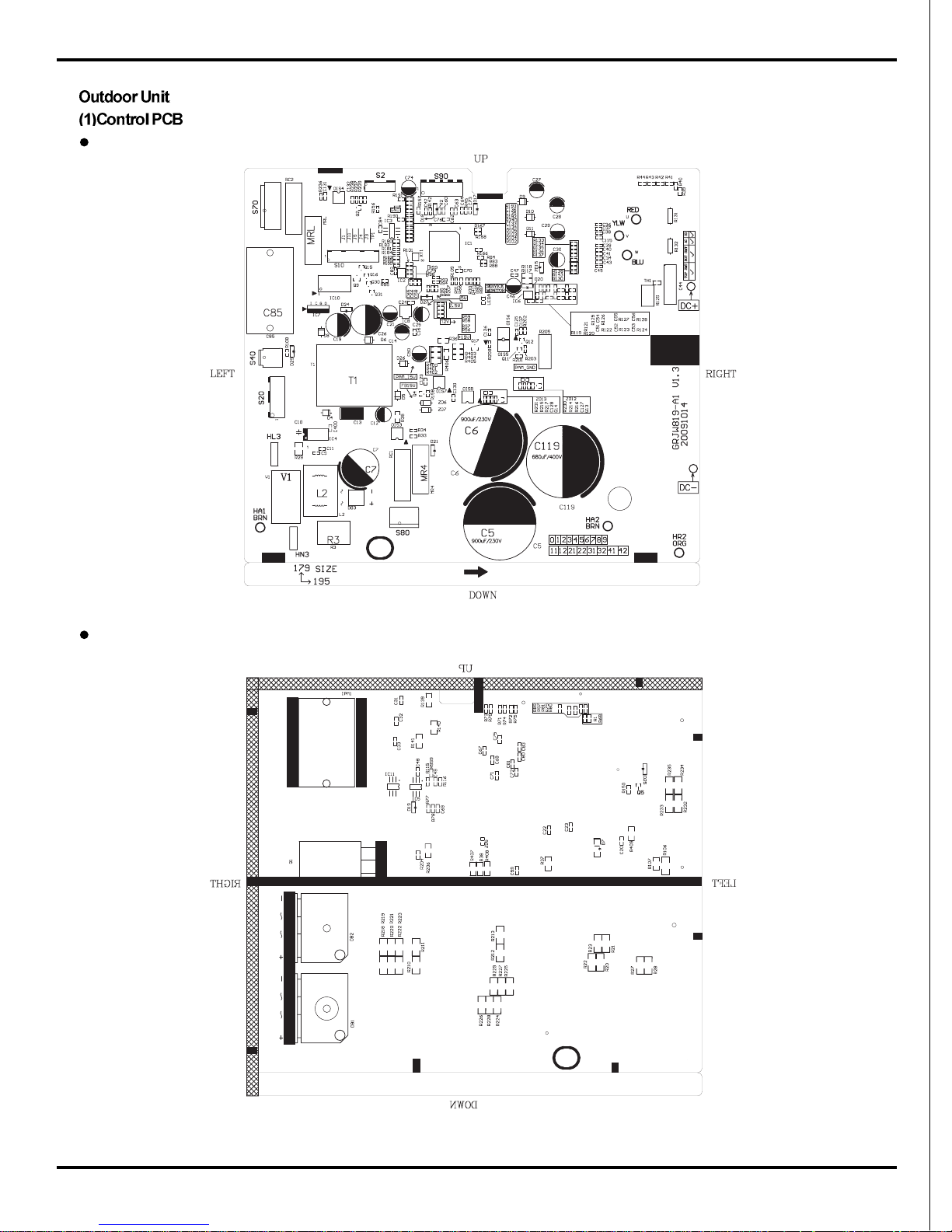
15
TOP VIEW
BOTTOM VIEW
Schematic Diagram
16
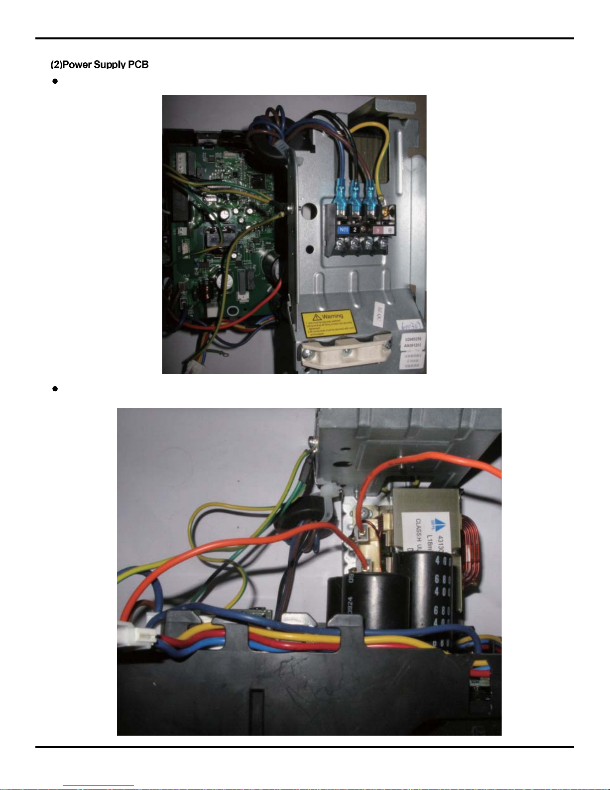
FRONT VIEW
BOTTOM VIEW
Schematic Diagram
17
TOP VIEW
BOTTOM VIEW
Schematic Diagram
18
6. Function and Control
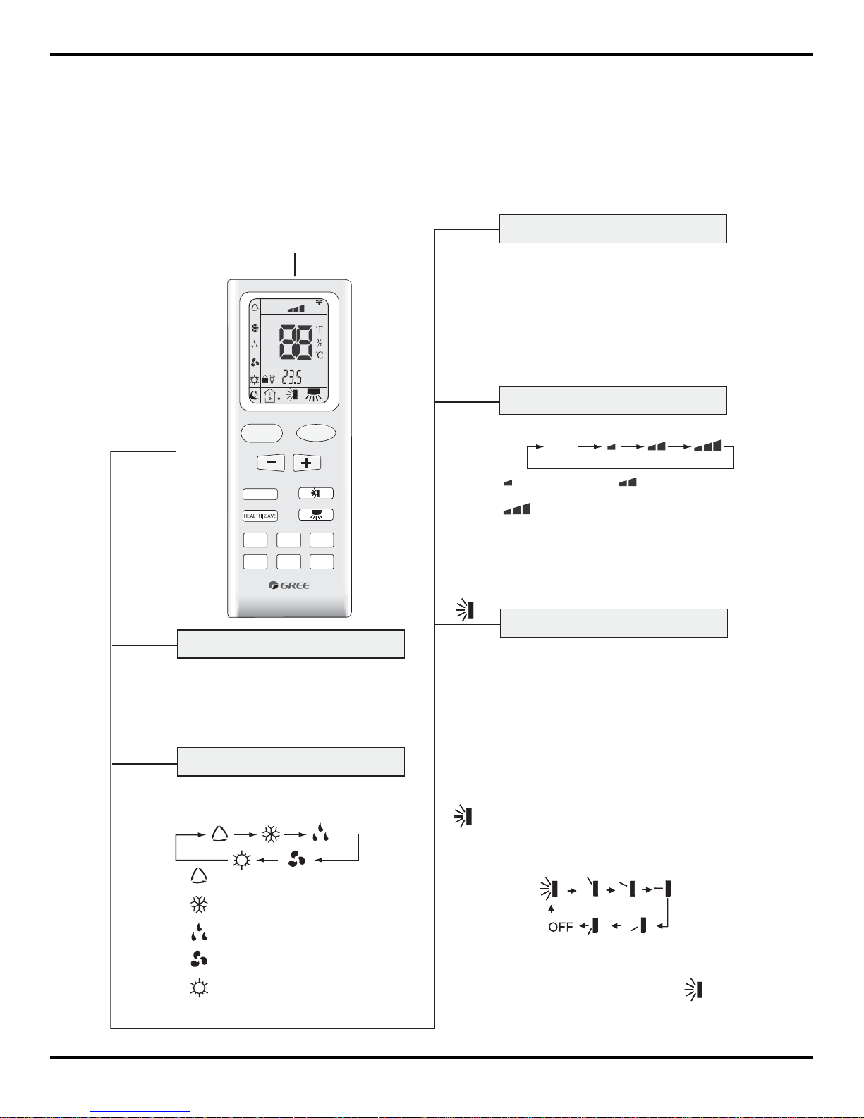
6.1 Remote Control Operations
●
AUTO
COOL
DRY
FAN
HEAT (Note:no for coolling
FAN
FAN speed button
Press this button once, fan speed will change
as below:
Auto
Low speed Middle speed
High speed
Note:Under the Dry mode, the fan speed isn't
●
Simpleness swing mode is defaulted for wireless
remote control, in this mode, press this button,
(ˇ/ˉ)
ćDŽ
●
Note: Be sure that there are no obstructions between receiver and remote control; Don't drop
or throw the remote control; Don't let any liquid in the remote control and put the remote control
directly under the sunlight or any place where is very hot
.
Signal transmitter
Remote control
ON/OFF
ON/OFF button
Press this button, the unit will be started or stopped,
which can clear the timer or sleeping function of
last time.
●
only unit)
TEMP.
button
(ˇ/ˉ)
When press +button , the setting temp. will b
e
increased by 1 ,When press -button,the
setting temp. will be decreased by 1
The temp. will be changed quickly
the button continuously and setting temp. range
ć
is
by pressing
●
●
●
Swing up and down button
ć
below.
Press this button, the running mode
will change as
Mode button
MODE
FAN
AUTO
OPER
HEALTH
AIR
FILTER
TURBO
ON/OFF
BLOW
HOUR
HUMIDITY
ON/OFF
MODE
FAN
BLOW
TURBO
TEMP
TIMER
SLEEP
LIGHT
could turn on or turn off the Up and down
swing function.
When unit is turned off, synchronously press
"+" and Up and down swing buttons, it could
be switched between the simpleness swing
mode and stationary swing mode, at this time,
blinks 2 seconds.
In Stationary swing mode, press this button,the
angle for Up and down swing as show in below:
When up and down swing louver is working,
when turn off the unit, the siwng louver will
●
immediately stop at current position.
shows up and down swing louver swings back
and forth as show in the above figure.
adjustable, low fan speed is imperative,
but when operating this button, the wireless
remote control will send this signal.
Function and Control
19
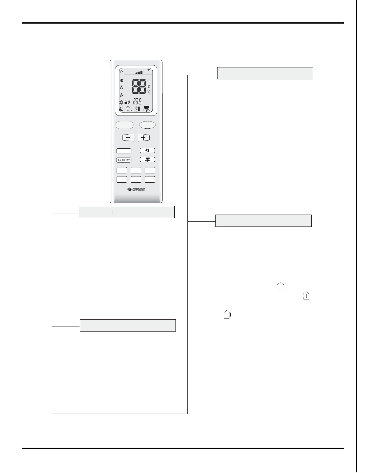
Press this button, (display ), display
the presetting temperature; (display ),
display indoor ambient temperature,
If current display status is indoor ambient temp.
when received other remote control sginal,
then will display presetting temp., 5s later
return to ambient temp. display.
Other models haven't this function. But
pressing this button, the main unit will click
and keep the original status.
no signal display on the remote control).
●
After powered on, displaying presetting
temperature is defaulted,(According to
customer requirements to display,if there
are no requirements,the presetting temperature displaying is defaulted, there is
HEALTH function:there is no this function
for this unit. If press this key, the main unit
will click, but it also runs under original status.
wireless remote control, fan speed automatically
rotates, when repress this button, the fan speed
will run at previous setting fan speed.
FAN
AUTO
OPER
HEALTH
AIR
FILTER
TURBO
ON/OFF
BLOW
HOUR
HUMIDITY
ON/OFF
MODE
FAN
BLOW
TURBO
TEMP
TIMER
SLEEP
LIGHT
TIMER
●
button
Timer button
HEALTH
SAVE
HEALTH SAVE
On the status of the unit on, press this
button to set timer off. On the status of
the unit off, press this button to set timer
off. Press this key once, words Hour on(off)
will appear and flicker. In which case, press
+/- button to adjust time (press+/- button
the setting time range is from 0.5 to 24 hr.
;
continuously to change timing value quickly
then remote controller will send out the signal
immediately and hour on/off will stop flickering.
If the time of that no press timer button
under flickering status is above 5s,the timer
setting will quit. If the timer has been set,
press this button once again to quit it.
press this key once again to fix the time,
●
●
Save energy function: this unit has no this
function, press this button, the mian unit will
click, "SE" will be displayed on the LCD of
Remote control
TURBO
Turbo button
Set turbo on or off(the characters of turbo
will appear or disappear ) by pressing this
●
key unde r cooling or heating mode.Once
energized, the unit will be defaulted to be
turbo off. This function can not be set under
of turbo won't appea r .
auto, dehumidify or fan mode, and characters
TEMP
Temp. display button
(display ), display
ambient temperature,
Function and Control

20
Simpleness swing mode is defaulted for
wireless remote control,in this mode,
press this button, could turn on or turn
off the Left and right swing function
When unit is turned off, synchronously
press "+" and Left and right swing buttons,
it could be switched between the simpleness
swing mode and stationary swing mode,
at this time, blinks 2 seconds.
In Stationary swing mode, press this button,the
angle for Left and right swing as show in below:
When left and right swing louver is working,
when turn off the unit, the siwing louver will
immediately stop at current position.
Left and right swing button
●
●
●
●
shows left and right swing louver swings
back and forth as show in the above figure.
1 , 2 hours later
setting temp.
FAN
AUTO
OPER
HEALTH
AIR
FILTER
TURBO
ON/OFF
BLOW
HOUR
HUMIDITY
ON/OFF
MODE
FAN
BLOW
TURBO
TEMP
TIMER
SLEEP
LIGHT
●
ć
●
●
●
●
Blow button
Set Blow on (the characters of Blow will
appear)or off (the characters of Blow
disappears) by pressing this key under
cool or dehumidify mode. Once energized,
the unit will be defaulted to be Blow off.
This function can not be set under auto,
fan or heat mode, and the characters of
Blow won't appear.
Press this button to select LIGHT on or off
in the displayer. When the LIGHT on is
set,the icon will be displayed and the
indicator light in the displayer will be on.
When the LIGHT off is set, the icon will
be displayed and the indicator light in the
displayer will be off.
Light button
LIGHT
Press this button, enter into SLEEP state,
when repressed, it will quit. The sleep function
and FAN mode.
will be canceled with the stop of the unit.
There is no SLEEP function under AUTO
is the icon for sleep
function.
SLEEP
Sleep button
At COOL mode: the SLEEP mode runs after
1hour, the setting temp. will be increased
by 1 , 2 hour later, setting temp. will be
increased by 2 and then will run at this
setting temperature.
after 1hour, the setting temp
will be
At HEAT mode: the SLEEP mode runs
decreased by
,
then it will run
at setting temperature.
ć
ć
ć
will be decreased by 2
Remote controller
BLOW
Function and Control
 Loading...