

Gree GWC09AA, K5NNA6A Installation And Service Manual
GREE Service Manual GWC09AA / K5NNA6A Page 1
Models: GWC09AA - K5NNA6A
Installation and Service Manual

GREE Service Manual GWC09AA / K5NNA6A Page 2
Imprint
Funds
The publication was funded by the German Federal Ministry
for the Environment, Nature Conservation and Nuclear Safety
within the framework of the International Climate Initiative
based on a decision of the German Federal Parliament.
Federal Ministry for the Environment, Nature Conservation
and Nuclear Safety (BMU)
Programmbüro Internationale Klimaschutzinitiative
Potsdamer Platz 10
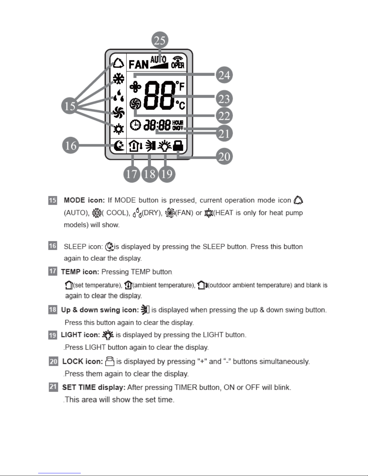
10785 Berlin
E-Mail: programmbuero@programmbuero-klima.de
Phone: +49 (0)30 408 190 - 218
Fax: +49 (0)30 408 190 – 303
Internet: http://www.international-climate-initiative.com
Support
The publication was supported by
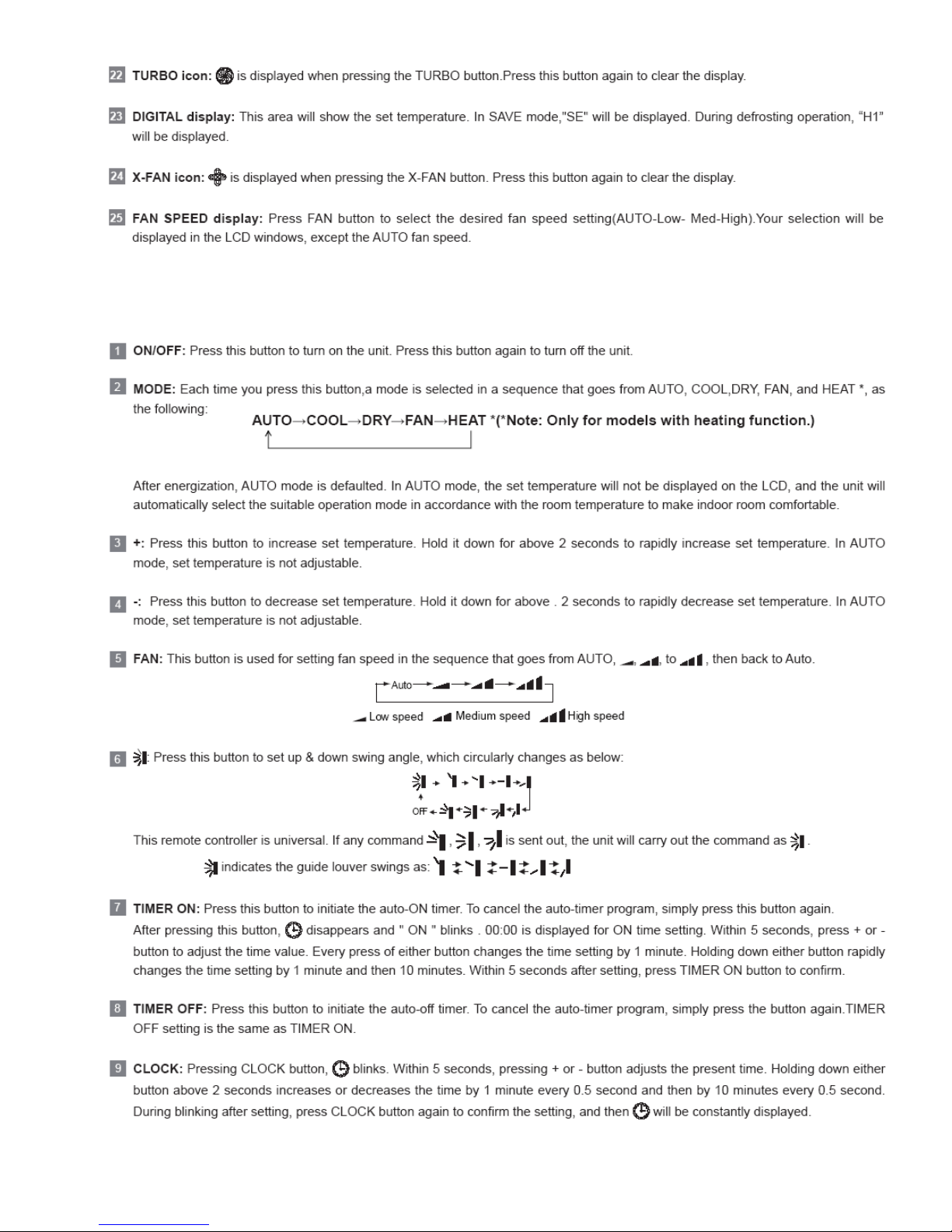
Deutsche Gesellschaft für
Internationale Zusammenarbeit (GIZ) GmbH
– German International Cooperation –
Programme Proklima
Dag-Hammarskjöld-Weg 1-5
65760 Eschborn, Germany
Internet: www.giz.de/proklima
Programme manager: Bernhard Siegele
Contact: bernhard.siegele@giz.de
Authors
GREE Electric Appliances Inc., Rolf Huehren, IKET GmbH
Reviewers
Dr. Daniel Colbourne, Dr. Caroline Narayan
Editors
Rebecca Kirch, Linda Ederberg

GREE Service Manual GWC09AA / K5NNA6A Page 3
Table of Content - 1
Abbreviations used with this manual……………..................... 005 Other adjustments and functions of the remote controller.. 035
Introduction………………………………………….................... 006 Hydrocarbon refrigerant R290 issues………….................. 038
General Safety Instructions………………………..................... 007 Refrigerant properties / parameters………….................. 038
The symbols used in this manual………………................... 007 Flammability…………………………………...................... 039
Electrical operations……………………………..................... 009 Hazard identification………………………….................... 039
Installation site……………………………………................... 009 First aid measures……………………………................... 040
Minimum room size………………………………................... 010 Fire fighting measures……………………….................... 041
Minimum requirements for service personnel qualifica-
tion…………………………………………................................. 011
Accidental release measures…………………................. 041
Basics in RAC…………………………………………............ 011 The handling of HC R290………………………................... 042
Checks for putting in operation…………………………............ 012 Refrigerant recovery………………………….................... 043
Checks for leakage………………………………………............ 012 Repair of leaks………………………………….................. 044
Handling of refrigerant………………………………….............. 012 Refrigerant gas detection…………………….................... 045
Installation, commissioning and maintenance of a compres-
sor………………………………………………........................... 012
Refrigerant cylinder handling………………..................... 046
Installation, commissioning and maintenance of a con-
denser …………………………………………………................ 013
Refrigerant pressure– temperature chart…….................... 048
Installation, commissioning and maintenance of an evapora-
tor…………………………………………………........................ 013
Flow of work for AC system installation, service, repair
and dismantling…………………......................................... 051
Piping………………………………………………………........... 013 AC system Installation………………………….................... 052
Description of the system and its components………….......... 014 Delivery conditions of indoor & outdoor unit.................... 052
General technical specifications………………………........... 014 Principle installation arrangement…………..................... 053
Indoor unit………………………………………………............ 015 Tools, equipment and accessories……………................ 054
Outdoor unit……………………………………………............ 016 Security advise for installation………………................... 055
Refrigerant transfer pipe-set…………………………............. 017 Table of various installation height and resulting room
size…………………………….......................................... 056
Capacity variation ratio according to temperature
(diagram)…………………………………………………............. 018
The installation site > general information…................... 056
Operation data……………………………………………............ 018 Installation site > outdoor unit……………….................... 057
Construction views > indoor unit………………………............. 019 Installation site > indoor unit…………………................... 057
Construction views > outdoor unit………………………........... 020 Installation dimension diagram……………….................. 058
Refrigerant flow diagram……………………………….............. 021 Installation check-list…………………………................... 059
Schematic diagram > Electrical wiring indoor unit……............ 022 Safety measures for electrical equipment……................ 060
Schematic diagram > Electrical wiring outdoor unit…............. 023 Requirements for earthing…………………...................... 060
Printed circuit board (PCB)………………………………........... 024 Miscellaneous…………………………………................... 060
Relay box…………………………………………………............ 026 Installation procedure > indoor unit…………................... 061
Remote controller > functional description……………............ 027 Installation of connection pipes and cables…................. 062
Functional specifications for AC system operation……........... 031 Installation of outdoor unit…………………….................. 065
Cooling mode…………………………………………….......... 031 Interconnection of in– and outdoor unit…….................... 066
Dry mode………………………………………………….......... 032 The quick-coupler valves…………………….................... 067
System protective functions…………………………….......... 033 Commissioning of the AC system………………................. 068
Fan and auto– mode…………………………………….......... 034 Checks before commissioning……………................. 068

GREE Service Manual GWC09AA / K5NNA6A Page 4
Table of Content - 2
Refrigerant circuit commissioning………………................... 068 Service label……………………………………................. 103
First operation of the system……………………................... 068 Dismantling, Recycling and disposal……………................ 104
Indoor unit……..………………………………….................... 068 Error codes, LED flashing and trouble shooting................. 105
Outdoor unit……………………………………….................... 069 Temperature sensor trouble shooting………................... 106
Handing over the system to your client…………..................... 069 PG motor (H6) trouble shooting………………................. 107
Start-up data sheet form…………………………...................... 070 Jumper cap (C5) trouble shooting……………................. 108
Service, repair and maintenance………………….................... 071 Freeze protection (E2) trouble shooting…….................. 109
Directives for service and maintenance…………................. 071 Low pressure (E3) trouble shooting………….................. 110
Regular annual preventive maintenance………………........ 072 PCB board (U8) trouble shooting…………….................. 111
Maintenance of the indoor unit………………………........... 072 Resistance table for temperature sensors……............... 112
Maintenance of the outdoor unit……………………............. 072 Main spare-parts list……………………………................... 115
Refrigerant circuit………………………………………........... 072 Disassembling procedures………………………................. 116
Maintenance check-list………………………………….......... 073 Disassembling the indoor unit……………….................... 116
Safety work area & temporary flammable zones…….......... 074 Disassembling the outdoor unit……………….................. 121
Arrangement of equipment and tools………………….......... 075 Exploded views and part lists………………….................... 126
Refrigerant venting……………………………………............. 076 Exploded view of the indoor unit……………................... 126
Venting > course of activities > part 1…………………......... 077 Part list of the indoor unit…………………...….................. 127
Venting > part 1 > detailed procedure…………………......... 078 Exploded view of the outdoor unit……………................. 128
Venting > course of activities > part 2…………………......... 079 Part list of the outdoor unit…………………….................. 129
Venting > part 2 > detailed procedure…………………......... 080 Recommended equipment and tools for the use with HC
refrigerants…………………………….................................. 130
Equipment for the use of OFDN (N2) in the field……........... 081
Flushing the system with OFDN (N2)………………….......... 083
Flushing the system and provision of “holding charge” with
OFDN > detailed procedure…………….............................. 084
Provision of a hermetically sealed refrigerant circuit............ 085
Leak, strength and tightness testing……………………........ 085
Leak check (bubble test)………………………………........... 087
Electronic gas detectors………………………………............ 088
Leak testing with OFDN & weak soapy water solution......... 089
Leak testing with OFDN and “bubbles” > detailed proce-
dure……………………………………………….................... 090
Trace gas (N2/H2) leak detection method……………........... 091
Trace gas leak detection > detailed procedure………......... 093
Pressure test (strength test) with OFDN………………......... 094
Pressure test (strength test) > detailed procedure……....... 095
Refrigerant circuit > Evacuation and charging……............ 096
Evacuation > detailed procedure………………………......... 099
Charging with refrigerant………………………………........... 100
Charging with refrigerant > detailed description……............ 101
Start-up data sheet form for service and repair………......... 102
GREE Service Manual GWC09AA / K5NNA6A Page 5
Abbreviation Clear Words
AC Air– conditioning
HC Hydrocarbon
LFL Lower flammability level
OFDN Oxygen free and dry nitrogen
PCB Printed Circuit Board
PG motor Indoor unit fan motor
PPE Personnel protective equipment
RAC Refrigeration and air– conditioning
UFL Upper flammability level
Abbreviations used within this manual:

GREE Service Manual GWC09AA / K5NNA6A Page 6
INTRODUCTION
ATTENTION
Please read this manual carefully before installing and operating the GREE Hydrocarbon
Air– Conditioner unit.
Careless installation and operation can cause severe injuries to operators, workers and
damage to the air-conditioner unit itself.
Keep this manual in a location for easy access as it is needed for reference during installation, maintenance, service and operation of the unit.
This manual does not cover all aspects of installation, maintenance and service of the
chiller units; if additional information is needed, contact the GREE Costumer Service or
Sales Office.
General Information
Warning and cautions appear at appropriate locations throughout this manual book.
GREE Service Manual GWC09AA / K5NNA6A Page 7
General Safety Instructions
Please pay careful attention to these safety instructions, to avoid risks to
people and property. Before starting work on maintenance read this manual thoroughly and pay particular attention to the relevant chapters.
Regardless of further requirements of the country in which the equipment
will be installed: assembly, first start up, technical service, maintenance
and repair, as well as dismantling and disposal have to be carried out by
authorised personnel only.
During every operation strictly follow the instructions within this manual.
Pay attention to the specific rules of air conditioning, electrics and refrigerant handling of the country within which the equipment is installed.
Key sections and/or sentences are highlighted with specific icons and
symbols to the right side of the page. Please pay particular attention to
this information.
The symbols used in this manual are as follows:
Information window highlighting important content of the specific section or additional information to consider.
This sign will indicate that you are handling a flammable substance and the surrounding environment can possibly contain it.
This is a general warning sign.
This label is used to indicate that the flammable refrigerant is
present within the application and service equipment
Images that indicate something that you should be strictly
avoided
This is a specific
remark and
points out the
importance of a
specific section
GREE Service Manual GWC09AA / K5NNA6A Page 8
Specific bans!
Specific commandments!
Instructions for first aid!
Fire protection!
Carefully read the instructions
Working on components with safety-relevant functions jeopardises the safe operation of the installation. In case it is necessary to replace components, only
use approved parts from GREE Electric, the Original Equipment Manufacturer
(OEM) or Gree released or authorised components. The system contains the
refrigerant R-290 (propane). This condition requires special safety precautions
to be observed. While working on the system, the presence of any kind of ignition sources (e.g. sparks, open flames, hot surfaces, static electricity) are strictly
prohibited. At the installation site, no matter what kind of activities are executed,
smoking is strictly prohibited!
Likewise, ensure the installation site is well ventilated. For further details on the
handling of the refrigerant R-290 see also pages 11 and 41.
Do not charge the system with any refrigerant which is not R-290! Do not mix
any refrigerants! Before filling the system, ensure that there is no air (or other
non-condensable gases such as nitrogen) left in the system, otherwise there is
severe danger of damage to the system caused by excessive high pressure.
After charging the system with refrigerant, carefully examine and confirm the
tightness by the use of an appropriate electronic leak detector!
ONLY original
GREE (OEM)
spare-parts are
permitted for
Service and Re-
pair!
GREE Service Manual GWC09AA / K5NNA6A Page 9
Electrical operations:
Electric operations (installation, repair, modification, maintenance, adjustment)
have to be fulfilled by trained and authorised personnel only.
When dealing with electrical issues, the specific rules of the country within which
the equipment is installed must be followed, in addition to the instructions within
this manual.
When working on the equipment or parts of it, the system has to be deenergised (by master switch, circuit breaker or separate cut-out) and made safe
against restart of the system. Do not reconnect the system to the electric circuit
until all work is done and all connections are tested.
If handled unsafely or unprofessionally, severe electric shocks can occur. Consider the wiring diagram and follow the instructions of this manual very carefully
whilst working on electrical parts. Wrong connections or incorrect grounding
may lead to severe injuries and mortal danger.
Ground the system according to the particular requirements of the country within
which the equipment is installed.
Connect all the wires properly and durably. Loose cables may lead to overheating or fire.
Installation site:
Ensure that the ceiling or the wall is solid enough to carry the weight of the system which will be mounted on it. Pay attention to the installation of the outdoor
unit: operating noise and air flow should not bother neighbours.
Make sure that appropriate measures are taken against noise emissions, espe-
cially when the system is to be installed close to sensitive facilities (such as hospitals).
Insulate all tube connections professionally to avoid formation of water condensation and water damage to the rooms.
The outdoor unit must be fixed to a flat, stable location. Thereby pay attention
that in that location there is no snow, foliage or dirt accumulating. Take care of
further requirements to prevent the system from damage by earthquakes, hurricanes or high winds.
Do not touch movable parts and keep free from clothing. Do not touch any part
of the system without wearing suitable personnel protective equipment and
clothing in order to avoid injury from: the compressor (hot surface), the refrigerant condenser (hot surface, sharp fins) and the refrigeration tubes (hot and cold
surfaces, sharp spots).
Suitable personnel protective equipment is at a minimum:
1. Goggles
2. Gloves
3. Shoes
4. Overalls
Proceed
according the
manuals
instructions!
Regard
neighbour
protection, avoid
disruptive noise
emissions!
Avoid condensa-
tion of humidity
at tubes and
drains!
Pay attention to
movable parts!
Wear suitable
protective
clothing!

GREE Service Manual GWC09AA / K5NNA6A Page 10
Do not install the system in humid places.
Do not clean the system using water.
Do not energise the system without the suitable air filter assembly to prevent
dust accumulation within itself.
Clean up the installation or service area once work is completed and ensure that
no waste metal parts or wires remain in the equipment housing.
If anything irregular or conspicuous occurs (such as burnt part, smell, loud
noise, etc.) disconnect the system immediately and isolate from the electrical
supply.
Minimum room size
HC R-290 is a flammable refrigerant and can form explosive mixtures in low
concentrations. To minimise the risk of fire or explosion, the system must be installed in a room with a minimum floor area.
Having a
malfunction
while
commissioning,
immediately
disconnect the
system from
mains!
Pay attention to
the room size for
indoor unit
installation!
For specific information refer
page 56 of this
manual.
GREE Service Manual GWC09AA / K5NNA6A Page 11
Minimum requirements for service personal qualification
Unless there are further requirements, standards and legislation of the
country within which the equipment is installed may apply. Any technicians that works on GREE hydrocarbon air–conditioners must be competent in the safe handling of flammable refrigerants, in addition to being in
possession of knowledge and skills to maintain best refrigeration installation and servicing practices!
There are already training activities in place for engineers, technicians and sales
staff to provide professional knowledge and skills for the handling of HC refrigerants and refrigeration systems operating with HCs.
Get trained and have your
“HC Refrigeration Professional” certification!
Basics in RAC
Knowledge of the basic SI standard units for temperature, pressure, mass, density, energy.
Understanding of the basic theory of refrigeration systems including the functions of the main components in the system (compressor, evaporator, condenser, thermostatic expansion valves).
Understanding how to read a refrigerant flow chart and an electrical circuit diagram.
The determination of non-condensable gases in the refrigeration system and
how to eliminate them.
The importance of the use of oxygen free dry nitrogen (OFDN) for system flushing, leak test and strength test.
The elimination of humidity from the refrigeration system and how to recover or
vent HC refrigerant from a system.
Usage of tables and diagrams (log p/h diagram, saturation tables of a refrigerant, diagram of a single compression refrigeration cycle) and interpretation of
these tables and diagrams.
Knowledge of the basic operation of the following components in a refrigeration
system and their role and importance for refrigerant leakage prevention and
identification:
•
Temperature and pressure controls
•
Sight class and moisture indicators
•
Defrost controls, reverse cycle operation
•
System protectors
•
Measuring devices such as the pressure gauge manifold
•
Thermometer
•
Leak detector
•
Refrigerant charging devices
•
Vacuum pump
•
Oxygen free dry nitrogen cylinder and pressure regulator
Fault finding – analysis and repair.
•
Knowledge of flammable refrigerants
•
Risk analysis for the application of flammable refrigerant and properties of
flammable refrigerants
•
Electrical circuit assessment and repair
Get your Best
Practices
knowledge and
skills updated
for HC refriger-
ants and be
certificated for
these jobs!
Read More!
SAFETY CODE
OF PRACTICE
FOR
REFRIGERATING
SYSTEMS
UTILISING A2 &
A3
REFRIGERANTS
ISBN
1 872719 15 5
GREE Service Manual GWC09AA / K5NNA6A Page 12
Checks before putting in operation, after a long period of nonuse, after maintenance or repair intervention or during operation
Carry out a pressure and leak test to check the strength and the tightness of the
system.
Usage of a vacuum pump.
Evacuation of the system to remove air and moisture according to standard
practice.
Checks for leakage
Knowledge of potential leakage points of refrigeration, air-conditioning and heat
pump equipment. Making a visual and manual inspection of the whole system.
Carry out a check for leakage of the system using an indirect method and/or one
of the direct methods.
Direct leak detection methods
1. Fixed leakage detection systems
2. Portable electronic gas detectors
3. Ultraviolet (UV) indication fluids
4. Weak soapy water solution (bubble test) also in combination with OFDN
5. New installation tightness test for leakage detection procedure e.g. H2/N2
6. Operational system tightness test for leakage detection procedure
Indirect refrigerant detection methods:
1. Visual
2. Manual checks
Use of portable measuring devices such as pressure gauges, thermometers and
multi-meters for measuring Volt/Amp/Ohm in the context of indirect methods for
leakage checking and interpretation of the measured parameters.
It is very important to make use of an electronic gas detection device. Take care
that the electronic gas detector is designed and certificated for the use with
flammable refrigerants. Additionally, the electronic HC gas detector must be part
of the Personnel Protective Equipment (PPE) of the technician because if this
device is operational in the work area it will warn by detection and signalling if
HC refrigerant is in the atmosphere.
Handling of the refrigerant during installation, maintenance,
servicing or, recovery or venting
Use scales to weigh refrigerant. Knowledge of the requirements and procedures
for handling, storage and transportation, especially of flammable refrigerants
and especially of contaminated refrigerant and oils. Safe HC refrigerant recovery and venting.
Installation, commissioning and maintenance of a compressor
The basic functioning of a compressor (including capacity control and lubricating
system) and risks of refrigerant leakage to its operation.
Installing a compressor properly, including control and safety equipment.
Adjusting the safety and control switches. Checking the oil return system.
Start up and shut down a compressor and checking the good working conditions
of the compressor, including by making measurements during operation of compressor.
The use of OFDN
is important and
the HC gas de-
tector is indeed a
personnel pro-
tection device
(PPE)!
GREE Service Manual GWC09AA / K5NNA6A Page 13
Installation, commissioning and maintenance of condensers
The basic functioning of a condenser.
Installing a condenser properly, including control and safety equipment.
Adjusting the safety and control switches. Checking the hot-gas and liquid lines
in correct positions. Start up and shut down a condenser and check the good
working conditions, including by making measurements during operation.
Checking the surface of the condenser. Methods for condenser surface cleaning
and fins adjustments.
Installation, commissioning and maintenance of evaporators
The basic functioning of an evaporator (including defrosting system).
Installation of an evaporator including control and safety equipment.
Adjusting the safety and control switches.
Checking the liquid and suction pipelines in the correct position and checking
the hot gas defrost pipeline. Start up and shut down an evaporator and check
the good working of the evaporator, including by making measurements during
operation. Functional checking of the reverse cycling control device.
Checking the surface of the evaporator. Methods for evaporator surface cleaning and fins adjustments.
Piping
Professional brazing is another key component for safe and state-of-the-art HC
system installation and servicing. Brazing leak-free joints on metallic tubes and
pipes that can be used in refrigeration, air-conditioning or heat pump systems.
Make/check pipe and component supports and vibration elimination. Knowledge
about the designing and dimensioning of the different refrigeration system section pipes including risers. The behaviour of lubricants within the refrigeration
system and the influences of the dimensioning of pipe work in relation to lubricants. Develop strategies to minimise mechanical connections like flaring or
flanges and to provide a sealed (hermetic) system.
Regular
professional
brazing
experience is an
important pre-
condition for the
work with
hydrocarbon
refrigerants!
Preventive
maintenance will
improve the sys-
tem efficiency
GREE Service Manual GWC09AA / K5NNA6A Page 14
Description of the system and its components
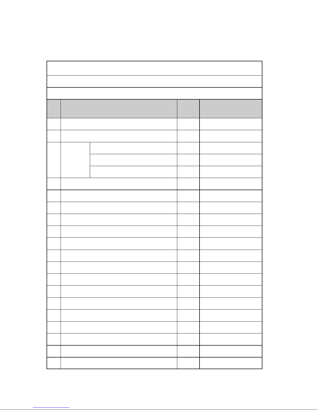
Unit Specifications GWC09AA—K5NNA4A
General Technical Specifications
Split-type On/Off
Item
No
Parameter Unit Value
1 Model
GWC09AA-K5NNA4A
2 Product Code CA115012800
3
Power Supply
Rated Voltage
V~
220-240
Rated Frequency Hz 50
Phases 1
4 Power Supply Mode Indoor
5 Cooling Capacity W 2650
6 Heating Capacity W NA
7 Cooling Power Input W 883
8 Heating Power Input W NA
9 Cooling Power Current A 3.92
10 Heating Power Current A NA
11 Rated Input W 995
12 Rated Current A 4.41
13 Air Flow Volume( SH/H/M/L/SL) m3/h 480/460/420/380/14 Dehumidifying Volume L/h 0,8
15 EER W/W 3,0
16 COP W/W NA
17 SEER W/W NA
18 HSPF W/W NA
19 Application Area m
2
12-18
GREE Service Manual GWC09AA / K5NNA6A Page 15
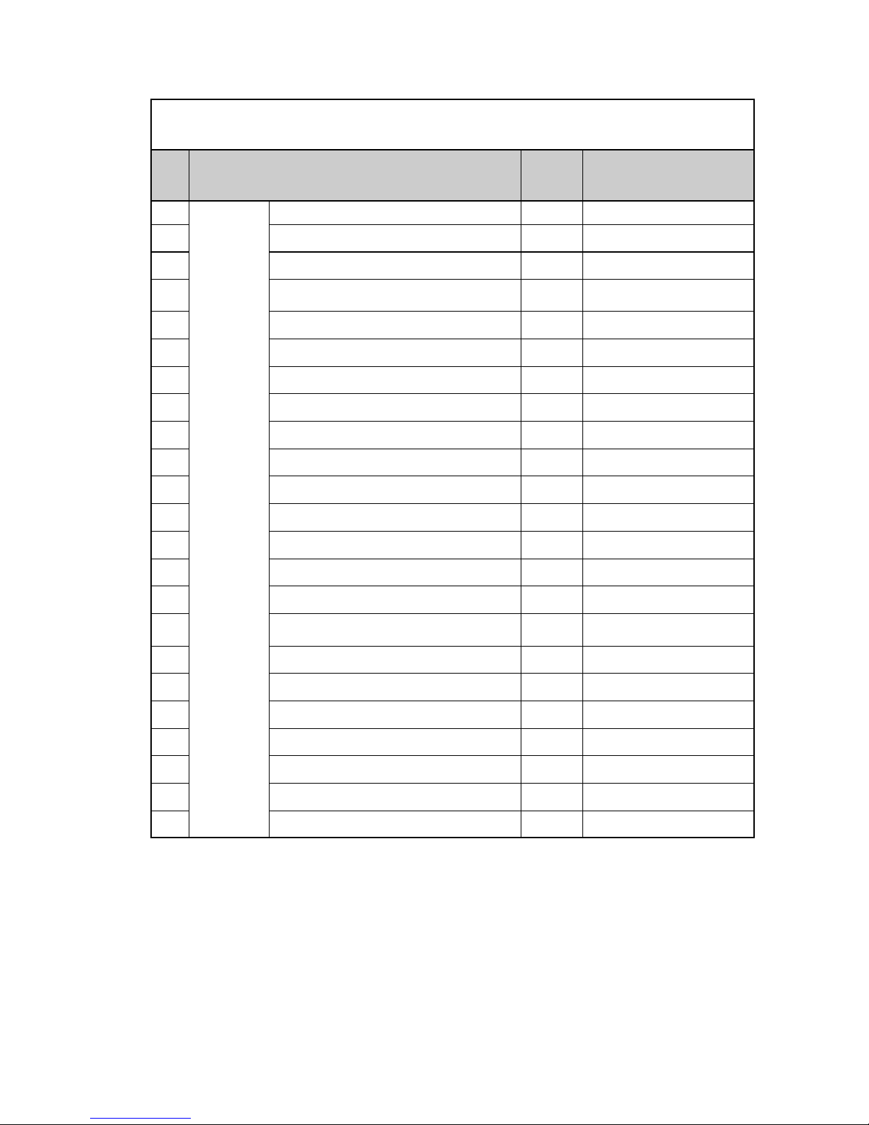
Indoor
Unit
20 Model of indoor unit
GWC09AA-K5NNA4A/I
21 Fan Type Cross-flow
22 Diameter Length( D x L) mm Ø 85x615
23 Fan Motor Cooling Speed (SH/H/M/L/SL) r/min 1350/1150/1050/950/24 Fan Motor Heating Speed (SH/H/ML/SL) r/min NA
25 Output of Fan Motor W 10
26 Fan Motor RLA A 0.10
27 Fan Motor Capacitor µF 1
28 Input of Heater W NA
29 Evaporator Form Aluminium Fin-copper Tube
30 Pipe Diameter mm Ø 7
31 Row-fin Gap mm 2-1.6
32 Coil Length (LXDXW) mm 603X264X25.4
33 Swing Motor Model MP28VB
34 Output of Swing Motor W 2
35 Fuse A
PCB 3.15A Transformer
0.2A
36 Sound Pressure Level (SH/H/M/L) dB (A) 38/36/33/30
37 Sound Power Level (SH/H/M/L) dB (A) 48/46/43/40
38 Dimension (WXHXD) mm 815×165×267
39 Dimension of Carton Box (L/W/H) mm 975×320×385
40 Dimension of Package(L/W/H) mm 978X323X400
41 Net Weight kg 14
42 Gross Weight kg 18
Item
No
Parameter Unit Value
Indoor Unit
GREE Service Manual GWC09AA / K5NNA6A Page 16
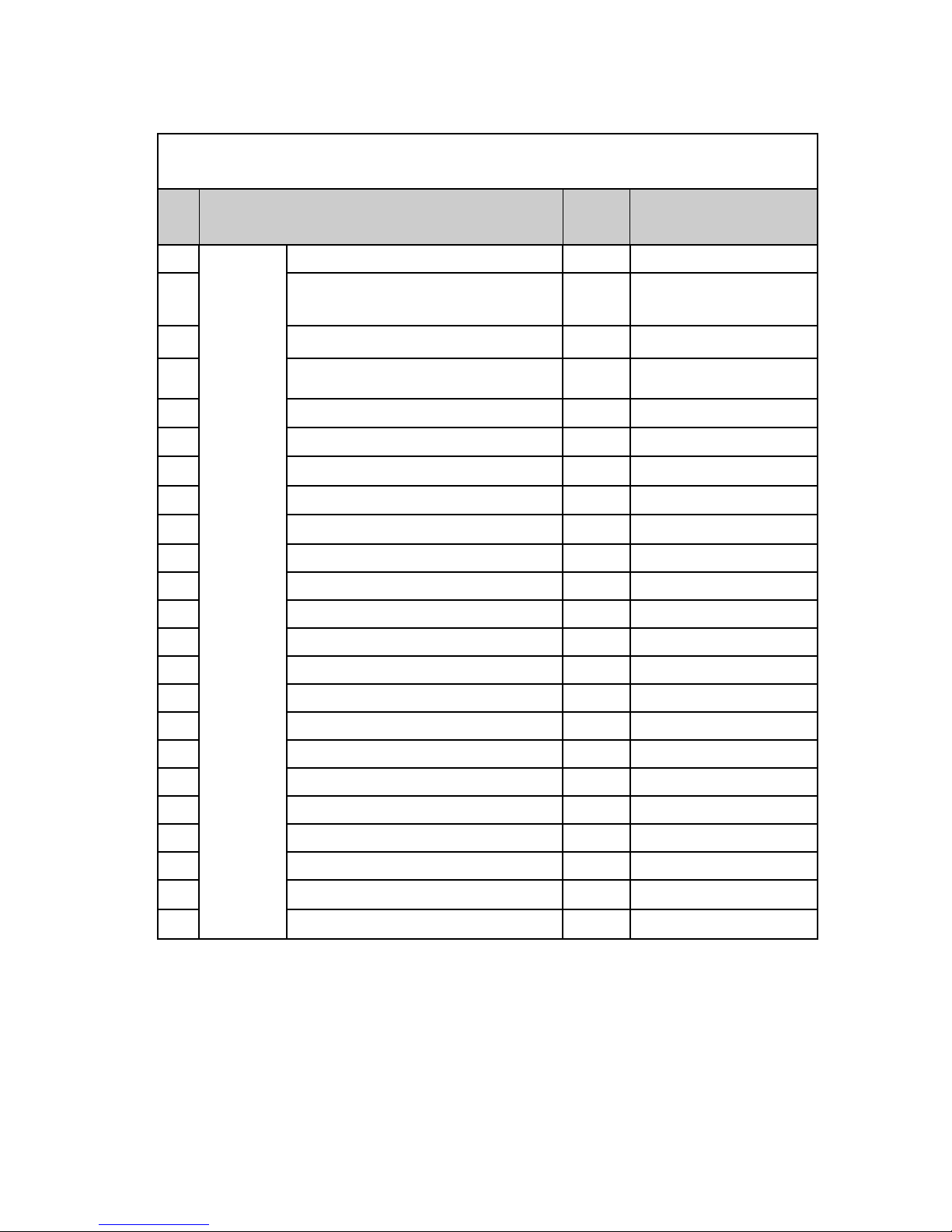
43
Outdoor
Unit
Model of Outdoor Unit GWC09AA-K5NNA4A/O
44 Compressor Manufacturer/Trademark
ZHUHAI LANDA COMPRES-
SOR CO,LTD/GREE
45 Compressor Model QXD-C184A030A
46 Compressor Oil CP2922HT(EXP3535)
47 Compressor Type Rotary
48 L.R.A. A 21.00
49 Compressor RLA A 3.90
50 Compressor Power Input W 820
51 Overload Protector Internal
52 Throttling Method Capillary
53 Operation Temp ℃
16ºC~30ºC
54 Ambient Temp (Cooling) ℃
18ºC~43ºC
56 Condenser Form Aluminium Fin-copper Tube
57 Pipe Diameter mm Ø5
58 Rows-fin Gap mm 1-1.3
59 Coil Length (LXDXW) mm 741×495.3×12.7
60 Fan Motor Speed rpm
860±20
61 Output of Fan Motor W 25
62 Fan Motor RLA A 0,45
63 Fan Motor Capacitor µF 2.5
64 Air Flow Volume of Outdoor Unit m3/h 1800
65 Fan Type Axial-flow
66 Fan Diameter mm Ø400
Item
No
Parameter Unit Value
Outdoor Unit
GREE Service Manual GWC09AA / K5NNA6A Page 17
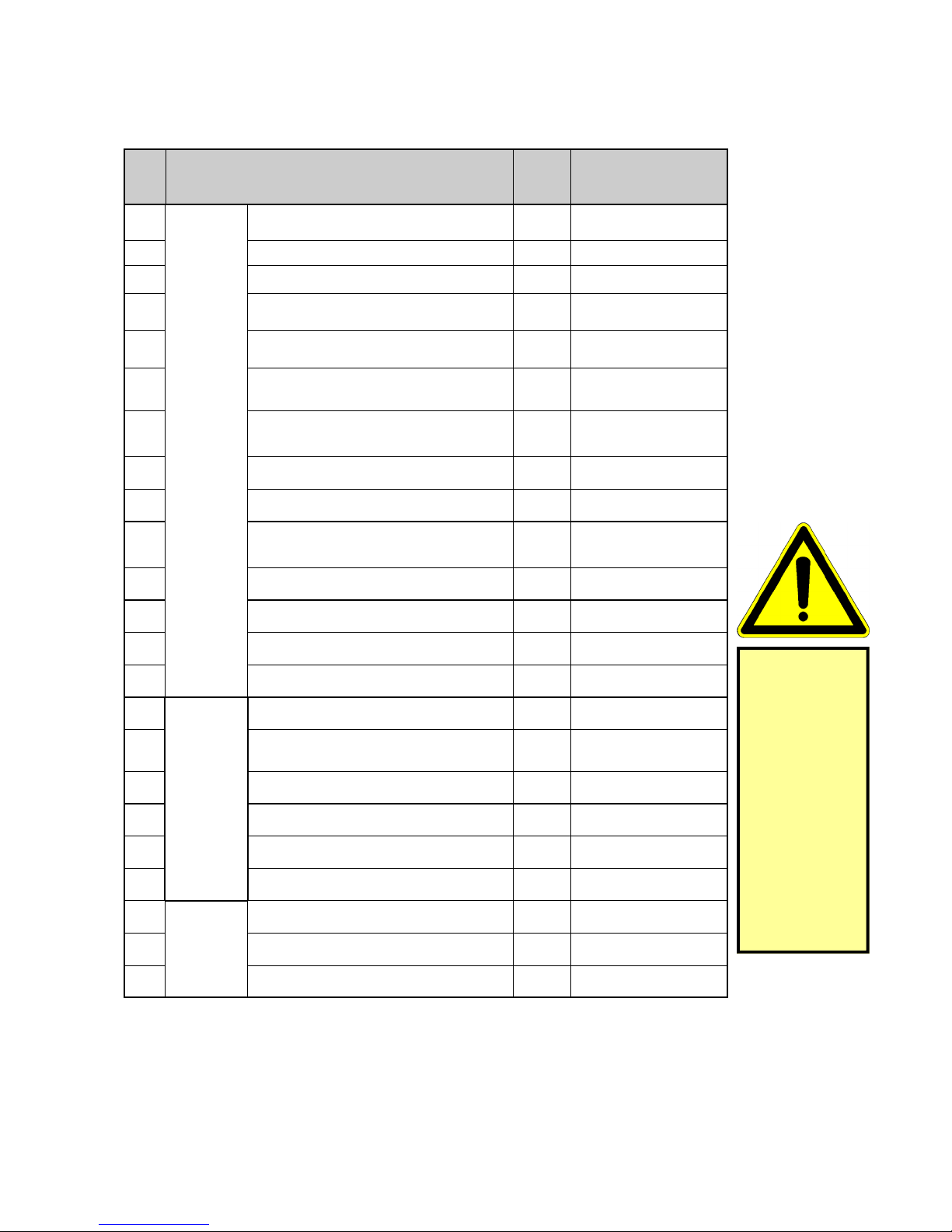
68
Outdoor
Unit
Climate Type T1
69 Isolation
I
70 Moisture Protection
IP24
71
Permissible Excessive Operating Pressure for the Discharge Side
MPa 2.5
72
Permissible Excessive Operating Pressure for the Suction Side
MPa 0.5
73 Sound Pressure Level (H/M/L) dB (A)
50
74 Sound Power Level (H/M/L) dB (A)
60
75 Dimension (WXHXD) mm 848X540X320
76 Dimension of Carton Box (L/W/H) mm 878X360X580
77 Dimension of Package (L/W/H) mm
881X363X595
78 Net Weight kg 35
79 Gross Weight kg 39
80 Refrigerant R-290
81 Refrigerant Charge kg 0.20
Connection Pipe
82 Length m 5
83 Gas Additional Charge g/m
Not Permitted
84 Outer Diameter Liquid Pipe mm Ø 6
85 Outer Diameter Gas Pipe mm Ø12
86 Max Distance Height m 4
87 Max Distance Length m 5
88
Container
Loading
Quantity
20'GP set 95
89 40' GP set 198
90 40' HQ set 225
Item
No
Parameter Unit Value
The unit is an
INTRINSIC SAFE
System!
Refrigerant
charge is limited
to 200 gram
Top-up of
charge is not
permitted
Modification of
system and in
specific the pre-
assembled
pipe-length is
not permitted!
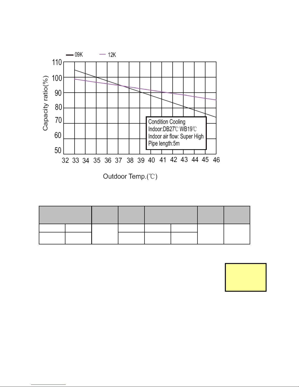
GREE Service Manual GWC09AA / K5NNA6A Page 18
Capacity Variation Ratio According to Temperature
Cooling Mode Only
Operation Data
Notes:
1. Measure surface temperature of heat exchanger pipe around centre of
heat exchanger path (U-Bend) (Thermistor Thermometer)
2. Connection piping conditions (Liquid / Suction) fixed at 5 m
3. P = Suction - Pressure of refrigerant measured at service port connection
4. T1 = Inlet and Outlet Temperature of evaporator (pipe surface Temperature)
5. T2 = Inlet and Outlet Temperature of condenser (pipe surface Temperature)
Temperature Condi-
tions in °C
Model
Name
Standard
Pressure
Heat Exchanger
Pipe Temperature
Indoor
Fan
Mode
Outdoor
Fan
Mode
Indoor Outdoor
9K
P (MPa) T1 (°C) T2 (°C)
Super
High
860
27/19 35/24 0.5 to
0.6
8 to 11 83 to 38
Modification of
pipe-length is
not permitted!
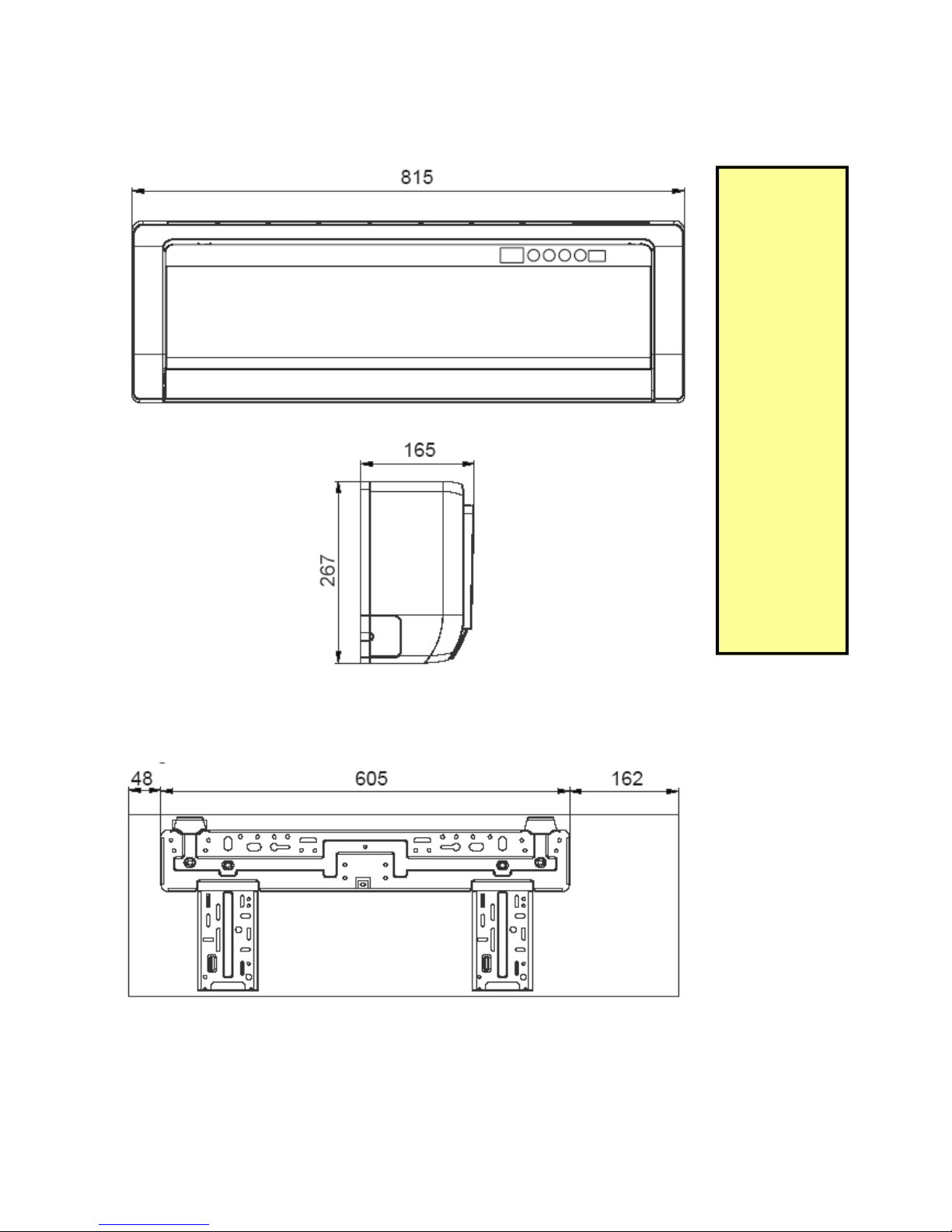
GREE Service Manual GWC09AA / K5NNA6A Page 19
Construction Views
(All Dimensions in mm)
Indoor Unit
Wall Mounted Plate
The indoor unit
is equipped with
pre-fixed and
isolated refrigerant transfer
pipes!
The length of the
pipes is 5 m.
The indoor-unit
is pre-charged
with HC R-290
refrigerant
In addition prefixed is:
1. Electrical connections between indoor
and outdoor
unit
2. Mains-supply
cable with
plug
3. Condensate
drain pipe
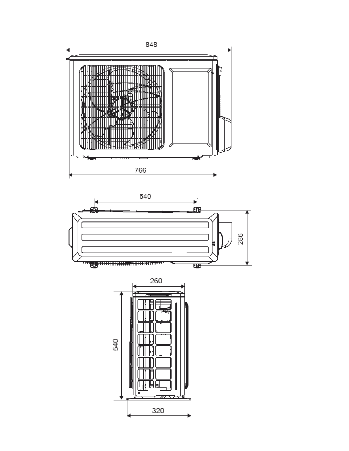
GREE Service Manual GWC09AA / K5NNA6A Page 20
Outdoor Unit
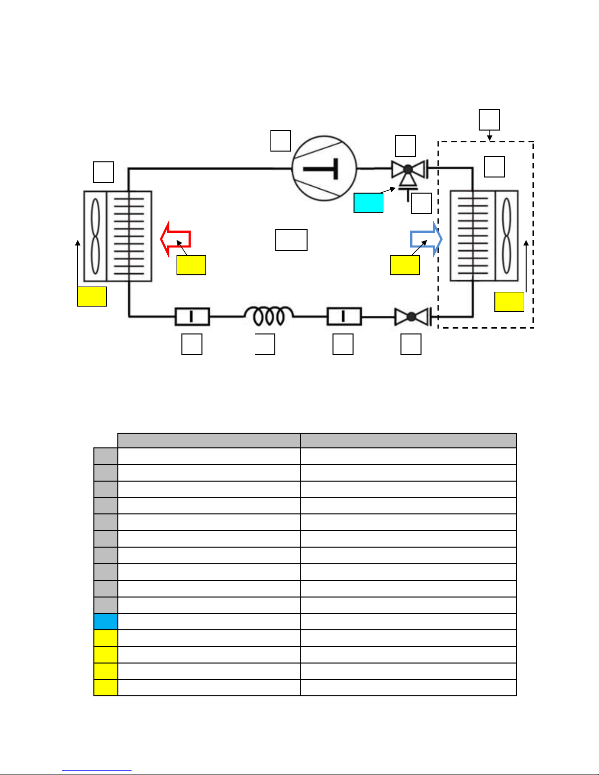
GREE Service Manual GWC09AA / K5NNA6A Page 21
Refrigerant Flow Diagram
Designation Remark
1 Compressor Rotary scroll
2 Condenser Finned Heat Exchanger
3 Evaporator Finned Heat Exchanger
4 Capillary tube Refrigerant expansion device
5 Strainer Refrigerant filtering device
6 2 - way valve Stop valve
7 3 – way valve Stop valve and ¼” SAE service port
9 Indoor unit Pre-assembled with 5 m refrigerant transfer pipes
10 Outdoor unit
P1 Suction pressure R-290 low pressure gauge measuring
T1 Temperature Air- inlet Room air entering evaporator
T2 Temperature Air- outlet Room air leaving evaporator
T3 Temperature Air- inlet Outside air entering the condenser
T4 Temperature Air- outlet Outside air leaving the condenser
8 Service Port 1/4” NPT
P1
T1 T3
T4
T2
5 4 5
2
1
7
9
3
6
10
8
GREE Service Manual GWC09AA / K5NNA6A Page 22
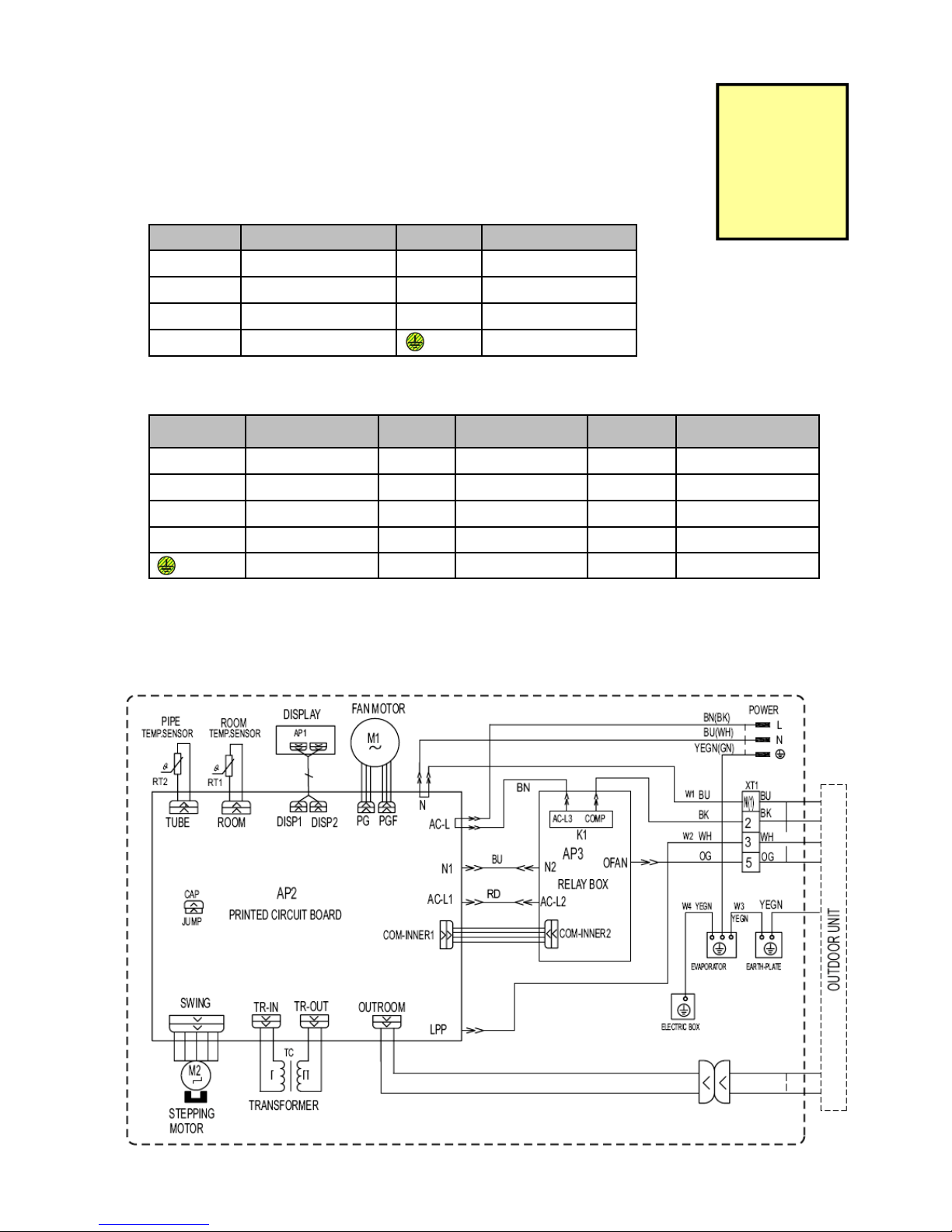
Schematic diagram
Electrical Data
Meaning of Marking
•
Indoor Unit
•
Outdoor Unit
Electrical Wiring - Indoor Unit
These circuit diagrams are subject to change without notice, please refer to the one supplied with the unit.
Symbol Colour Symbol Symbol Colour of Symbol
BU Blue BN Brown
YE Yellow WH White
RD Red BK Black
YEGN Yellow / Green Protective Earth
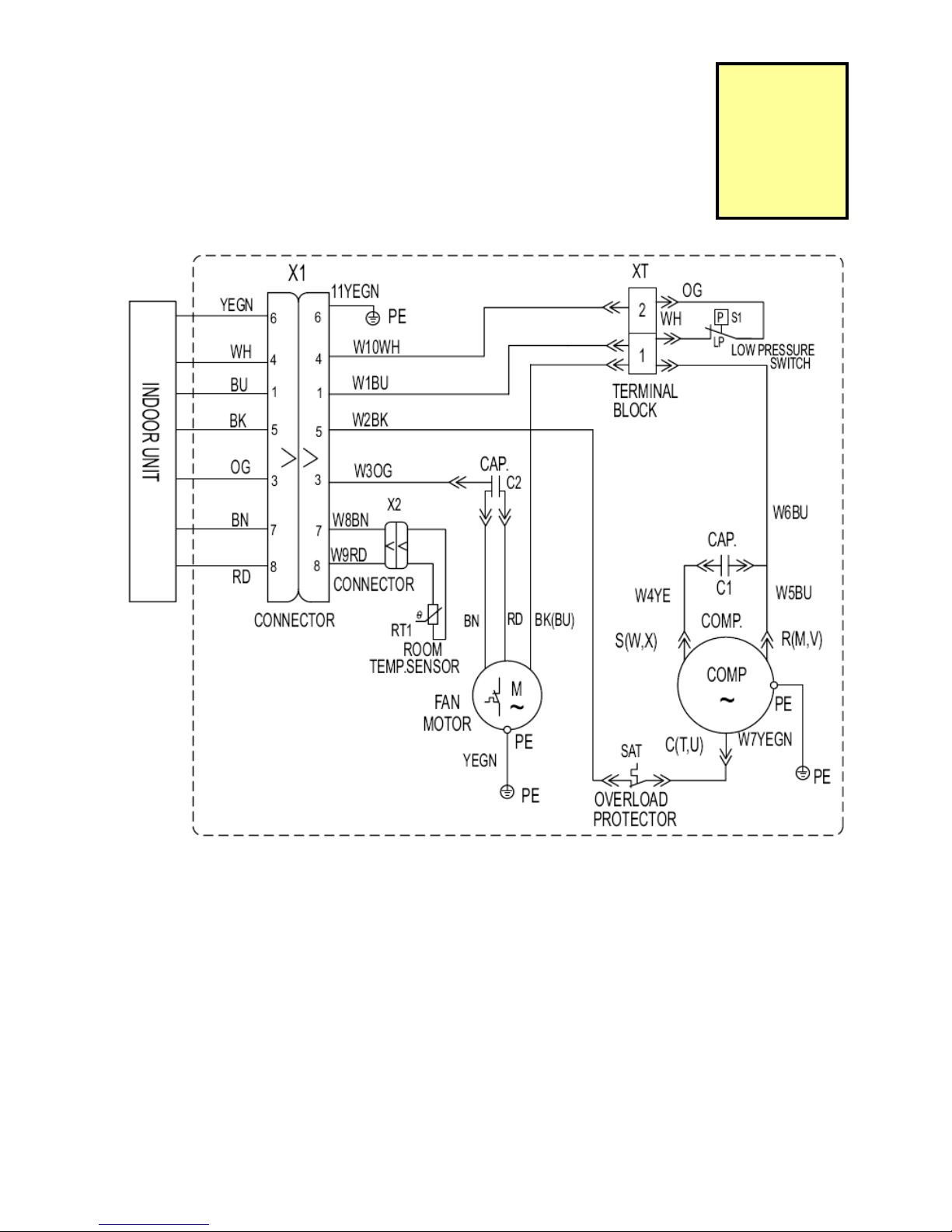
Symbol Parts Name Symbol Colour Symbol Symbol Colour of Symbol
C1 CBB61 BN Brown WH White
C2 CBB65 BU Blue YE Yellow
SAT Overload BK Black RD Red
COMP Compressor OG Orange YEGN Yellow / Green
Protective Earth GN Green
Do not modify
electrical com-
ponents or
wiring, for
replacements.
Only use OEM
spare-parts!
GREE Service Manual GWC09AA / K5NNA6A Page 23
Electrical Wiring - Outdoor Unit
These circuit diagrams are subject to change without notice, please refer to the one supplied with the unit.
Do not modify
electrical com-
ponents or
wiring, for
replacements
only use OEM
spare-parts!
GREE Service Manual GWC09AA / K5NNA6A Page 24
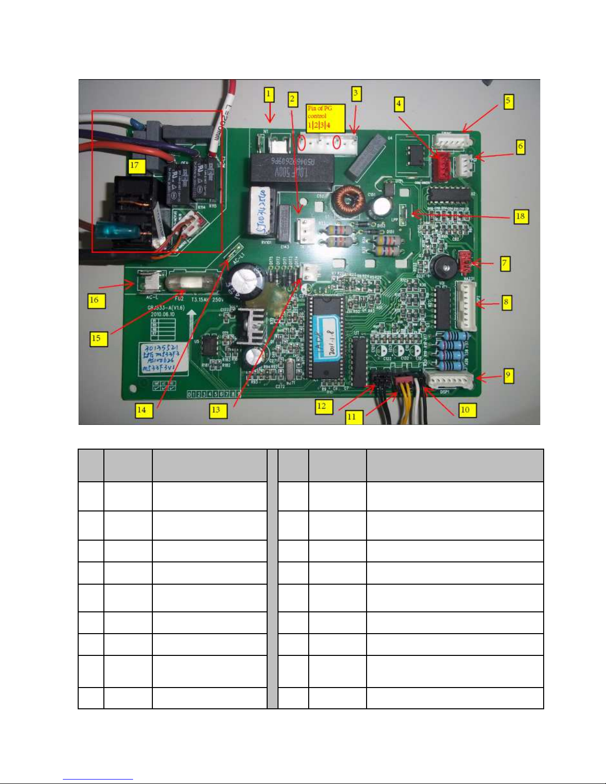
Printed Circuit Board (top-view)
No. Interface Name
No. Interface Name
1 Neutral wire of PCB 10 Outdoor ambient temperature sensor
2
Transformer input
terminal
11 Indoor ambient temperature sensor
3 PG motor control 12 Indoor tube temperature sensor
4
Relay box control
13 Transformer output terminal
5 Swing motor control 14 Live wire input terminal of relay box
6 PG motor feedback 15 Fuse
7 Jumper cap 16 Live wire input
8 Display connector 2 17
PCB indoor unit relay box
9 Display connector 1 18 Low pressure switch
Name
on PCB
board
N, N1
TR-IN
PG
COM—
INNER1
SWING
PGF
JUMP
DISP2
DISP1
Name
on PCB
board
OUTROOM
ROOM
TUBE
TR-OUT
AC-L1
FU2
AC_L
/
LPP
GREE Service Manual GWC09AA / K5NNA6A Page 25
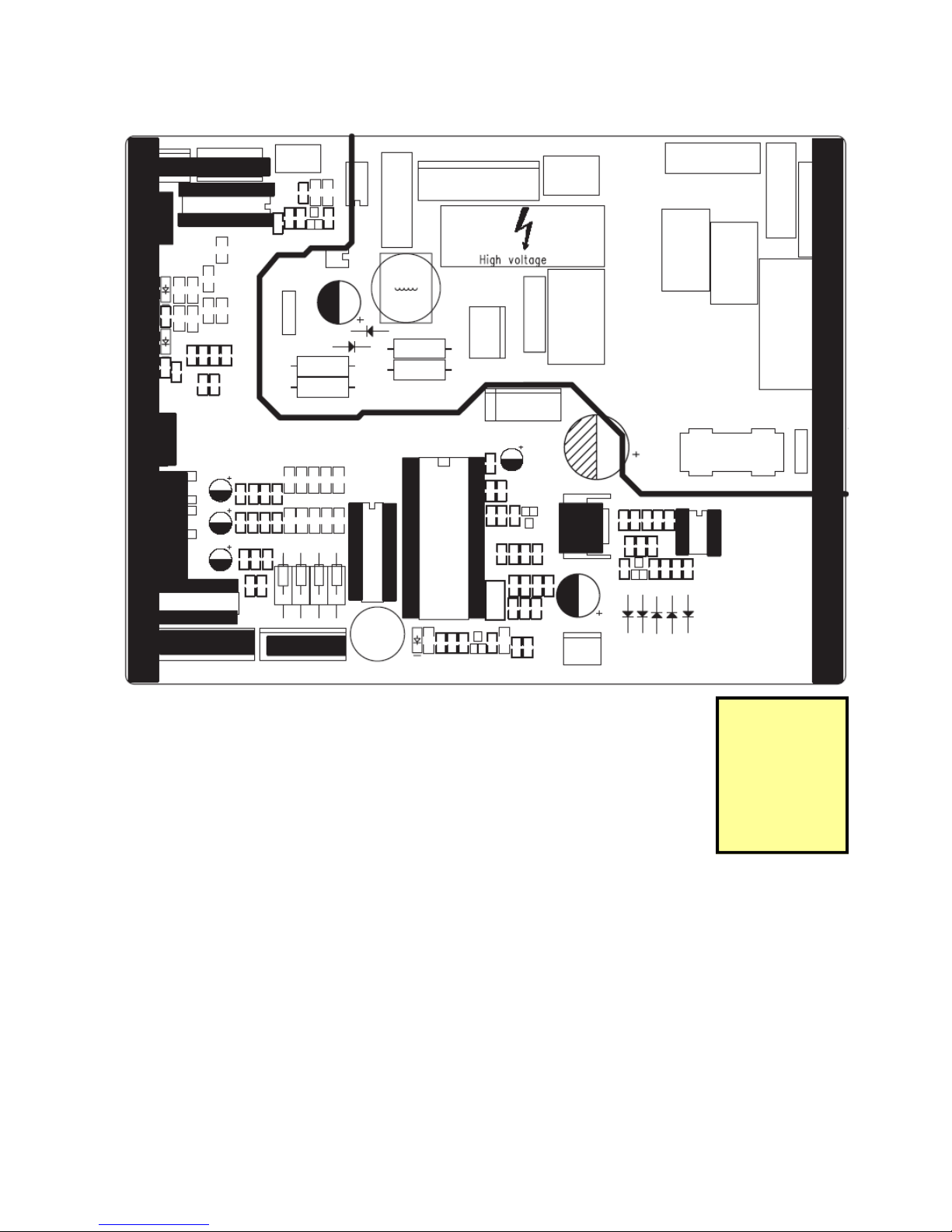
Printed Circuit Board (bottom-view)
Left Right
Down
Up
Do not modify
electrical com-
ponents or
wiring, for
replacements
only use OEM
spare-parts!
GREE Service Manual GWC09AA / K5NNA6A Page 26
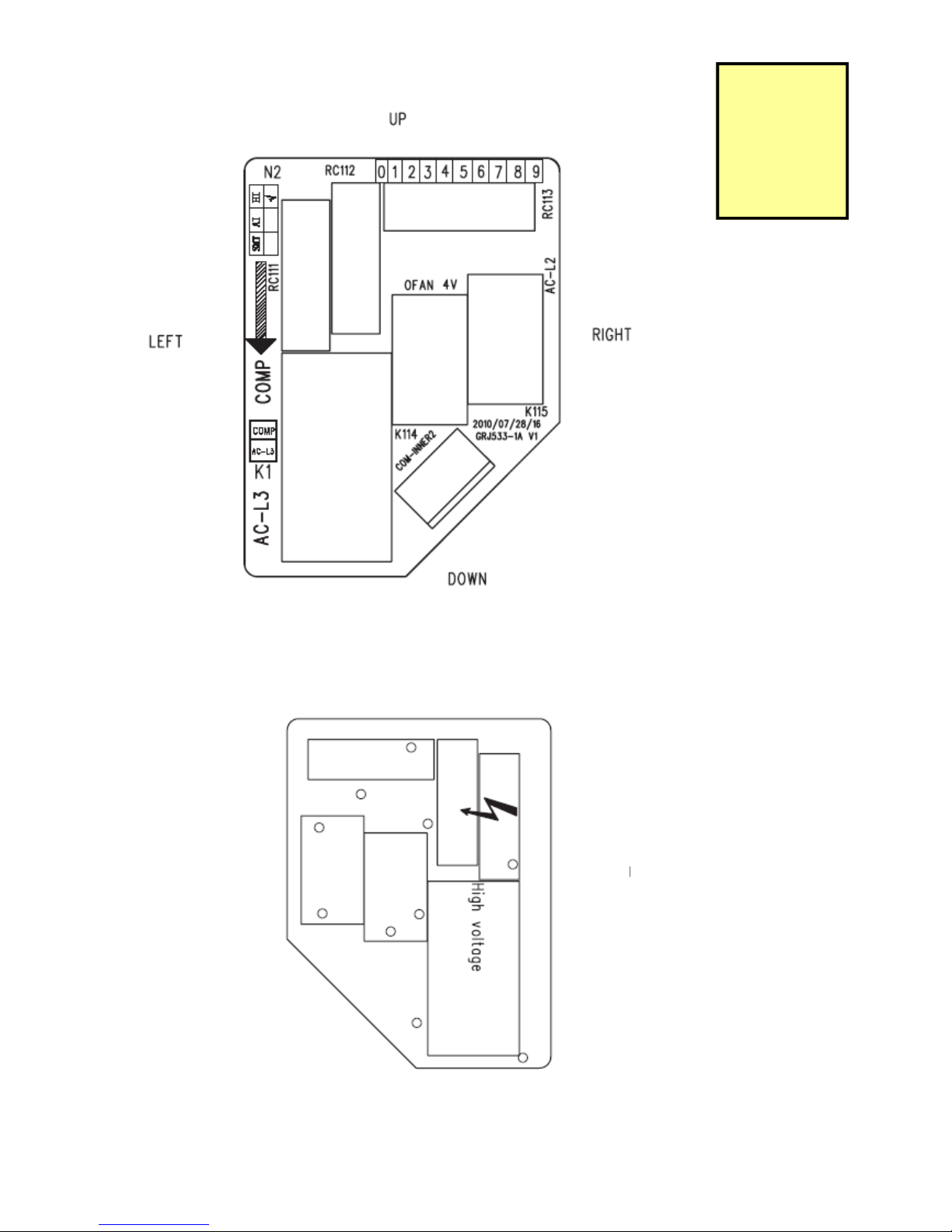
Relay Box (top-view)
Relay Box (bottom-view)
Down
Up
Left
Right
Do not modify
electrical com-
ponents or
wiring, for
replacements
only use OEM
spare-parts!

GREE Service Manual GWC09AA / K5NNA6A Page 27
Functional description and controls
The remote control
GREE Service Manual GWC09AA / K5NNA6A Page 28
GREE Service Manual GWC09AA / K5NNA6A Page 29
Unit Functions
GREE Service Manual GWC09AA / K5NNA6A Page 30
Battery
Replacement
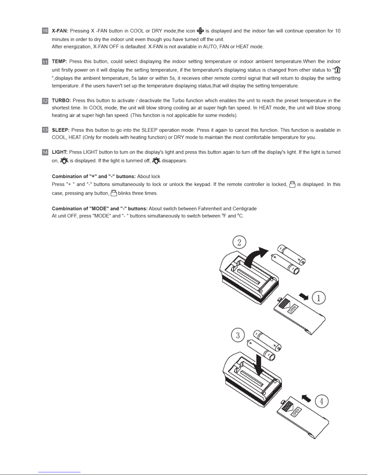
Replacement of batteries:
1: Remove the battery cover plate from the rear of the
remote controller.
2: Take off the used batteries
3: Insert two new AAA1.5V batteries and pay attention
to the polarity.
4: Reinstall the battery cover plate.
Please notice:
When replacing the batteries, do not use used or different types of batteries, otherwise it may cause malfunction.
If the remote controller will not be used for a long time,
please remove batteries to avoid leaking.
Make sure that used batteries are disposed of according
to local regulations. Most often batteries are not allowed
to be part of domestic waste.
If the remote controller does not operate correctly,
please take the batteries out and reinsert them after at
least 30 seconds. If the malfunction is still valid, replace
the batteries.
 Loading...