

Gree GVH24AK-K3DNC8A Service Manual

’
Service Manual
Change for life
GREE ELECTRIC APPLIANCES, INC. OF ZHUHAI
Model:
GVH24AK-K3DNC8A
(Refrigerant:R410A)

Service Manual
Table of Contents
Part
Ⅰ
: Technical Information
.......................................................................1
1.Summary
.......................................................................................................................1
2. Specications
..........................................................................................................2
2.1 Specication Sheet ...........................................................................................................2
2.2 Operation Characteristic Curve ........................................................................................4
2.3 Capacity Curve in Different Outdoor Temperature ...........................................................4
2.4 Cooling Data Sheet in Rated Frequency ..........................................................................5
2.5 Noise Curve ......................................................................................................................5
3. Outline Dimension Diagram
........................................................................6
3.1 Indoor Unit ........................................................................................................................6
3.2 Outdoor Unit .....................................................................................................................7
4. Refrigerant System Diagram
......................................................................8
5. Electrical Part
...........................................................................................................9
5.1 Wiring Diagram .................................................................................................................9
5.2 PCB Printed Diagram ..................................................................................................... 11
6. Function and Control
......................................................................................13
6.1 Function Buttons of Air Conditioner ................................................................................13
6.2 Remote Control Operations ............................................................................................15
6.3 GREE+ App Operation Manual ......................................................................................20
6.4 Ewpe Smart App Operation Manual ...............................................................................21
6.5 Description of Each Control Operation ...........................................................................22
Part
Ⅱ
: Installation and Maintenance
.................................................28
7. Notes for Installation and Maintenance
..........................................28
8. Installation
................................................................................................................31
8.1 Installation procedures ...................................................................................................31
8.2 Installation Parts-checking ............................................................................................32
8.3 Selection of Installation Location ....................................................................................32
8.4 Precautions of Connecting Pipe .....................................................................................32
8.5 Electric Connection Requirement ...................................................................................33
8.6 Installation of Indoor Unit ................................................................................................34
8.7 Installation of Outdoor Unit .............................................................................................36
8.8 Vacuum Pumping and Leak Detection ...........................................................................37
8.9 Check after Installation and Test Operation ...................................................................37
8.10 Installation of anti-tilting Chain .....................................................................................37
Table of Contents

Service Manual
9.Troubleshooting
....................................................................................................39
9.1 Judgement by Flashing LED of Indoor ...........................................................................39
9.2 How to Check Simply the Main Part of Indoor ...............................................................43
9.3 How to Check Simply the Main Part of outdoor .............................................................52
9.4 Maintenance Method for Normal Malfunction .................................................................61
10. Exploded View and Parts List
..............................................................63
10.1 Indoor Unit ....................................................................................................................63
10.2 Outdoor Unit .................................................................................................................66
11. Removal Procedure
.......................................................................................68
11.1 Removal Procedure of Indoor Unit ...............................................................................68
11.2 Removal Procedure of Outdoor Unit ............................................................................77
Appendix:
........................................................................................................................82
Appendix 1: Reference Sheet of Celsius and Fahrenheit ....................................................82
Appendix 2: Conguration of Connection Pipe .....................................................................82
Appendix 3: Pipe Expanding Method ...................................................................................83
Appendix 4: List of Resistance for Temperature Sensor ......................................................84
Table of Contents
Service Manual
1
Technical Information
1.Summary
Part
Ⅰ
: Technical Information
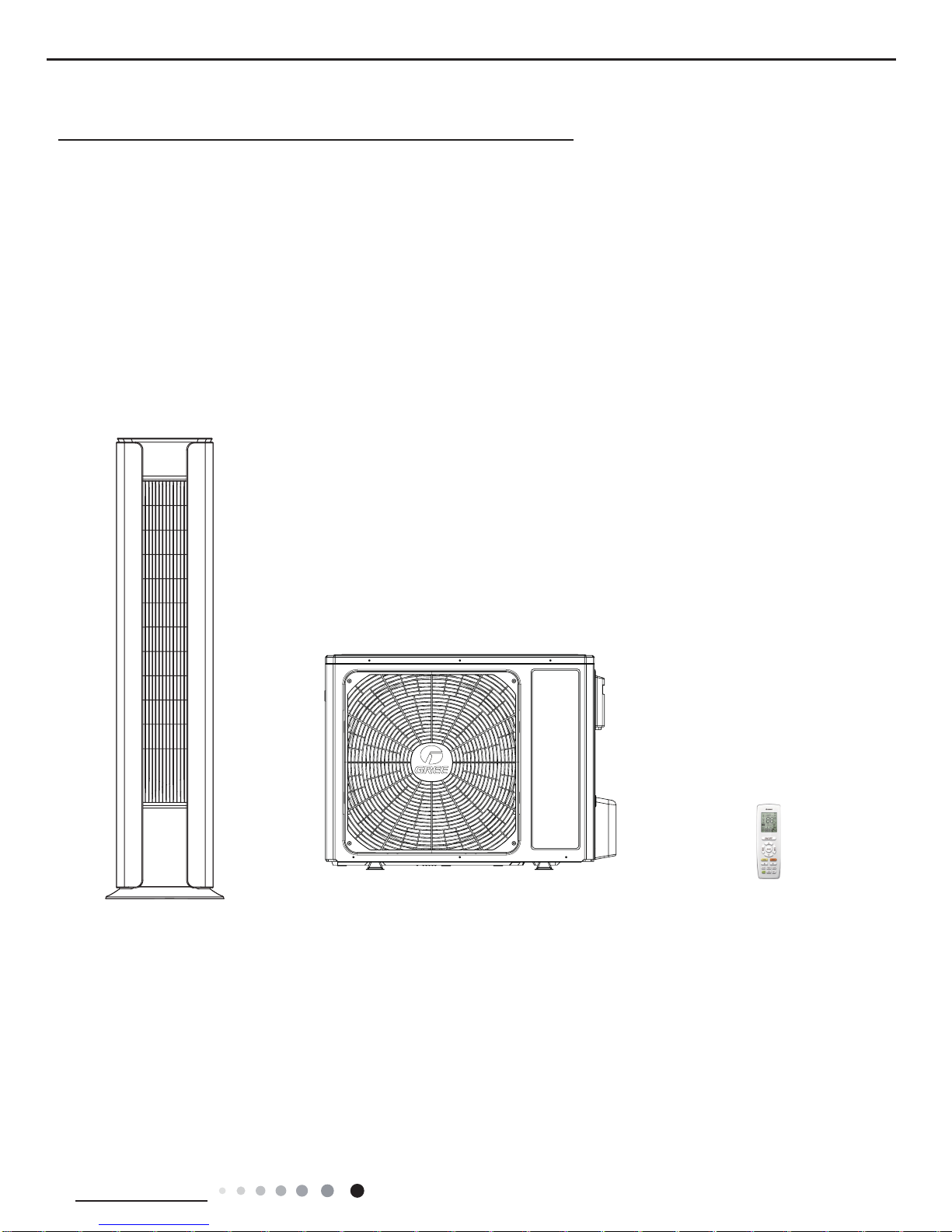
Indoor Unit:
Remote Controller:
Outdoor Unit:
GVH24AK-K3DNC8A/I
GVH24AK-K3DNC8A/O
YAP1F4(WiFi)
Service Manual
2
Technical Information
2. Specications
2.1 Specication Sheet
Parameter Unit Value
Model GVH24AK-K3DNC8A
Product Code CH057000100
Power
Supply
Rated Voltage V~ 220-240
Rated Frequency Hz 50/60
Phases 1
Power Supply Mode Outdoor
Cooling Capacity W 7100
Heating Capacity W 8800
Cooling Power Input W 2220
Heating Power Input W 2750
Cooling Power Current A 10.46
Heating Power Current A 13.03
Rated Input W 3800
Rated Cooling Current
A 21.00
Rated Heating Current A 22.00
Air Flow Volume(SH/H/M/L/SL) m3/h 1480/1200/1060/750/570
Dehumidifying Volume L/h 3.0
EER W/W 3.20
COP W/W 3.20
SEER W/W /
HSPF W/W /
Application Area m
2
46-70
Indoor Unit
Model of indoor unit GVH24AK-K3DNC8A/I
Product Code CH057N00100
Fan Type Centrifugal
Diameter Length(DXL) mm Φ111.5X1959
Fan Motor Cooling Speed(SH/H/M/L/SL) r/min 1250/1020/900/780/480
Fan Motor Heating Speed(SH/H/M/L/SL) r/min 1250/1020/900/780/480
Output of Fan Motor W 30
Fan Motor RLA A 0.12
Fan Motor Capacitor μF /
Evaporator Form Aluminum Fin-copper Tube
Pipe Diameter mm Φ5
Row-n Gap mm 2-1.3
Coil Length (LXDXW) mm 952X23X369
Swing Motor Model MP35GD/MP35GT/MP50AC
Output of Swing Motor W 2.5/2.5/3.5
Fuse A 5
Sound Pressure Level (SH/H/M/L/SL) dB (A) 47/42/39/35/30
Sound Power Level (SH/H/M/L/SL) dB (A) 61/56/53/49/44
Dimension (WXHXD) mm 458X1790X458
Dimension of Carton Box (LXWXH) mm 1940X555X575
Dimension of Package(LXWXH) mm 1943X558X590
Net Weight kg 50
Gross Weight kg 55
Service Manual
3
Technical Information
The above data is subject to change without notice; please refer to the nameplate of the unit.
Outdoor Unit
Model of Outdoor Unit GVH24AK-K3DNC8A/O
Product Code CH057W00100
Compressor Manufacturer/Trademark ZHUHAI LANDA COMPRESSOR CO., LTD.
Compressor Model QXFS-D25zX090H
Compressor Oil FW68DA
Compressor Type Rotary
Compressor RLA A 10.63
Compressor Power Input W 2366
Overload Protector HPC115/95U1
Throttling Method Electron expansion valve +Capillary
Operation Temp ºC 16~30
Ambient Temp (Cooling) ºC -15~43
Ambient Temp (Heating) ºC -20~24
Condenser Form Aluminum Fin-copper Tube
Pipe Diameter mm Φ7
Rows-n Gap mm 2-1.4
Coil Length (LXDXW) mm 980X790X427
Fan Motor Speed rpm 750
Output of Fan Motor W 60
Fan Motor RLA A 0.87
Fan Motor Capacitor μF /
Air Flow Volume of Outdoor Unit m3/h 4000
Fan Type Axial-ow
Fan Diameter mm Φ520
Defrosting Method Automatic Defrosting
Climate Type T1
Isolation I
Moisture Protection IPX4
Permissible Excessive Operating
Pressure for the Discharge Side
MPa 4.3
Permissible Excessive Operating
Pressure for the Suction Side
MPa 2.5
Sound Pressure Level (H/M/L) dB (A) 57/-/-
Sound Power Level (H/M/L) dB (A) 67/-/-
Dimension (WXHXD) mm 955X700X396
Dimension of Carton Box (LXWXH) mm 1026X455X735
Dimension of Package(LXWXH) mm 1029X458X750
Net Weight kg 54
Gross Weight kg 58
Refrigerant R410A
Refrigerant Charge kg 2.0
Connection
Pipe
Length m 5
Gas Additional Charge g/m 50
Outer Diameter Liquid Pipe mm Φ6
Outer Diameter Gas Pipe mm Φ16
Max Distance Height m 20
Max Distance Length m 30
Note: The connection pipe applies metric diameter.
Service Manual
4
Technical Information
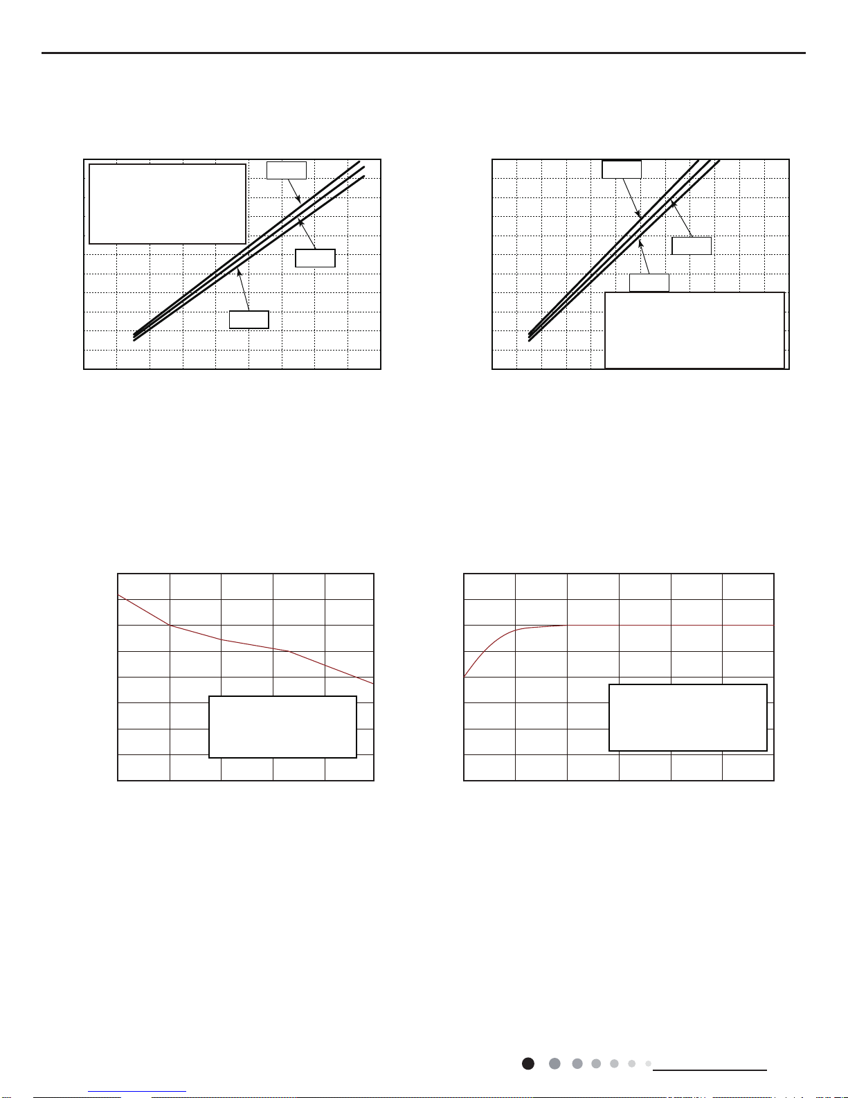
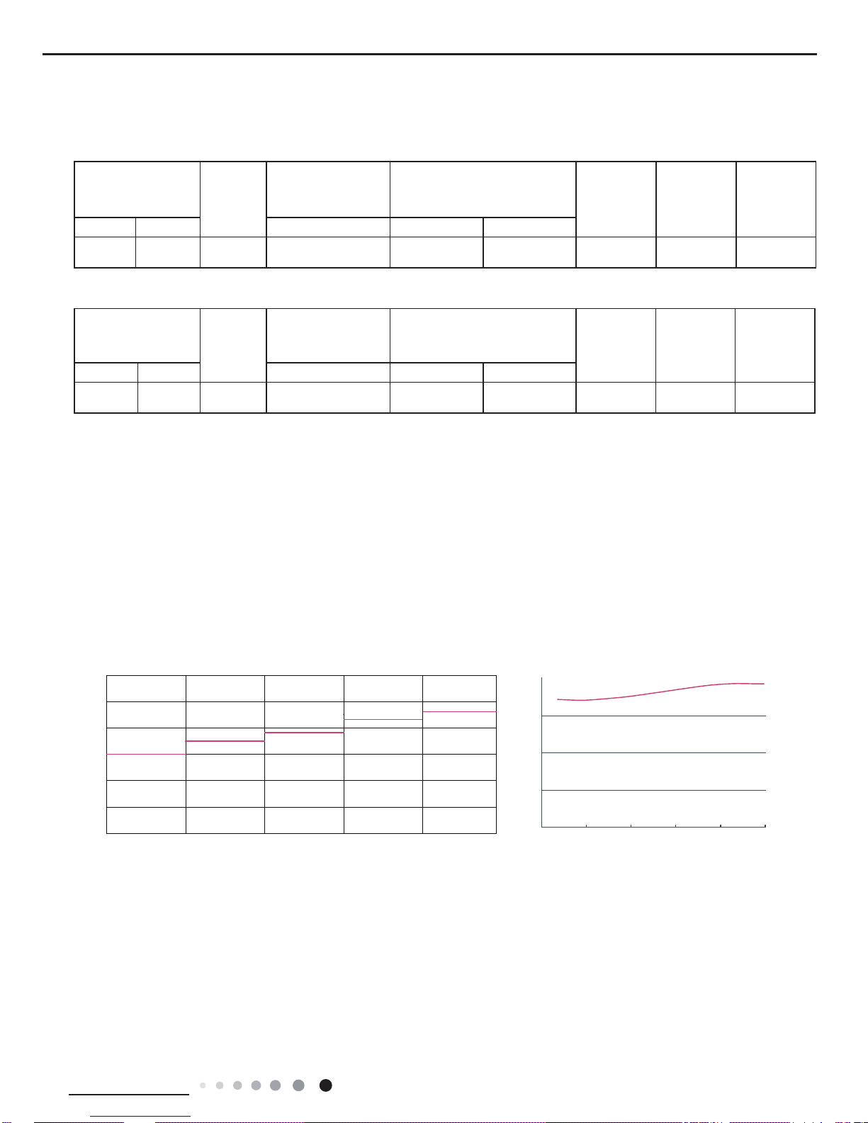
2.2 Operation Characteristic Curve
2.3 Capacity Curve in Different Outdoor Temperature
Cooling Heating
Capacity ratio(%)
Capacity ratio(%)
29 34 39 44 49 54
60
70
80
90
100
110
120
50
40
40
50
120
110
100
90
80
70
60
108-07-20
-30 -15
Conditions
Indoor: DB20°C/WB15°C
Indoor air flow: High
Pipe length: 5m
Conditions
Indoor: DB27°C/WB19°C
Indoor air flow: High
Pipe length: 5m
Cooling Heating
01020304050607090
0110210010908070605040302010
80
11
10
9
8
7
6
5
4
3
2
1
0
11
10
9
8
7
6
5
4
3
2
1
0
220V
230V
240V
220V
230V
240V
Current (A)
Current (A)
Conditions
Indoor:DB27°C/WB19°C
Outdoor:DB35°C/WB24°C
Indoor air flow:Super High
Pipe length:5m
Conditions
Indoor:DB20°C/WB15°C
Outdoor:DB7°C/WB6°C
Indoor air flow:Super High
Pipe length:5m
Compressor speed (rps)
Compressor speed (rps)
Service Manual
5
Technical Information
2.4 Cooling Data Sheet in Rated Frequency
Instruction:
T1: Inlet and outlet pipe temperature of evaporator
T2: Inlet and outlet pipe temperature of condenser
P: Pressure at the side of big valve
Connection pipe length: 5 m.
Rated cooling
condition(°C) (DB/WB)
Model
Pressure of gas pipe
connecting indoor and
outdoor unit
Inlet and outlet pipe temperature
of heat exchanger
Fan speed of
indoor unit
Fan speed of
outdoor unit
Compressor
revolution
(rps)
Indoor Outdoor P (MPa) T1 (°C) T2 (°C)
27/19 35/24 24K 0.8 to 1.0
in:8~11
out:11~14
in:75~85
out:37~43
Super High High 89
Rated heating
condition(°C) (DB/WB)
Model
Pressure of gas pipe
connecting indoor and
outdoor unit
Inlet and outlet pipe temperature
of heat exchanger
Fan speed of
indoor unit
Fan speed of
outdoor unit
Compressor
revolution
(rps)
Indoor Outdoor P (MPa) T1 (°C) T2 (°C)
20/- 7/6 24K 2.5 to 2.7
in:75~85
out:37~43
in:1~3
out:3~5
Super High High 87
Cooling:
Heating:
2.5 Noise Curve
60
60
60 80
100
50
50
40
40
40
30
30
20
20
20
10
0
0
Noise/dB(A)
low low
Middle
High Super Super High
)A(Bd/esioN
Indoor side noise when blowing
Indoor fan motor rotating speed
Compressor frequency/Hz
Outdoor side noise when blowing
Service Manual
6
Technical Information
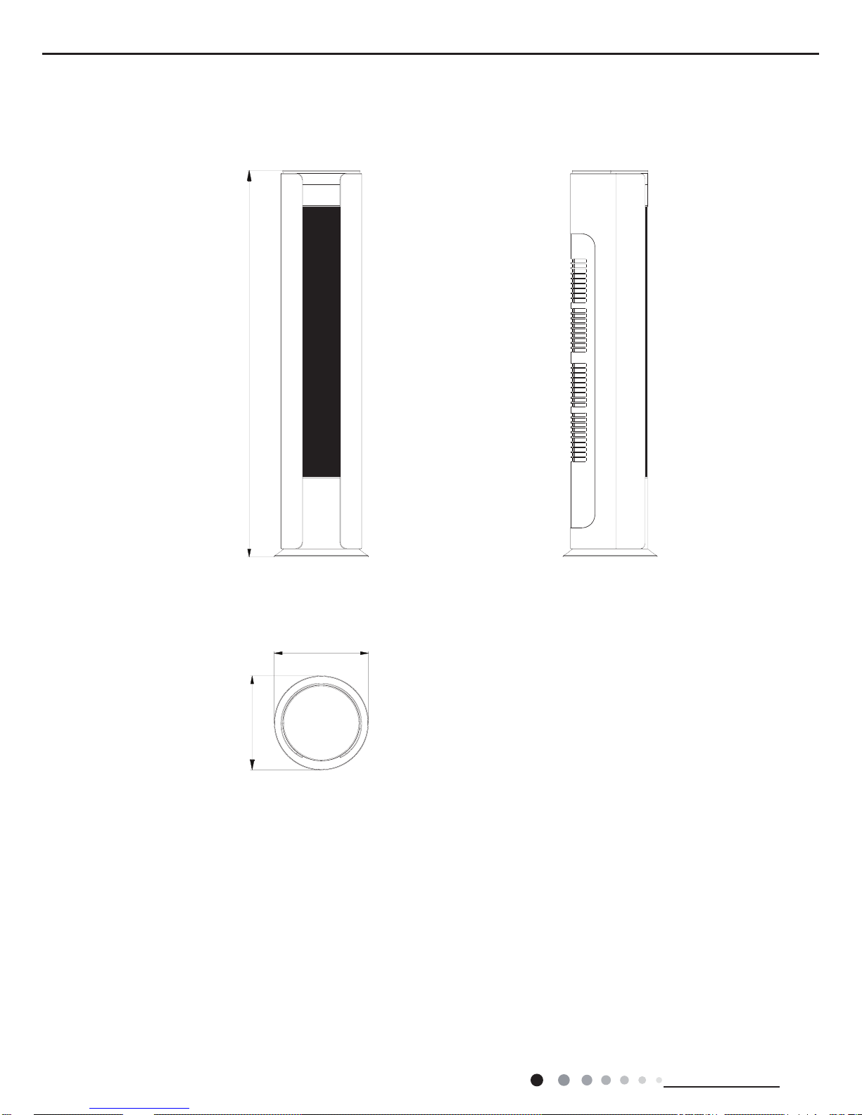
3. Outline Dimension Diagram
3.1 Indoor Unit
Unit:mm
458
4581790
476
Service Manual
7
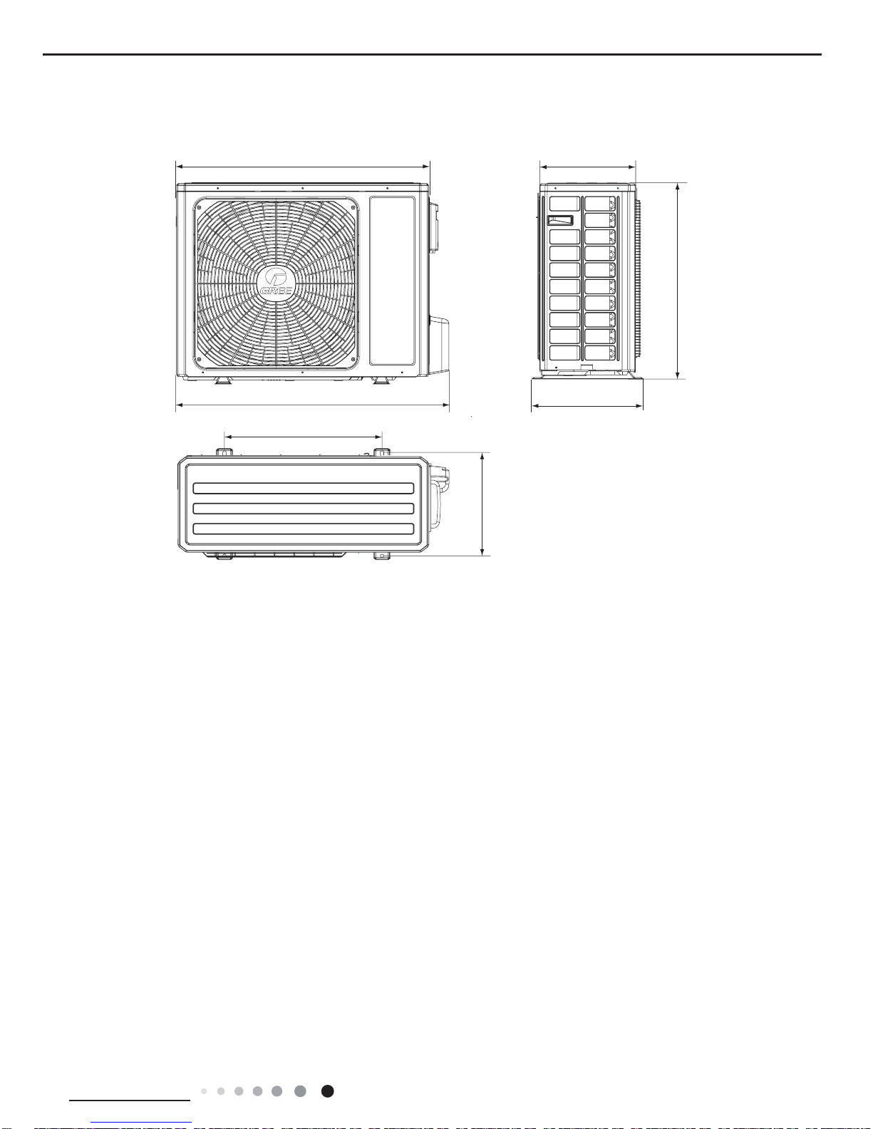
Technical Information
3.2 Outdoor Unit
Unit:mm
897
340
560
463
963
396
007
Service Manual
8
Technical Information
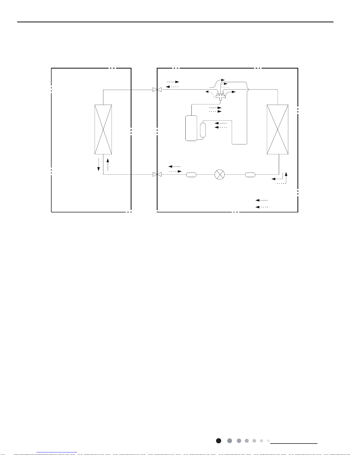
4. Refrigerant System Diagram
Connection pipe specication:
Liquid : 1/4" (6 mm)
Gas : 5/8" (16mm)
Indoor unit
Outdoor unit
Indoor unit
Outdoor unit
COOLING
HEATING
Accumlator
4-Way valve
COOLING
Discharge
Suction
Discharge
Suction
Heat
exchanger
(evaporator)
Heat
exchanger
(evaporator)
Heat
exchanger
(condenser)
Valve
Valve
Valve
Valve
Liquid pipe
side
Gas pipe
side
Liquid pipe
side
Gas pipe
side
Compressor
Strainer
StrainerElectronic
expansion
Strainer
Capillary
Service Manual
9
Technical Information
5. Electrical Part
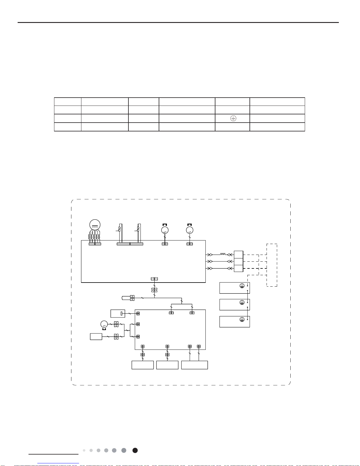
5.1 Wiring Diagram
●
Indoor Unit
● Instruction
Symbol Symbol Color Symbol Symbol Color Symbol Name
YE Yellow BN Brown COMP Compressor
RD Red BU Blue Grounding wire
YEGN Yellow/Green BK Black / /
;
,1&+,1*6:,7&+
;
728&+6:,7&+
3+272(/(&75,&
;
)&
6:,1*/5
&21'8&7,9(
&1&1
0
&1
$3φ',63/$<%2$5'
;;
;
:,),
$3
/()75,*+7
67(302725
6:,7&+
),/0
&21'8&7,9(
),/0
&1 &1
$3φ',63/$<
02'8/(
:,),02'8/(
$3
$30$,1%2$5'
&20',63/$<
%8
%.
%.
%8
1
;7
1
%1
%1
287'22581,7
57
5220
7(03
&20287
$&/
6:,1*8' 6:,1*8'
0
)$102725
'&02725
0
76(1625
6(1625 6(1625
7(03
78%(
67(3
83'2:1
<(*1
<(*1
3(
-81&7,21%2;
<(*1
7(50,1$/
%/2&.
3(
(/(&75,&%2;
3(
(9$325$725
57
0
02725
67(3
83'2:1
02725
/
/
0$*1(7,&
5,1*
0$*1(7,&
5,1*
600007060219
Service Manual
10
Technical Information
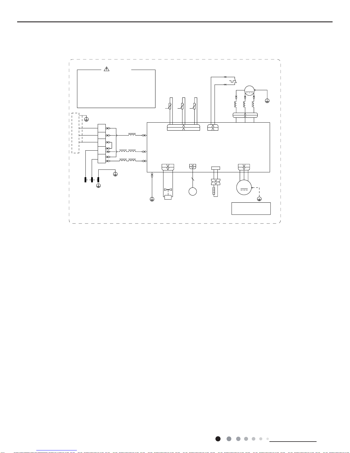
● Outdoor Unit
These wiring diagrams are subject to change without notice; please refer to the one supplied with the unit.
3OHDVHGRQWWRXFKDQ\
HOHFWURQLFFRPSRQHQWRU
WHUPLQDOZKHQWKHPDFKLQHLV
UXQQLQJVWRSSLQJRUKDV
EHHQSRZHUHGRIIIRUOHVV
WKDQPLQXWHVWRSUHYHQW
WKHULVNRIHOHFWULFVKRFN
:$51,1*
&20,11(5
1
$&B/
1/
<(*1
%8
3(
1
/
1
%1
%.
%8
;7
,1'22581,7
5,1*
%1
%8
%/2&.
7(50,1$/
0$*1(7,&
32:(5
%1%.
76(1625
&203
:
9
8
35,17('&,5&8,7%2$5'
3(
<(*1
)$102725
:$< 2)$1)$
7979
9$/9(
<9
:$<
0
3(
(.9
(OHFWURQLF
([SDQVLRQ
9DOYH
3(
<(*1
3(
5,1*
0$*1(7,&
29(5/2$'3527(&725
<(*1
:5'9<(8%8
8%(<
5'
3(
3(
57 57 57
5'
29&&203
+:+:
6$7
&203
;
8%(<
:+ %.
7(036(1625
28778%(
2875220
7(036(1625
(;+$867
7(036(1625
$3
...
<(*1
3(
/
/
%8
%1
%.
/
/ /
/
LURQVKHOOPRWRU
RQO\DSSOLHVWRWKH
127(0RWRUJURXQG
/
/
5'
%$1'
+($7(5
%27720
5'
(+
+($7%
60000700094303
Service Manual
11
Technical Information
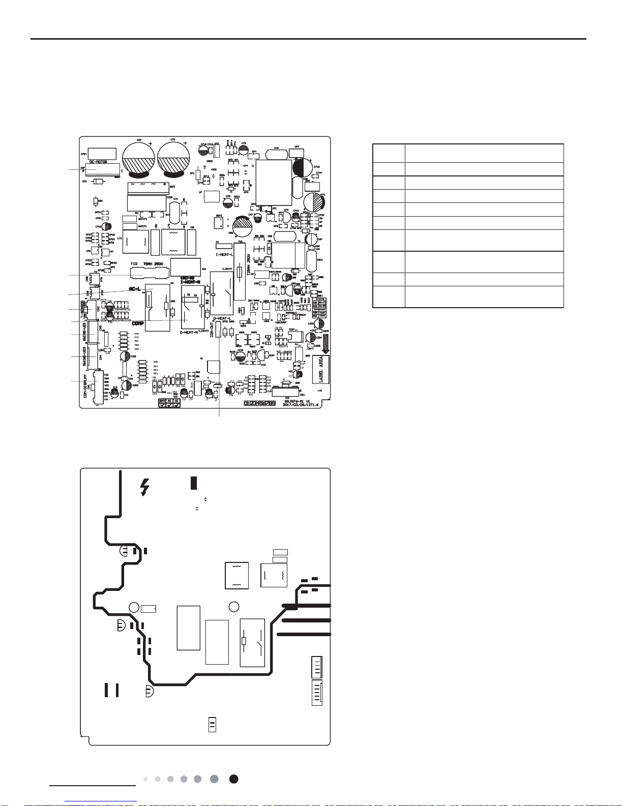
5.2 PCB Printed Diagram
● Top view
Indoor unit
● Bottom view
NO. Name
1 Wiring terminal for DC motor
2 Fuse
3 Live wire
4 Neutral wire
5 temperature sensor interface
6
Interface of up and down
swing terminal (up)
7
Interface of up and down
swing terminal (down)
8 Interface of display
9
Interface of outdoor unit
communication
1
2
3
5
4
6
7
8
9
Service Manual
12
Technical Information
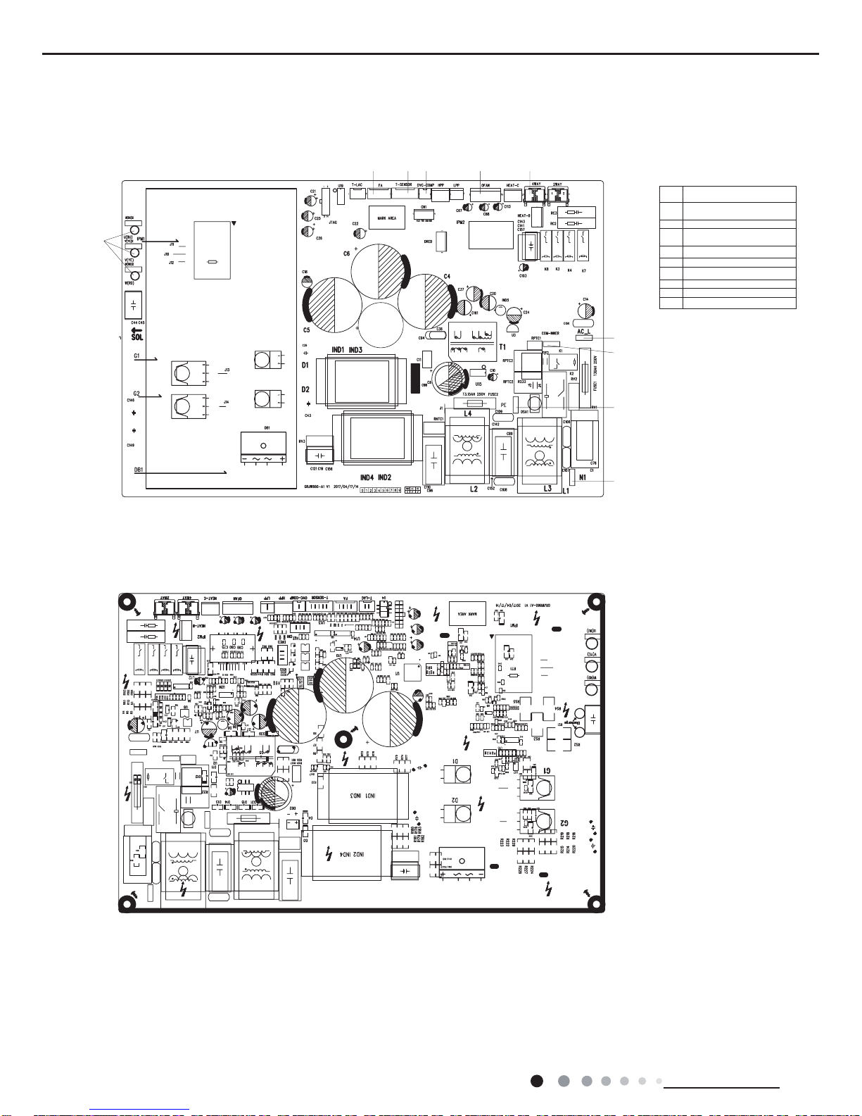
Outdoor unit
● Top view
● Bottom view
1
23456
7
8
9
10
1
Terminal of compressor
wire
2
Terminal of electronic
expansion valve
3Terminal of sensor
4
Terminal of compressor
overload protection
5
6
Terminal of outdoor fan
7
8
Terminal of 4-way valve
9
Power supply live wire
10
Communication wire with
indoor unit
Earthing wire
Power supply neutral wire
Service Manual
13
Technical Information
6. Function and Control
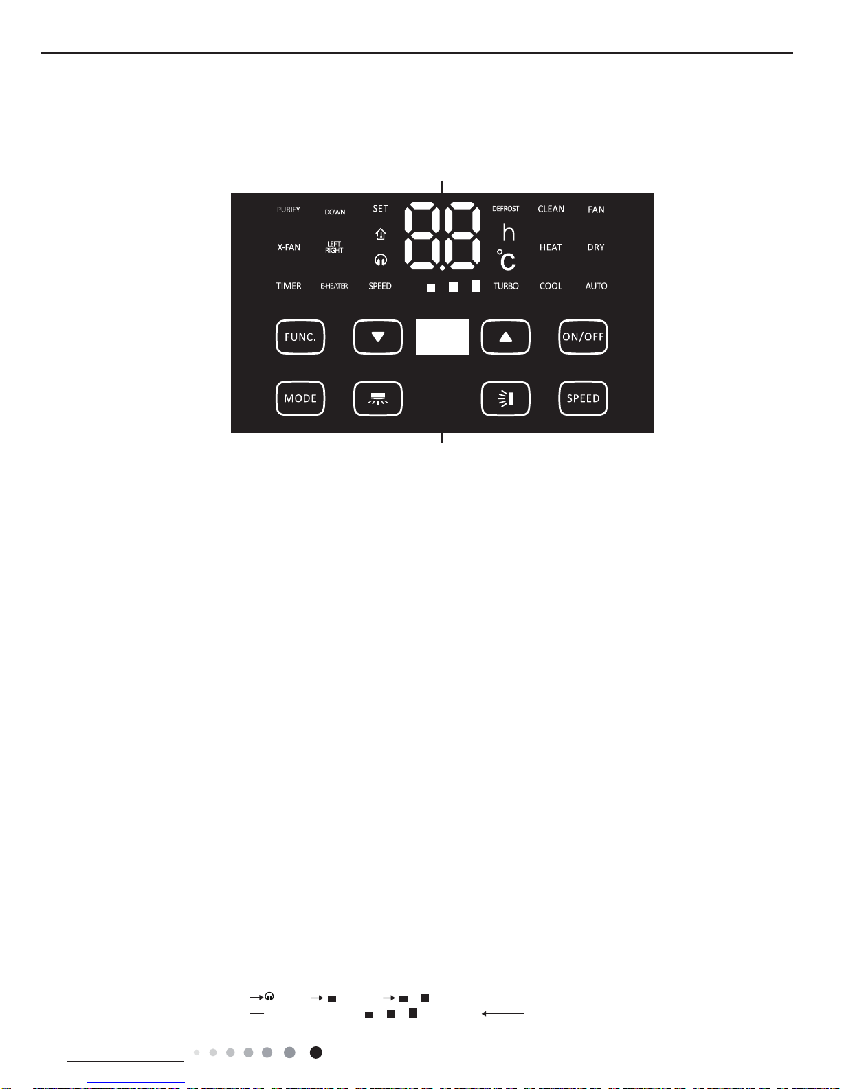
6.1 Function Buttons of Air Conditioner
Display
Button
UP
Function button
● When selecting the function by function button, if the unit is not turned off and it hasn’t get the remote control signal within 2min,
press function button and then it will circulate from the previous set function. 2min later or when turning off the unit or the unit has get
the remote control signal, press the function button and it will circulate from the rst icon.
● Clean function: This function is not available under on status. Under off status, press “function” button until clean icon is ashing.
Press ▼ or ▲ button to enter into clean function. At this time, the case starts rotating until the lter is rotated to he front side of air
conditioner.
Press button to turn off the clean function and the unit will exit from the clean status. The main body will rotate to the reset position.
After entering into clean function:
A. When pressing ON/OFF button, it will exit from the clean function and the unit will start operation;
B. When pressing function button, if clean icon is ashing, it indicates clean function can be canceled. The case will rotate to the
reset position and the complete unit stays under standby status.
● Under on status, when each pressing of function button, it will set and change in the sequence of X-fan, timer, purify (not available
for this model), set and room temperature. When certain characters are ashing, it indicates this function can be set. Press ▼ or
▲ button to set it. It there’s no operation within 5s after setting, the setting is conrmed. Or press function button can also conrm
the setting.
● Under X-fan status, press function button to turn off the unit directly. Under off status and X-fan is not set, when each pressing
function button, it can switch between timer and clean setting. When certain characters are ashing, it indicates this function can
be set.● Press ▼ or ▲ button to set it. It there’s no operation within 5s after setting, the setting is conrmed. Or press function
button can also conrm the setting.
Mode button
● Press this button continuously and the mode will change circularly among “cool →dry→fan→heat (not available for this cooling
only air conditioner)→auto”. (Note: Cooling only unit won’t accept heating operation signal. For cooling only unit, pressing MODE
button under FAN mode will skip heating mode and enter cooling mode.)
▼ and ▲ buttons
● After pressing ▼ or ▲ button for once, the set temperature will increase or decrease 1℃. The temperature range is 16℃~30℃.
This button is invalid under auto mode. Timer setting can be adjusted within the range of 0~24h.
● When pressing ▼ and ▲ buttons simultaneously for consecutive 3s, the air con- ditioner will display “LC”, which indicates buttons
are locked. It’s invalid when pressing any buttons under on status or pressing ON/OFF button and function button under off status.
When press ▼ and ▲ buttons simultaneously for con- secutive 3s again, lock will be released.
1.ON/OFF button
● This button is used for turning on or turning off the uit.
(Note: Under X-fan operation, pressure ON/OFF button will turn on the unit directly.)
2.Speed button
Press this button and the fan speed will be selected and displayed according to below method:
Მ
(Quiet)
(Medium)
Turbo
(High)
(Low)
Service Manual
14
Technical Information
● Quiet and turbo can be set by pressing fan button under cool and heat mode.
● Fan speed is defaulted at low fan speed and it can’t be adjusted under dry mode.
button.
● This button is turned for turning on or turning off the up&down swing.
button
● This button is turned for turning on or turning off the left&right swing.
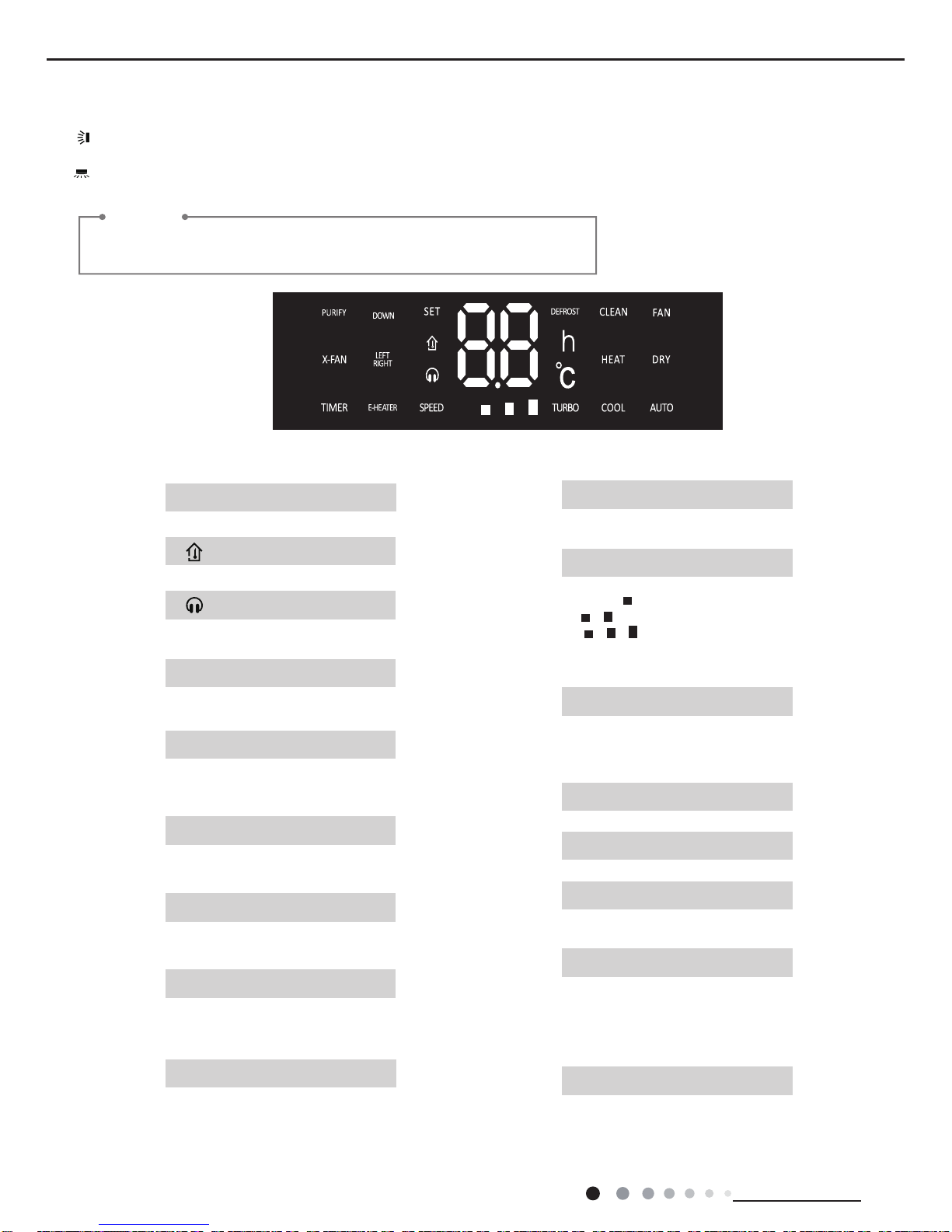
The buttons for this series model adopt touch buttons. This series model
without purification function and
Reminder
e-heater function.
ƽ
Display set temperature.
Display indoor ambient temperature.
ƽ
SET
ƽ
When the characters are bright, it indicates the clean function is turned on.
CLEAN
ƽ
When the characters are bright, it indicates the fan function is turned on.
FAN
ƽ
When this characters are bright, it indicates the purification function is
turned on (this function is not available
for this series model)
PURIFY
ƽ
ƽ
Display up&down swing status.
UP & DOWN
Display left&right swing status.
LEFT & RIGHT
ƽ
When the characters are bright, it indicates the X-fan function is turned on.
X-FAN
ƽ
When the characters are bright, it indicates the E-heater function is turned
on.
E-HEATER
ƽ
When the characters are bright, it in-
this series model)
dicates the timer function is turned on.
TIMER
ƽ
When the characters of “SPEED” are
bright, “ ” indicates low fan speed;
“ ” indicates medium fan speed;
“ ” indicates high fan speed.
“TURBO” indicates turbo fan.
Under auto fan speed, the accrual
target fan speed is displayed.
SPEED & TURBO
When the characters are bright, it indicates the cool mode is turned on.
ƽ
COOL
When the characters are bright, it indicates the heat mode is turned on.
ƽ
HEAT
When the characters are bright, it indicates the dry mode is turned on.
ƽ
DRY
When the characters are bright, it indicates the auto mode is turned on.
ƽ
AUTO
When the characters are bright, it indicates the defrosting function is
turned on.
ƽ
DEFROST
When the characters are bright, it indicates the quiet function is turned on.
ƽ
UP
(this function is not available for
Service Manual
15
Technical Information
6.2 Remote Control Operations
This is a general use remote controller, it could be used for the air conditioners with multifunction; For some function, which the
model doesn't have, if press the corresponding button on the remote controller that the unit will keep the original running status.
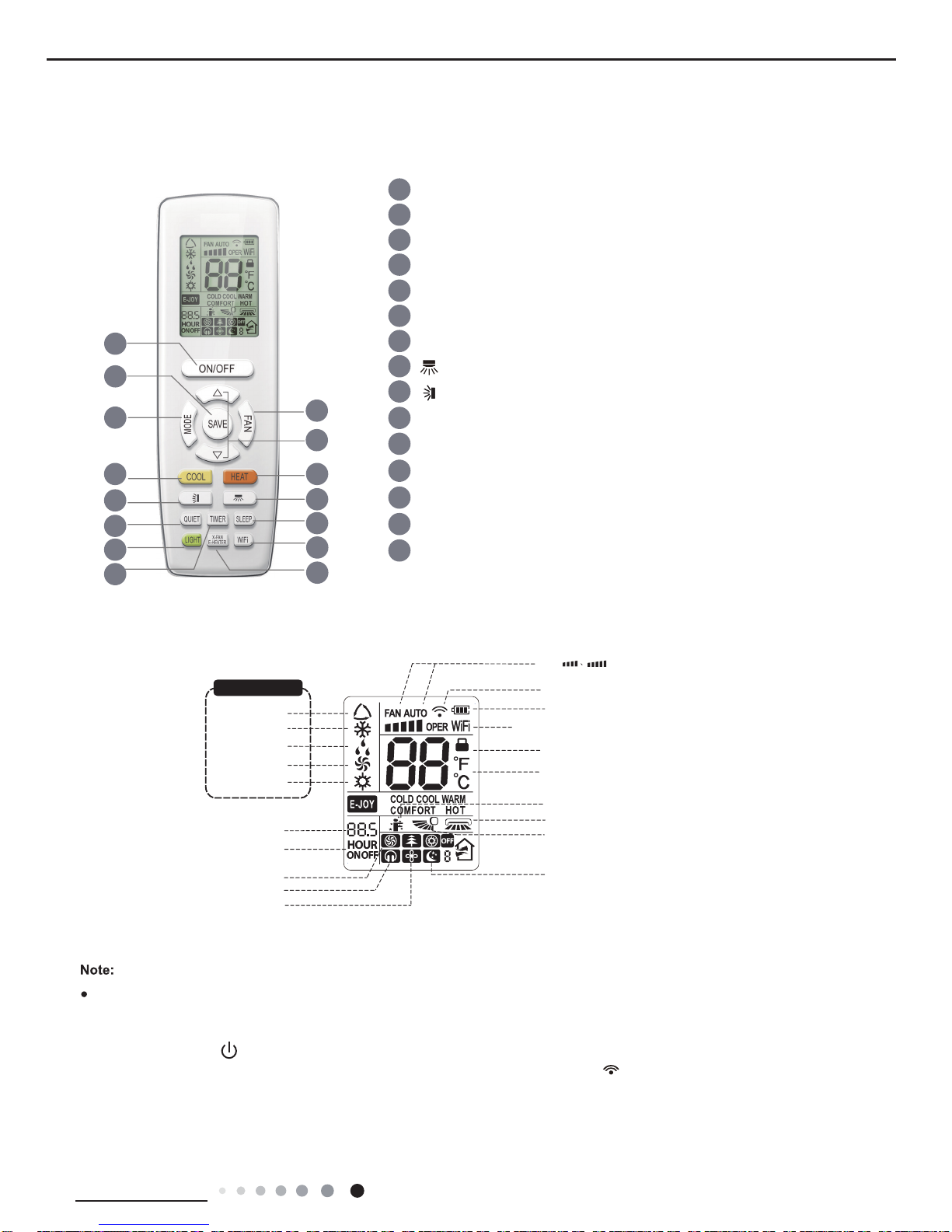
Buttons on remote controller
Introduction for icons on display screen
6
3
7
9
10
14
15
13
12
8
11
5
4
2
1
X-FAN function
Turbo fan speed
Quiet mode
Set fan speed
(No fan speed. It’s displayed
only after turning it on.)
{
Send signal
Switch temperature displaying type on
the unit’s display
Set time
TIMER ON/TIMER OFF
Child lock
Up & down swing
Left & right swing
battery power
Heat mode
Fan mode
Dry mode
Cool mode
Auto mode
Operation mode
I feel function
Sleep mode
WiFi
This is a general remote controller.Some
models have this function while some
do not. Please refer to the actual models.
{
1 ON/OFF button
2 SAVE button
3 FAN button
4 MODE button
6
button
7
button
9
COOL button
14
LIGHT button
15
TIMER button
12
SLEEP button
13
QUIET button
10
HEAT button
8
X-FAN/E-HEATER button
11
WiFi button
5 ▲/ button
▲
Introduction for buttons on remote controller
●
After putting through the power, the air conditioner will give out a sound.
Operation indictor " " is ON.
After that, you can operate the air conditioner by using remote controller.
●
Under on status, pressing the button on the remote controller, the signal icon " "
on the display of remote controller will
blink once and the air conditioner will give out a “di” sound, which means the signal has been sent to the air conditione
r.
Service Manual
16
Technical Information
ON/OFF button
1
SAVE button
2
Press this button can turn on or turn off the air conditioner. After turning on the air conditioner, indoor unit will give out a sound.
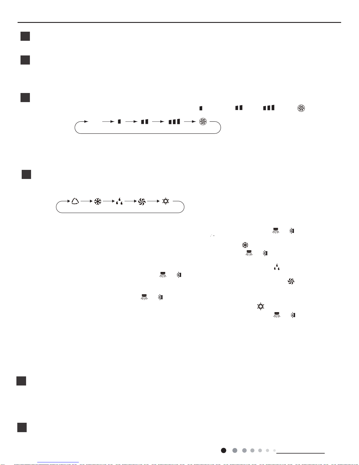
FAN button
3
Pressing this button can set fan speed circularly as: auto (AUTO), low( ), medium
( ), high( ), turbo( ).
Auto
● It’s Low fan speed under Dry mode.
● Turbo cannot be set in FAN mode.
● Under AUTO speed, air conditioner will select proper fan speed automatically according to ex-factory setting.
Note:
Under cooling mode, press this button to start up or turn off energy-saving function.When energy-saving function is started up,
"SE" will be shown on remote controller, and air conditioner will adjust the set temperature automatically according to
ex-factory setting to reach to the best energy-saving effect. Press this button again to exit energy-saving function.
▲
▲/ button
5
● Press "▲" or " " button once increase or decrease set temperature 1ć(°F). Holding "▲" or " " button, 2s later,
set temperature on remote controller will change quickly . On releasing button after setting is finished, temperature indicator
on indoor unit will change accordingly. (T emperature can’t be adjusted under
▲
▲
▲
● When setting TIMER ON, TIMER OFF, press "▲" or " " button to adjust time. (Refer to TIMER button for details)
auto mode)
● When selecting auto mode, air conditioner will operate automatically according to the sensed temperature. Set temperature
can’t be adjusted and will not be
displayed as well. Press "F
AN" button can adjust fan speed. Press " " / " " button can adjust
fan blowing angle.
● After selecting cool mode, air conditioner will operate under cool mode. Cool
indicator " " on indoor unit is ON. Press "▲"
or " "
FAN" button to adjust fan speed. Press " " / " " button
to adjust
fan blowing angle.
unit is ON.
● When selecting dry mode, the air conditioner operates at low speed under dry
mode. Dry indicator " " on indoor unit is ON.
Under dry mode, fan speed can’t
be adjusted. Press " " / " " button to adjust fan blowing angle.
● When selecting fan mode, the air conditioner will only blow fan, no cooling and
no heating. Fan indicator " " on indoor
Press "FAN" button to adjust fan speed. Press" " / " " button to adjust fan blowing angle.
● When selecting heating mode, the air conditioner operates under heat mode.
Heat indicator " " on indoor unit is ON.
" button to adjust set temperature. Press "FAN" button to adjust fan speed. Press " " / " " button to
adjust fan blowing angle. (Cooling only unit won’t receive heating mode signal. If setting heat mode with remote controller,
press ON/OFF button can’t start up the unit).
MODE button
▲
Press "▲" or "
▲
4
Press this button to select your required operation mode.
AUTO COOL FANDRYHEAT
Note:
● For preventing cold air, after starting up heating mode, indoor unit will delay 1~5 minutes to blow air (actual delay time is
● Set temperature range from remote controller: 16~30
ć
(61-86°F);
Fan speed: auto, low speed, medium speed, high speed,
turbo speed.
button to adjust set temperature. Press "
depend on indoorambient temperature).
Cool button
6
● Press this button, unit will operate in cool mode.
Service Manual
17
Technical Information
● Under simple swing mode, pres this button can turn on (" " icon is displayed) or
turn off (" " icon is not displayed)
● When the unit is turned off by remote controller, press "▲" button and " "
● This remote controller is the general type remote controller. When remote controller receives the signal of " " , sw
ing
status is same as " " ; when remote controller receives " " , swing status is same as left&right swing OFF.
button can switch between single swing mode
" " on the remote controller will flash twice.
9
Under fixed-angle swing mode, press this button and then left&right swing status will
circulate as shown in the right figure:
● Under simple swing mode, pres this button can turn on (" " icon is displayed)
lor turn off (" " icon is not displayed) the
● When the unit is turned off by remote controller, press "▲" button and " "
button can switch between single swing mode and
" " on the remote controller will flash twice.
Under fixed-angle swing mode, press this button and
the up&down swing status will circulate as shown in the right figure:
button
8
button
no display
no display
10
SLEEP button
Under COOL, or HEAT mode, press this button to start up sleep function.
" " icon is displayed on remote controller
. Press this
button again to cancel sleep function and " " icon will disappear.After powered on, Sleep Off is defaulted. After the unit is
turned off, the Sleep function is canceled. In this mode, the time of time can be adjusted. Under Fan
DRY and Auto modes,
this function is not available.
WiFi button
11
● This function is only available for some models.
Press " WiFi " button to turn on or turn off WiFi function. When WiFi function is turned on, the " WiFi " icon will be displayed on
remote controller; Under status of remote controller off, press "MODE" and " WiFi " buttons simultaneously for 1s,WiFi module
will restore to factory default setting.
12
Pressing this button in COOL or DRY mode, the icon " " is displayed and the
Only under cooling mode and dry mode, press this button can turn on (characters
(characters of “X-FAN” are not displayed)
of “X-FAN” are displayed) or turn off
X-FAN function.
indoor fan will continue operation for a few
minutes in order to dry the indoor unit even though you have turned off the unit. After energization, X-FAN OFF is
defaulted.X-FAN is not available in AUTO, FAN or HEAT mode.
unit will be blowed
This function indicates that moisture on evaporator of indoor
after the unit is stopped to avoid mould.
● Having set XFAN function on: After turning off the unit by pressing ON/OFF
about a few minutes. at low speed.
button indoor fan will continue running for
In this period, press X-FAN button to stop indoor fan directly.
●
●
Under heating mode, press this button and the E-HEATER status will changed circularly as below:
●
Having set XFAN function off: After turning off the unit by pressing ON/OFF
button, the complete unit will be off directly.
X-FAN/E-HEATER button
Auto E-HEATER (no display)
E-HEATER OFF
( is displayed)
E-HEATER ON
( is displayed)
the left&right swing function.
and fixed-angle swing mode.
up&down swing function.
fixed-angle swing mode.
Service Manual
18
Technical Information
LIGHT button
14
Press this button to turn off display light on indoor unit. Press this button again to turn on display light.
●
This function is not available for this unit.
Press this button can turn on or turn off QUIET function.
13
QUIET button
Note:
● Time setting range: 0.5-24 hours.
● Time interval between two operations can’t exceed 5s. Otherwise, remote controller will exit the setting status automatically.
hour. When holding " " or " " button, 2s later, the time will change quickly until to
Cancel TIMER OFF: Press "TIMER" button again under TIMER OFF status.
● At OFF status, press this button once can set TIMER ON. Please refer to TIMER off for detailed operation.
Cancel TIMER ON: Press "TIMER" button again under TIMER ON status.
TIMER button
15
●
At ON status, press this button once can set TIMER OFF. The character of HOUR
TIMER
ON. After each pressing of " " or " " button, time will increase or
decrease half an
▲
▲
▲
▲
▲
▲
Function introduction for combination buttons
Child lock function
Press "▲" and " " simultaneously to turn on or turn off child lock function. When
on remote controller. If you operate
the remote controller, the " " icon will blink three times without sending signal to the unit.
▲
child lock function is on, " " icon is displayed
Temperature display switchover function
Under OFF status, press " " and "MODE" buttons simultaneously to switch temperature display between ć and .
▲
1.
After putting through the power, press "ON/OFF" button on remote controller to turn on the air conditioner.
2.
Press "MODE" button to select your required mode: AUTO, COOL, DRY, FAN, HEAT.
3.
Press "▲" or " " button to set your required temperature. (Temperature can’t be adjusted under auto mode).
4.
Press "FAN" button to set your required fan speed: auto, low speed, medium speed, high speed, turbo speed.
Operation guide
▲
Replacement of batteries in remote controller
5.
Press " " button to select fan blowing angle.
1. Lift the cover along the direction of arrow (as shown in Fig 1 ǐ).
2. Take out the original batteries (as shown in Fig 1 Ǒ).
3. Place two 7# (AAA 1.5V) dry batteries, and make sure the position of “+”
polar and “-” polar is correct (as shown in Fig 2
ǒ).
4. Reinstall the cover (as shown in Fig 2 Ǔ).
Fig.1 Fig.2

Service Manual
19
Technical Information
● During operation, point the remote control signal sender at the receiving window on indoor unit.
● The distance between signal sender and receiving window should be no
obstacles between them.
more than 8m, and there should be no
● Signal may be interfered easily in the room where there is fluorescent lamp
should be close to indoor unit during
or wireless telephone; remote controller
operation.
● Replace new batteries of the same model when replacement is required.
● When you don’t use remote controller for a long time, please take out the batteries.
● If the display on remote controller is fuzzy or there’s no display, please replace batteries.
NOTICE
Service Manual
20
Technical Information
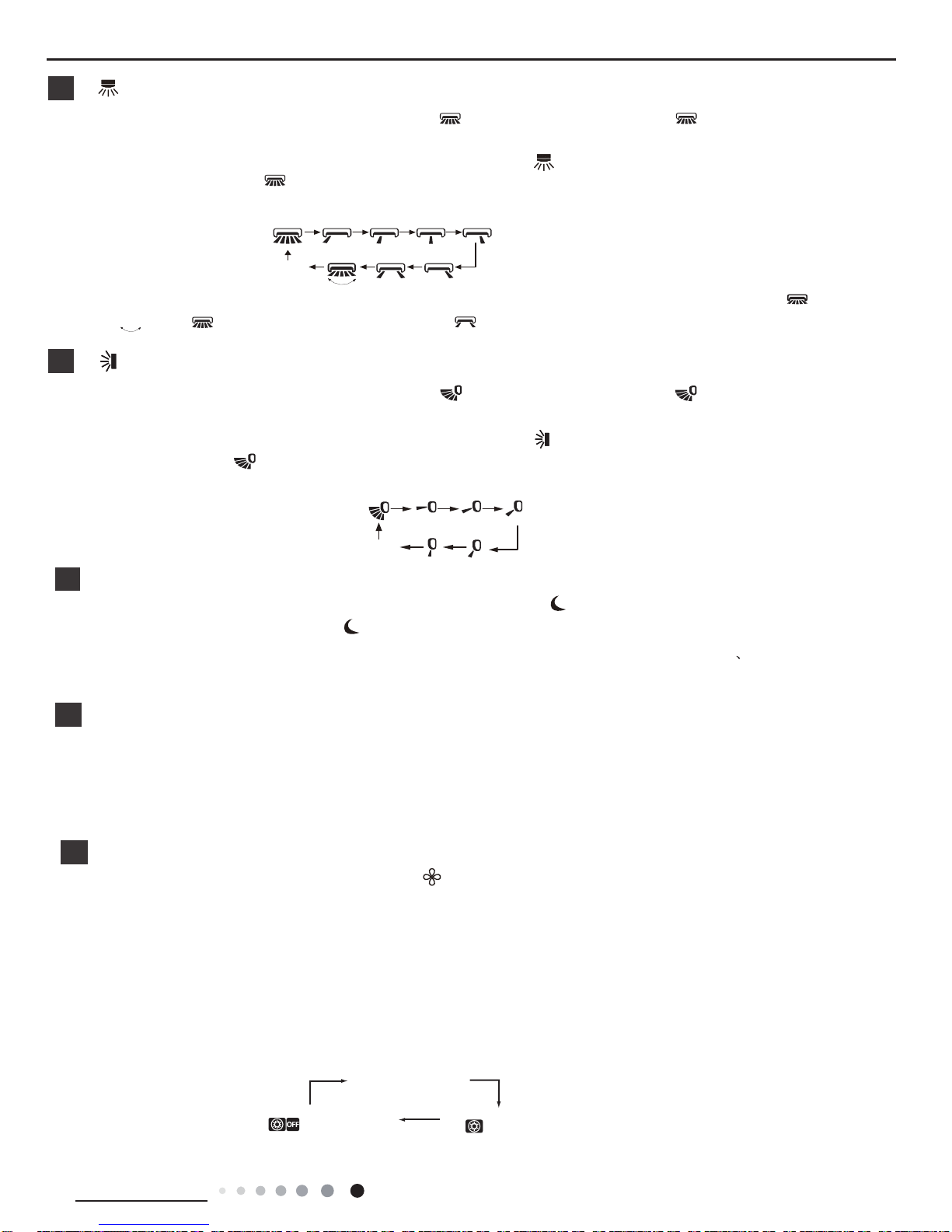
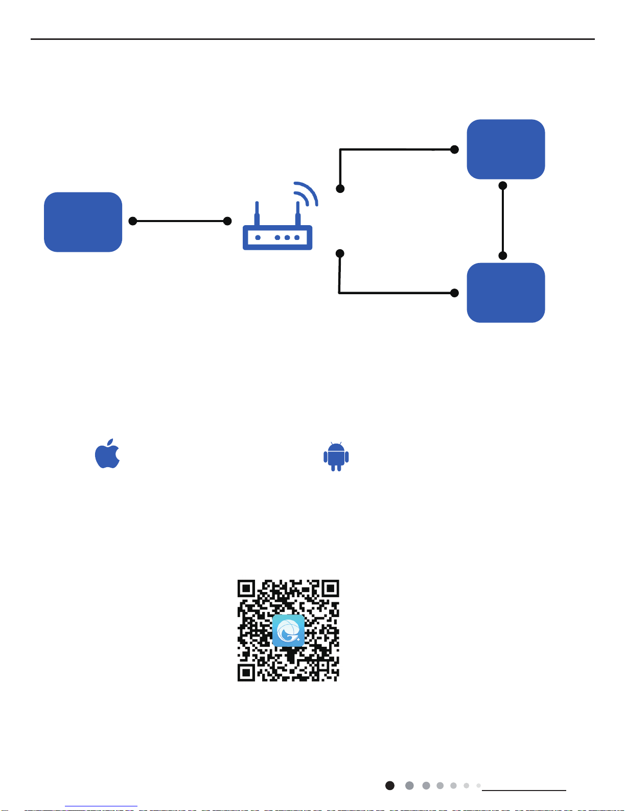
6.3 GREE+ App Operation Manual
Control Flow Chart
Download and installation
Operating Systems
Requirement for User's smart phone:
Scan the QR code or search "GREE+" in the application market to download and install it. When "GREE+" App is installed, register the
account and add the device to achieve long-distance control and LAN control of Gree smart home appliances.
For more information, please refer to "Help" in App.
Internet
Cellular/
Other Wi-FI
Home Wi-Fi
Home wireless router
Home Wi-Fi
Gree
Gree Cloud
GREE+ APP
intelligent
home
appliances
iOS system
Support iOS7.0 and
above version
Android system
Support Android 4.4
and
above version
GREE+ App Download Linkage
Service Manual
21
Technical Information
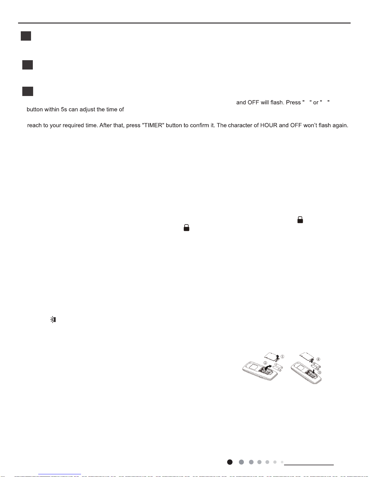
Control Flow Chart
Download and installation
Operating Systems
Requirement for User's smart phone:
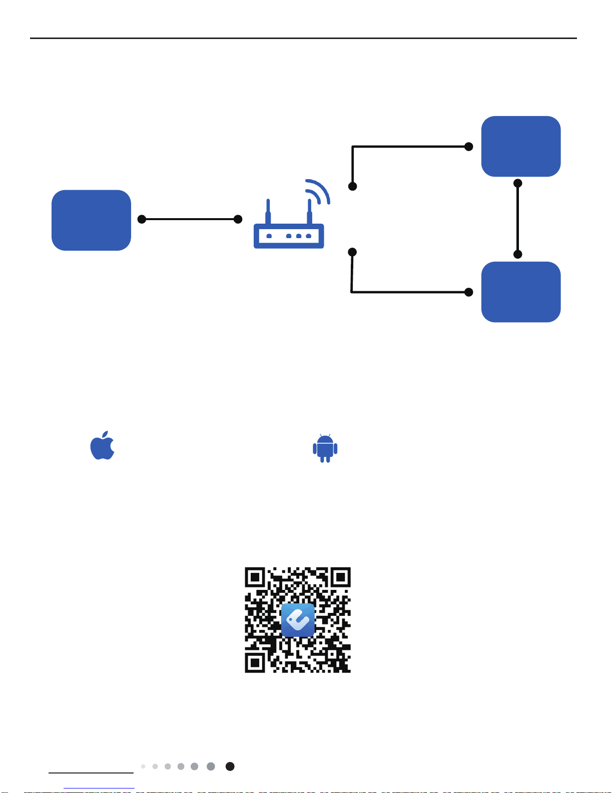
Scan the QR code or search "Ewpe Smart" in the application market to download and install it. When "Ewpe Smart" App is installed,
register the account and add the device to achieve long-distance control and LAN control of smart home appliances.
For more information, please refer to "Help" in App.
6.4 Ewpe Smart App Operation Manual
iOS system
Support iOS7.0 and
above version
Android system
Support Android 4.4
and
above version
App Download Linkage
Internet
Cellular/
Other Wi-FI
Home Wi-Fi
Home wireless router
Home Wi-Fi
Cloud
APP
intelligent
home
appliances

Service Manual
22
Technical Information
6.5 Description of Each Control Operation
Indoor units
Mode and Operation Introduction
Basic fu nctions
1. Cooling Mode
Under this mode, the fan and louver should be operated according to the setting status. The temperature setting range is
16~30℃, and the initial value is 25℃. In case of malfunction of outdoor unit or protection shutdown, indoor unit will maintain
the original operation status and display malfunction indication.
2. Drying Mode
Under this mode, the fan operates under low speed, and the louver operates under setting status. The temperature setting
range is 16~30℃, and the initial value is 25℃. In case of malfunction of outdoor unit or protection shutdown, indoor unit will
maintain the original operation status and display malfunction indication.
3. Heating Mode
Under this mode, the temperature setting range is 16~30℃, and the initial value is 25℃. The working condition and process
of heating: If the compressor status sent by outdoor unit is on, indoor unit operates according to the cold air prevention
condition; if the compressor status sent by outdoor unit is off, indoor unit operates according to the waste heat blow condition.
On under heating mode, indoor fan operates according to the waste heat blow condition. Defrosting control: indoor unit
receives drying signal of outdoor unit and displays drying icon ―drying‖. De-energize it to heat, and indoor fan will stop running
after 10s.
4. Fan mode
Under this mode, the fan of indoor unit can choose high, medium, low or auto fan speed
5. Auto mode
Under this mode, operation is based on the following conditions according to the ambient temperature. When Tamb.>26℃,
unit will operate in cooling mode and indoor set temperature is 26℃; When 20℃≤Tamb.≤26℃, unit will operate in drying
mode and indoor set temperature is 24℃; When Tamb. <20℃, unit will operate in heating mode, and indoor set temperature
is 20℃, when Tamb.≥24℃, unit will exit the heating mode. For cooling only unit, when Tamb. <20℃, it will operate in fan mode
and indoor set temperature is 20℃; when Tamb.≥24℃, unit will exit the fan mode.
Other f unctions
1. Swing function
Different models have different swing functions. For up & down swing, left & right swing, swing angle is different according to
different structures and motors. It is designed to meet users’ needs for comfort air swing.
2. Turbo
Under cooling and heating mode, turbo function can be controlled by remote controller or button (Turbo function is not
available in auto, drying, or fan mode); when turbo is set, the indoor fan will operate in turbo fan speed.
3. X-fan
When unit is turned on in cooling or drying mode (X-fan is not available in auto, drying, or fan mode), X-fan can be set on or
off. When X-fan is on, after unit is turned off by the on/off button, indoor fan will operate at low speed for 10 minutes (air swing
will maintain original status for 10 minutes while other loads are turned off). After that, the entire unit will be shut off. When
X-fan is off, after unit is turned off by the on/off button, the entire unit will be shut off.
4. Timer
Use remote controller or button to set timer on or off. The setting range is 0.5~24 hours.
5. Sleep
①
. If controller is in cooling or drying mode, at the start of sleep function, T preset will be raised no more than 3℃, and then
unit will operate according to the temperature raised.
②
.If controller is in heating mode, at the start of sleep function, T preset will be decreased no more than 3℃, and then unit will
operate according to the temperature decreased.
6. Buzzer
When controller is just energized or receives effective button signal, buzzer will sound.
7. Cleaning
This function is excluded when the unit is turned on. Turn off the unit and press function button to select ―cleaning‖ with its

Service Manual
23
Technical Information
icon ashing. Then press ―set +‖ or ―set –‖ to conrm the selection, and the ―cleaning‖ icon will be lighted up. The case of the
unit will start rotating until the lter rotates to the front of the air conditioner. Cut off the power supply to detach and clean the
lter. If you don’t want to detach the lter while clean function is enabled, press the function button to select ―cleaning‖ with its
icon ashing. Then press ―set +‖ or ―set –‖ until the ―cleaning‖ icon goes off. Unit will then exit the cleaning function and its
case will rotate back to the shut-off position.
8. Forced operation function of indoor unit Enter into forced operation control:
Within 5 minutes after unit is energized, continuously press Lights-off button of the remote controller for 3 times in 3 seconds,
then unit enters into uorine collecting mode and displays Fo. It will send the uorine collecting mode for 25 minutes. Each
load will be treated according to the status when unit is turned on in cooling mode (the set fan speed is high fan speed and set
temperature is 16°C). Exit from forced operation control: After receiving any remote control signal or button signal, unit will
exit from the uorine collecting mode and operate according to current orders set; or after operating for 25 minutes, unit will
exit the uorine collecting mode and be shut down automatically.
9. Display
9.1 Functions
When auto, drying, fan, timer, purifying, setting, room-temperature or cleaning function is selected, the corresponding icon on
the display will start ashing. Once the function is on or off, the icon will stop ashing and the enabled function will be
displayed. (The low-end units are without air exchange and health functions)
9.2 Middle numeric part
9.2.1 If there is malfunction protection, it only displays malfunction codes;
9.2.2 During normal operation, if there is any button or remote control signal for set temperature or timer, it displays relevant
setting and then displays set temperature (set or room temperature) after 5 seconds.
9.3 Mode part
There are auto, cooling, drying, fan and heating modes. If you choose any of them, the corresponding icon and characters will
be displayed. Under auto mode, unit will display auto and the actual operation mode.
9.4 Indicator control
When turning on the unit, the operation indicator will be lighted up.
9.5 Buttons display
When unit is powered on and under standby status, on/off button will be on while other buttons are off. By this time, press
on/off button to turn on the unit directly. Press any other buttons and then all buttons are on. After turning on the unit, the
buttons except on/off button and other displaying icons are controlled by the Light button of remoter controller. If lights are
turned off, pressing any of the buttons except on/off button can light up all the buttons. When buttons are concealed, slightly
press the button area and then all buttons will be displayed. When buttons are displayed, the relevant operations can be
conducted. If there is no button operation, buttons will be concealed after displaying for 10 seconds.
10. Buttons
There are on/off button, cooling button, heating button, function button, + button, -button, fan speed button, left&right, up
&down buttons on the panel.
10.1 On/Off button
This button controls on/off of controller. Every time you press, on/off status shift once. Note: During X-fan operation, pressing
on/off button will turn on the unit directly.
10.2 Cooling button
When unit is turned on, press this button to enter into cooling mode.
10.3 Heating button
When unit is turned on, press this button to enter into heating mode.
10.4 Set – and set +
10.4.1 If you are not setting functions, every time you press set + button or set - button, the set temperature rises or
decreases by 1℃. The adjustment range is 16℃~30℃. Buttons are invalid under auto mode.
10.4.2
If you are setting functions, press these buttons to select a certain function repeatedly.
Service Manual
24
Installation and Maintenance
10.4.3 After simultaneously pressing + button and – button for continuously 3 seconds, all buttons on display board will be
shielded. Later if you press any of the buttons, the buzzer will sound once while the dual-8 will display “LC” for three times and
then return to normal display to indicate the user that the button has been locked. When pressing these two buttons
simultaneously again, the shielding function will be canceled and display will resume normal status.
10.5 Function button
When unit is turned on, functions of auto, drying, fan, timer, purifying, setting and room temperature setting can be shifted
orderly. If any of the character ashes, it means this function can be set by pressing set +, set -. During X-fan operation, press
this button to turn off the unit directly. When unit is off and not under X-fan status, press function button to directly set timer on.
When unit is off and not under X-fan status, every time you press function button, timer and cleaning can be shifted orderly. If
any of the character ashes, it means the corresponding function can be set by pressing set +, set -. Conrmation is made if
there is no operation changed within 5 seconds after setting is done.
10.6 Fan speed button
(Under drying and auto drying, this button is invalid and buzzer does not sound.) When pressing fan speed button, the fan
speed can be chosen and displayed according to the following order:
Outdoor units
1. Compensatory function of input parameter
Under cooling mode, the indoor ambient temperature of control calculation participated =T indoor amb.
-⊿
T cooling indoor
amb. compensation
)
Under heating mode, the indoor ambient temperature of control calculation participated =T indoor amb.
-⊿
T heating indoor
amb. compensation
)
2.In order to protect safe operation of the entire unit, the outdoor discharge sensor should be inserted at the sensor sleeve
corresponded to discharge tube so that the control system can accurately inspect the discharge temperature of system and
conduct accurate control and protection. Otherwise, it will shut down and indicate outdoor discharge sensor is invalid (not
correctly connect and plug at the right place). Stop for treatment, and press on/off button for recovery.
3. Cooling mode
3.1 Working condition and process of cooling operation
3.1.1 When (T indoor amb.
-⊿
T cooling indoor amb. compensation) -Tpreset≥0.5℃, unit will be started in cooling
operation.
3.1.2 When (T indoor amb.
-⊿
T cooling indoor amb. compensation) -T preset≤-2℃, or (T indoor amb.
-⊿
T cooling indoor
amb. compensation) - T preset<-1℃ lasts for 6 minutes and its frequency decreases to low limit frequency, the unit will
stop operation as it reaches the temperature point.
3.1.3 Otherwise, the unit will maintain its previous running status.
3.2 Temperature setting range
3.2.1 If T outdoor amb.≥【T low temperature cooling temperature.】, its set temperature range is 16~30℃ (normal temperature
for cooling)
3.2.2 If T outdoor amb.<【T low temperature cooling temperature.】, its set temperature range is 25~30℃ (low temperature for
cooling), namely the lowest set temperature judged by outdoor unit is 25℃.
4. Drying mode
4.1 Working condition and process of drying mode: the same as cooling mode
4.2 Temperature setting range: The same as cooling mode
5. Fan mode
5.1 Compressor, outdoor fan and 4-way valve are closed;
5.2 Temperature setting range: 16~30℃.
6. Heating mode
6.1 Working condition and process of heating mode: (T indoor amb. is the actual detected temperature of indoor amb. temp.
sensor and ⊿T heating indoor amb. compensation. is indoor amb. temperature compensation during heating operation)
6.1.1When T preset-(T indoor amb.
-⊿
T heating indoor amb. compensation.) ≥0.5℃, unit will be started in heating
operation;
Auto Quiet Low Medium High Turbo
 Loading...