

Gree GVA24AL-K3NNC7A/I, GVA48AL-M3NNC7A/I, GVA24AL-K3NNC7A/O, GVA55AL-M3NNC7A/I, GVA48AL-M3NNC7A/O Service Manual
...
Service Manual
Models:
Change for life
GREE ELECTRIC APPLIANCES, INC. OF ZHUHAI
GVA24AL-K3NNC7A
GVA48AL-M3NNC7A
GVA55AL-M3NNC7A
(Refrigerant:R410A)

Service Manual
Table of Contents
Part
Ⅰ
: Technical Information
.......................................................................1
1. Summary
......................................................................................................................1
2. Specications
..........................................................................................................2
2.1 Specication Sheet ...........................................................................................................2
2.2 Operation Characteristic Curve ........................................................................................8
2.3 Cooling Data Sheet in Rated Frequency ..........................................................................8
2.4 Noise Curve ......................................................................................................................9
3. Outline Dimension Diagram
......................................................................10
3.1 Indoor Unit ......................................................................................................................10
3.2 Outdoor Unit ................................................................................................................... 11
4. Refrigerant System Diagram
....................................................................12
5. Electrical Part
.........................................................................................................13
5.1 Wiring Diagram ...............................................................................................................13
5.2 PCB Printed Diagram .....................................................................................................16
6. Function and Control
......................................................................................19
6.1 Function Buttons of Air Conditioner ................................................................................19
6.2 Remote Control Operations ............................................................................................21
6.3 Introduction of Each Mode Function ...............................................................................25
Part
Ⅱ
: Installation and Maintenance
.................................................30
7. Notes for Installation and Maintenance
..........................................30
8. Installation
................................................................................................................33
8.1 Installation Dimension Diagram ......................................................................................33
8.2 Installation Parts-checking ............................................................................................35
8.3 Selection of Installation Location ....................................................................................35
8.4 Requirements for electric connection ............................................................................35
8.5 Installation of Indoor Unit ................................................................................................36
8.6 Installation of Outdoor unit .............................................................................................37
8.7 Vacuum Pumping and Leak Detection ...........................................................................39
8.8 Check after Installation and Test Operation ...................................................................39
Table of Contents

Service Manual
9. Maintenance
............................................................................................................40
9.1 Error Code List ...............................................................................................................40
9.2 Procedure of Troubleshooting ........................................................................................44
9.3 Maintenance Method for Normal Malfunction .................................................................53
10. Exploded View and Parts List
..............................................................55
10.1 Indoor Unit ....................................................................................................................55
10.2 Outdoor Unit .................................................................................................................59
11. Removal Procedure
.......................................................................................63
11.1 Removal Procedure of Indoor Unit ...............................................................................63
11.2 Removal Procedure of Outdoor Unit ............................................................................78
Appendix:
........................................................................................................................87
Appendix 1: Reference Sheet of Celsius and Fahrenheit ....................................................87
Appendix 2: Conguration of Connection Pipe .....................................................................87
Appendix 3: Pipe Expanding Method ...................................................................................88
Appendix 4: List of Resistance for Temperature Sensor ......................................................89
Table of Contents
Service Manual
1
Technical Information
1. Summary
Part
Ⅰ
: Technical Information
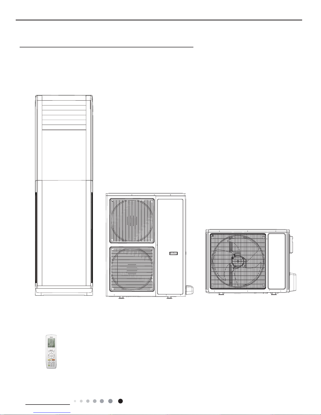
Indoor Unit:
Remote Controller:
Outdoor Unit:
GVA24AL-K3NNC7A/I
GVA48AL-M3NNC7A/I
GVA55AL-M3NNC7A/I
GVA24AL-K3NNC7A/O
GVA48AL-M3NNC7A/O
GVA55AL-M3NNC7A/O
YAP1F4(WiFi)
Service Manual
2
Technical Information
2. Specications
2.1 Specication Sheet
Parameter Unit Value
Model GVA24AL-K3NNC7A
Product Code CG156000200
Power
Supply
Rated Voltage V~ 220-240
Rated Frequency Hz 50
Phases 1
Power Supply Mode Indoor
Cooling Capacity W 7055
Heating Capacity W 7800+2100
Cooling Power Input W 2430
Heating Power Input W 2350
Cooling Power Current A 10.49
Heating Power Current A 10.15
Rated Input W 4800
Rated Current
A 12.09
Air Flow Volume(SH/H/M/L/SL) m3/h
1100/1000/900/800/-
Dehumidifying Volume L/h
2.50
EER
W/W
2.90
COP W/W 3.32
SEER W/W /
HSPF W/W /
Application Area m
2
32-50
Indoor Unit
Model of indoor unit GVA24AL-K3NNC7A/I
Product Code CG156N00200
Fan Type Centrifugal
Diameter Length(DXL) mm Φ350X130.5
Fan Motor Cooling Speed(SH/H/M/L/SL) r/min 450/415/380/345/-
Fan Motor Heating Speed(SH/H/M/L/SL) r/min 450/415/380/345/-
Output of Fan Motor W 60
Fan Motor RLA A 0.72
Fan Motor Capacitor μF 4
Heater Power Input W 2100
Evaporator Form Aluminum Fin-copper Tube
Pipe Diameter mm Φ7
Row-n Gap mm 2 - 1.3
Coil Length (LXDXW) mm 724X25.4X392
Swing Motor Model MP35AA/MP24TA
Output of Swing Motor W 2.5/1.5
Fuse A 5
Sound Pressure Level (SH/H/M/L/SL) dB (A) 46/44/41/38/-
Sound Power Level (SH/H/M/L/SL) dB (A) 56/54/51/48/-
Dimension (WXHXD) mm 507X1770X320
Dimension of Carton Box (LXWXH) mm 1985X620X425
Dimension of Package(LXWXH) mm 1988X623X440
Net Weight kg 40
Gross Weight kg 52
Service Manual
3
Technical Information
The above data is subject to change without notice; please refer to the nameplate of the unit.
Outdoor Unit
Model of Outdoor Unit GVA24AL-K3NNC7A/O
Product Code CG156W00200
Compressor Manufacturer/Trademark ZHUHAI LANDA COMPRESSOR CO., LTD
Compressor Model QXAS-F255N450
Compressor Oil RB68EP or FVC68D or FV50S
Compressor Type Rotary
L.R.A. A 53.00
Compressor RLA A 9.40
Compressor Power Input W 2060
Overload Protector UP14PE5245
Throttling Method Capillary
Operation Temp ºC 16~30
Ambient Temp (Cooling) ºC 18~43
Ambient Temp (Heating) ºC -15~24
Condenser Form Aluminum Fin-copper Tube
Pipe Diameter mm Ф7
Rows-n Gap mm 2.5-1.4
Coil Length (LXDXW) mm 660X38.1X935
Fan Motor Speed rpm 780
Output of Fan Motor W 85
Fan Motor RLA A 0.8
Fan Motor Capacitor μF 4.5
Air Flow Volume of Outdoor Unit m3/h 3200
Fan Type Axial-ow
Fan Diameter mm Ф520
Defrosting Method Automatic Defrosting
Climate Type T1
Isolation I
Moisture Protection IPX4
Permissible Excessive Operating
Pressure for the Discharge Side
MPa 4.3
Permissible Excessive Operating
Pressure for the Suction Side
MPa 2.5
Sound Pressure Level (H/M/L) dB (A) 56/-/-
Sound Power Level (H/M/L) dB (A) 66/-/-
Dimension (WXHXD) mm 965X700X396
Dimension of Carton Box (LXWXH) mm 1026X455X735
Dimension of Package(LXWXH) mm 1029X458X750
Net Weight kg 60
Gross Weight kg 64.5
Refrigerant R410A
Refrigerant Charge kg 1.95
Connection
Pipe
Length m 5
Gas Additional Charge g/m 50
Outer Diameter Liquid Pipe mm Ф6
Outer Diameter Gas Pipe mm Ф16
Max Distance Height m 10
Max Distance Length m 25
Note: The connection pipe applies metric diameter.
Service Manual
4
Technical Information
Parameter Unit Value
Model GVA48AL-M3NNC7A
Product Code CG156000300
Power
Supply
Rated Voltage V~ 380-415
Rated Frequency Hz 50
Phases 3
Power Supply Mode Outdoor
Cooling Capacity W 14100
Heating Capacity W 15500+3500
Cooling Power Input W 5000
Heating Power Input W 4830
Cooling Power Current A 9.9
Heating Power Current A 9.56
Rated Input W 9500
Rated Current
A 14.6
Air Flow Volume(SH/H/M/L/SL) m3/h
1800/1650/1500/1350/-
Dehumidifying Volume L/h
5
EER
W/W
2.82
COP W/W 3.21
SEER W/W /
HSPF W/W /
Application Area m
2
55-85
Indoor Unit
Model of indoor unit GVA48AL-M3NNC7A/I
Product Code CG156N00300
Fan Type Centrifugal
Diameter Length(DXL) mm Φ369X180.5
Fan Motor Cooling Speed(SH/H/M/L/SL) r/min 550/490/440/390/-
Fan Motor Heating Speed(SH/H/M/L/SL) r/min 550/490/440/390/-
Output of Fan Motor W 150
Fan Motor RLA A 1.50
Fan Motor Capacitor μF 6
Heater Power Input W 3500
Evaporator Form Aluminum Fin-copper Tube
Pipe Diameter mm Φ7
Row-n Gap mm 3-1.4
Coil Length (LXDXW) mm 876X25.4X472
Swing Motor Model MP24TA /MP35AB
Output of Swing Motor W 1.5/2.5
Fuse A 5
Sound Pressure Level (SH/H/M/L/SL) dB (A) 52/50/48/45/-
Sound Power Level (SH/H/M/L/SL) dB (A) 62/60/58/55/-
Dimension (WXHXD) mm 587X1882X394
Dimension of Carton Box (LXWXH) mm 2150X735X530
Dimension of Package(LXWXH) mm 2153X738X545
Net Weight kg 61
Gross Weight kg 83.5
Service Manual
5
Technical Information
The above data is subject to change without notice; please refer to the nameplate of the unit.
Outdoor Unit
Model of Outdoor Unit GVA48AL-M3NNC7A/O
Product Code CG156W00300
Compressor Manufacturer/Trademark ZHUHAI LANDA COMPRESSOR CO., LTD
Compressor Model QXAS-H59sN330A
Compressor Oil FW68DA
Compressor Type Rotary
L.R.A. A 72.00
Compressor RLA A 9.00
Compressor Power Input W 4900
Overload Protector UP14PE5245
Throttling Method Capillary
Operation Temp ºC 16~30
Ambient Temp (Cooling) ºC 18~43
Ambient Temp (Heating) ºC -15~24
Condenser Form Aluminum Fin-copper Tube
Pipe Diameter mm Ф7.94
Rows-n Gap mm 2-1.4
Coil Length (LXDXW) mm 866X38.1X1210
Fan Motor Speed rpm 840
Output of Fan Motor W 68
Fan Motor RLA A 0.65
Fan Motor Capacitor μF 3.5
Air Flow Volume of Outdoor Unit m3/h 6000
Fan Type Axial-ow
Fan Diameter mm Ф470
Defrosting Method Automatic Defrosting
Climate Type T1
Isolation I
Moisture Protection IPX4
Permissible Excessive Operating
Pressure for the Discharge Side
MPa 4.3
Permissible Excessive Operating
Pressure for the Suction Side
MPa 2.5
Sound Pressure Level (H/M/L) dB (A) 56/-/-
Sound Power Level (H/M/L) dB (A) 66/-/-
Dimension (WXHXD) mm 1032X1250X412
Dimension of Carton Box (LXWXH) mm 1110X450X1280
Dimension of Package(LXWXH) mm 1113X453X1400
Net Weight kg 107.0
Gross Weight kg 118.0
Refrigerant R410A
Refrigerant Charge kg 4.1
Connection
Pipe
Length m 5
Gas Additional Charge g/m 120
Outer Diameter Liquid Pipe mm Ф12
Outer Diameter Gas Pipe mm Ф19
Max Distance Height m 20
Max Distance Length m 30
Note: The connection pipe applies metric diameter.
Service Manual
6
Technical Information
Parameter Unit Value
Model GVA55AL-M3NNC7A
Product Code CG156000100
Power
Supply
Rated Voltage V~ 380-415
Rated Frequency Hz 50
Phases 3
Power Supply Mode Outdoor
Cooling Capacity W 15200
Heating Capacity W 17000+3500
Cooling Power Input W 5410
Heating Power Input W 5290
Cooling Power Current A 11.72
Heating Power Current A 11.24
Rated Input W 11100
Rated Current A 17.6
Air Flow Volume(SH/H/M/L/SL) m3/h 1800/1650/1500/1350/-
Dehumidifying Volume L/h 5.5
EER W/W 2.81
COP W/W 3.21
SEER W/W /
HSPF W/W /
Application Area m
2
80-100
Indoor Unit
Model of indoor unit GVA55AL-M3NNC7A/I
Product Code CG156N00100
Fan Type Centrifugal
Diameter Length(DXL) mm Φ369X180.5
Fan Motor Cooling Speed(SH/H/M/L/SL) r/min 550/490/440/390/-
Fan Motor Heating Speed(SH/H/M/L/SL) r/min 550/490/440/390/-
Output of Fan Motor W 150
Fan Motor RLA A 1.50
Fan Motor Capacitor μF 6
Heater Power Input W 3500
Evaporator Form Aluminum Fin-copper Tube
Pipe Diameter mm Φ7
Row-n Gap mm 3-1.4
Coil Length (LXDXW) mm 876X25.4X472
Swing Motor Model MP24TA /MP35AB
Output of Swing Motor W 1.5/2.5
Fuse A 5
Sound Pressure Level (SH/H/M/L/SL) dB (A) 52/50/47/44/-
Sound Power Level (SH/H/M/L/SL) dB (A) 62/60/57/54/-
Dimension (WXHXD) mm 587X1882X394
Dimension of Carton Box (LXWXH) mm 2150X735X530
Dimension of Package(LXWXH) mm 2153X738X545
Net Weight kg 61
Gross Weight kg 83.5
Service Manual
7
Technical Information
The above data is subject to change without notice; please refer to the nameplate of the unit.
Outdoor Unit
Model of Outdoor Unit GVA55AL-M3NNC7A/O
Product Code CG156W00100
Compressor Manufacturer/Trademark ZHUHAI LANDA COMPRESSOR CO., LTD
Compressor Model QXAS-H64sN330
Compressor Oil FW68DA
Compressor Type Rotary
L.R.A. A 85.00
Compressor RLA A 10.60
Compressor Power Input W 5450
Overload Protector UP18WA12R-220
Throttling Method Capillary
Operation Temp ºC 16~30
Ambient Temp (Cooling) ºC 18~43
Ambient Temp (Heating) ºC -15~24
Condenser Form Aluminum Fin-copper Tube
Pipe Diameter mm Ф7.94
Rows-n Gap mm 2-1.4
Coil Length (LXDXW) mm 866X38.1X1210
Fan Motor Speed rpm 840
Output of Fan Motor W 68
Fan Motor RLA A 0.65
Fan Motor Capacitor μF 3.5
Air Flow Volume of Outdoor Unit m3/h 6000
Fan Type Axial-ow
Fan Diameter mm Ф470
Defrosting Method Automatic Defrosting
Climate Type T1
Isolation I
Moisture Protection IPX4
Permissible Excessive Operating
Pressure for the Discharge Side
MPa 4.3
Permissible Excessive Operating
Pressure for the Suction Side
MPa 2.5
Sound Pressure Level (H/M/L) dB (A) 60/-/-
Sound Power Level (H/M/L) dB (A) 70/-/-
Dimension (WXHXD) mm 1032X1250X412
Dimension of Carton Box (LXWXH) mm 1110X450X1280
Dimension of Package(LXWXH) mm 1113X453X1400
Net Weight kg 107.0
Gross Weight kg 118.0
Refrigerant R410A
Refrigerant Charge kg 4.2
Connection
Pipe
Length m 5
Gas Additional Charge g/m 120
Outer Diameter Liquid Pipe mm Ф12
Outer Diameter Gas Pipe mm Ф19
Max Distance Height m 20
Max Distance Length m 30
Note: The connection pipe applies metric diameter.
Service Manual
8
Technical Information
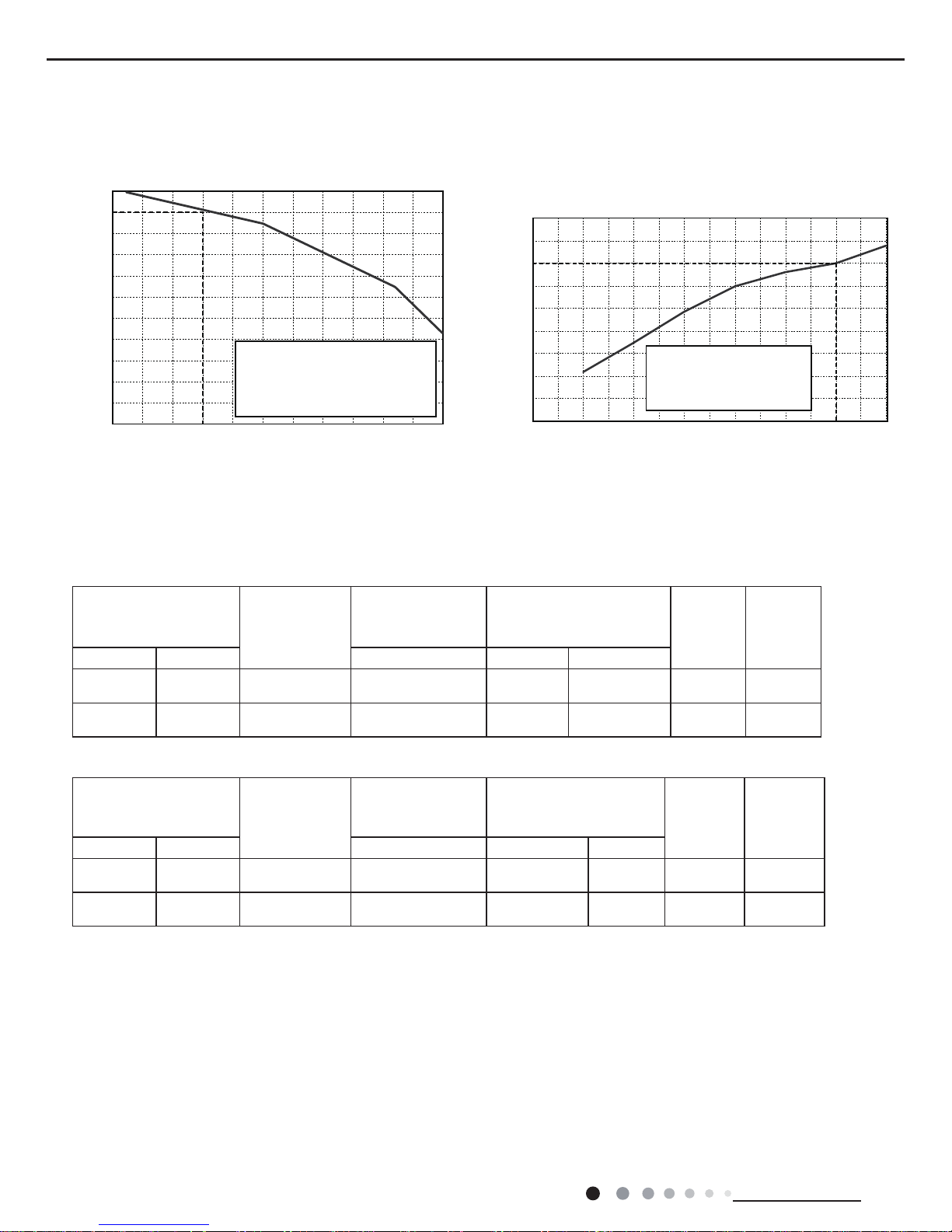
2.2 Operation Characteristic Curve
Cooling Heating
32 33 34 35 36 37 38 39 43
40 41 42
100
105
95
90
85
80
75
70
65
60
55
50
Conditions
Indoor:DB27°C/WB19°C
Indoor air flow:Super High
Pipe length: 5m
Outdoor temp.(°C)
Capacity ratio (%)
30
40
50
60
70
80
90
100
110
120
10
-5-1
05
70-15-20
Outdoor temp.(oC)
Capacity ratio(%)
Conditions
Indoor:DB20°C/WB15°C
Indoor air flow:Super High
Pipe length: 5m
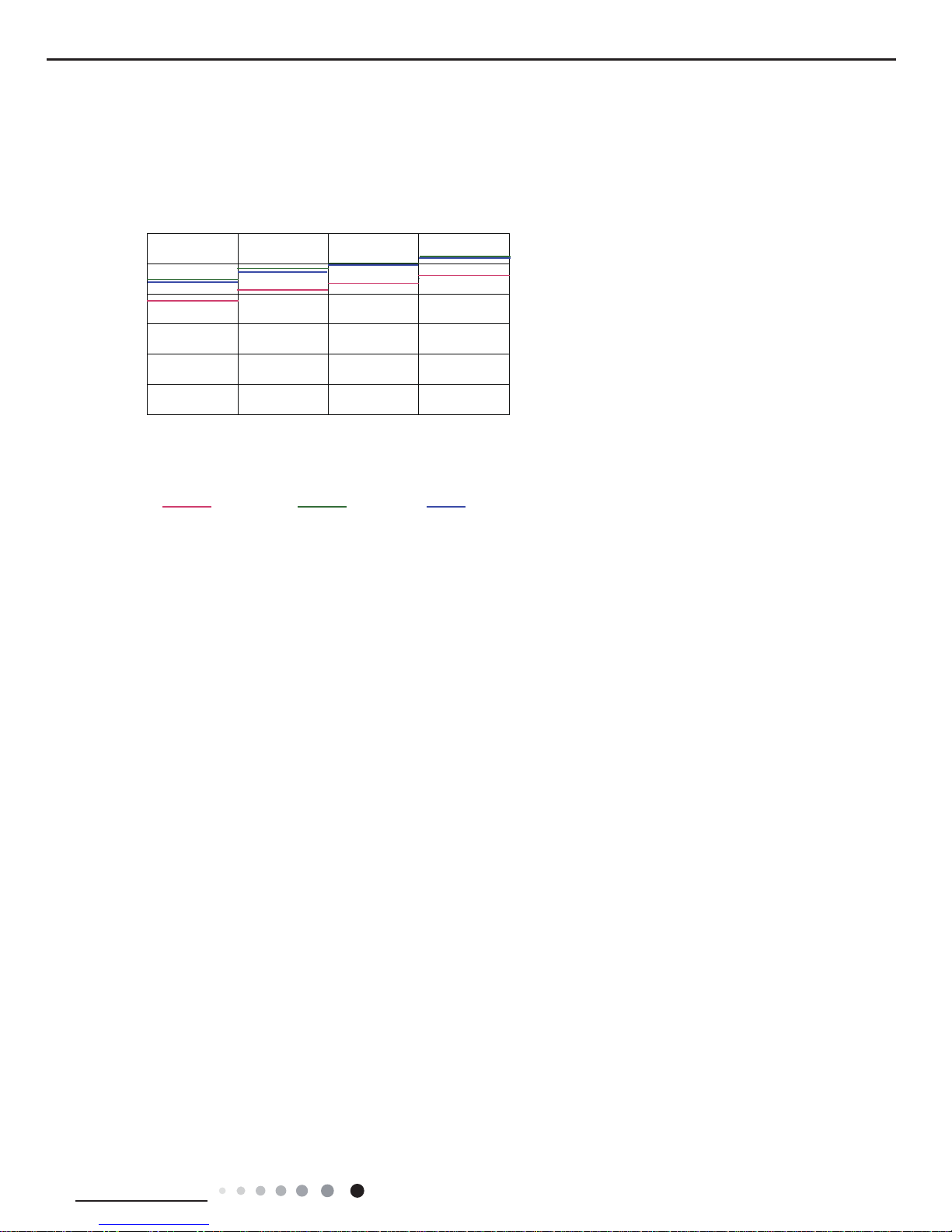
2.3 Cooling Data Sheet in Rated Frequency
Instruction:
T1: Inlet and outlet pipe temperature of evaporator
T2: Inlet and outlet pipe temperature of condenser
P: Pressure at the side of big valve
Connection pipe length: 5 m.
Rated cooling condition(°C)
(DB/WB)
Model
Pressure of gas pipe
connecting indoor and
outdoor unit
Inlet and outlet pipe
temperature of heat exchanger
Fan speed
of indoor
unit
Fan speed
of outdoor
unit
Indoor Outdoor P (MPa) T1 (°C) T2 (°C)
27/19 35/24 24K 0.58 to 1.0
in:8~11
out:11~14
in:75~85
out:37~43
Super High High
27/19 35/24 48/55K 0.8 to 0.9
in:8~11
out:11~14
in:75~85
out:37~43
Super High High
Rated heating condition(°C)
(DB/WB)
Model
Pressure of gas pipe
connecting indoor and
outdoor unit
Inlet and outlet pipe
temperature of heat
exchanger
Fan speed of
indoor unit
Fan speed of
outdoor unit
Indoor Outdoor P (MPa) T1 (°C) T2 (°C)
20/- 7/6 24K 2.5 to 3.0
in:75~85
out:37~43
in:1~3
out:3~5
Super High High
20/- 7/6 48/55K 3.0 to 3.1
in:75~85
out:37~43
in:1~3
out:3~5
Super High High
Cooling:
Heating:
Service Manual
9
Technical Information
2.4 Noise Curve
24K 48K 55K
60
50
40
30
20
10
0
Noice/dB(A)
low
Middle
High Super High
Indoor side noise when blowing
Indoor fan motor rotating speed
Service Manual
10
Technical Information
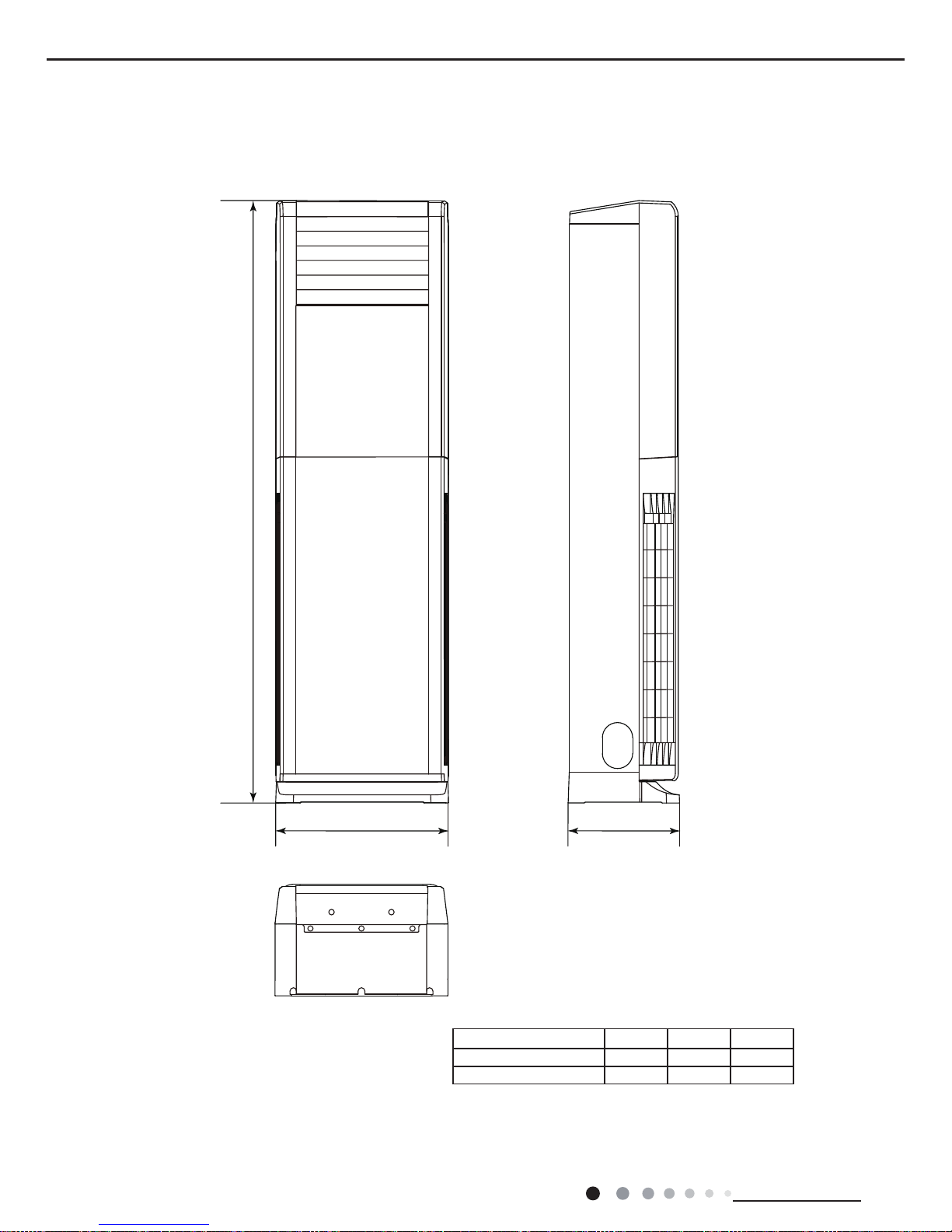
3. Outline Dimension Diagram
3.1 Indoor Unit
Unit:mm
+
:'
Model W H D
24K 507 1770 320
48/55K 587 1882 394
Service Manual
11
Technical Information
Unit:mm
Unit:mm
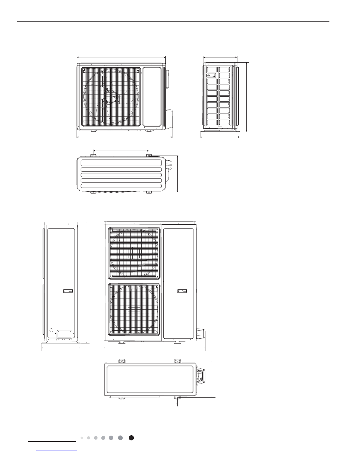
3.2 Outdoor Unit
364
560
700
396
340
965
897
24K
48K/55K
1032
572
378
412
1250
Service Manual
12
Technical Information
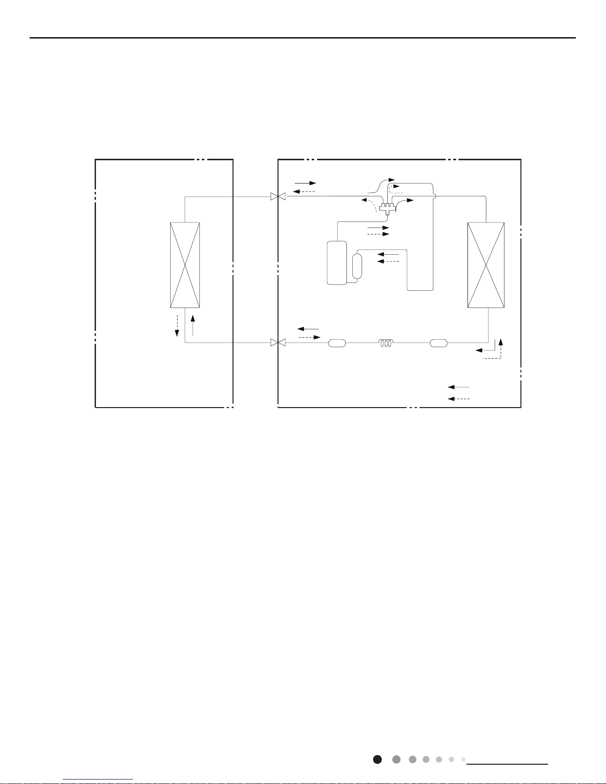
4. Refrigerant System Diagram
Cooling and heating model
Indoor unit
Outdoor unit
Indoor unit
Outdoor unit
COOLING
HEATING
Accumlator
4-Way valve
COOLING
Discharge
Suction
Discharge
Suction
Heat
exchanger
(evaporator)
Heat
exchanger
(evaporator)
Heat
exchanger
(condenser)
Heat
exchanger
(condenser)
Valve
Valve
Valve
Valve
Liquid pipe
side
Gas pipe
side
Liquid pipe
side
Gas pipe
side
Compressor
Accumlator
Compressor
Strainer
Strainer StrainerCapillary
Capillary
Connection pipe specication:
Liquid pipe:1/4" (6mm) 24K
Liquid pipe:1/2" (12mm) 48/55K
Gas pipe:5/8" (16mm) 24K
Gas pipe:3/4" (19mm) 48/55K
Service Manual
13
Technical Information
287'22581,7
1
6:,1*8'
%8
;7
1
6:,1*/5
7(50,1$/
%/2&.
%.
$&/
%1
%8
%.
%1
<(*1
$335,17('&,5&8,7%2$5'
3(
%8
%1
<(*1
32:(5
1
/
76(1625
7(03
5220
57
57
0
0
&20',63/$<
&200$,1
$3',63/$<
;
0
<(*1
&
)$1
3(
)$102725
6(1625
7(03
78%(
6(1625
/
1
83'2:1
67(33,1*
02725
/()75,*+7
67(33,1*
02725
%1
%8
&20
&$3
&211(&725
.0
,+($71
2+($71
.0
.B+($7
.B+($7
)8
2+($7/
,+($7/
5'
(+
)87
67
+($7(5
%8
%8
%1
127(0RWRU
JURXQGRQO\
DSSOLHVWR
WKHLURQ
VKHOOPRWRU
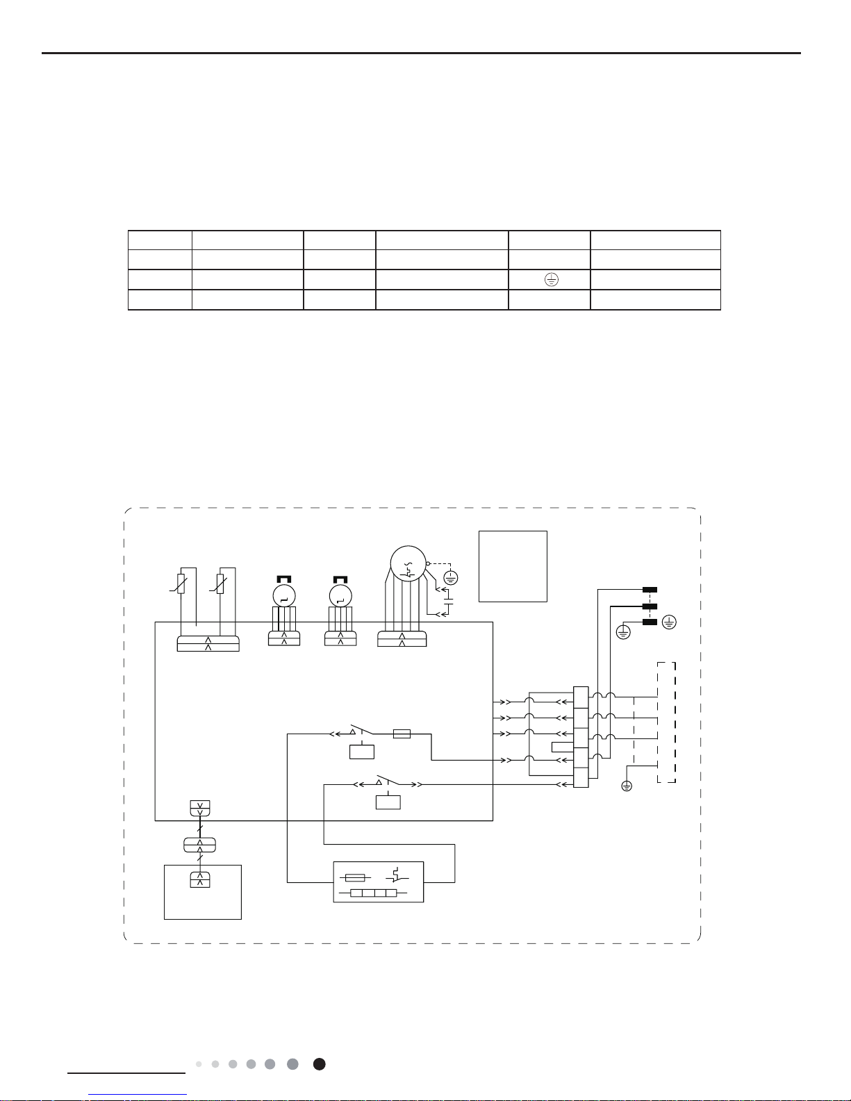
5. Electrical Part
5.1 Wiring Diagram
●
Indoor Unit
● Instruction
Symbol Symbol Color Symbol Symbol Color Symbol Name
YE Yellow BN Brown COMP Compressor
RD Red BU Blue Grounding wire
YEGN Yellow/Green BK Black / /
600007001381
24K
Service Manual
14
Technical Information
:+
5'
%.
%8
%8
%8
%1
2+($7
,+($7/
,+($7/
2+($7
2+($7
,+($7/
6:,1*/5
0
%.
97
35,17('&,5&8,7%2$5'
7(50,1$/%/2&.
/
;7
$&/
/
/
,1'22581,7
97
%.
%1
$3
&200$,1
76(1625
57
57
0
1
&20
%1
%.
;
&211(&725
.0
.0
.0
<(*1
%8
1
2+($7
,+($71
.0
287'22581,7
&20287
&20',63/$<
&1
&1
6:,1*8'
)$1
<(*1
3(
0
)$1
&
:+
:+
3(
02725
&1
$3
83'2:1
67(33,1*
02725
/()75,*+7
67(33,1*
02725
7(03
6(1625
78%(
7(03
6(1625
5220
',63/$<
+($57(5
(+
)87
67
600007001208
48/55K
Service Manual
15
Technical Information
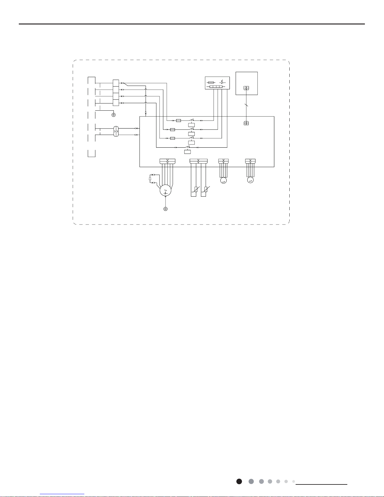
These wiring diagrams are subject to change without notice; please refer to the one supplied with the unit.
● Outdoor Unit
L1
M
XT
BU
CAP.
FAN MOTOR
OUTROOM
3
2
N(1)
KM
COM-INNER
N1
AC-L
COMP
C2
R(M)
S
C
PE
N
OFAN
YEGN
BU
BN
BK
BU
BK
BN
RD
BU
BN RD
TERMINAL
BLOCK
I
TC
TRANSFORMER
RT1
OUTTUBE
TR-OUTTR-IN
CAP.
BK
(BU)
YEGN
PE
PE
COMP
COMP.
PE
YEGN
BK
LPP
C1
(1)
BU
YE
J
BU
BN
BN
BK
HPP
YE
WH
P
HP
HIGH PRESSURE
SWITCH
RT2
RESISTOR
SHIELDING
N
NOTE:Motor
ground only
applies to
the iron
shell motor.
R3
T-PIPE
AP1 PRINTED CIRCUIT BOARD
INDOOR UNIT
(6)
(4)
TEMP.
ROOM
AC CONTACTOR
PE
SENSOR
TEMP.
TUBE
SENSOR
L1/6
A2/1
A1/0
T1/4
4-WAY VALV E
4WAY
N1
VT
4YV
VT
JUMP
CAP
3
.0
$
$
5'
:+
6(1625
7(03
78%(
6(1625
5220
28778%(
57
57
287
2875220
287
7(03
%1
%8
%.
97
%1
%.
97
3527(&725
3+$6(5(9(56(
;7
/
/
/
&20,11(5
1
$&/
&203
$335,17('&,5&8,7%2$5'
1
7(50,1$/
%/2&.
7&
ė
Ė
75$16)250(5
7528775,1
&203
3(
<(*1
6(1625
7(03
73,3(
57
',6&+$5*(
6:,7&+
35(6685(
/2:
/36
/33
:+
%8
%1
%.
97
%8
/
/
/
1
32:(5
7:
79
78
97
%.
%1
$&&217$&725
&
6
5
7
$
(
,1'22581,7
3(
<(*1
&203
3
6:,7&+
35(6685(
+,*+
+36
+33
<(
%8
$3
/ /
3(
<(*1
%1
%.
97
%8
%.
%8
%1
%8
&$3
-803
%8
0
:+
)$102725
&
%1
%.
<(*1
3(
5'
5'
3(
<(*1
%.
%1
1
&
)$102725
:+
0
;7
2)$1
(+
&203%$1'
+($7(5
+($77,(
&$3
&$3
%1
%1
7(50,1$/
%/2&.
2*
%8
2*
%8
%1
127(0RWRU
JURXQGRQO\
DSSOLHVWR
WKHLURQ
VKHOOPRWRU
:$<
:$<
97
<9
97
9$/9(
1
;;
600007001387
600007001207
48/55K
24K
Service Manual
16
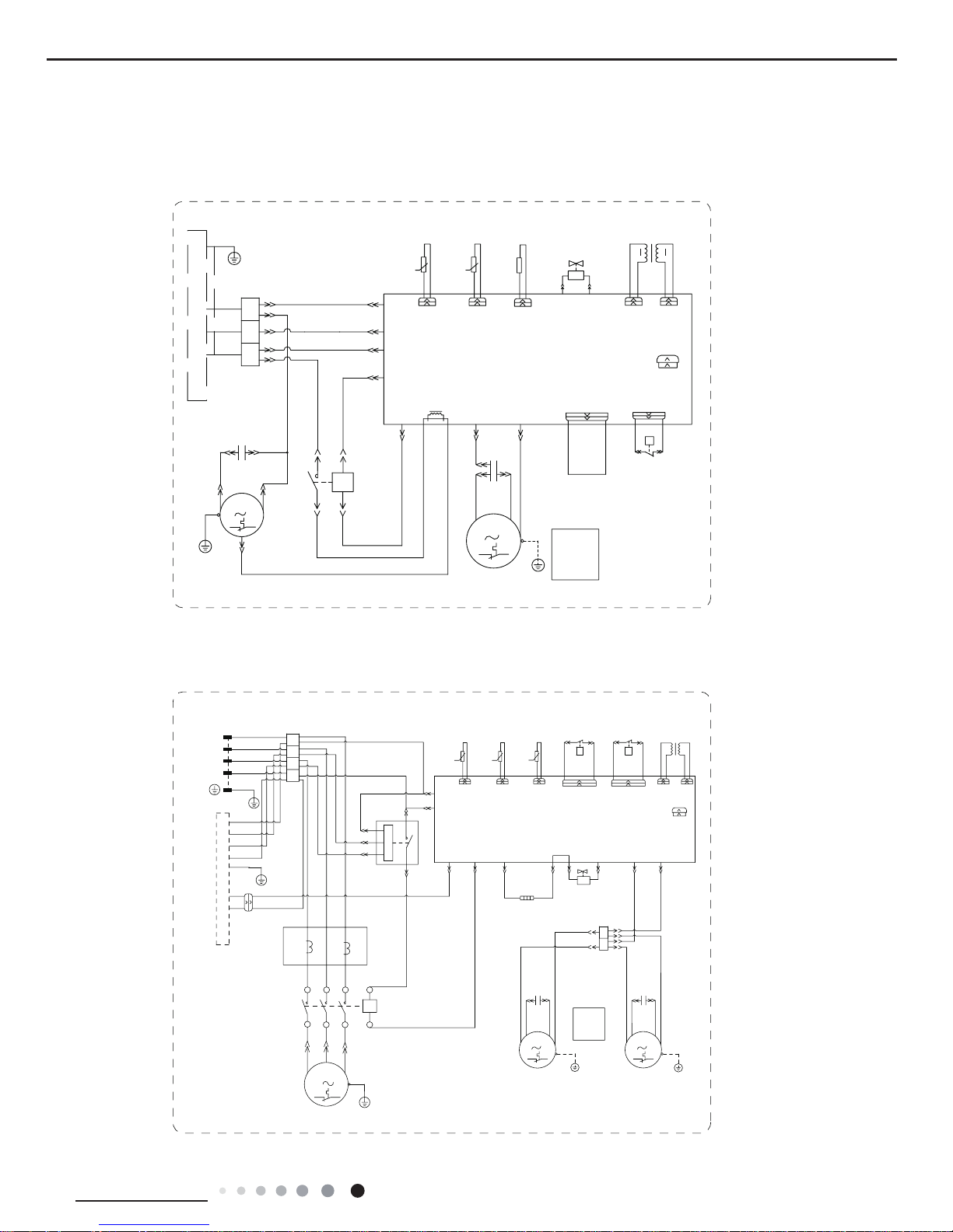
Technical Information
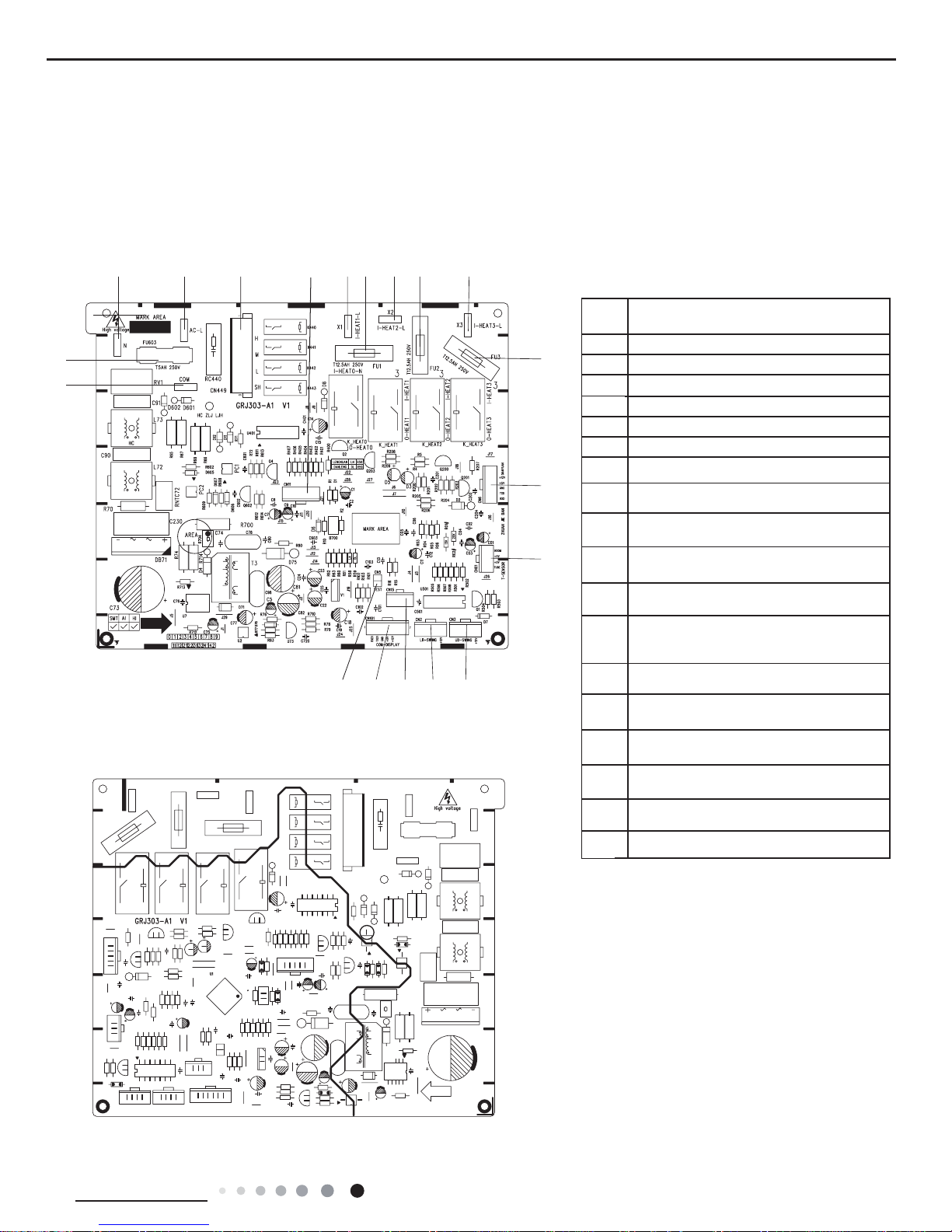
5.2 PCB Printed Diagram
Indoor unit
Terminal with outdoor unit
communication wire
1
22Netural wire
3Iive wire
4
43
Fuse
55Heater Iive wire
66Needle stand for indoor fan
77Up&down swing interface
8
8
Left&right swing interface
9
9
Temperature sensor
10
10
Display board
● ● Top view
Bottom view
1
24K
Service Manual
17
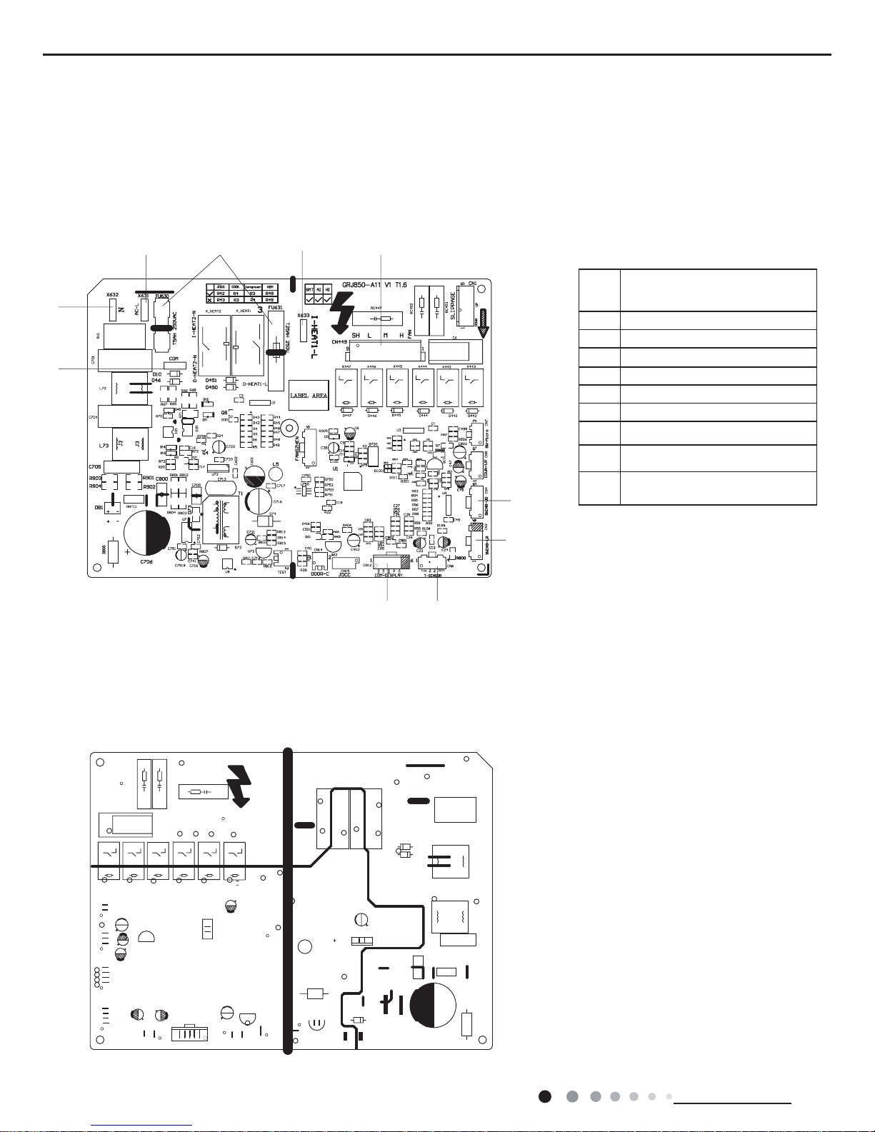
Technical Information
Compressor wiring terminal
1
22Fuse
3Interface of netural wire
4
43
Interface of live wire
55Needle stand for indoor fan
66Needle stand of simulation port
77Live wire terminal of E-heater1
8
8
Fuse of E-heater1
9
9
Live wire terminal of E-heater2
10
10 11
12
13
14
1516
17
1819
Fuse of E-heater2
11
Live wire terminal of E-heater3
12
Fuse of E-heater3
13
Needle stand connected with
drive board of DC motor
14
Interface of temperature sensor
15
up&down swing interface
16
Left&right swing interface
17
RS485 Communication interface
18
connection with display board
19
Needle stand of fast-detection port
● ● Top view
Bottom view
1
48/55K
Service Manual
18
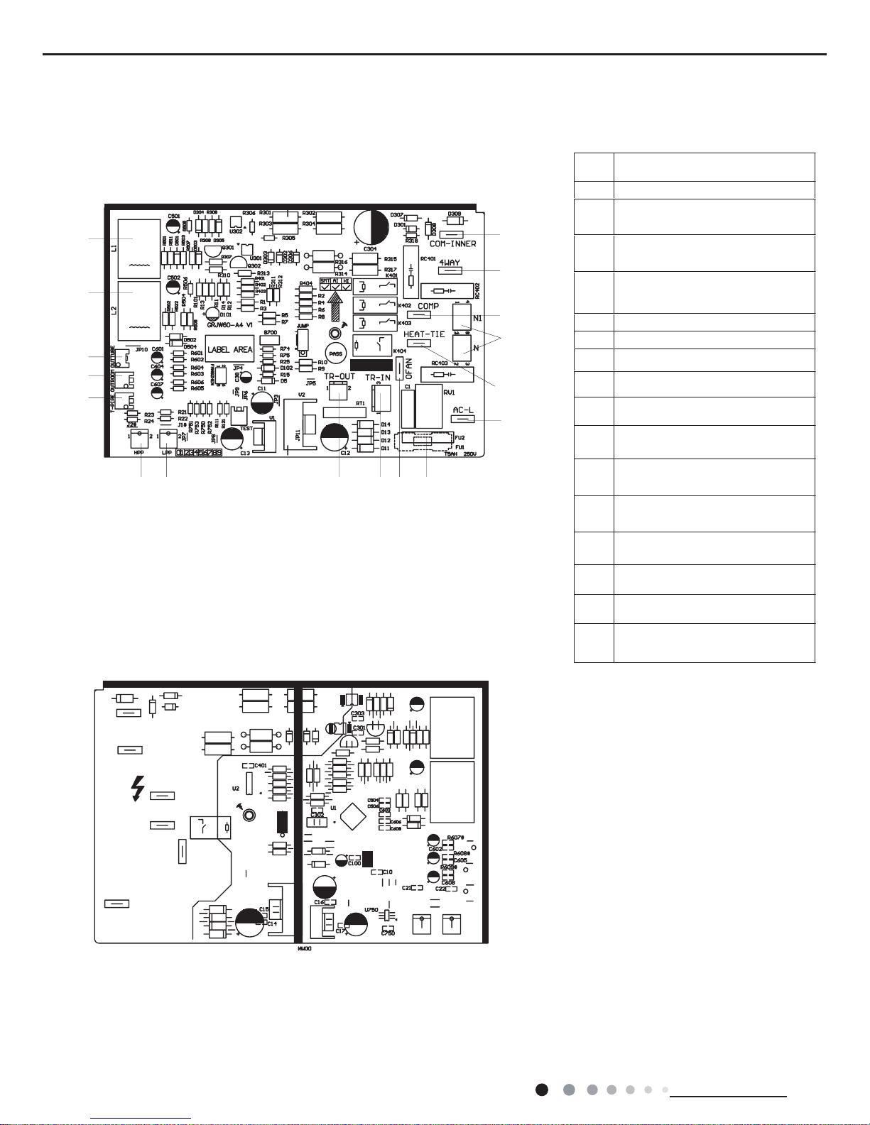
Technical Information
Outdoor unit
Current mutual-inductor L1
22Current mutual-inductor L2
3
3
Terminal for outdoor tube
temperature sensor
4
4
Terminal for outdoor ambient
temperature sensor
5
5
Terminal for outdoor discharge
temperature sensor
66Interface of high pressure switch
77Interface of low pressure switch
8
8
Output terminal of transformer
9
9
Input terminal of transformer
10
10
11
11
12
12
13
13
14
14
15
15
16
16
17
17
Terminal of outdoor fan
Live wire
Fuse
Neutral wire
Interface of electric heating belt
of compressor
Terminal for compressor
Interface of 4-way valve
Terminal with indoor unit
communication wire
● ● Top view
Bottom view
1
1
Service Manual
19
Technical Information
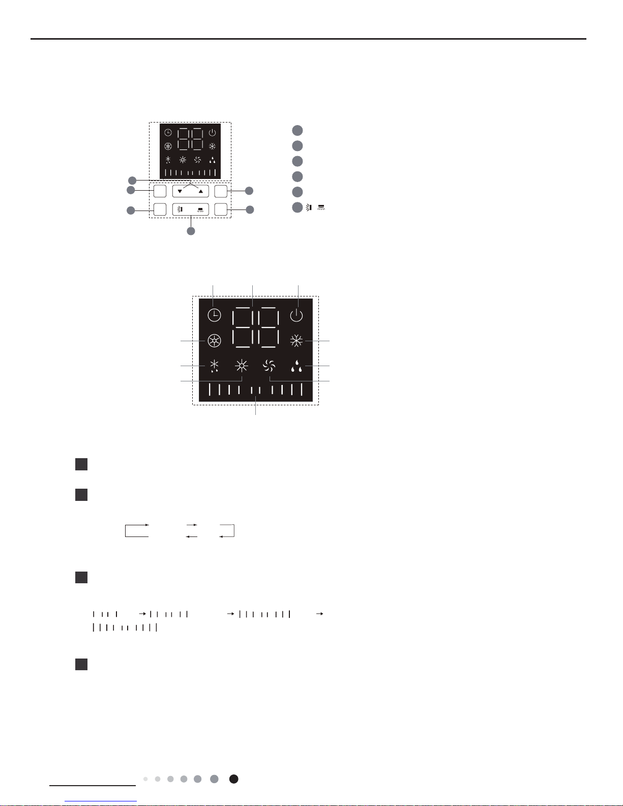
6. Function and Control
Button’s Name and Function
Introduction for icons on display screen of air conditioner
Timer
display
Ambient temperature
or set temperature
display or others
Operation
Cooling display
Dry display
Fan display
E-Heater display
Defrosting display
Heating display
Fan speed display
display
1
6
2
3
4
5
4
FUNCTION button
2
MODE button
MODE
3
FAN button
FAN
FUNC.
1
ON/OFF button
ON/OFF
5
▼/▲ button
6
button
/
ON/OFF button
MODE button
1
2
FAN button
3
●
This series unit adopts touch buttons. You only need to touch the buttons slightly.
Press this button to turn on or turn off the unit.(Note: Under X-FAN mode, press this button to turn on the unit directly.)
●
Every time press this button, the mode will switchover in cycle among.
(Note: Cooling only unit won’t accept heating operation signal. For cooling only unit, pressing MODE button under FAN mode will
skip heating mode and enter cooling mode.)
COOLING
DRY
HEATING
FAN
●
Press this button and then fan speed can be selected and displayed in the
sequence as below:
(Note:Only low fan speed is available for dry mode. Fan speed can't be adjusted
under dry mode. Turbo cannot be set in FAN mode.)
(low)
(medium) (high)
(turbo)
Note:
FUNCTION button
4
●
●
Under on status, press Function button to switch between timer and auxiliary heating function setting (auxiliary heating
can be set only in heating mode). When timer or auxiliary heating icon is blinking, it means this function can be set. Press
"▲" or "▼"
button to set function. If there’s no operation change within 5s after setting is finished, the function setting will be
confirmed. Or press Function button again to exit or confirm the function.When the function is selected through Function
button, if the unit is not turned off and no remote control signal is received within 2min, pressing Function button again to
circulate from the previous set function.After 2min or the unit is turned off or remote control signal is received, pressing
Function button again to circulate from timer icon. (Note: Only when the unit is under heating mode and with auxiliary heating
function, auxiliary heating function can be turned on or off through Function button.)
Under off status, if the unit is in X-FAN status, press Function button to turn off the unit directly; if the unit is not in X-FAN status,
press Function button to set timer ON.
6.1 Function Buttons of Air Conditioner
Service Manual
20
Technical Information
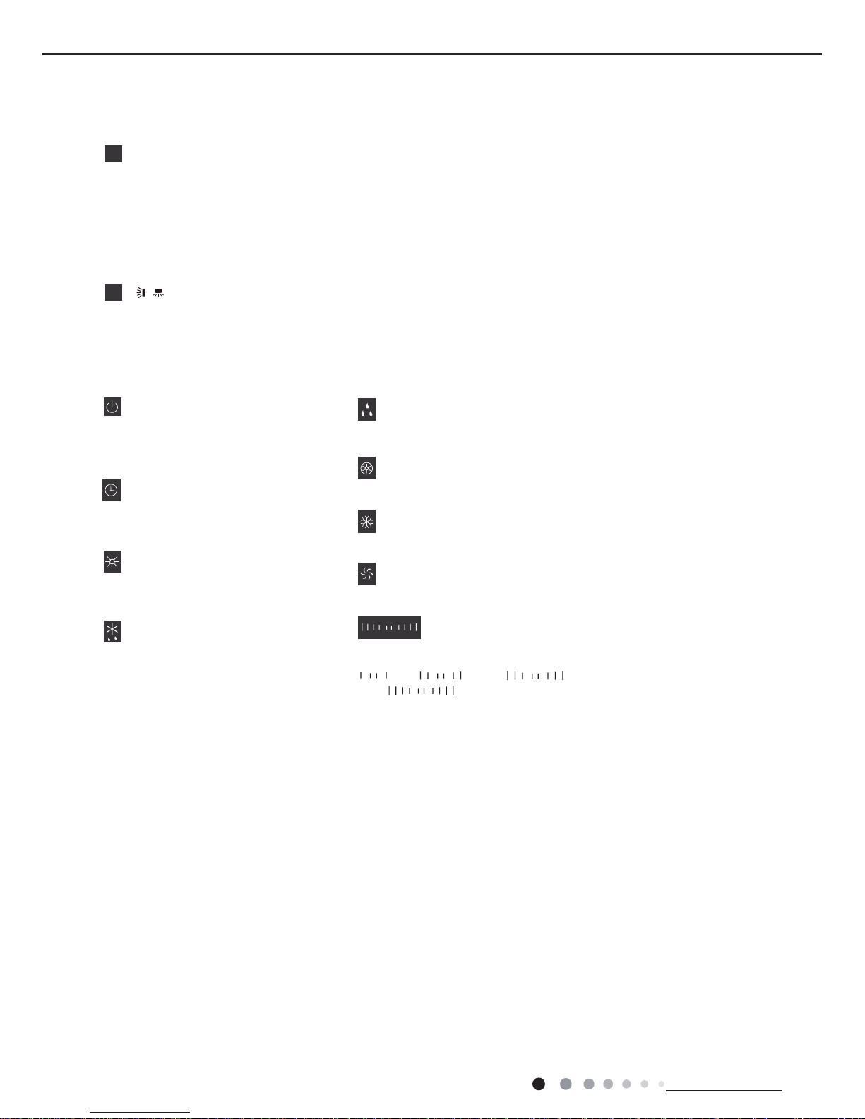
Button’s introduction
Operation display
Timer display
● It indicates the air conditioner is
put through the power. Under on
Heating display
ƽ
When this indicator is on, it
indicates the timer function
is turned on.
status, this indicator is on; under
off status, this indicator is off.
●When this indicator is on, it
indicates the heating mode is
turned on.
●When this indicator is on, it
indicates the defrosting function
is turned on.
ƽ
●
●
When this indicator is on, it indicates
the dry mode is turned on.
When this indicator is on, it indicates
the cooling mode is turned on.
When this indicator is on, it indicates
the E-heater function is turned on.
●When this indicator is on, it indicates
the fan mode is turned on.
● Displays the fan speed. The fan speed
is displayed as below:
Dry display
E-Heater display
Cooling display
Fan display
Icon function introduction
Fan speed display
Defrosting display
(low) → (medium) →
(high) → (turbo)
button
6
●
Left and right swing: this button controls the left and right swing motor, single pressit to switchover between ON and OFF.
●
Up and down swing: this button controls the up and down swing motor, single pressit to switchover between ON and OFF.
▼/▲ button
5
●
After each pressing of "▲" or "▼" button, set temperature will increase or decrease
auto mode. Timer setting can be set in 1h increment among 0~24h. When it is adjusted to
auxiliary heating function setting through Function button,press this button to turn on or turn off auxiliary heating. (Note: auxiliary
heating is valid only for the model with this function.)
1ć
. Temperature adjustment range is
ć
~30
ć
. This button is invalid under
●
Hold "▲" and "▼" buttons for 3s and the air conditioner will display "LC", which indicates buttons are locked. Any button
under on status or ON/OFF button and function buttons under off status are all invalid. Hold these two button for 3s
again to release the lock.
/
16
Service Manual
21
Technical Information
6.2 Remote Control Operations
This is a general use remote controller, it could be used for the air conditioners with multifunction; For some function, which the
model doesn't have, if press the corresponding button on the remote controller that the unit will keep the original running status.
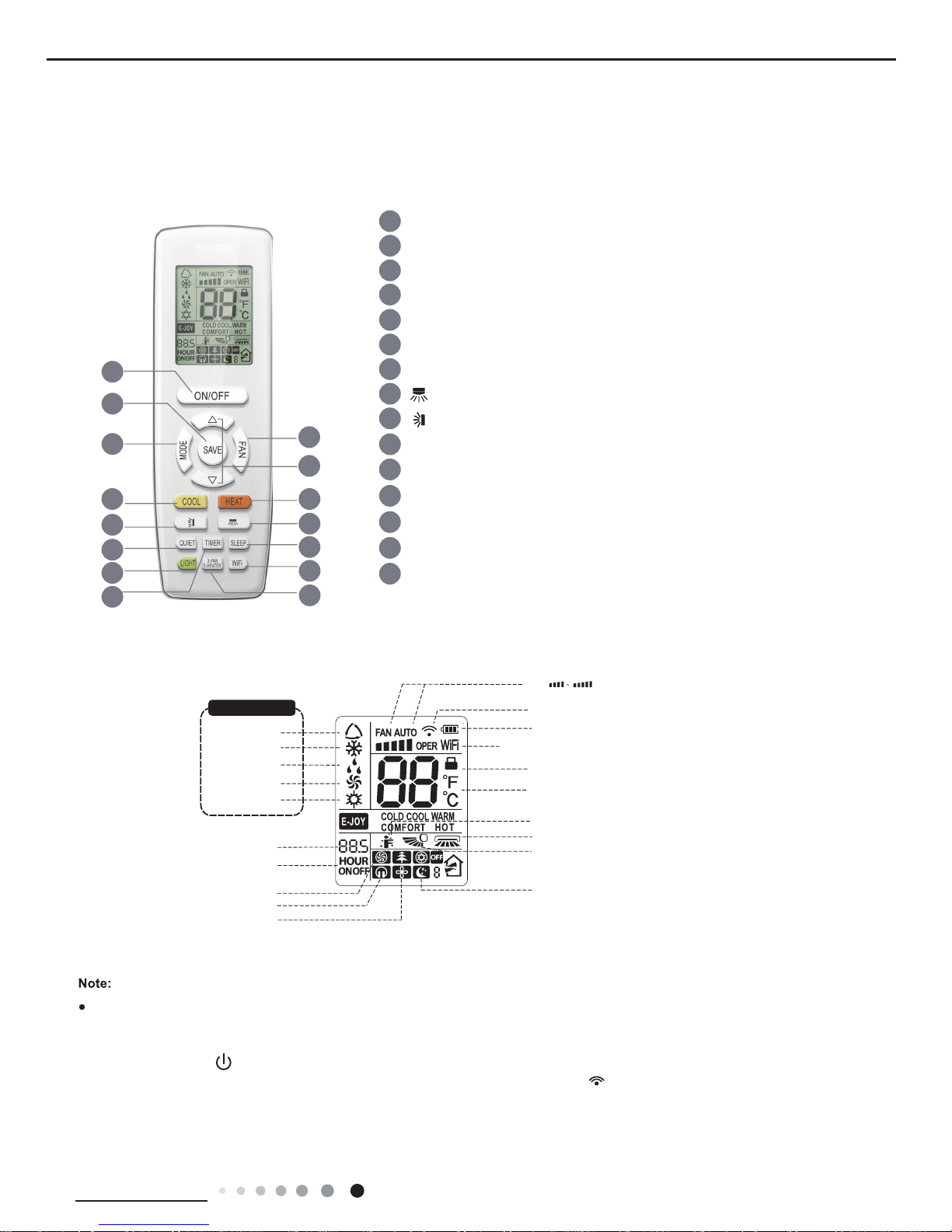
Buttons on remote controller
Introduction for icons on display screen
6
3
7
9
10
14
15
13
12
8
11
5
4
2
1
X-FAN function
Turbo fan speed
Quiet mode
Set fan speed
(No fan speed. It’s displayed
only after turning it on.)
{
Send signal
Switch temperature displaying type on
the unit’s display
Set time
TIMER ON/TIMER OFF
Child lock
Up & down swing
Left & right swing
battery power
Heat mode
Fan mode
Dry mode
Cool mode
Auto mode
Operation mode
I feel function
Sleep mode
WiFi
This is a general remote controller.Some
models have this function while some
do not. Please refer to the actual models.
{
1 ON/OFF button
2 SAVE button
3 FAN button
4 MODE button
6
button
7
button
9
COOL button
14
LIGHT button
15
TIMER button
12
SLEEP button
13
QUIET button
10
HEAT button
8
X-FAN/E-HEATER button
11
WiFi button
5 ▲/ button
▲
Introduction for buttons on remote controller
●
After putting through the power, the air conditioner will give out a sound.
Operation indictor " " is ON.
After that, you can operate the air conditioner by using remote controller.
●
Under on status, pressing the button on the remote controller, the signal icon " "
on the display of remote controller will
blink once and the air conditioner will give out a “di” sound, which means the signal has been sent to the air conditione
r.
Service Manual
22
Technical Information
ON/OFF button
1
SAVE button
2
Press this button can turn on or turn of
f the air conditioner. After turning on the air conditioner, indoor unit will give out a sound.
FAN button
3
Pressing this button can set fan speed circularly as: auto (AUTO), low( ),
medium
( ), high( ), turbo( ).
Auto
● It’s Low fan speed under Dry mode.
● Turbo cannot be set in FAN mode.
● Under
AUTO speed, air conditioner will select proper fan speed automatically according to ex-factory setting.
Note:
Under cooling mode, press this button to start up or turn of
f energy-saving function.When energy-saving function is started up,
"SE" will be shown on remote controlle
r, and air conditioner will adjust the set temperature automatically according to
ex-factory setting to reach to the best energy-saving ef
fect. Press this button again to exit energy-saving function.
▲
▲/ button
5
● Press "▲" or " " button once increase or decrease set temperature 1ć(°F).
Holding "▲" or " " button, 2s later, set temperature
on remote controller will change quickly . On releasing button after setting is finished, temperature indicator on indoor unit will change
accordingly. (Temperature can’t be adjusted under
▲
▲
▲
● When setting TIMER ON, TIMER OFF, press "▲" or " " button to adjust time. (Refer to TIMER button for details)
auto mode)
● When selecting auto mode, air conditioner will operate automatically according to the sensed temperature. Set temperature
can’t be adjusted and will not be
displayed as well. Press "FAN" button can adjust fan speed. Press " " / " " button can adjust
fan blowing angle.
● After selecting cool mode, air conditioner will operate under cool mode. Cool
indicator " " on indoor unit is ON. Press "▲" or " "
FAN" button to adjust fan speed. Press " " / " " button to adjust
fan blowing angle.
● When selecting dry mode, the air conditioner operates at low speed under dry
mode. Dry indicator " " on indoor unit is ON.
Under dry mode, fan speed can’t
be adjusted. Press " " / " " button to adjust fan blowing angle.
● When selecting fan mode, the air conditioner will only blow fan, no cooling and
no heating. Fan indicator " " on indoor unit is ON.
Press "FAN" button to adjust fan speed. Press" " / " " button to adjust fan blowing angle.
● When selecting heating mode, the air conditioner operates under heat mode.
Heat indicator " " on indoor unit is ON. Press "▲" or " "
button to adjust set temperature. Press "FAN" button to adjust fan speed. Press " " / " " button to adjust fan blowing angle. (Cooling only
unit won’t receive heating mode signal. If setting heat mode with remote controller, press ON/OFF button can’t start up the unit).
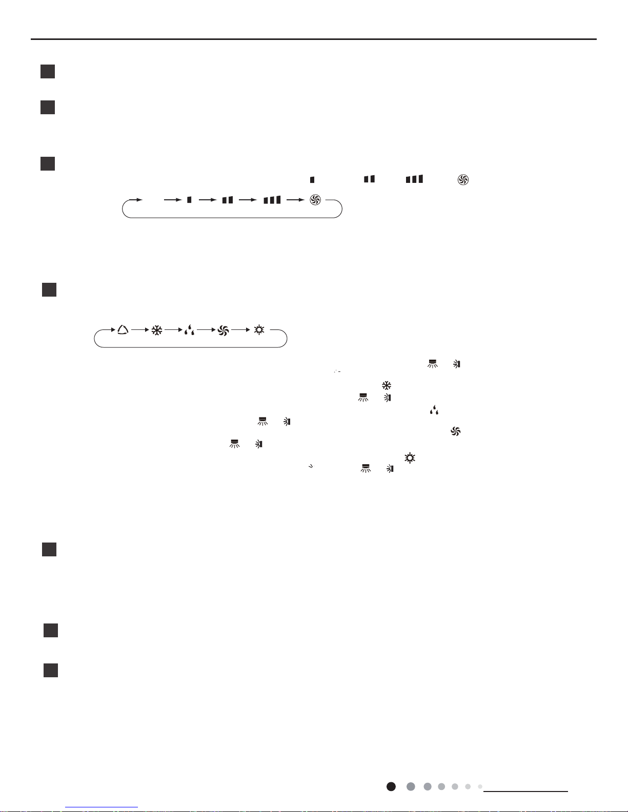
MODE button
▲
▲
4
Press this button to select your required operation mode.
AUTO COOL FANDRYHEAT
Note:
● For preventing cold air, after starting up heating mode, indoor unit will delay 1~5 minutes to blow air (actual delay time is depend on indoor
● Set temperature range from remote controller: 16~30ć(61-86°F);
Fan speed: auto, low speed, medium speed, high speed, turbo speed.
button to adjust set temperature. Press "
ambient temperature).
Cool button
6
● Press this button, unit will operate in cool mode.
● Press this button, unit will operate in heat mode.
Heat button
7
Service Manual
23
Technical Information
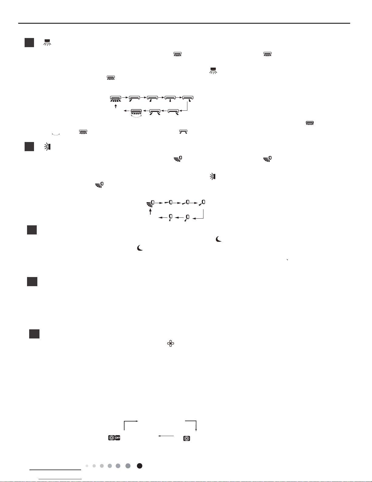
● Under simple swing mode, pres this button can turn on (" " icon is displayed) or
turn off (" " icon is not displayed)
● When the unit is turned off by remote controller, press "▲" button and " "
● This remote controller is the general type remote controller. When remote controller receives the signal of " " , sw
ing
status is same as " " ; when remote controller receives " " , swing status is same as left&right swing OFF.
button can switch between single swing mode
" " on the remote controller will flash twice.
9
Under fixed-angle swing mode, press this button and then left&right swing status will
circulate as shown in the right figure:
● Under simple swing mode, pres this button can turn on (" " icon is displayed)
lor turn off (" " icon is not displayed) the
● When the unit is turned off by remote controller, press "▲" button and " "
button can switch between single swing mode and
" " on the remote controller will flash twice.
Under fixed-angle swing mode, press this button and
the up&down swing status will circulate as shown in the right figure:
button
8
button
no display
no display
10
SLEEP button
Under COOL, or HEAT mode, press this button to start up sleep function.
" " icon is displayed on remote controller
. Press this
button again to cancel sleep function and " " icon will disappear.After powered on, Sleep Off is defaulted. After the unit is
turned off, the Sleep function is canceled. In this mode, the time of time can be adjusted. Under Fan
DRY and Auto modes,
this function is not available.
WiFi button
11
● This function is only available for some models.
Press " WiFi " button to turn on or turn off WiFi function. When WiFi function is turned on, the " WiFi " icon will be displayed on
remote controller; Under status of remote controller off, press "MODE" and " WiFi " buttons simultaneously for 1s,WiFi module
will restore to factory default setting.
12
Pressing this button in COOL or DRY mode, the icon " " is displayed and the
Only under cooling mode and dry mode, press this button can turn on (characters
(characters of “X-FAN” are not displayed)
of “X-FAN” are displayed) or turn off
X-FAN function.
indoor fan will continue operation for a few
minutes in order to dry the indoor unit even though you have turned off the unit. After energization, X-FAN OFF is
defaulted.X-FAN is not available in AUTO, FAN or HEAT mode.
unit will be blowed
This function indicates that moisture on evaporator of indoor
after the unit is stopped to avoid mould.
● Having set XFAN function on: After turning off the unit by pressing ON/OFF
about a few minutes. at low speed.
button indoor fan will continue running for
In this period, press X-FAN button to stop indoor fan directly.
●
●
Under heating mode, press this button and the E-HEATER status will changed circularly as below:
●
Having set XFAN function off: After turning off the unit by pressing ON/OFF
button, the complete unit will be off directly.
X-FAN/E-HEATER button
Auto E-HEATER (no display)
E-HEATER OFF
( is displayed)
E-HEATER ON
( is displayed)
the left&right swing function.
and fixed-angle swing mode.
up&down swing function.
fixed-angle swing mode.
Service Manual
24
Technical Information
LIGHT button
14
Press this button to turn off display light on indoor unit. Press this button again to turn on display light.
●
This function is not available for this unit.
Press this button can turn on or turn off QUIET function.
13
QUIET button
Note:
● Time setting range: 0.5-24 hours.
● Time interval between two operations can’t exceed 5s. Otherwise, remote controller will exit the setting status automatically.
hour. When holding " " or " " button, 2s later, the time will change quickly until to
Cancel TIMER OFF: Press "TIMER" button again under TIMER OFF status.
● At OFF status, press this button once can set TIMER ON. Please refer to TIMER off for detailed operation.
Cancel TIMER ON: Press "TIMER" button again under TIMER ON status.
TIMER button
15
●
At ON status, press this button once can set TIMER OFF. The character of HOUR
TIMER
ON. After each pressing of " " or " " button, time will increase or
decrease half an
▲
▲
▲
▲
▲
▲
Function introduction for combination buttons
Child lock function
Press "▲" and " " simultaneously to turn on or turn off child lock function. When
on remote controller. If you operate
the remote controller, the " " icon will blink three times without sending signal to the unit.
▲
child lock function is on, " " icon is displayed
Temperature display switchover function
Under OFF status, press " " and "MODE" buttons simultaneously to switch temperature display between ć and .
▲
1.
After putting through the power, press "ON/OFF" button on remote controller to turn on the air conditioner.
2.
Press "MODE" button to select your required mode: AUTO, COOL, DRY, FAN, HEAT.
3.
Press "▲" or " " button to set your required temperature. (Temperature can’t be adjusted under auto mode).
4.
Press "FAN" button to set your required fan speed: auto, low speed, medium speed, high speed, turbo speed.
Operation guide
▲
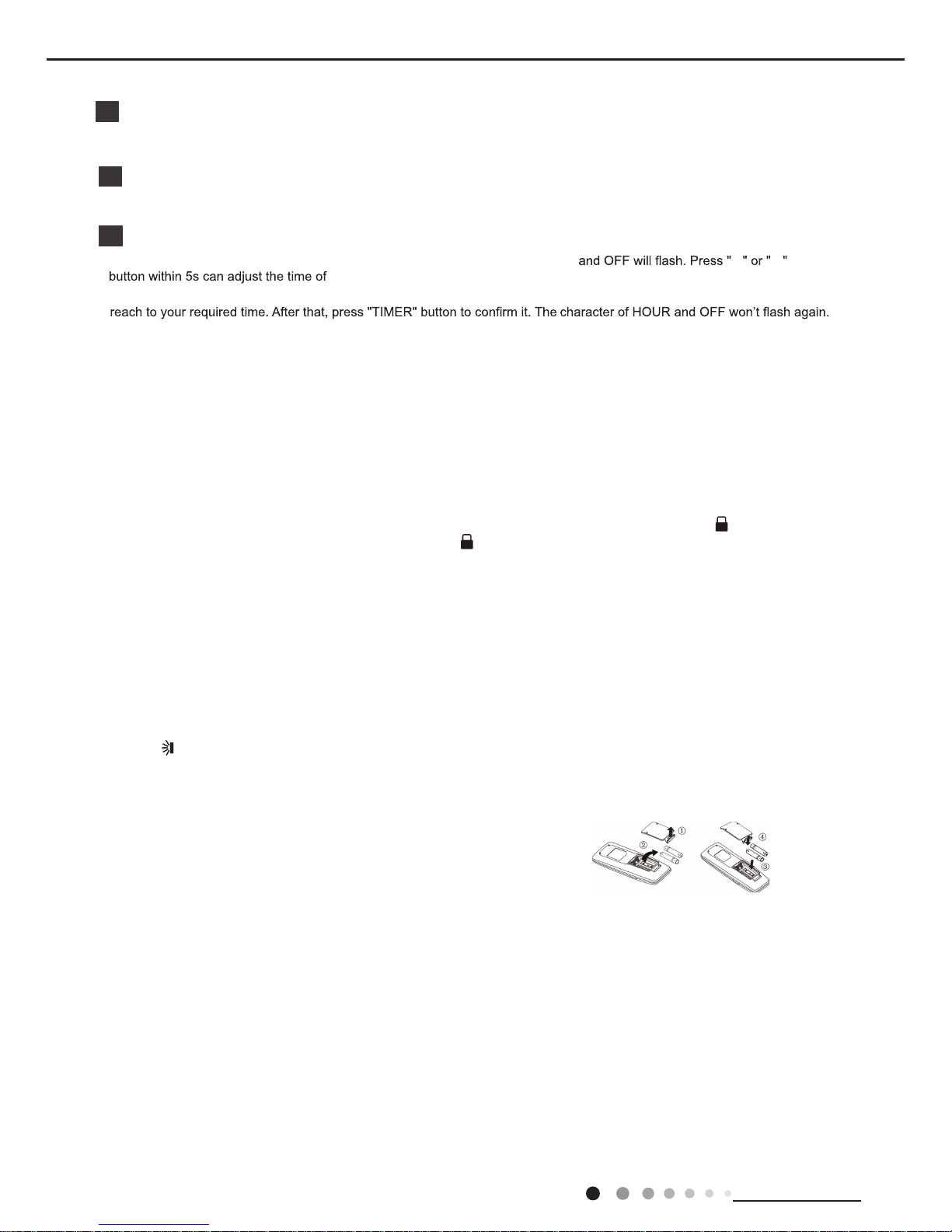
Replacement of batteries in remote controller
● During operation, point the remote control signal sender at the receiving
window on indoor unit.
● The distance between signal sender and receiving window should be no
more than 8m, and there should be no obstacles between them.
● Signal may be interfered easily in the room where there is fluorescent lamp
or wireless telephone; remote controller should be close to indoor unit during
operation.
● Replace new batteries of the same model when replacement is required.
● When you don’t use remote controller for a long time, please take out the
batteries.
● If the display on remote controller is fuzzy or there’s no display, please
replace batteries.
NOTICE
5.
Press " " button to select fan blowing angle.
1. Lift the cover along the direction of arrow (as shown in Fig 1 ①).
2. Take out the original batteries (as shown in Fig 1 ②).
3. Place two 7# (AAA 1.5V) dry batteries, and make sure the position of “+”
polar and “-” polar is correct (as shown in Fig 2
③).
4. Reinstall the cover (as shown in Fig 2 ④).
Fig.1 Fig.2
Service Manual
25
Installation and Maintenance
6.3 Introduction of Each Mode Function
1.Summary
Temperature parameter
◆Indoor set temperature (Tpreset)
◆Indoor ambient temperature (Tamb.)
◆Inner tube temperature of indoor evaporator (Ttube)
2. Introduction of basic mode function
Once the compressor is energized, there should be a minimum interval of 3 mins between two start-ups.
If the unit is with memory function and is off before power failure, the compressor can be restarted without an interval of 3 mins; if the
unit is on before power failure, the compressor will be restarted with an interval of 3 mins.
Once compressor is started, it won’t stop within 6 mins according to the change of room temp.
(1) Auto mode
①
Operation condition and process
Under auto mode, the system will automatically select operation mode (cooling, dry, heating and fan) according to indoor ambient
temperature.
◆
When Tamb.>26℃, the system operates under cooling mode; Ex-factory set temperature is 26℃.
◆
When 20℃≤Tamb.≤26℃, the system operates under drying mode; Ex-factory set temperature is 24℃.
◆
Heat pump unit: when Tamb.<20℃, the system operates under heating mode; Ex-factory set temperature is 20℃.
◆
Cooling only unit: when Tamb.<20℃, the system operates under fan mode; Ex-factory set temperature is 20℃.
②
Protection function is same as that under cooling, drying and heating mode. (See function protection of this section)
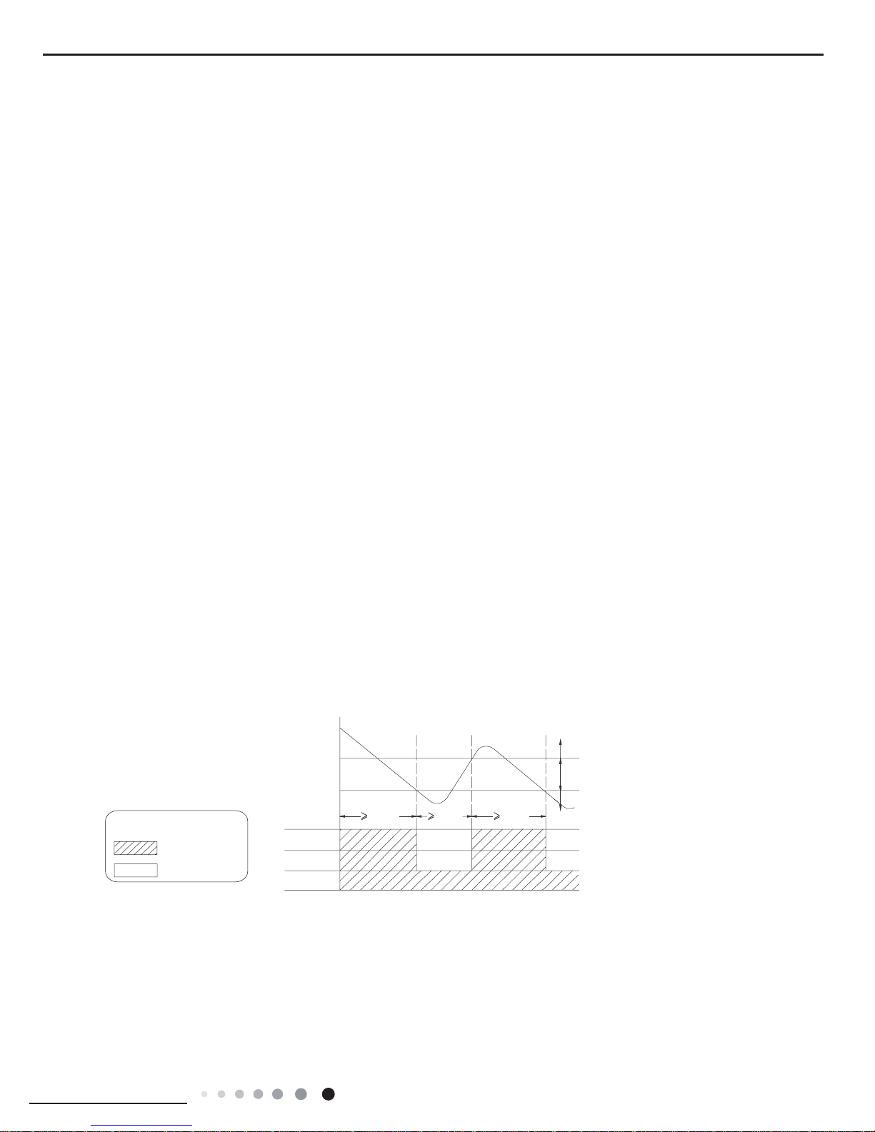
(2) Cooling mode
①
Operation condition and process
◆
When Tamb.≥Tset+1℃, the system operates under cooling mode. In this case, the compressor and the ODU fan motor operate,
and the IDU fan motor operates at set speed.
◆
When Tset-1℃<Tamb.<Tset+1℃, the system will maintain its previous operation status.
◆
When Tamb.≤Tset-1℃, the compressor and the ODU fan motor stop, while the IDU fan motor operates at set speed.
In cooling mode, the 4-way valve is de-energized (4-way valve is not available for cooling only unit). Temperature setting range is
16~30℃.
Indicates operation
Indicates stop
Tpreset +1 ˚C
Tpreset –1 ˚C
Compressor
Outdoor fan motor
Indoor fan motor
Graphic instruction:
(Same as below)
Tamb.
Stop cooling
Start cooling
Original operating status
6 min. 3 min. 6 min.
Set fan speed
②
Protection function (See function protection of this section)
(3) Drying mode
①
Operation condition and process
◆
When Tamb.>Tset+2℃, the system starts drying and cooling. In this case, the compressor and the ODU fan motor operate, and
the IDU fan motor operates at low speed.
◆
When Tset-2℃≤Tamb.≤Tset+2℃, the compressor and the ODU fan motor operate for 6 mins and stop for 4 mins in cycle; the IDU
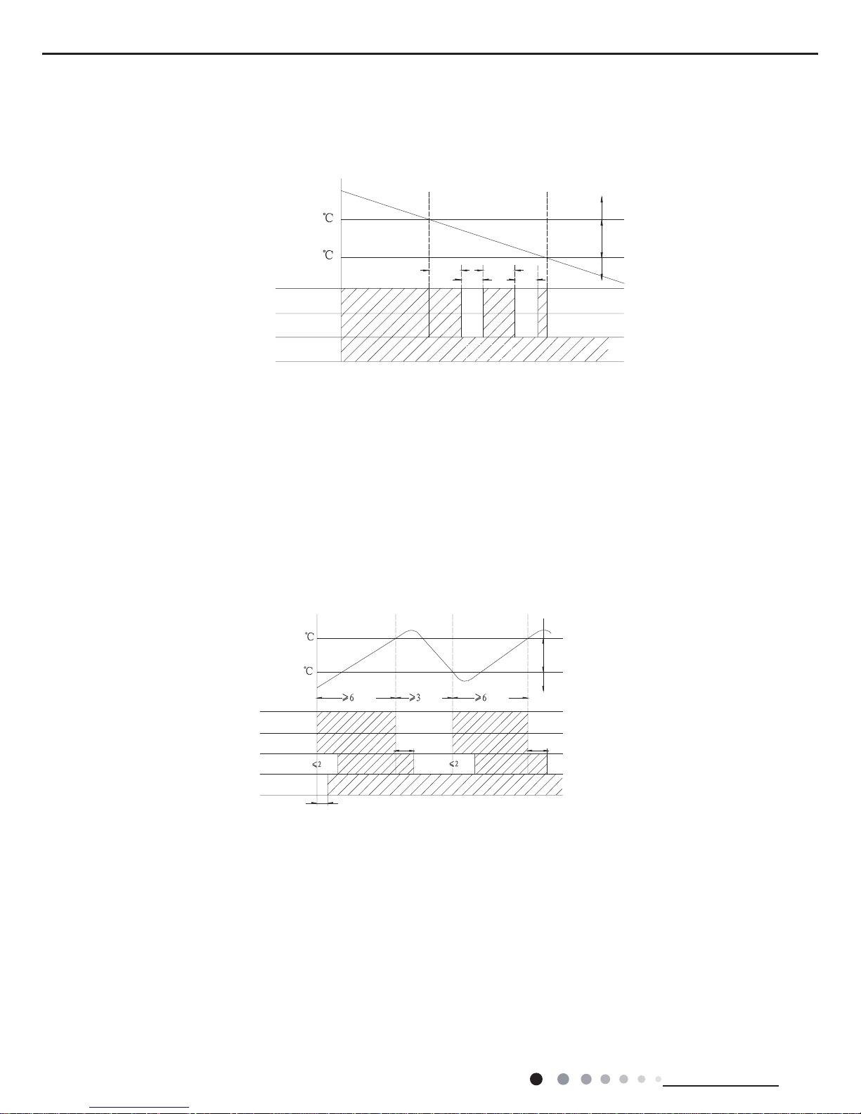
Service Manual
26
Technical Information
fan motor operates at low speed.
◆
When Tamb.<Tset-2℃, the compressor and the ODU fan motor stop, while the IDU fan motor runs at low speed.
In drying mode, the 4-way valve is de-energized (4-way valve is not available for cooling only unit); Temperature setting range is
16~30℃. Fan speed can’t be adjusted.
②
Protection functions (See function protection of this section)
(4)Heating mode(heating mode is not available for cooling only uni)
①
Operation condition and process
◆
When Tamb.≤Tset-1℃, the system starts heating operation. In this case, the 4-way valve is energized. The compressor and the
ODU fan motor operates simultaneously; The IDU fan motor will be started up after delayed for a period of time to make sure the air
conditioner won’t blow out cold wind.
◆
When Tpreset-1
℃<
Tamb.<Tpreset+1℃, the system keeps previous operation status.
◆
When Tamb.≥Tpreset+1℃, the compressor and the ODU fan motor stop. The 4-way valve is energized all the time. The IDU fan
motor will blow residual heat after operating at set speed for a period of time consecutively to make sure the inner temperature of air
conditioner won’t be too high.
In heating mode, 4-way valve is energized. Temperature setting range is 16~30℃.
②
Defrosting condition and process
In order to ensure heating effect, the unit will proceed defrosting automatically according to the frost situation of outdoor unit. Dual-8
nixie tube displays H1 during defrosting. (For some models, heating icon is bright for a period of time and then OFF).
③
Protection functions (See function protection of this section)
(5) Fan mode
①
Operation condition and process
The IDU fan motor operates at set speed, while the compressor, the ODU fan motor and 4-way valve stop.
②
Protection functions (See function protection of this section)
10S
20S
10S
T
preset
+1
T
preset
-1
Stop heating
Original operating status
Start heating
valve
Outdoor unit
Intdoor unit
Compressor
min.
min.
min.
T
amb
.
.nim.nim
Set fan speedSet fan speed
Reversing
T
preset
T
amb.
+2
T
preset-
2
Cooling
Drying
Stop
6 min
6min.
4min.
4min.
Compressor
Low speed
Outdoor fan motor
Indoor fan motor
 Loading...