

Gree GUHD18NK3FO, GUHD36NK3FO, GUHD30NK3FO, GUHD24NK3FO, GUHD36NM3FO Service Manual
...
T1/R410A/50Hz
(GC201509 -
І
)
U-MATCH
Ⅳ
SERIES DC INVERTER AIR
CONDITIONERS SERVICE MANUAL

CONTENTS
PRODUCT .......................................................................................................................................................................... 2
1 MODELS LIST .............................................................................................................................................................. 2
1.1 Outdoor Unit .......................................................................................................................................................... 2
1.2 Indoor Unit ............................................................................................................................................................ 3
2 NOMENCLATURE ....................................................................................................................................................... 4
2.1 Outdoor Unit .......................................................................................................................................................... 4
2.2 Intdoor Unit ........................................................................................................................................................... 4
3 PRODUCT DATA .......................................................................................................................................................... 5
3.1 Product Data of Indoor Unit................................................................................................................................... 5
3.2 Operation Range ................................................................................................................................................. 14
3.3 Electrical Data ..................................................................................................................................................... 14
4 PIPING DIAGRAM ...................................................................................................................................................... 15
CONTROL ......................................................................................................................................................................... 18
1 OPERATION FLOWCHART ....................................................................................................................................... 18
1.1 Cooling/Dry Operation ........................................................................................................................................ 18
1.2 Heating Operation ................................................................................................................................ ............... 19
2 WIRELESS REMOTE CONTROLLER ....................................................................................................................... 20
2.1 Operation and Display View ................................................................................................................................ 20
3 WIRED CONTROLLER .............................................................................................................................................. 22
3.1 Display View ....................................................................................................................................................... 22
3.2 Operation View ................................................................................................................................................... 25
4 OPERATION INSTRUCTION OF SPECIAL FUNCTIONS .......................................................................................... 28
4.1 Setting of Filter Clean Reminder Function .......................................................................................................... 28
4.2 Low Temperature Drying Function ...................................................................................................................... 30
4.3 Lock Function...................................................................................................................................................... 30
4.4 Memory Function ................................................................................................................................................ 30
4.5 Door Control Function/Human Sensitive Function .............................................................................................. 30
4.6 Switch between Fahrenheit and Centigrade ....................................................................................................... 30
4.7 Enquiry of Ambient Temperature ........................................................................................................................ 31
4.8 Enquiry of Historical Malfunction ......................................................................................................................... 31
4.9 Debugging Function ................................................................ ............................................................................ 31
5 INSTALLATION OF WIRED CONTROLLER .............................................................................................................. 34
5.1 Standard Accessories ......................................................................................................................................... 34
5.2 Installation Position and Requirement ................................................................................................................. 35
5.3 Installation of Wired Controller ............................................................................................................................ 35
5.4 Removal of Wired Controller ............................................................................................................................... 36
6 TROUBLESHOOTING ............................................................................................................................................... 36
6.1 Display of Error Code .......................................................................................................................................... 36
7 CENTRALIZED CONTROLLER ................................................................................................................................. 38
7.1 Smart Zone Controller ......................................................................................................................................... 38
7.2 Additional Special Functions ............................................................................................................................... 40
INSTALLATION ................................................................................................................................................................. 55
1 INDOOR UNIT INSTALLATION.................................................................................................................................. 55
1.1 Installation of Duct Type ...................................................................................................................................... 55
1.2 Installation of Floor Ceiling Type ......................................................................................................................... 64
1.3 Installation of Cassette Type ............................................................................................................................... 71
2 OUTDOOR UNIT INSTALLATION .............................................................................................................................. 80
2.1 Before Installation ............................................................................................................................................... 80
2.2 Installation Site .................................................................................................................................................... 80
2.3 Caution for Installation ........................................................................................................................................ 81
2.4 Dimension Data .................................................................................................................................................. 82
3 REFRIGERATION PIPING WORK ............................................................................................................................. 83
3.1 Refrigeration Piping Work Procedures and Caution in Connecting ..................................................................... 83
3.2 Specification of Connection Pipe ........................................................................................................................ 87
4 ELECTRIC WIRING WORK ....................................................................................................................................... 88
4.1 Wiring Precautions .............................................................................................................................................. 88
4.2 Electrical Wiring .................................................................................................................................................. 88
MAINTENANCE ................................................................................................................................................................ 94
1 TROUBLE TABLE ...................................................................................................................................................... 94
1.1Main Control Malfunction ..................................................................................................................................... 94
2 FLOW CHART OF TROUBLESHOOTING ................................................................................................................. 97
2.1 Troubleshooting Flow Chart of Main Control Malfunction .................................................................................... 97
2.2 Troubleshooting Flow Chart of Drive Malfunction .............................................................................................. 104
2.3 Interface ............................................................................................................................................................ 109
2.4 IPM, PFC Testing Method ................................................................................................................................. 114
3 WIRING DIADRAM ................................................................................................................................................... 118

3.1 Outdoor unit ...................................................................................................................................................... 118
3.2 Indoor unit ......................................................................................................................................................... 123
4 DISASSEMBLY AND ASSEMBLY PROCEDURE OF MAIN PARTS ......................................................................... 127
4.1 Outdoor Unit ...................................................................................................................................................... 127
4.2 Indoor Unit ........................................................................................................................................................ 133
5 EXPLODED VIEWS AND SPARE PART LIST .......................................................................................................... 146
5.1 Outdoor Unit ...................................................................................................................................................... 146
5.2 Indoor Unit ........................................................................................................................................................ 158

U-Match Series DC Inverter Service Manual
1
PRODUCT
U-Match Series DC Inverter Service Manual
2
PRODUCT
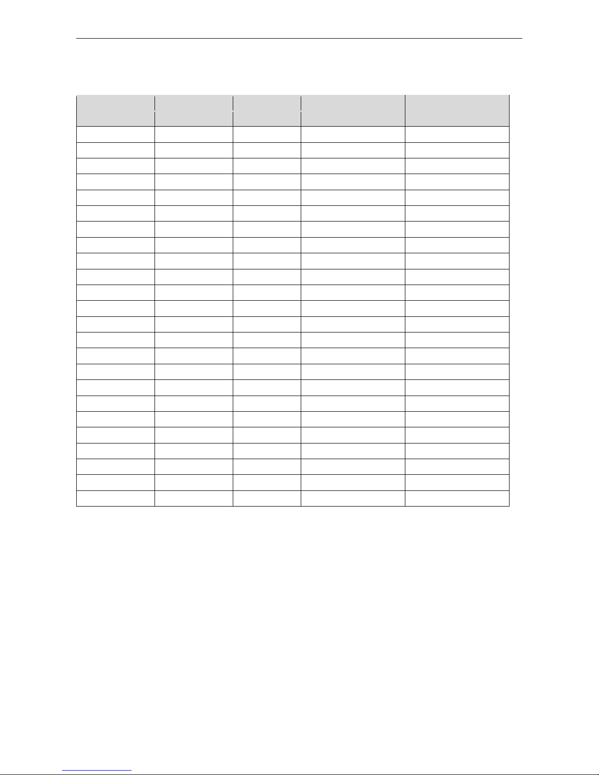
1 MODELS LIST
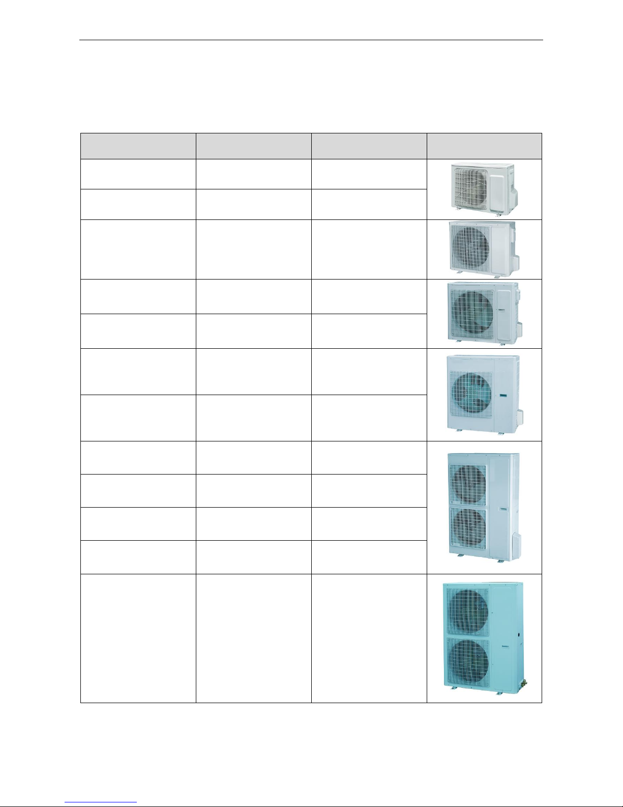
1.1 Outdoor Unit
Model Name
Product Code
Power Supply
(V, Ph, Hz)
Appearance
GUHD09NK3FO
CF090W0630
220-240V~ 50Hz
GUHD12NK3FO
CF090W0640
220-240V~ 50Hz
GUHD18NK3FO
CF090W0650
220-240V~ 50Hz
GUHD24NK3FO
CF090W0660
220-240V~ 50Hz
GUHD30NK3FO
CF090W0670
220-240V~ 50Hz
GUHD36NK3FO
CF090W0680
220-240V~ 50Hz
GUHD36NM3FO
CF090W0690
380-415V 3N~ 50Hz
GUHD42NK3FO
CF090W0700
220-240V~ 50Hz
GUHD42NM3FO
CF090W0710
380-415V~ 3N 50Hz
GUHD48NK3FO
CF090W0720
220-240V~ 50Hz
GUHD48NM3FO
CF090W0730
380-415V 3N~ 50Hz
GUHD60NM3FO
CF090W0740
380-415V 3N~ 50Hz
U-Match Series DC Inverter Service Manual
3
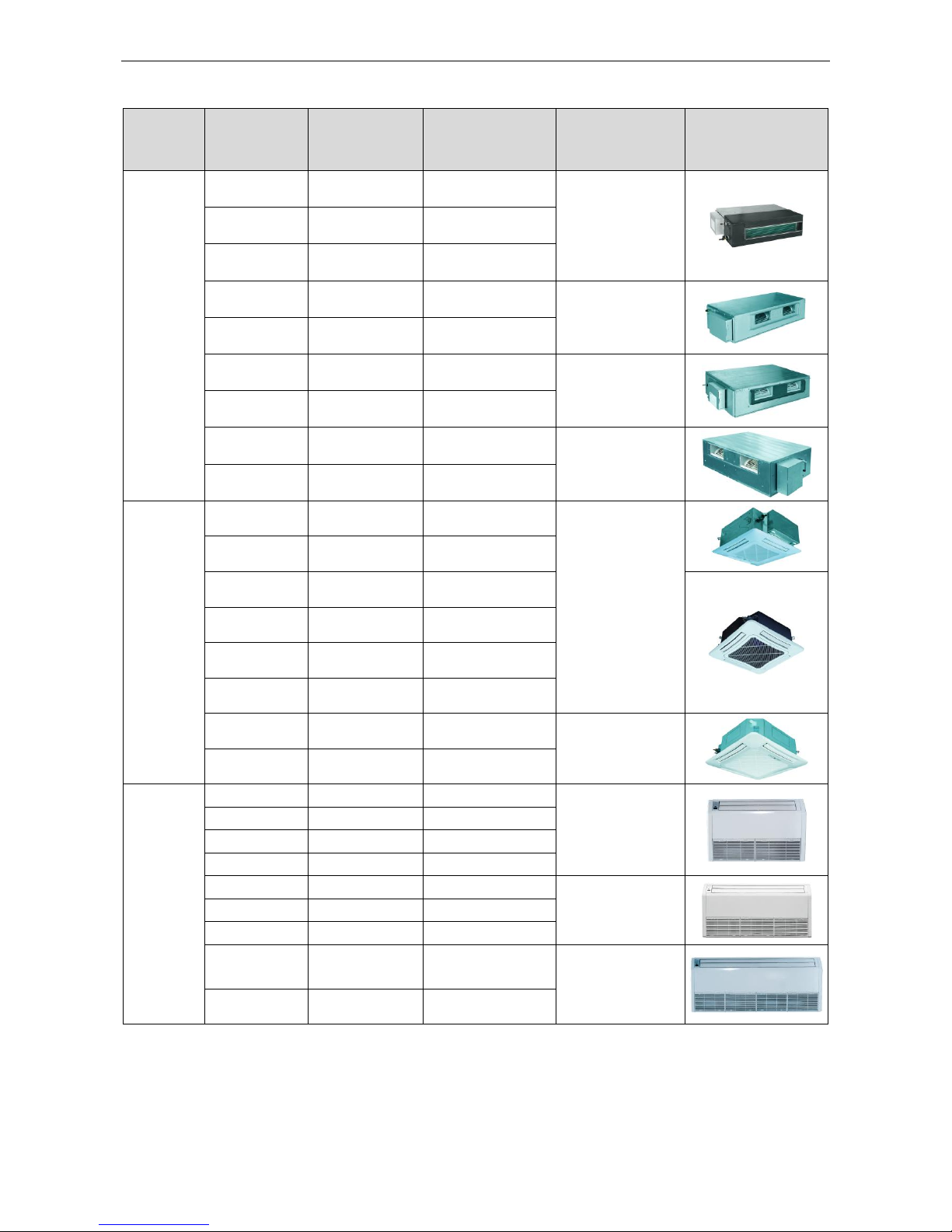
1.2 Indoor Unit
Type
Model Name
Product Code
Nominal Capacity
Cooling/Heating
(kW)
Power
Supply
(V, Ph, Hz)
Appearance
Duct
Type
GFH09K3FI
CF060N0420
2.7/2.9
220-240V~ 50Hz
GFH12K3FI
CF060N0430
3.5/3.8
GFH18K3FI
CF060N0440
5.0/5.6
GFH24K3FI
CF060N0450
7.0/8.0
220-240V~ 50Hz
GFH30K3FI
CF060N0460
8.3/9.2
GFH36K3FI
CF060N0470
10.0/12.0
220-240V~ 50Hz
GFH42K3FI
CF060N0480
11.5/13.5
GFH48K3FI
CF060N0490
14.0/15.5
220-240V~ 50Hz
GFH60K3FI
CF060N0500
16.0/17.5
Cassette
Type
GKH12K3FI
ET010N0670
3.5/3.8
220-240V~ 50Hz
GKH18K3FI
ET010N0680
5.0/5.5
GKH24K3FI
ET010N0690
7.0/8.0
GKH30K3FI
ET010N0740
8.3/9.2
GKH36K3FI
ET010N0700
10.0/12.0
GKH42K3FI
ET010N0710
11.0/12.5
GKH48K3FI
ET010N0720
14.0/16.0
220-240V~
50Hz
GKH60K3FI
ET010N0730
16.0/17.0
Ceiling
Type
GTH09K3FI
ED020N0650
2.7/2.9
220-240V~ 50Hz
GTH12K3FI
ED020N0660
3.5/3.8
GTH18K3FI
ED020N0670
5.0/5.6
GTH24K3FI
ED020N0680
7.0/8.0
GTH30K3FI
ED020N0690
8.5/9.2
220-240V~
50Hz
GTH36K3FI
ED020N0700
10.0/12.0
GTH42K3FI
ED020N0710
11.5/13.5
GTH48K3FI
ED020N0720
14.0/16.0
220-240V~
50Hz
GTH60K3FI
ED020N0730
16.0/17.0
Note:1 Ton =12000Btu/h = 3.517kW
Notes: The universal outdoor units means that the customer can choose any of three kind of indoor unit
to match the outdoor unit without any change with it.
U-Match Series DC Inverter Service Manual
4
2 NOMENCLATURE
2.1 Outdoor Unit
G U H D 09 N K 3 F
O
1 2 3 4 5 6 7 8 9
10
NO.
Description
Options
1
Gree Electric Appliances Inc
Capital Letter :G 2 Unit Type
U=U-Match Outdoor Unit
3
Product Type
C=Cool Only
H=Heat Pump without Aux Electric Heaters
4
Compressor Power Supply
Type Code
N=Constant Frequency
D=DC Inverter
A=AC Inverter
5
Nominal Cooling Capacity
Nominal Cooling Capacity
=Number×1000Btu/h
6
Climate Type
N=Climate T1 Condition
T= Climate T3 Condition
7
Power Supply Code
K= 220-240V~ 50Hz
M=380-415V 3N~ 50Hz
8
Refrigerant
1 =R22; 2=R407C; 3=R410A
9
Design Code
Design Code: A, B, C, D……
Design Change Code=0 (default)
1,2,3......
10
Unit Code
O=Outdoor unit
2.2 Intdoor Unit
G F H
09 T K 3 F
I
1 2 3 4 5 6 7 8 9
NO.
Description
Options
1
Gree Electric Appliances Inc
Capital Letter :G
2
Unit Type
F=Duct Type; K=Cassette Type; T= Floor-ceiling Type
3
Product Type
C=Cool Only
H=Heat Pump without Aux Electric Heaters
4
Nominal Cooling Capacity
Nominal Cooling Capacity
=Number×1000Btu/h
5
Climate Type
Omit=Climate T1 Condition
T= Climate T3 Condition
6
Power Supply Code
K= 220-240V~ 50Hz
M=380-415V 3N~ 50Hz
7
Refrigerant
1 =R22; 2=R407C; 3=R410A
8
Design Code
Design Code: A, B, C, D……
Design Change Code=0 (default)
1,2,3......
9
Unit Code
I=indoor unite
U-Match Series DC Inverter Service Manual
5
3 PRODUCT DATA
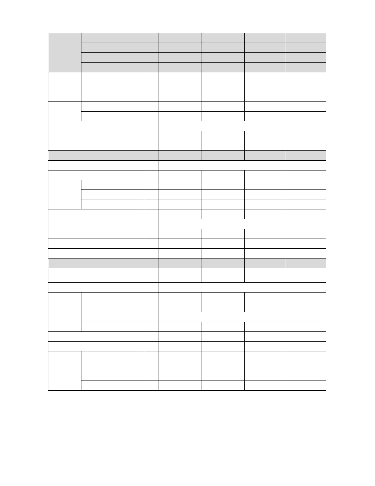
3.1 Product Data of Indoor Unit
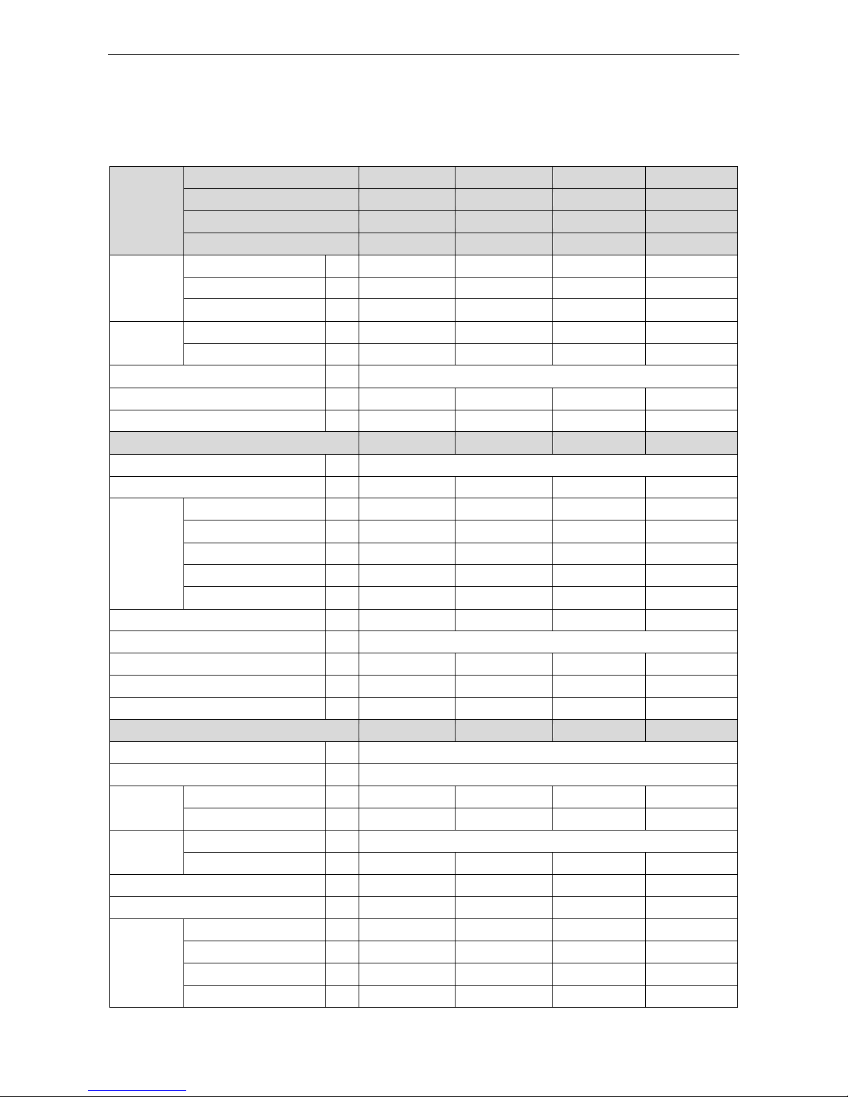
3.1.1 Duct Type
Model
Indoor unit
GFH09K3FI
GFH12K3FI
GFH18K3FI
GFH24K3FI
Product Code
CF060N0420
CF060N0430
CF060N0440
CF060N0450
Outdoor unit
GUHD09NK3FO
GUHD12NK3FO
GUHD18NK3FO
GUHD24NK3FO
Product Code
CF090W0630
CF090W0640
CF090W0650
CF090W0660
Capacity
Cooling Capacity
kW
2.7(0.80-3.40)
3.5(0.90-3.70)
5.0(1.60-5.50)
7.0(2.20-8.500)
Heating Capacity
kW
2.9(0.80-3.70)
3.8(0.90-4.10)
5.6(1.40-6.80)
8.0(2.40-9.50)
PdesignH
kW
2.8
3.0
4.5
7.0
Power Input
Cooling
kW
0.84(0.20-1.28)
1.17(0.20-1.40)
1.60(0.55-1.75)
2.18(0.85-2.50)
Heating
kW
0.80(0.20-1.20)
1.05(0.22-1.20)
1.58(0.50-1.90)
2.21(0.80-2.75)
Design load Average
SEER / SCOP
W/W
5.6/3.8
5.6/4.0
5.6/3.8
6.1/4.0
Energy Rate(Cooling / Heating)
A+/A
A+/A+
A+/A
A++/A+
Indoor Unit
GFH09K3FI
GFH12K3FI
GFH18K3FI
GFH24K3FI
Power Supply 220-240V~ 50Hz
Heat Exchange
Cross Fin Coil
Cross Fin Coil
Cross Fin Coil
Cross Fin Coil
Fan
Drive
direct
direct
direct
direct
Motor Output
kW
0.04×1
0.05×1
0.07×1
0.11×1
Air Flow
m3/h
650
750
1000
1400
Rated Ext. Static Pressure
Pa
25
25
25
25
Ext. Static Pressure Range
Pa
0~30
0~30
0~30
0~100
Sound Pressure Level(SS/H/M/L)
dB(A)
36/34/28/26
37/36/34/28
40/39/36/28
47/46/44/40
Air Filter Standard washable synthetic
Drain
mm
Φ20×1.2
Φ30×1.5
Φ30×1.5
Φ20×1.2
Outline Dimensions (W×H×D)
mm
925×250×665
1035×265×720
1035×265×720
1280×270×560
Net Weight
kg
27
33
33
34
Outdoor Unit
GUHD09NK3FO
GUHD12NK3FO
GUHD18NK3FO
GUHD24NK3FO
Power Supply 220-240V~ 50Hz
Heat Exchange Cross Fin Coil
Compressor
Type
Rotary
Rotary
Rotary
Rotary
Power Input
W
942
942
1440
2550
Refrigerant
Control Electronic Expansion Valve
Charge
kg
1.2
1.2
1.4
2.2
Outline Dimensions (W×H×D)
mm
850×540×320
850×540×320
955×700×395
980×790×425
Net Weight
kg
34
34
47
67
Piping
Connections
Liquid
Inch
Φ1/4
Φ1/4
Φ1/4
Φ3/8
Gas
Inch
Φ3/8
Φ3/8
Φ1/2
Φ5/8
Max. Length
m
20
20
20
30
Max. Height
m
15
15
15
15
U-Match Series DC Inverter Service Manual
6
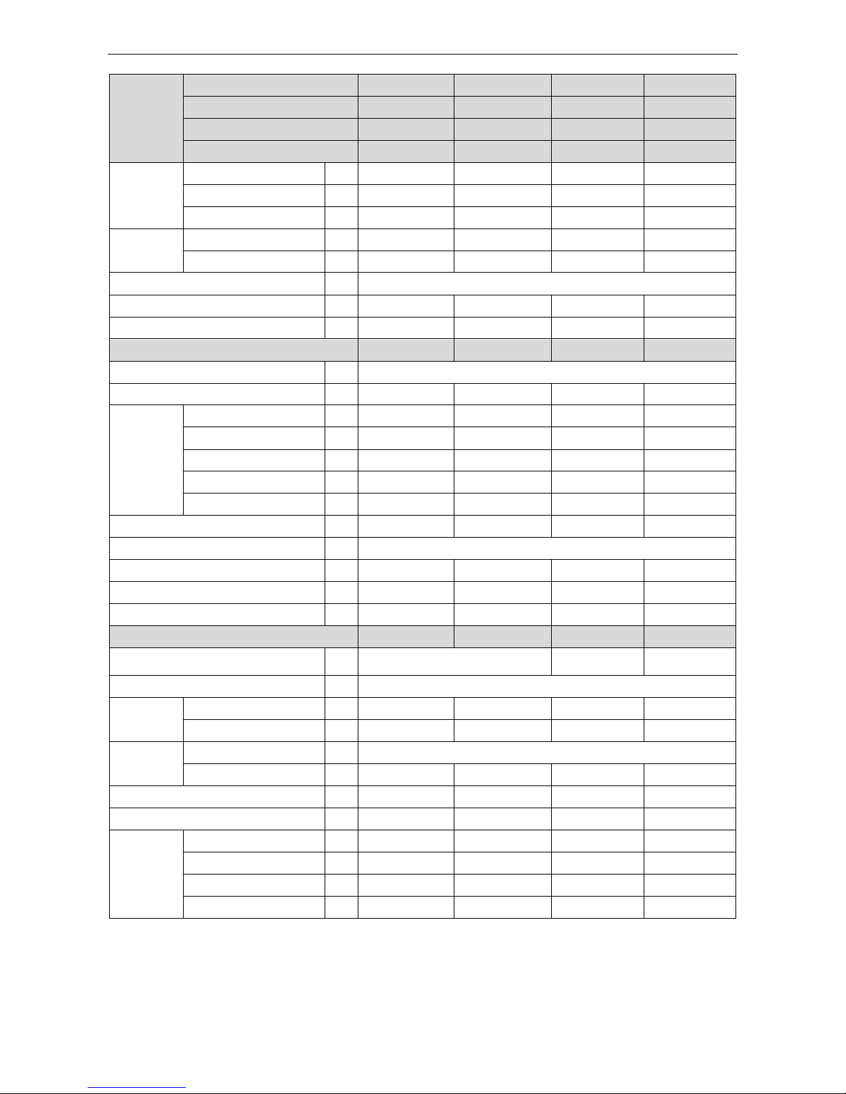
Model
Indoor unit
GFH30K3FI
GFH36K3FI
GFH36K3FI
GFH42K3FI
Product Code
CF060N0460
CF060N0470
CF060N0470
CF060N0480
Outdoor unit
GUHD30NK3FO
GUHD36NK3FO
GUHD36NM3FO
GUHD42NK3FO
Product Code
CF090W0670
CF090W0680
CF090W0690
CF090W0700
Capacity
Cooling Capacity
kW
8.3(2.40-8.70)
10.0(3.20-11.50)
10.0(3.20-11.50)
11.5(3.60-12.50)
Heating Capacity
kW
9.2(2.40-9.90)
12.0(2.90-14.50)
12.0(2.90-14.50)
13.5(3.90-15.50)
PdesignH
kW
7.6
10.4
10.4
10.5
Power Input
Cooling
kW
2.67(0.85-2.70)
3.20(0.70-4.50)
3.20(0.70-4.50)
4.00(0.65-4.70)
Heating
kW
2.57(0.80-2.86)
3.40(0.70-4.60)
3.40(0.70-4.60)
3.90(0.76-4.75)
Design load Average
SEER / SCOP
W/W
6.1/4.0
5.6/4.0
5.1/4.0
5.6/3.8
Energy Rate(Cooling / Heating)
A++/A+
A+/A+
A/A+
A+/A
Indoor Unit
GFH30K3FI
GFH36K3FI
GFH36K3FI
GFH42K3FI
Power Supply 220-240V~ 50Hz
Heat Exchange
Cross Fin Coil
Cross Fin Coil
Cross Fin Coil
Cross Fin Coil
Fan
Drive
direct
direct
direct
direct
Motor Output
kW
0.11×1
0.23×1
0.23×1
0.23×1
Air Flow
m3/h
1400
2100
2100
2100
Rated Ext. Static Pressure
Pa
37
37
37
37
Ext. Static Pressure Range
Pa
0~100
0~150
0~150
0~150
Sound Pressure Level(SS/H/M/L)
dB(A)
47/46/44/40
53/52/48/44
53/52/48/44
53/52/48/44
Air Filter Standard washable synthetic
Drain Piping
mm
Φ20×1.2
Φ20×1.2
Φ20×1.2
Φ20×1.2
Outline Dimensions (W×H×D)
mm
1280×270×560
1225×290×775
1225×290×775
1225×290×775
Net Weight
kg
34
46
46
46
Outdoor Unit
GUHD30NK3FO
GUHD36NK3FO
GUHD36NM3FO
GUHD42NK3FO
Power Supply
220-240V~ 50Hz
380-415V 3N~
50Hz
220-240V~ 50Hz
Heat Exchange Cross Fin Coil
Compressor
Type
Rotary
Rotary
Rotary
Rotary
Power Input
W
2550
4150
4000
4150
Refrigerant
Control Electronic Expansion Valve
Charge
kg
2.4
3.5
3.5
3.7
Outline Dimensions (W×H×D)
mm
980×790×425
1105×1100×440
1105×1100×440
960×1350×410
Net Weight
kg
71
92
98
95
Piping
Connections
Liquid
Inch
Φ3/8
Φ3/8
Φ3/8
Φ3/8
Gas
Inch
Φ5/8
Φ5/8
Φ5/8
Φ5/8
Max. Length
m
30
30
30
50
Max. Height
m
15
15
15
30
U-Match Series DC Inverter Service Manual
7
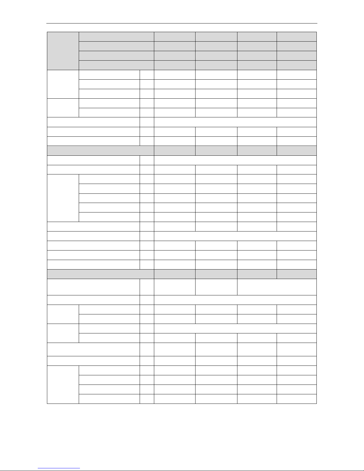
Model
Indoor unit
GFH42K3FI
GFH48K3FI
GFH48K3FI
GFH60K3FI
Product Code
CF060N0480
CF060N0490
CF060N0490
CF060N0500
Outdoor unit
GUHD42NM3FO
GUHD48NK3FO
GUHD48NM3FO
GUHD60NM3FO
Product Code
CF090W0710
CF090W0720
CF090W0730
CF090W0740
Capacity
Cooling Capacity
kW
11.5(3.60-12.50)
14.0(6.00-14.50)
14.0(6.00-14.50)
16.0(7.4~16.5)
Heating Capacity
kW
13.5(3.90-15.50)
15.5(5.20-17.00)
15.5(5.20-17.00)
16.5(6.2~18.5)
PdesignH
kW
10.5
11.8
11.8
12.5
Power Input
Cooling
kW
4.00(0.65-4.70)
4.70(1.40-5.60)
5.10(1.40-5.60)
5.60(1.20-6.90)
Heating
kW
3.90(0.76-4.75)
4.40(1.30-5.50)
4.50(1.30-5.50)
4.60(1.20-6.90)
Design load Average
SEER / SCOP
W/W
5.6/4.0
6.1/3.8
5.6/3.8
5.6/3.8
Energy Rate(Cooling / Heating)
A+/A+
A++/A
A+/A
A+/A
Indoor Unit
GFH42K3FI
GFH48K3FI
GFH48K3FI
GFH60K3FI
Power Supply 220-240V~ 50Hz
Heat Exchange
Cross Fin Coil
Cross Fin Coil
Cross Fin Coil
Cross Fin Coil
Fan
Drive
direct
direct
direct
direct
Motor Output
kW
0.23×1
0.25×1
0.25×1
0.28×1
Air Flow
m3/h
2100
2400
2400
3000
Rated Ext. Static Pressure
Pa
37
50
50
50
Ext. Static Pressure Range
Pa
0~150
0~150
0~150
0~150
Sound Pressure Level(SS/H/M/L)
dB(A)
53/52/48/44
55/53/49/45
55/53/49/45
57/56/54/49
Air Filter Standard washable synthetic
Drain Piping
mm
Φ20×1.2
Φ20×1.2
Φ20×1.2
Φ20×1.2
Outline Dimensions (W×H×D)
mm
1225×290×775
1340×350×750
1340×350×750
1340×350×750
Net Weight
kg
46
56
56
56
Outdoor Unit
GUHD42NM3FO
GUHD48NK3FO
GUHD48NM3FO
GUHD60NM3FO
Power Supply
380-415V 3N~
50Hz
220-240V~ 50Hz
380-415V 3N~ 50Hz
Heat Exchange Cross Fin Coil
Compressor
Type
Rotary
Rotary
Rotary
Rotary
Power Input
W
4000
4580
4580
4580
Refrigerant
Control Electronic Expansion Valve
Charge
kg
3.7
4.0
4.0
5.0
Outline Dimensions (W×H×D)
mm
960×1350×410
960×1350×410
960×1350×410
1085×1365×425
Net Weight
kg
108
105
114
126
Piping
Connections
Liquid
Inch
Φ3/8
Φ3/8
Φ3/8
Φ3/8
Gas
Inch
Φ5/8
Φ5/8
Φ5/8
Φ3/4
Max. Length
m
50
50
50
50
Max. Height
m
30
30
30
30
U-Match Series DC Inverter Service Manual
8
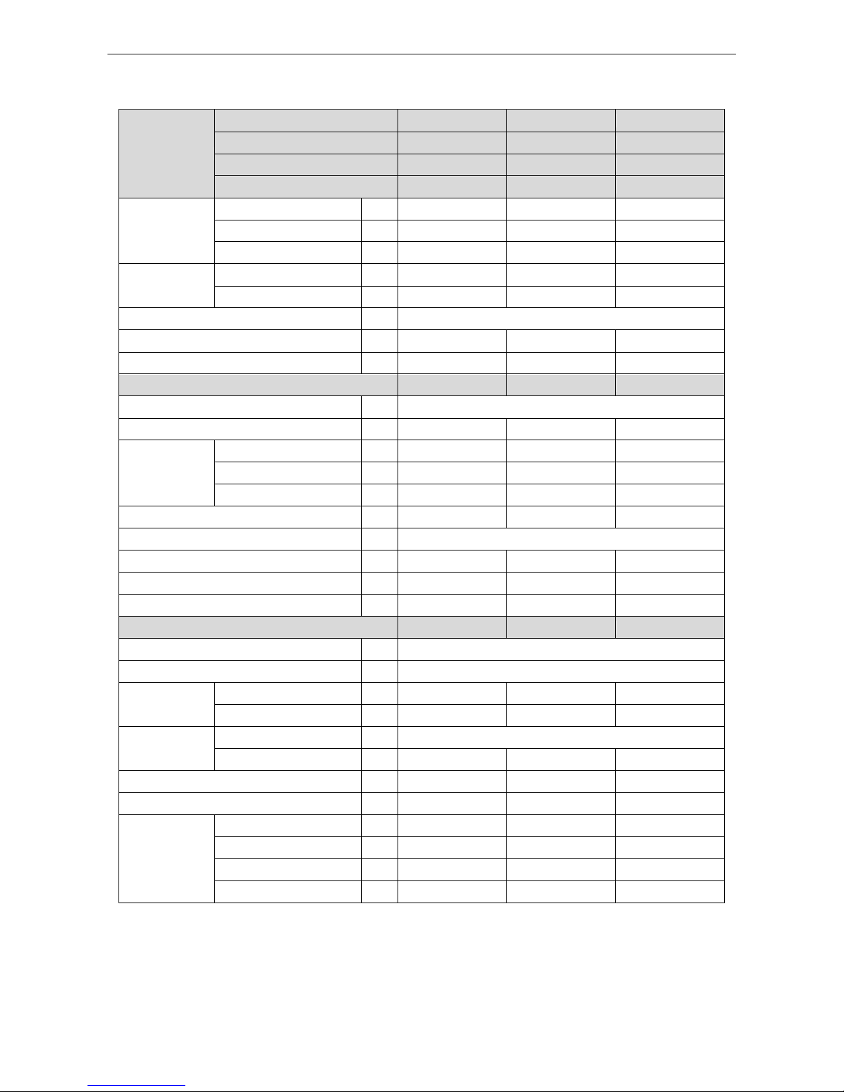
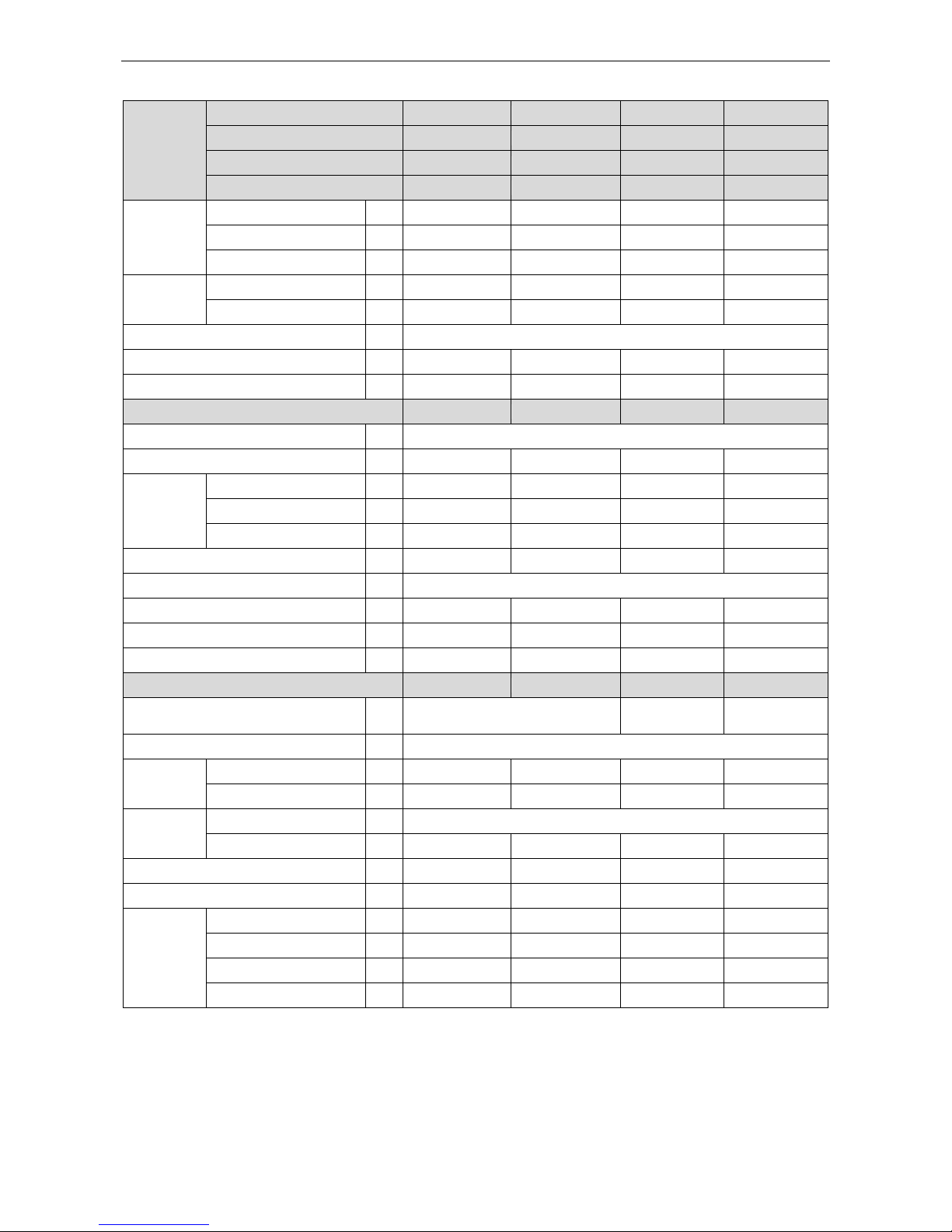
3.1.2 Cassette Type
Model
Indoor unit
GKH12K3FI
GKH18K3FI
GKH24K3FI
Product Code
ET010N0670
ET010N0680
ET010N0690
Outdoor unit
GUHD12NK3FO
GUHD18NK3FO
GUHD24NK3FO
Product Code
CF090W0640
CF090W0650
CF090W0660
Capacity
Cooling Capacity
kW
3.5(0.90-3.90)
5.0(1.60-5.80)
7.0(2.40-8.50)
Heating Capacity
kW
3.8(0.90-4.10)
5.5(1.40-6.50)
8.0(2.40-9.50)
PdesignH
kW
3.0
4.5
7.2
Power Input
Cooling
kW
1.09(0.30-1.40)
1.55(0.55-1.75)
2.18(0.85-2.50)
Heating
kW
1.05(0.22-1.20)
1.64(0.50-1.90)
2.21(0.80-2.75)
Design load Average
SEER / SCOP
W/W
5.6/4.0
5.6/3.8
6.1/4.0
Energy Rate(Cooling / Heating)
A+/A+
A+/A
A++/A+
Indoor Unit
GKH12K3FI
GKH18K3FI
GKH24K3FI
Power Supply
220-240V~50Hz
Heat Exchange
Cross Fin Coil
Cross Fin Coil
Cross Fin Coil
Fan
Drive
direct
direct
direct
Motor Output
kW
0.03×1
0.04×1
0.065×1
Air Flow
m3/h
700
760
1300
Sound Pressure Level(SS/H/M/L)
dB(A)
46/45/41/36
47/46/44/37
47/46/42/38
Air Filter
Standard washable synthetic
Drain Piping
mm
Φ25×1.5
Φ25×1.5
Φ25×1.5
Outline Dimensions (W×H×D)
mm
595×240×595
595×240×595
840×240×840
Net Weight
kg
20
20
26
Outdoor Unit
GUHD12NK3FO
GUHD18NK3FO
GUHD24NK3FO
Power Supply
220-240V~50Hz
Heat Exchange
Cross Fin Coil
Compressor
Type
Rotary
Rotary
Rotary
Power Input
W
942
1440
2550
Refrigerant
Control Electronic Expansion Valve
Charge
kg
1.2
1.4
2.2
Outline Dimensions (W×H×D)
mm
850×540×320
955×700×395
980×790×425
Net Weight
kg
34
47
67
Piping
Connections
Liquid
Inch
Φ1/4
Φ1/4
Φ3/8
Gas
Inch
Φ3/8
Φ1/2
Φ5/8
Max. Length
m
20
20
30
Max. Height
m
15
15
15

U-Match Series DC Inverter Service Manual
9
Model
Indoor unit
GKH30K3FI
GKH36K3FI
GKH36K3FI
GKH42K3FI
Product Code
ET010N0740
ET010N0700
ET010N0700
ET010N0710
Outdoor unit
GUHD30NK3FO
GUHD36NK3FO
GUHD36NM3FO
GUHD42NK3FO
Product Code
CF090W0670
CF090W0680
CF090W0690
CF090W0700
Capacity
Cooling Capacity
kW
8.3(2.60-9.20)
10.0(3.20-11.50)
10.0(3.20-11.50)
11.0(3.30-12.00)
Heating Capacity
kW
9.2(2.40-9.90)
12.0(2.90-14.50)
12.0(2.90-14.50)
12.5(3.60-15.00)
PdesignH
kW
7.6
10.4
10.4
9.5
Power Input
Cooling
kW
2.67(0.85-2.70)
3.20(0.75-4.50)
3.20(0.75-4.50)
3.90(0.53-4.65)
Heating
kW
2.57(0.80-2.86)
3.50(0.60-4.80)
3.50(0.60-4.80)
3.80(0.64-4.80)
Design load Average
SEER / SCOP
W/W
6.1/4.0
6.1/4.0
6.1/4.0
5.6/4.0
Energy Rate(Cooling / Heating)
A++/A+
A++/A+
A++/A+
A+/A+
Indoor Unit
GKH30K3FI
GKH36K3FI
GKH36K3FI
GKH42K3FI
Power Supply 220-240V~ 50Hz
Heat Exchange
Cross Fin Coil
Cross Fin Coil
Cross Fin Coil
Cross Fin Coil
Fan
Drive
direct
direct
direct
direct
Motor Output
kW
0.065×1
0.11×1
0.11×1
0.11×1
Air Flow
m3/h
1500
1860
1860
1860
Sound Pressure Level(SS/H/M/L)
dB(A)
49/48/45/40
51/49/46/43
51/49/46/43
51/49/46/43
Air Filter Standard washable synthetic
Drain Piping
mm
Φ25×1.5
Φ25×1.5
Φ25×1.5
Φ25×1.5
Outline Dimensions (W×H×D)
mm
840×320×840
840×320×840
840×320×840
840×320×840
Net Weight
kg
31
31
31
31
Outdoor Unit
GUHD30NK3FO
GUHD36NK3FO
GUHD36NM3FO
GUHD42NK3FO
Power Supply
220-240V~ 50Hz
380-415V 3N~
50Hz
220-240V~ 50Hz
Heat Exchange Cross Fin Coil
Compressor
Type
Rotary
Rotary
Rotary
Rotary
Power Input
W
2550
4150
4000
4150
Refrigerant
Control Electronic Expansion Valve
Charge
kg
2.4
3.5
3.5
3.7
Outline Dimensions (W×H×D)
mm
980×790×425
1105×1100×440
1105×1100×440
960×1350410
Net Weight
kg
71
92
98
95
Piping
Connections
Liquid
Inch
Φ3/8
Φ3/8
Φ3/8
Φ3/8
Gas
Inch
Φ5/8
Φ5/8
Φ5/8
Φ5/8
Max. Length
m
30
30
30
50
Max. Height
m
15
15
15
30
U-Match Series DC Inverter Service Manual
10
Model
Indoor unit
GKH42K3FI
GKH48K3FI
GKH48K3FI
GKH60K3FI
Product Code
ET010N0710
ET010N0720
ET010N0720
ET010N0730
Outdoor unit
GUHD42NM3FO
GUHD48NK3FO
GUHD48NM3FO
GUHD60NM3FO
Product Code
CF090W0710
CF090W0720
CF090W0730
CF090W0740
Capacity
Cooling Capacity
kW
11.0(3.30-12.00)
14.0(6.00-14.80)
14.0(6.00-14.80)
16.0(7.4~16.5)
Heating Capacity
kW
12.5(3.60-15.00)
16.0(5.20-18.00)
16.0(5.20-18.00)
16.5(6.2~18.5)
PdesignH
kW
9.5
12.0
12.0
12.5
Power Input
Cooling
kW
3.90(0.53-4.65)
4.60(1.30-5.50)
4.60(1.30-5.50)
5.70(1.20-6.90)
Heating
kW
3.80(0.64-4.80)
4.50(1.20-5.40)
4.50(1.20-5.40)
4.60(1.20-6.90)
Design load Average
SEER / SCOP
W/W
6.1/4.0
6.1/3.8
5.6/3.8
6.1/4.0
Energy Rate(Cooling / Heating)
A++/A+
A++/
A+/A
A++/A+
Indoor Unit
GKH42K3FI
GKH48K3FI
GKH48K3FI
GKH60K3FI
Power Supply 220-240V~ 50Hz
Heat Exchange
Cross Fin Coil
Cross Fin Coil
Cross Fin Coil
Cross Fin Coil
Fan
Drive
direct
direct
direct
direct
Motor Output
kW
0.11×1
0.15×1
0.15×1
0.17×1
Air Flow
m3/h
1860
2300
2300
2400
Sound Pressure Level(SS/H/M/L)
dB(A)
51/49/46/43
53/52/47/41
53/52/47/41
54/53/47/41
Air Filter Standard washable synthetic
Drain Piping
mm
Φ25×1.5
Φ25×1.5
Φ25×1.5
Φ25×1.5
Outline Dimensions (W×H×D)
mm
840×320×840
910×290×910
910×290×910
910×290×910
Net Weight
kg
31
43
43
43
Outdoor Unit
GUHD42NM3FO
GUHD48NK3FO
GUHD48NM3FO
GUHD60NM3FO
Power Supply
380-415V 3N~
50Hz
220-240V~ 50Hz
380-415V 3N~ 50Hz
Heat Exchange Cross Fin Coil
Compressor
Type
Rotary
Rotary
Rotary
Rotary
Power Input
W
4000
4580
4580
4580
Refrigerant
Control Electronic Expansion Valve
Charge
kg
3.7
4.0
4.0
5.0
Outline Dimensions (W×H×D)
mm
960×1350×410
960×1350×410
960×1350×410
1085×1365×425
Net Weight
kg
108
105
114
126
Piping
Connections
Liquid
Inch
Φ3/8
Φ3/8
Φ3/8
Φ3/8
Gas
Inch
Φ5/8
Φ5/8
Φ5/8
Φ3/4
Max. Length
m
50
50
50
50
Max. Height
m
30
30
30
30

U-Match Series DC Inverter Service Manual
11
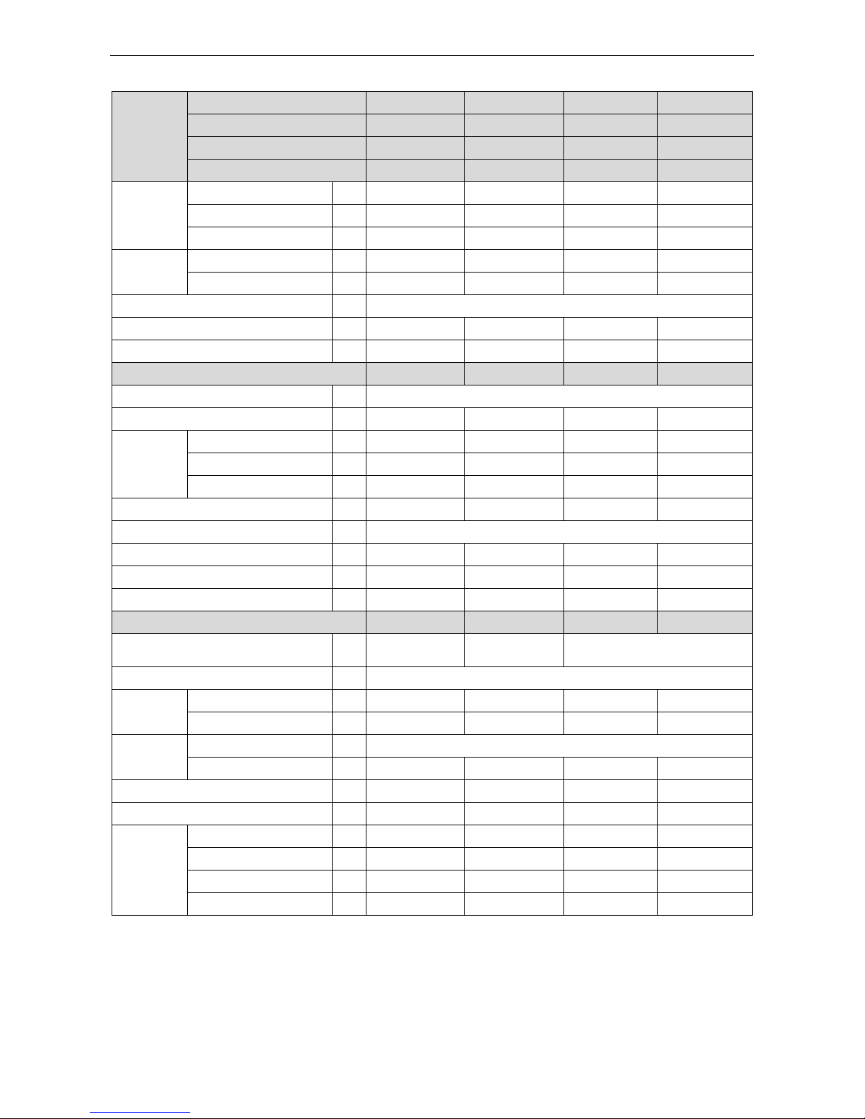
3.1.3 Floor-ceiling Type
Model
Indoor unit
GTH09K3FI
GTH12K3FI
GTH18K3FI
GTH24K3FI
Product Code
ED020N0650
ED020N0660
ED020N0670
ED020N0680
Outdoor unit
GUHD09NK3FO
GUHD12NK3FO
GUHD18NK3FO
GUHD24NK3FO
Product Code
CF090W0630
CF090W0640
CF090W0650
CF090W0660
Capacity
Cooling Capacity
kW
2.7(0.80-3.50)
3.5(0.90-3.90)
5.0(1.60-5.80)
7.0(2.40-8.20)
Heating Capacity
kW
2.9(0.80-3.80)
3.8(0.90-4.10)
5.6(1.40-6.80)
8.0(2.40-9.00)
PdesignH
kW
2.9
3.0
4.5
7.0
Power Input
Cooling
kW
0.84(0.20-1.28)
1.09(0.26-1.40)
1.55(0.55-1.75)
2.18(0.85-2.50)
Heating
kW
0.80(0.20-1.20)
1.05(0.22-1.20)
1.55(0.50-1.90)
2.21(0.80-2.75)
Design load Average
SEER / SCOP
W/W
6.1/3.8
6.1/4.0
6.1/4.0
5.6/4.0
Energy Rate(Cooling / Heating)
A++/A
A++/A+
A++/A+
A+/A+
Indoor Unit
GTH09K3FI
GTH12K3FI
GTH18K3FI
GTH24K3FI
Power Supply 220-240V~ 50Hz
Heat Exchange
Cross Fin Coil
Cross Fin Coil
Cross Fin Coil
Cross Fin Coil
Fan
Drive
direct
direct
direct
direct
Motor Output
kW
0.015×1
0.02×1
0.04×1
0.065×1
Air Flow
m3/h
600
700
1000
1200
Sound Pressure Level(SS/H/M/L)
dB(A)
31/29/26/24
35/33/30/27
44/42/38/32
49/48/46/40
Air Filter Standard washable synthetic
Drain Piping
mm
Φ17×1.75
Φ17×1.75
Φ17×1.75
Φ17×1.75
Outline Dimensions (W×H×D)
mm
1220×225×700
1220×225×700
1220×225×700
1220×225×700
Net Weight
kg
38
39
39
40
Outdoor Unit
GUHD09NK3FO
GUHD12NK3FO
GUHD18NK3FO
GUHD24NK3FO
Power Supply 220-240V~ 50Hz
Heat Exchange Cross Fin Coil
Compressor
Type
Rotary
Rotary
Rotary
Rotary
Power Input
W
942
942
1440
2550
Refrigerant
Control Electronic Expansion Valve
Charge
kg
1.2
1.2
1.4
2.2
Outline Dimensions (W×H×D)
mm
850×540×320
850×540×320
955×700×395
980×790×425
Net Weight
kg
34
34
47
67
Piping
Connections
Liquid
Inch
Φ1/4
Φ1/4
Φ1/4
Φ3/8
Gas
Inch
Φ3/8
Φ3/8
Φ1/2
Φ5/8
Max. Length
m
20
20
20
30
Max. Height
m
15
15
15
15
U-Match Series DC Inverter Service Manual
12
Model
Indoor unit
GTH30K3FI
GTH36K3FI
GTH36K3FI
GTH42K3FI
Product Code
ED020N0690
ED020N0700
ED020N0700
ED020N0710
Outdoor unit
GUHD30NK3FO
GUHD36NK3FO
GUHD36NM3FO
GUHD42NK3FO
Product Code
CF090W0670
CF090W0680
CF090W0690
CF090W0700
Capacity
Cooling Capacity
kW
8.5(2.60-9.20)
10.0(3.20-11.50)
10.0(3.20-11.50)
11.5(3.60-12.50)
Heating Capacity
kW
9.2(2.40-9.90)
12.0(2.90-14.50)
12.0(2.90-14.50)
13.5(3.90-15.50)
PdesignH
kW
7.6
10.4
10.4
10.5
Power Input
Cooling
kW
2.67(0.85-2.70)
3.20(0.80-4.60)
3.20(0.80-4.60)
3.90(0.60-4.70)
Heating
kW
2.57(0.80-2.86)
3.40(0.65-4.80)
3.40(0.65-4.80)
3.70(0.69-4.80)
Design load Average
SEER / SCOP
W/W
6.1/4.0
6.1/4.0
6.1/4.0
6.1/4.0
Energy Rate(Cooling / Heating)
A++/A+
A++/A+
A++/A+
A++/A+
Indoor Unit
GTH30K3FI
GTH36K3FI
GTH36K3FI
GTH42K3FI
Power Supply 220-240V~ 50Hz
Heat Exchange
Cross Fin Coil
Cross Fin Coil
Cross Fin Coil
Cross Fin Coil
Fan
Drive
direct
direct
direct
direct
Motor Output
kW
0.09×1
0.14×1
0.14×1
0.14×1
Air Flow
m3/h
1500
1900
1900
1900
Sound Pressure Level(SS/H/M/L)
dB(A)
49/46/44/38
54/53/51/46
54/53/51/46
55/54/52/47
Air Filter Standard washable synthetic
Drain Piping
mm
Φ17×1.75
Φ17×1.75
Φ17×1.75
Φ17×1.75
Outline Dimensions (W×H×D)
mm
1420×245×700
1420×245×700
1420×245×700
1420×245×700
Net Weight
kg
48
48
48
50
Outdoor Unit
GUHD30NK3FO
GUHD36NK3FO
GUHD36NM3FO
GUHD42NK3FO
Power Supply
220-240V~ 50Hz
380-415V 3N~
50Hz
220-240V~ 50Hz
Heat Exchange Cross Fin Coil
Compressor
Type
Rotary
Rotary
Rotary
Rotary
Power Input
W
2550
4150
4000
4150
Refrigerant
Control Electronic Expansion Valve
Charge
kg
2.4
3.4
3.5
3.7
Outline Dimensions (W×H×D)
mm
980×790×425
1105×1100×440
1105×1100×440
960×1350×410
Net Weight
kg
71
92
98
95
Piping
Connections
Liquid
Inch
Φ3/8
Φ3/8
Φ3/8
Φ3/8
Gas
Inch
Φ5/8
Φ5/8
Φ5/8
Φ5/8
Max. Length
m
30
30
30
50
Max. Height
m
15
15
15
30
U-Match Series DC Inverter Service Manual
13
Model
Indoor unit
GTH42K3FI
GTH48K3FI
GTH48K3FI
GTH60K3FI
Product Code
ED020N0710
ED020N0720
ED020N0720
ED020N0730
Outdoor unit
GUHD42NM3FO
GUHD48NK3FO
GUHD48NM3FO
GUHD60NM3FO
Product Code
CF090W0710
CF090W0720
CF090W0730
CF090W0740
Capacity
Cooling Capacity
kW
11.5(3.60-12.50)
14.0(6.00-14.80)
14.0(6.00-14.80)
16.0(7.4~16.5)
Heating Capacity
kW
13.5(3.90-15.50)
16.0(5.20-18.00)
16.0(5.20-18.00)
16.5(6.2~18.5)
PdesignH
kW
10.5
11.8
11.8
12.5
Power Input
Cooling
kW
3.90(0.60-4.70)
4.80(1.40-5.60)
4.80(1.40-5.60)
5.70(1.20-6.90)
Heating
kW
3.70(0.69-4.80)
4.30(1.30-5.50)
4.30(1.30-5.50)
4.60(1.20-6.90)
Design load Average
SEER / SCOP
W/W
5.6/4.0
5.6/3.8
5.6/4.0
5.1/4.0
Energy Rate(Cooling / Heating)
A+/A+
A+/A
A+/A+
A/A+
Indoor Unit
GTH42K3FI
GTH48K3FI
GTH48K3FI
GTH60K3FI
Power Supply 220-240V~ 50Hz
Heat Exchange
Cross Fin Coil
Cross Fin Coil
Cross Fin Coil
Cross Fin Coil
Fan
Drive
direct
direct
direct
direct
Motor Output
kW
0.14×1
0.19×1
0.19×1
0.20×1
Air Flow
m3/h
1900
2300
2300
2500
Sound Pressure Level(SS/H/M/L)
dB(A)
55/54/52/47
56/55/50/46
56/55/50/46
58/56/52/46
Air Filter Standard washable synthetic
Drain Piping
mm
Φ17×1.75
Φ17×1.75
Φ17×1.75
Φ17×1.75
Outline Dimensions (W×H×D)
mm
1420×245×700
1700×245×700
1700×245×700
1700×245×700
Net Weight
kg
50
59
59
59
Outdoor Unit
GUHD42NM3FO
GUHD48NK3FO
GUHD48NM3FO
GUHD60NM3FO
Power Supply
380-415V 3N~
50Hz
220-240V~ 50Hz
380-415V 3N~ 50Hz
Heat Exchange Cross Fin Coil
Compressor
Type
Rotary
Rotary
Rotary
Rotary
Power Input
W
4000
4580
4580
4580
Refrigerant
Control Electronic Expansion Valve
Charge
kg
3.7
4.0
4.0
5.0
Outline Dimensions (W×H×D)
mm
960×1350×410
960×1350×410
960×1350×410
1085×1365×425
Net Weight
kg
108
105
114
126
Piping
Connections
Liquid
Inch
Φ3/8
Φ3/8
Φ3/8
Φ3/8
Gas
Inch
Φ5/8
Φ5/8
Φ5/8
Φ3/4
Max. Length
m
50
50
50
50
Max. Height
m
30
30
30
30
U-Match Series DC Inverter Service Manual
14
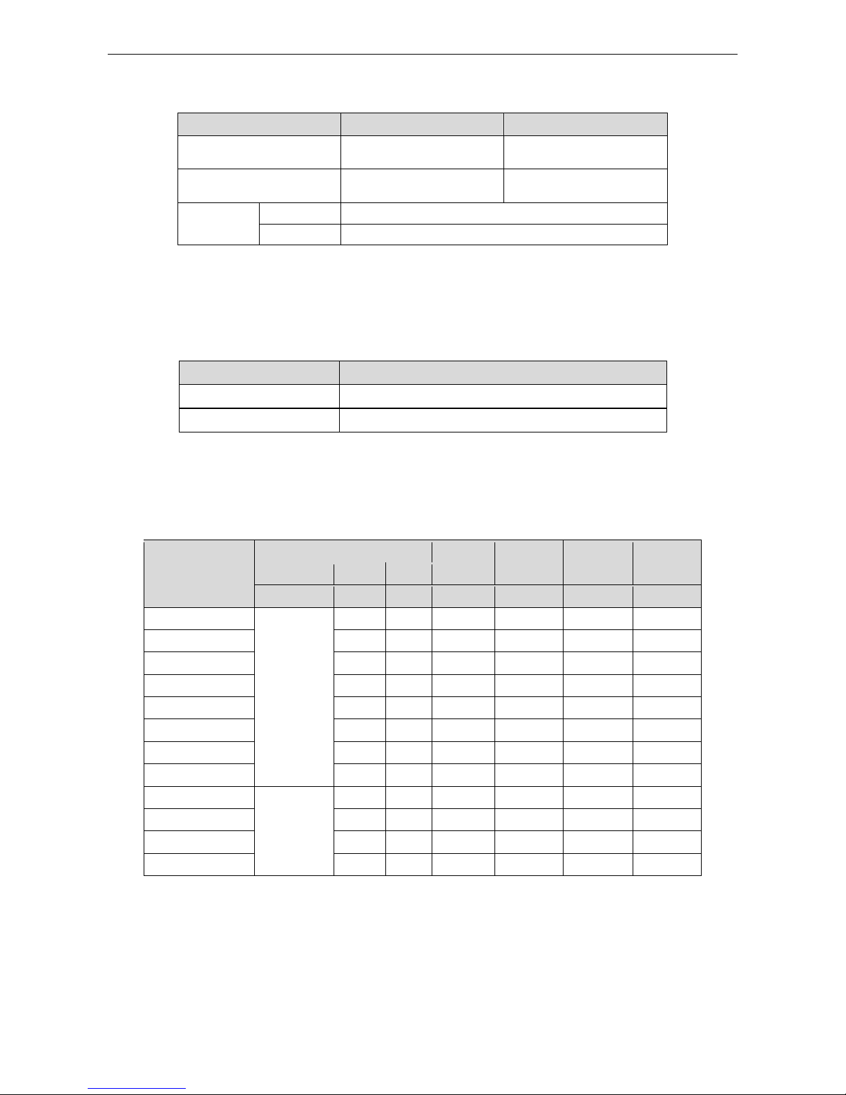
Note: Nominal capacities are based on the follow conditions.
Mode
Indoor
Outdoor
Cooling
DB:27(80.6)
WB:19(66.2)
DB:35(95)
WB:24(75.2)
Heating
DB:20(68)
WB:--(--)
DB:7(44.6)
WB:6(42.8)
Piping
Length
09k-42k
5m
48k-60k
7.5m
The air volume is measured at the relevant standard external static pressure.
Noise is tested in the semianechoic room, so it should be slightly higher in the actual operation due
to environmental change.
3.2 Operation Range
Mode
Range of Outdoor Temperature
Cooling
-15-48
Heating
-10-24
3.3 Electrical Data
3.3.1 Outdoor unit
Table 1-4-1 Electrical Data of Outdoor Unit
Model
Compressor
Fan Motor
Fuse
Capacity
Breaker
Capacity
Min. Power
Supply Cord
Power Supply
Qty.
RLA
FLA
V/Ph/Hz
− A A A A
mm2
GUHD09NK3FO
220-240,1,50
1
4.5
<1
3.15/5
10
1.0
GUHD12NK3FO
1
4.5
<1
3.15/5
10
1.0
GUHD18NK3FO
1
7.2
<1
5/15
16
1.5
GUHD24NK3FO
1
11.5
<1
5/30
20
2.5
GUHD30NK3FO
1
11.5
<1
5/30
20
2.5
GUHD36NK3FO
1
19
<1
5/30
32
4.0
GUHD42NK3FO
1
19
<1
5/30
32
4.0
GUHD48NK3FO
1
21
<1
3.15/5
40
6.0
GUHD36NM3FO
380-415,3,50
1
8
<1
5
16
1.5
GUHD42NM3FO
1
8
<1
5
16
1.5
GUHD48NM3FO
1
8
<1
5
16
1.5
GUHD60NM3FO
1
8
<1
5
16
1.5
U-Match Series DC Inverter Service Manual
15
3.3.2 Indoor unit
Table 1-4-2 Electrical Data of Indoor Unit
Model
Power Supply
Fan Motor FLA
Fuse/Breaker Capacity
Min. Power Supply Cord
V/Ph/Hz A A
mm2
GFH09K3FI
220-240,1,50
<1
5/6
1.0
GTH09K3FI
220-240,1,50
<1
5/6
1.0
GFH12K3FI
220-240,1,50
<1
5/6
1.0
GTH12K3FI
220-240,1,50
<1
5/6
1.0
GKH12K3FI
220-240,1,50
<1
5/6
1.0
GFH18K3FI
220-240,1,50
<1
5/6
1.0
GTH18K3FI
220-240,1,50
<1
5/6
1.0
GKH18K3FI
220-240,1,50
<1
5/6
1.0
GFH24K3FI
220-240,1,50
<1
5/6
1.0
GTH24K3FI
220-240,1,50
<1
5/6
1.0
GKH24K3FI
220-240,1,50
<1
5/6
1.0
GFH30K3FI
220-240,1,50
<1
5/6
1.0
GTH30K3FI
220-240,1,50
<1
5/6
1.0
GKH30K3FI
220-240,1,50
<1
5/6
1.0
GFH36K3FI
220-240,1,50
<1
5/6
1.0
GTH36K3FI
220-240,1,50
<1
5/6
1.0
GKH36K3FI
220-240,1,50
<1
5/6
1.0
GFH42K3FI
220-240,1,50
<1
5/6
1.0
GTH42K3FI
220-240,1,50
<1
5/6
1.0
GKH42K3FI
220-240,1,50
<1
5/6
1.0
GFH48K3FI
220-240,1,50
<1
5/6
1.0
GTH48K3FI
220-240,1,50
<1
5/6
1.0
GFH60K3FI
220-240,1,50
<1
5/6
1.0
GTH60K3FI
220-240,1,50
<1
5/6
1.0
Notes:
RLA: Rated load amperes
LRA: Locked rotor amperes
FLA: Full load current
①
Install the disconnect device with a contact gap of at least 3mm in all poles nearby the units
(Both indoor unit and outdoor unit).The appliance must be positioned so that the plug is
accessible.
②
The specifications of the breaker and power cable listed in the table above are determined based
on the maximum power (maximum amps) of the unit.
③
The specifications of the power cable listed in the table above are applied to the conduit-guarded
multi-wire copper cable (like, YJV copper cable, consisting of PE insulated wires and a PVC
cable jacket) used at 40°С and resistible to 90°С (see IEC 60364-5-52). If the working condition
U-Match Series DC Inverter Service Manual
16
changes, they should be modified according to the related national standard.
④
The specifications of the breaker listed in the table above are applied to the breaker with the
working temperature at 40°С. If the working condition changes, they should be modified
according to the related national standard.
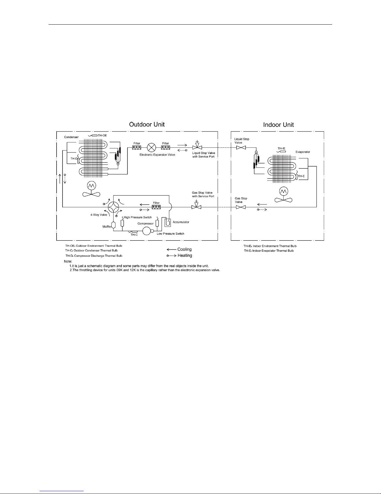
4 PIPING DIAGRAM

U-Match Series DC Inverter Service Manual
17
CONTROL

U-Match Series DC Inverter Service Manual
18
CONTROL
1 OPERATION FLOWCHART
1.1 Cooling/Dry Operation
U-Match Series DC Inverter Service Manual
19
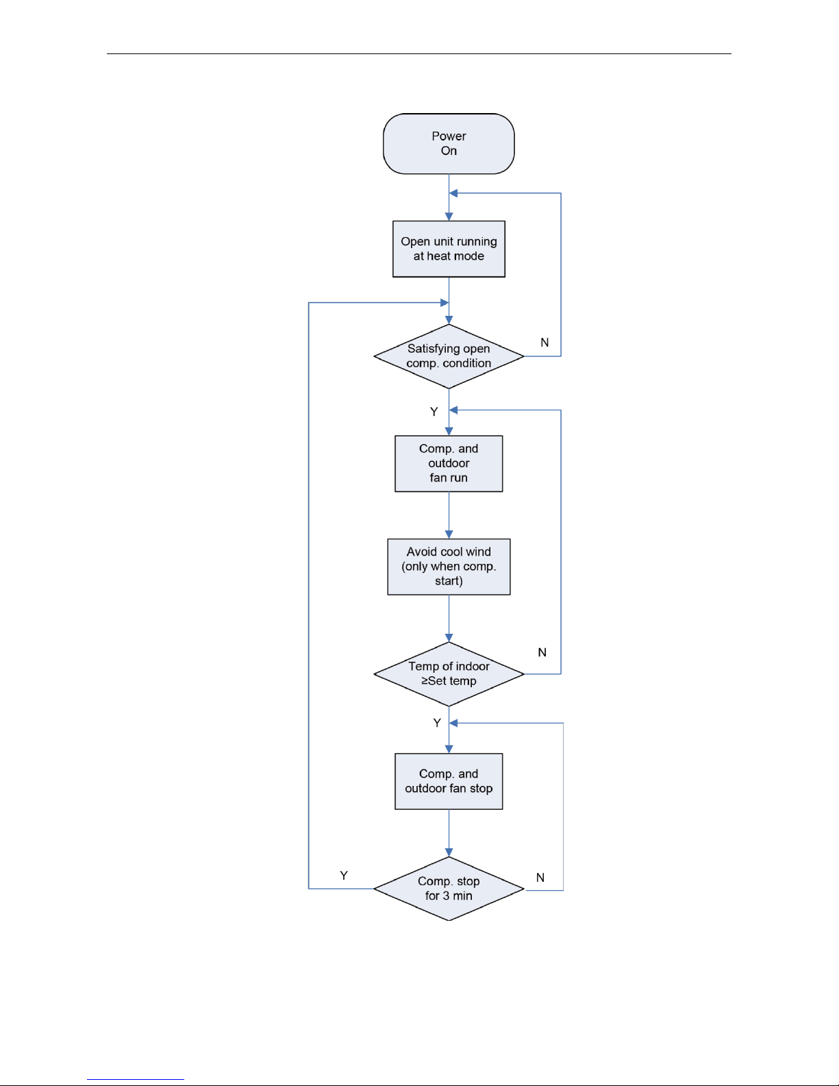
1.2 Heating Operation
U-Match Series DC Inverter Service Manual
20
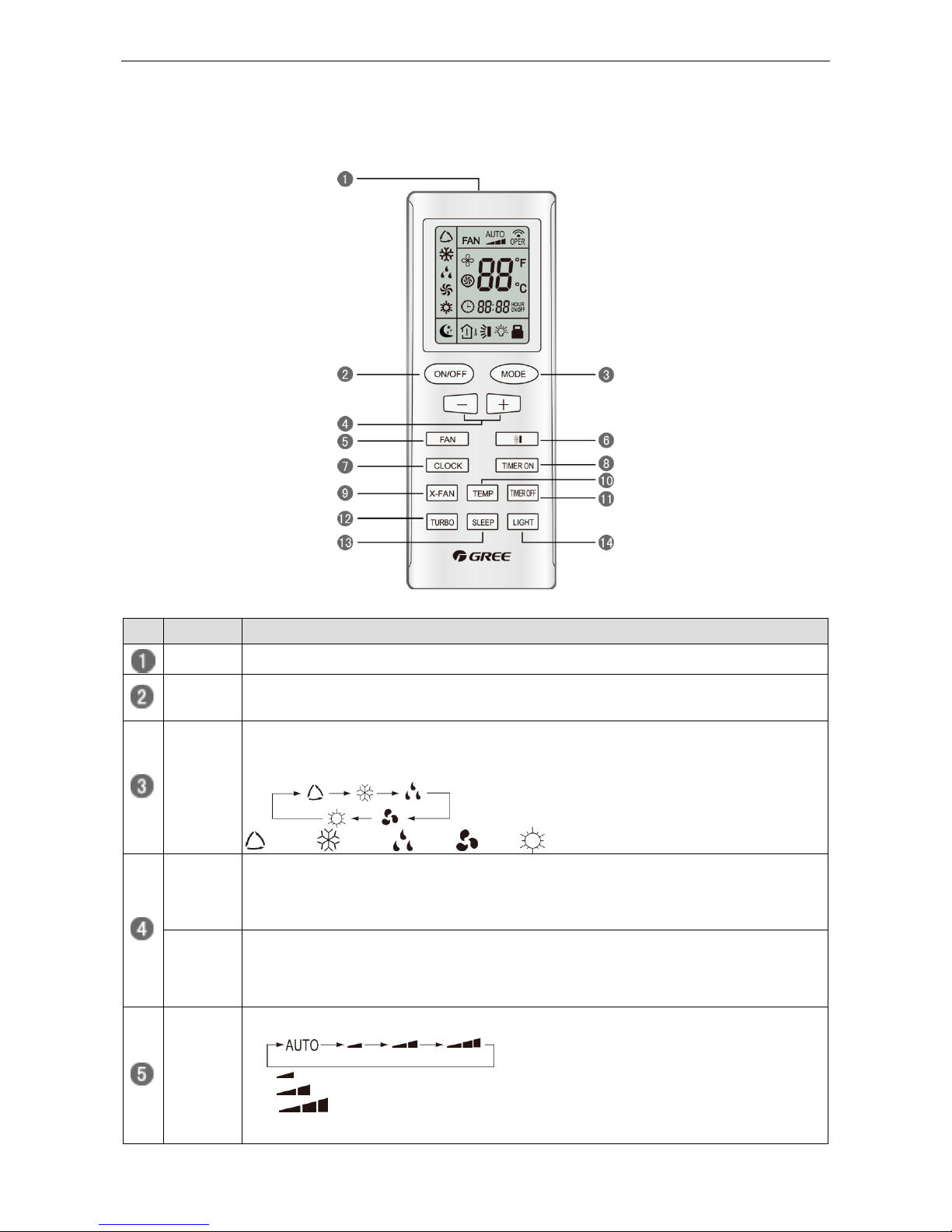
2 WIRELESS REMOTE CONTROLLER
2.1 Operation and Display View
Table 2-2-1 Operation instruction of wireless remote controller
No.
Name
Function Description
Signal
transmitter
Signal transmitter
ON/OFF
button
Press this button and the unit will be turned on; press it once more and the unit will be turned off.
When turning off the unit, the Sleep function will be canceled, but the presetting time is still
remained.
MODE
button
By pressing this button, Auto, Cool, Dry, Fan, Heat mode can be selected circularly. Auto
mode is default after power on. Under the Auto mode, the setting temperature will not be
displayed; Under the Heat mode, the initial value is 28°C (82°F); under other modes, the initial
value is 25°C (77°F).
AUTO; COOL; DRY; FAN; HEAT (only for cooling and heating unit)
- button
Preset temperature can be decreased by pressing this button. Pressing and holding this button
for more than 2 seconds can make the temperature changed quickly until release this button and
then transmit this order. The temperature adjustment is unavailable under the Auto mode, but
the order can be sent by pressing this button. Centigrade setting range: 16-30; Fahrenheit scale
setting range 61-86.
+ button
Preset temperature can be increased by pressing this button. Pressing and holding this button
for more than 2 seconds can make the temperature changed quickly until release the button and
then transmit this order. The temperature adjustment is unavailable under the Auto mode, but
the order can be sent by pressing this button. Centigrade setting range: 16-30; Fahrenheit scale
setting range 61-86.
FAN
button
By pressing this button, Auto, Low, Middle, High speed can be circularly selected. After power
on, Auto fan speed is default.
Low speed
Middle speed
High speed
Note: Under the DRY mode, the fan will be kept running at the low speed and the fan speed isn't
adjustable.
U-Match Series DC Inverter Service Manual
21
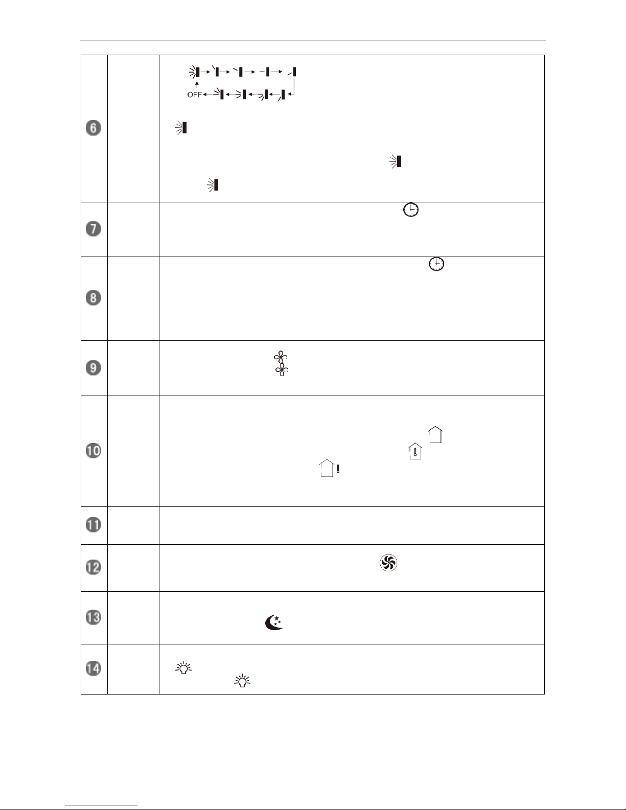
SWING
UP/DOW
N button
Press this button to set up the swing angle, which circularly changes as below:
When the guide louver starts to swing up and down, if SWING functions are canceled, the air
guide louver will stop and remains at the current position.
Indicates the guide louver swings up and down among those five directions.(Simplified
SWING function applicable for some Fan Coil Units: When the wireless remote controller is
energized initially with the unit under the OFF status, it should be set by pressing the + button
and the SWING button simultaneously, with the symbol blinking twice. Then, after the unit is
turned on, this function can be activated by pressing the SWING button, with the displayed
symbol indicating swing function is on and without this displayed symbol indicating swing
function is off.)
CLOCK
button
By pressing this button, the clock is allowed to be set, with blinking, and then press the +/-
button to adjust the clock within 5 seconds. If the +/-button is pressed down constantly for more
than 2 seconds, the clock setting will be increased or decreased 10 minutes every 0.5 seconds.
After that, another press on the CLOCK button accepts the setting. 12:00 is the default, when
the wireless remote controller is energized.
TIMER
ON button
When TIMER ON is activated, ON will blink while the symbol will disappear. Within 5
seconds it is allowed to set the ON time by pressing the +/- button. Each press will make the
time increase or decrease one minute. Besides, the time can also be set by pressing the +/button constantly. That is, in the early 2.5 seconds, the time will increase/decrease quickly per
single minute, and in the late 2.5, the time will increase/decrease per ten minutes. After the
desired time value is set, press TIENE ON again to conform the setting within five seconds. After
that, another press on TIMER ON will cancel the setting. Prior to this setting, the clock shall be
set to the actual time.
X-FAN
button
Pressing this button can activate or deactivate the X-FAN function. In Cool or Dry mode, by
pressing this button, if " " is displayed, it indicates the X-FAN function is activated. By
repressing this button, if " " disappears, it indicates the X-FAN function is deactivated. After
energization, X-FAN OFF is defaulted. If the unit is turned off, X-FAN can be deactivated but
can't be activated.
TEMP
button
By pressing this button it is allowed to select displaying the indoor setting temperature or the
indoor ambient temperature.
Indoor setting temperature is default after the indoor unit is energized initially.
By pressing the TEMP button, when the temperature symbol is displayed, the indoor
displayer will show the indoor setting temperature; when is displayed, it will show the
indoor ambient temperature; when is invalidation, If current displays indoor ambient
temperature, if received the other remote control signal, it will display presetting temperature, 5s
later, will back to display the ambient temperature. (This function is applicable to partial of
models)
TIMER
OFF
button
By pressing this button it is available to go to the TIMER OFF setting state with the same setting
method as that of the TIMER ON, in which case the OFF symbol blinks.
TURBO
button
In the Cool or Heat mode, pressing this button can activate or deactivate the TURBO function.
When the TURBO function is activated, its symbol will be displayed; when the running
mode or the fan speed is changed, this function will be canceled automatically. (This function is
applicable to partial of models).
SLEEP
button
By pressing this button, Sleep On and Sleep Off can be selected. After powered on, Sleep Off is
defaulted. Once the unit is turned off, the Sleep function is canceled. When Sleep is set to on,
the symbol of SLEEP will display. Under the Fan and Auto modes, this function is not
available.
LIGHT
button
Press this button to select LIGHT on or off in the displayer. When the LIGHT is set to on, the icon
will be displayed and the indicating light in the displayer will be on. When the LIGHT is set
to off, the icon will be disappeared and the indicating light in the displayer will be off.
U-Match Series DC Inverter Service Manual
22
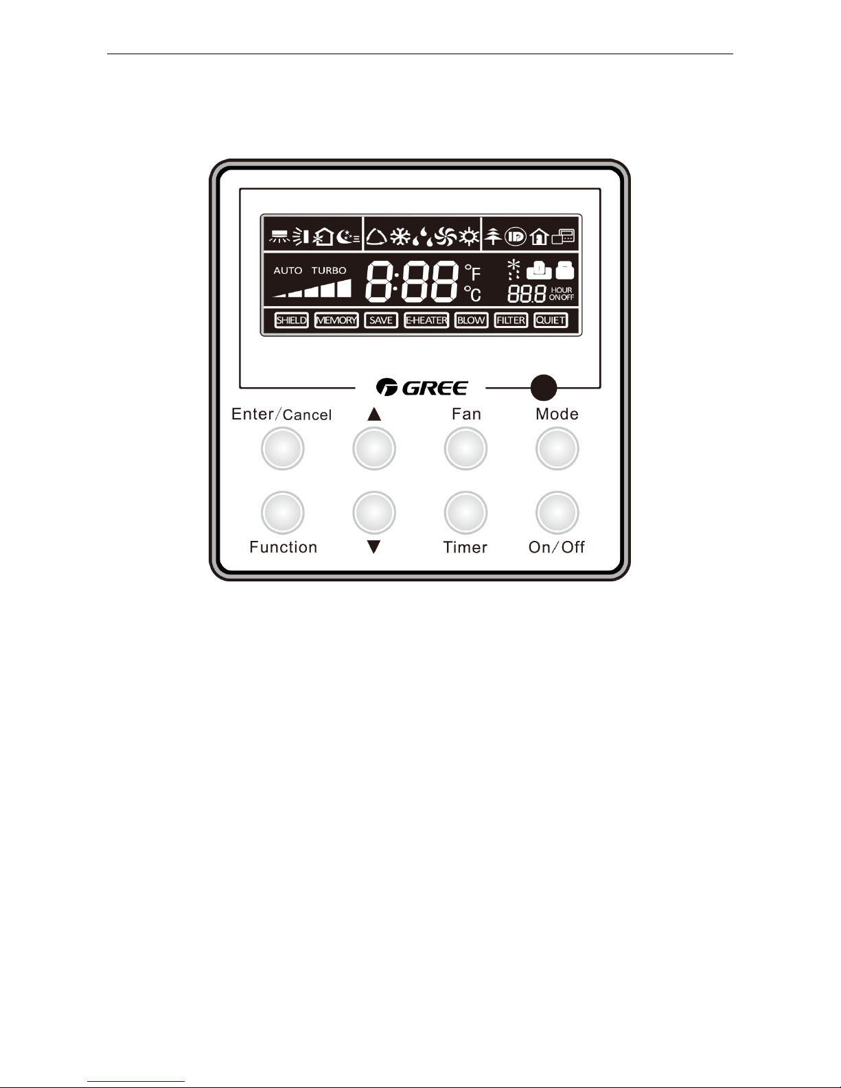
3 WIRED CONTROLLER
3.1 Display View
Figure 2-3-1 Appearance of wired controller
U-Match Series DC Inverter Service Manual
23
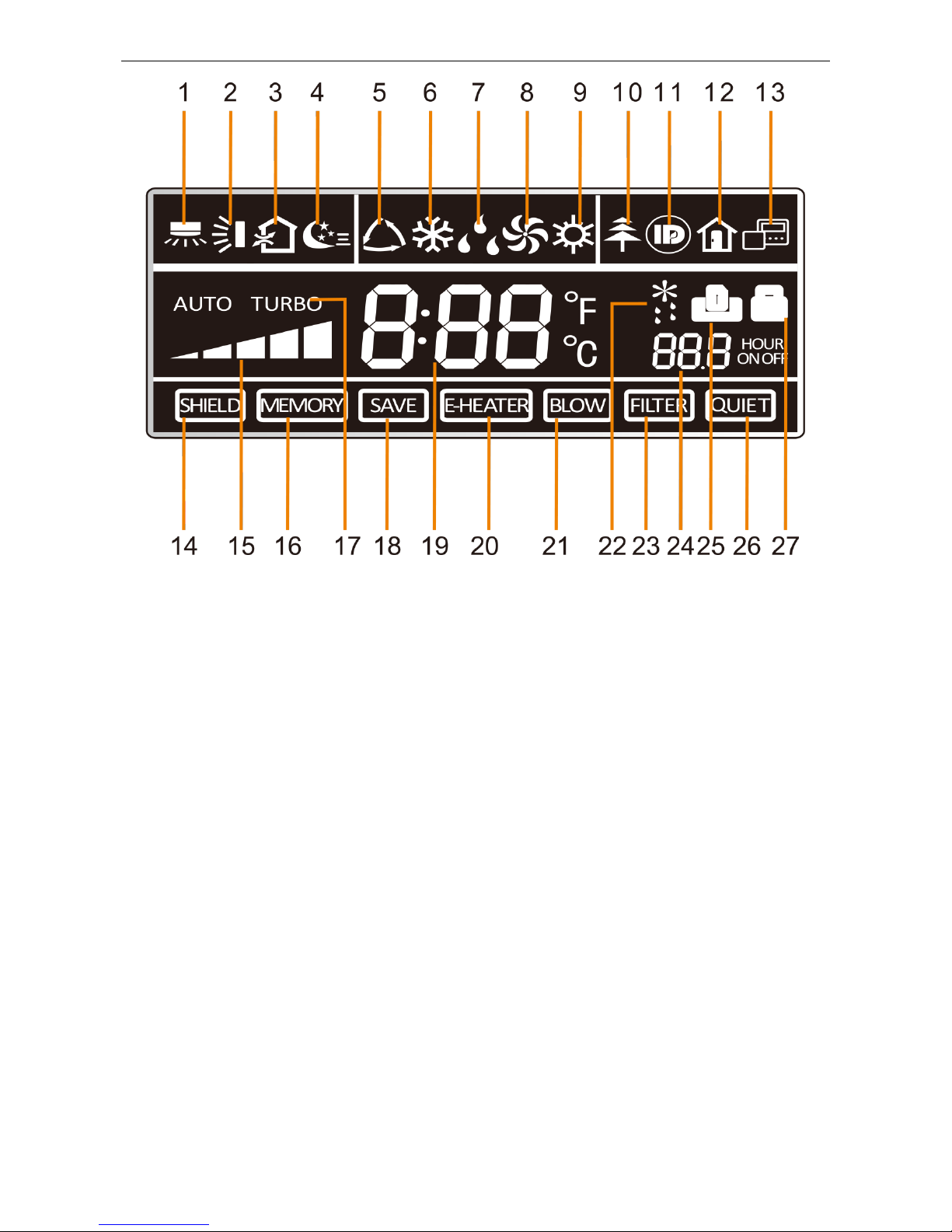
Figure 2-3-2 LCD display of wired controller
U-Match Series DC Inverter Service Manual
24
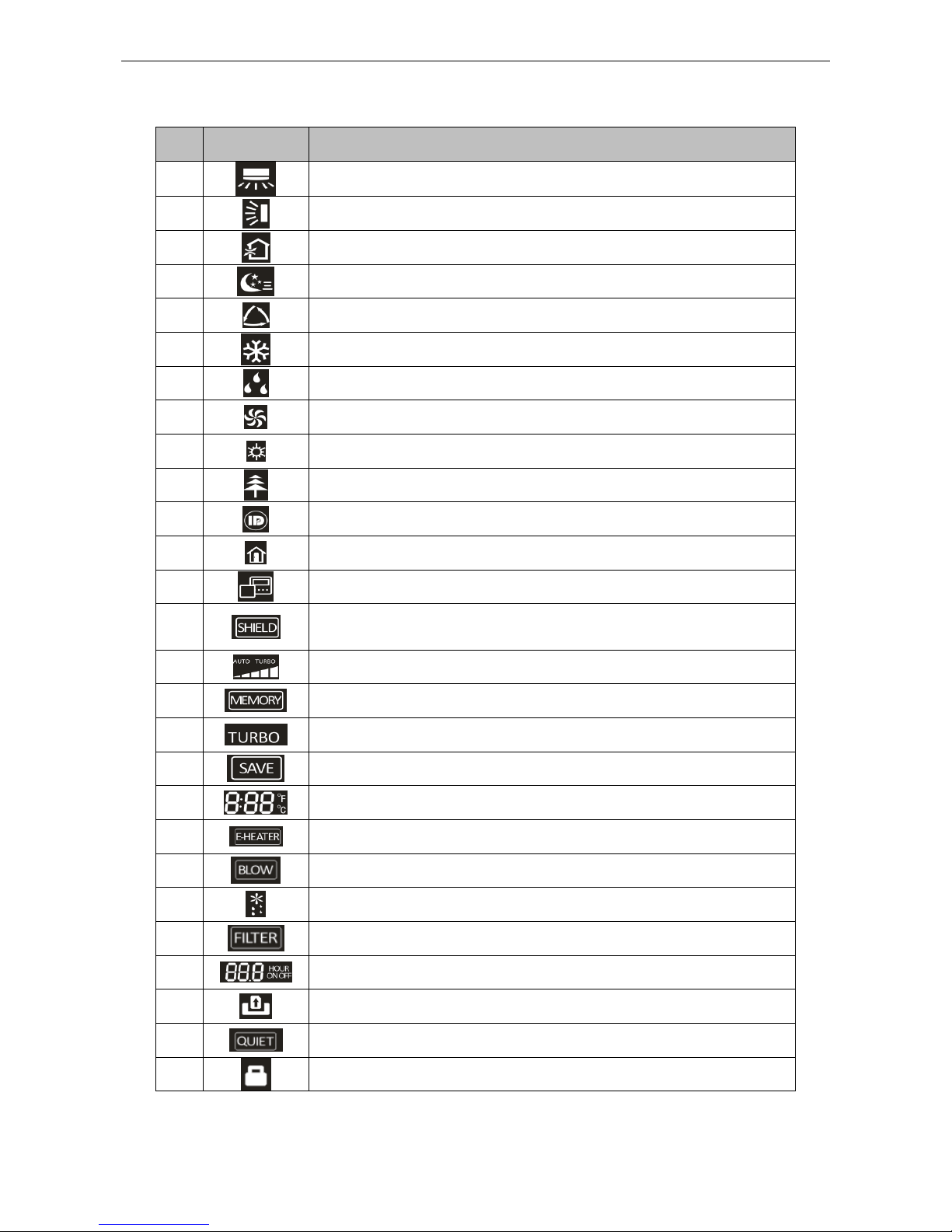
Table 2-3-1 Instruction to LCD Display
No.
Icons
Introduction
1 Left and right swing function
2 Up and down swing function
3 Air exchange function
4 Sleep function
5 Auto mode
6 COOL mode
7 DRY mode
8 FAN mode
9 HEAT mode
10 Health function
11 I-Demand function
12 Vacation function
13 Status display of master and slave wired controller
14
Shield function
The button operation, temperature setting, "On/Off" operation, "Mode" setting,
and "Save" setting are disabled.
15 Fan speed
16
Memory function
The unit will resume the original setting state after power recovery.
17 Turbo function
18 Energy-saving function
19 Ambient/setting temperature
20 Electric heater
21 Blow function
22 Defrosting function
23 Filter cleaning
24 Timer Setting
25 Keycard control / Detected status sensed by human body
26 Quiet function
27 Lock function
U-Match Series DC Inverter Service Manual
25
3.2 Operation View
3.2.1 Silk Screen of Buttons
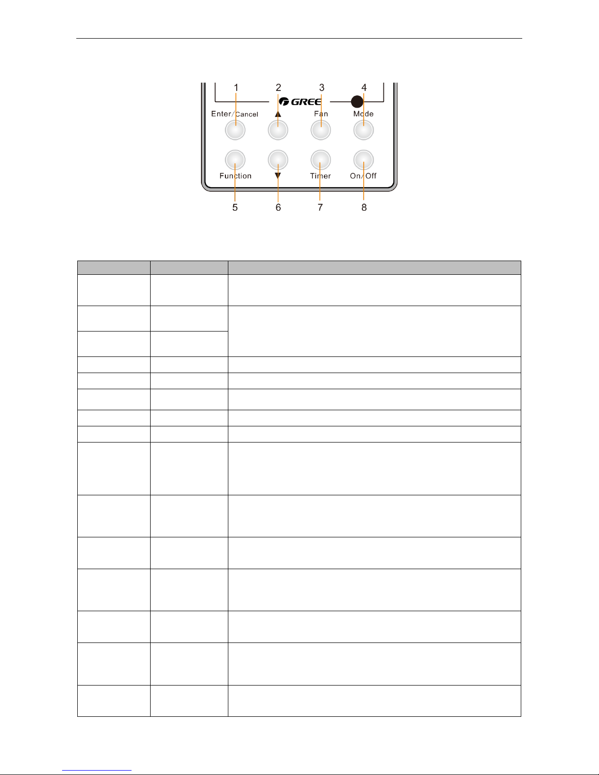
Figure 2-3-3 Silk screen of buttons
3.3.2 Instruction to Function of Buttons
Table 2-3-2 Instruction to buttons of wired controller
No.
Description
Functions
1
Enter/Cancel
(1)Function selection and canceling;
(2)Press it for 5s to view the ambient temperature; press Mode button to
select viewing outdoor ambient temperature or indoor ambient temperature.
2
▲
(1) Running temperature setting range of indoor unit: 16-30℃;
(2) Timer setting range: 0.5-24hr;
(3) Setting of air function level;
(4) Setting of energy-saving temperature;
(5) Setting of cleaning class.
6
▼
3
Fan
Setting of high/medium high/medium/medium low/low/auto fan speed.
4
Mode
Setting of auto/cooling/heating/fan/dry mode of indoor unit.
5
Function
Switch over among these functions of swing/air/sleep/health/
I-Demand/out/turbo/save/e-heater/X-fan/clean/quiet.
7
Timer
Timer setting.
8
On/Off
Turn on/off indoor unit.
4 Mode and
2 ▲
Memory function
Press Mode and ▲ buttons at the same time for 5s under off state of the unit
to enter/cancel memory function (If memory function is set, indoor unit will
resume original setting state after power failure and then power recovery. If
not, indoor unit is defaulted to be off after power recovery. Ex-factory setting
of memory function is on).
2 ▲ and
6 ▼
Lock
Upon startup of the unit without malfunction or under off state of the unit,
press ▲ and ▼ buttons at the same time for 5s to enter lock state. In this
case, any other buttons won‟t respond when pressing. Repress ▲ and ▼
buttons for 5s to quit lock state.
4 Mode and
5 Function
Enquiry and
setting of address
of wired controller
Under off state of the unit, press Mode and Function buttons at the same time
for 5s to set the address. (More details please refer to project debugging)
5 Function and
7 Timer
Setting of project
parameters (More
details please
refer to the Notes)
Under off state of the unit, press Function and Timer buttons at the same time
for 5s to go to the debugging menu. Press Mode button to adjust the setting
items and press ▲ or ▼ buttons to set the actual value.
4 Mode and
6 ▼
Switch between
Fahrenheit and
Centigrade
Under off state of the unit, press Mode and ▼ buttons at the same time for 5s
to switch between Fahrenheit and Centigrade.
5 Function and
6 ▼
Viewing historical
malfunction
Continuously press Function and ▼ buttons for 5s to view historical
malfunction. Then press ▲ and ▼ buttons to adjust displayed contents. The
timer displaying position displays the sequence of malfunction and the
detailed error code. The 5th displayed malfunction is the last malfunction.
1 Enter/Cancel
and
4 Mode
Setting of master
and slave wired
controller
Under off state of the unit, press Enter/Cancel and Mode buttons at the same
time for 5s to set master and slave wired controller. Press ▲ or ▼ button to
adjust. (More details please refer to project debugging)
U-Match Series DC Inverter Service Manual
26
Notes:
The following functions can be set through Function and Timer buttons: setting of ambient
temperature sensor, selecting three speeds in high speed and three speeds in low speed of indoor fan
motor, display setting of freeze protection error code, setting of cold air prevention and hot air hot
prevention function, setting of refrigerant-lacking protection function, selecting of blowing residual heat of
indoor unit, selecting of compressor electric heater mode, selecting of low-power consumption mode,
selecting door control function, selecting human sensitive function, long-distance monitoring,
temperature compensation value at the air return port.
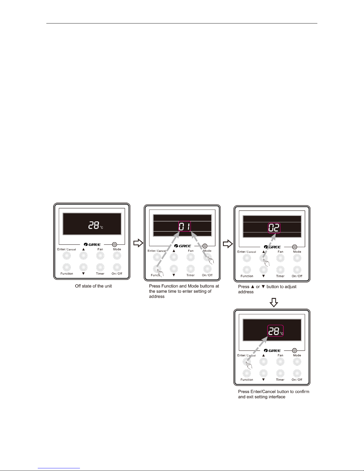
3.2.3 Setting of Wired Controller’s Address
3.2.3.1 Enquiry and Setting of Wired Controller’s Address
Under off state of the unit, press Function and Mode buttons at the same time for 5s to enter setting
interface of wired controller‟s address. In this case, LCD displays address number. Then press▲ or ▼
button to adjust address and then press Enter/Cancel button to confirm. The address setting is related to
the setting of Debugging Function 4.9.10. When the selection in 4.9.10 is 00, address of centralized
controller is to be set and the address setting range is 01~16; when the selection in 4.9.10 is 01, address
of long-distance monitor is to be set and the address setting range is 01~255.
Enquiry and setting of wired controller‟s address is shown as Figure 2-3-4 below:
Figure 2-3-4 Enquiry and setting of wired controller‟s address
U-Match Series DC Inverter Service Manual
27
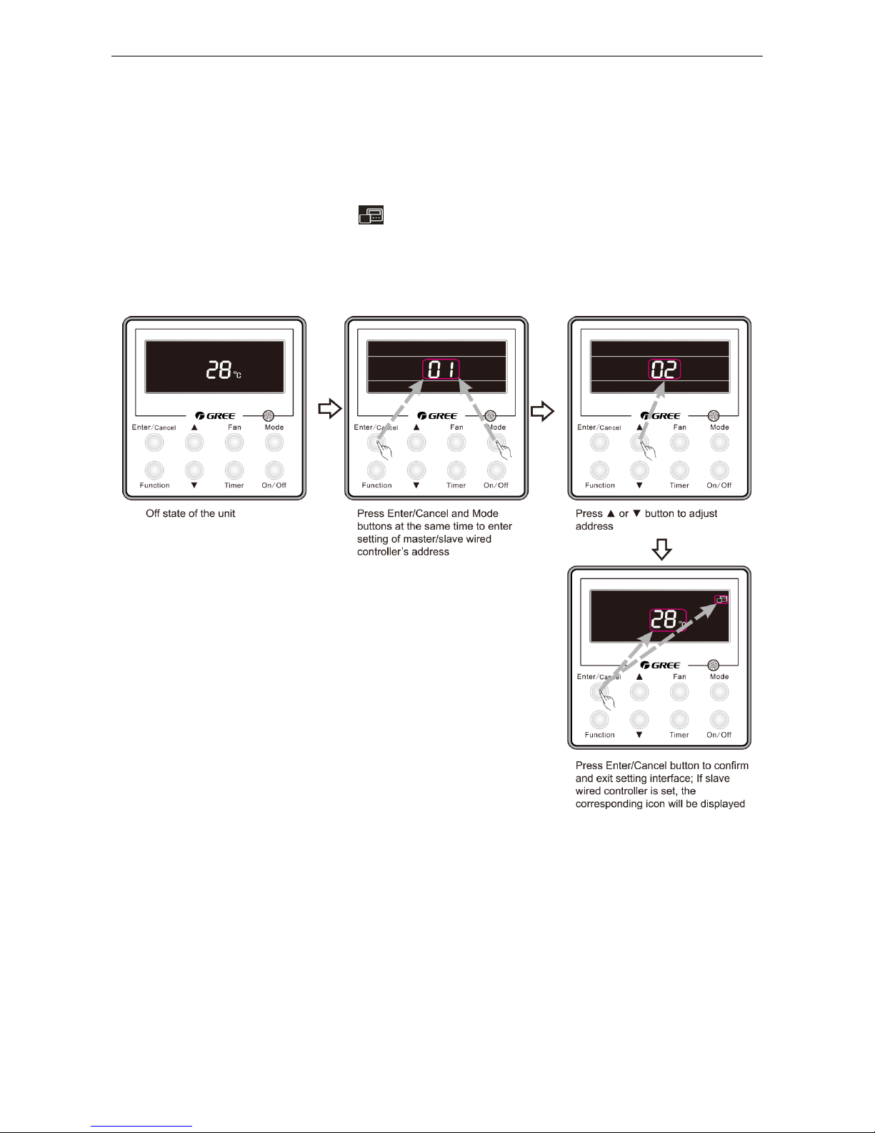
3.2.3.2 Setting of Master/Slave Wired Controller’s Address
Under off status of the unit, press Enter/Cancel and Mode buttons at the same time for 5s to go to
the enquiry and setting interface of master/slave wired controller. In this case, LCD displays wired
controller‟s address (01 for master wired controller and 02 for slave wired controller). Press ▲ or ▼
button to adjust address of master/slave wired controller and then press Enter/Cancel button to confirm.
If slave wired controller is set, the icon will be displayed.
Note: If there is only one wired controller, it only can be set as the master; if there are two wired
controllers, one should be the master and the other should be the slave.
Setting of master/slave wired controller‟s address is shown as Figure 2-3-5 below:
Figure 2-3-5 Enquiry and setting of master/slave wired controller‟s address
 Loading...