

GREE GUHD18NK3FO, GUHD12NK3FO, GUHD09NK3FO, GTH18K3FI, GTH24K3FI Installation Manual
...
Change for life
Air Conditioners
Installation Manual
DC Inverter U-match Series
Floor Ceiling Type Unit
Models:
Indoor Unit Outdoor Unit
GTH09K3FI GUHD09NK3FO
GTH12K3FI GUHD12NK3FO
GTH18K3FI GUHD18NK3FO
GTH24K3FI GUHD24NK3FO
GTH30K3FI GUHD30NK3FO
GTH36K3FI GUHD36NK3FO
GTH42K3FI GUHD42NK3FO
GTH48K3FI GUHD48NK3FO
GTH36K3FI GUHD36NM3FO
GTH42K3FI GUHD42NM3FO
GTH48K3FI GUHD48NM3FO
GTH60K3FI GUHD60NM3FO
Thank you for choosing our product.
For proper operation, please read and keep this manual carefully.
If you have lost the Owner’s Manual, please contact the local
agent or visit www.gree.com or sent email to global@gree.com.cn or electronic version.
GREE reserves the right to interpret this manual which will be subject to any change due
to product improvement without further notice.
GREE Electric Appliances, Inc. of Zhuhai reserves the nal right to interpret this manual.

1 Safety Precautions .......................................................................................... 1
2 Outline of the Unit and Main Parts................................................................... 2
3 Preparative for Installation ............................................................................... 3
3.1 Standard Accessory Parts .......................................................................... 3
3.2 Selection of the Installation Location .......................................................... 4
3.3 Connection Pipe Requirement ................................................................... 5
3.4 Electrical Requirement ............................................................................... 6
4 Installation of the Unit ...................................................................................... 8
4.1 Installation of the Indoor Unit ...................................................................... 8
4.2 Installation of the Outdoor Unit ................................................................. 10
4.3 Installation of the Connection Pipe ........................................................... 12
4.4 Vacuum and Gas Leakage Inspection ......................................................15
4.5 Installation of the Drain Pipe .................................................................... 17
4.6 Electrical Wiring ........................................................................................ 19
5 Installation of Controllers ............................................................................... 24
6 Test Running .................................................................................................. 24
6.1 Trial Operation and Testing ....................................................................... 24
6.2 Working Temperature Range ....................................................................26
7. Troubleshooting and Maintenance ............................................................... 27
7.1 Troubleshooting ........................................................................................ 27
7.2 Routine Maintenance ............................................................................... 28
Contents
DC Inverter U-match Series Floor Ceiling Type Unit
1
1 Safety Precautions
WARNING!
This mark indicates procedures which, if improperly performed, might lead to the
death or serious injury of the user.
CAUTION!
This mark indicates procedures which, if improperly performed, might possibly result
in personal harm to the user, or damage to property.
WARNING!
(1). For operating the air conditioner pleasantly, install it as outlined in this installation manual.
(2). Connect the indoor unit and outdoor unit with the room air conditioner piping and cord available from
our standard parts. This installation manual describes the correct connections using the installation
set available from our standard parts.
(3). Installation work must be performed in accordance with national wiring standards by authorized
personnel only.
(4). If refrigerant leaks while work is being carried out, ventilate the area. If the refrigerant comes in
contact with a ame, it produces toxic gas.
(5). Do not power on until all installation work is complete.
(6). During installation, make sure that the refrigerant pipe is attached firmly before you run the
compressor.
Do not operate the compressor under the condition of refrigerant piping not attached properly with
2-way or 3-way valve open.
This may cause abnormal pressure in the refrigeration cycle that leads to breakage and even injury.
(7). During the pump-down operation, make sure that the compressor is turned off before you remove
the refrigerant piping.
Do not remove the connection pipe while the compressor is in operation with 2-way or 3-way valve
open.
This may cause abnormal pressure in the refrigerant cycle that leads to breakage and even injury.
(8). When installing and relocating the air conditioner, do not mix gases other than the specified
refrigerant (R410A) to enter the refrigerant cycle.
If air or other gas enters the refrigerant cycle, the pressure inside the cycle will rise to an abnormally
high value and cause breakage, injury, etc.
(9). This appliance is not intended for use by persons (including children) with reduced physical,
sensory or mental capabilities, or lack of experience and knowledge, unless they have been given
supervision or instruction concerning use of the appliance by a person responsible for their safety.
(10). Children should be supervised to ensure that they do not play with the appliance.
(11). If the supply cord is damaged, it must be replaced by the manufacturer, its service agent or
similarly qualied persons in order to avoid a hazard.
DC Inverter U-match Series Floor Ceiling Type Unit
2
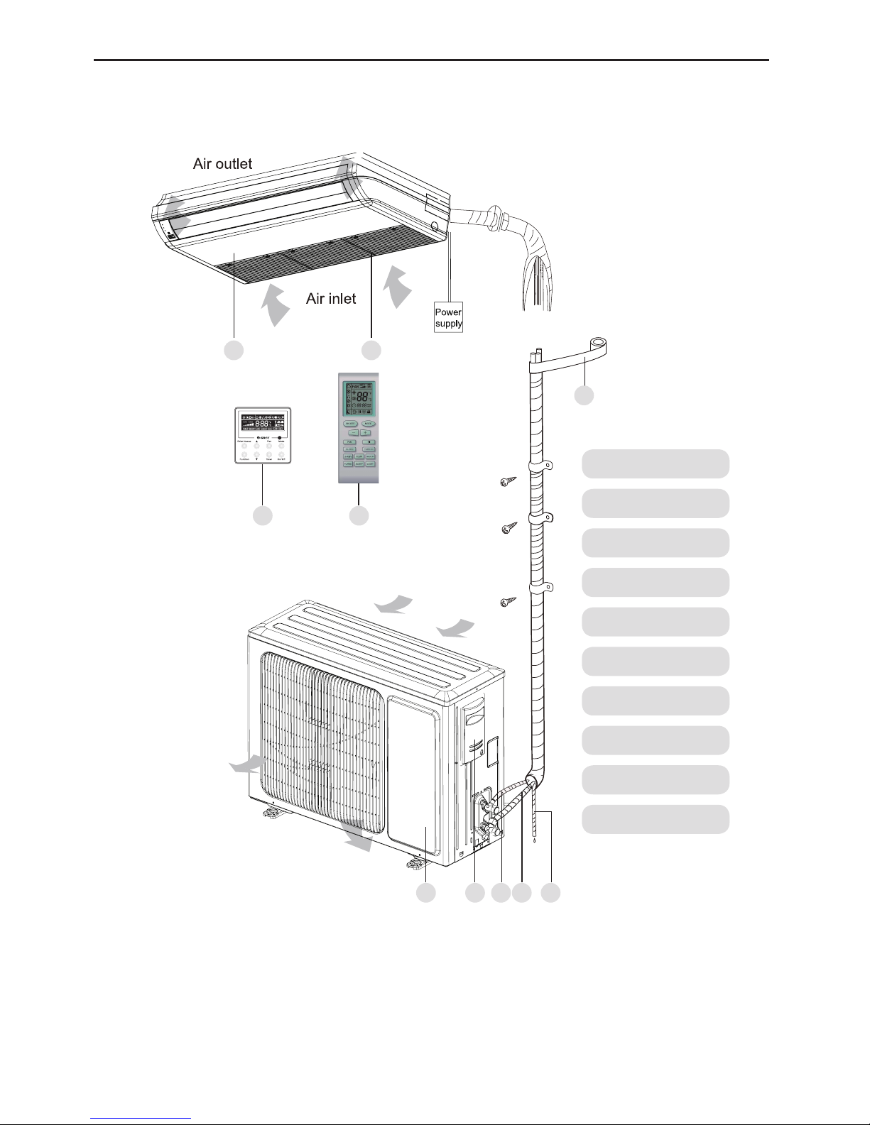
2 Outline of the Unit and Main Parts
Indoor
Outdoor
1. Guide louver
2. Air lter
3. Wired controller
4. Wireless Controller
5. Binding tape
6. Drain Pipe
7. Gas Pipe
8. Lipuid Pipe
9. Big Handle
10. Front Board
3 4
5
679 810
1 2
Air inlet
Air outlet
Fig.1
Notes:
① .
The connection pipe and duct for this unit should be prepared by the user.
② .
This unit is standard equipped with the rectangular duct.
DC Inverter U-match Series Floor Ceiling Type Unit
3
3 Preparative for Installation
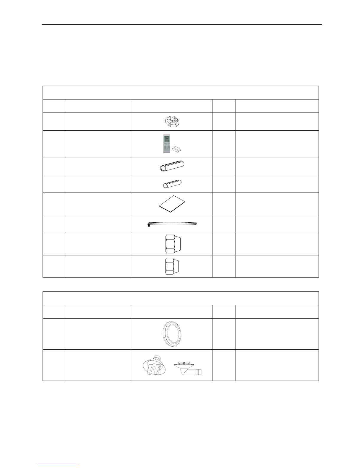
3.1 Standard Accessory Parts
The standard accessory parts listed below are furnished and should be used as required.
Table 1
Indoor Unit Accessories
No. Name Appearance Q'ty Usage
1 Nut with Washer 8
To x the hook on the cabinet
of the unit.
2
Wireless
Controller+Battery
1+2 To control the indoor unit
3 Insulation 1 To insulate the gas pipe
4 Insulation 1 To insulate the liquid pipe
5 Installation Paperboard 2 To insulate the drain pipe
6 Fastener 4 To fasten the sponge
7 Nut
1 To connect gas pipe
8 Nut 1 To connect liquid pipe
Table 2
Outdoor Unit Accessories
No. Name Appearance Q'ty Usage
1 Drain Plug 3 To plug the unused drain hole.
2 Drainage Connecter or 1
To connect with the hard PVC
drain pipe
DC Inverter U-match Series Floor Ceiling Type Unit
4
3.2 Selection of the Installation Location
WARNING!
The unit must be installed where strong enough to withstand the weight of the unit and xed securely,
otherwise the unit would topple or fall off.
CAUTION!
① .
Do not install where there is a danger of combustible gas leakage.
② .
Do not install the unit near heat source, steam, or ammable gas.
③ .
Children under 10 years old must be supervised not to operate the unit.
Decide the installation location with the customer as follows:
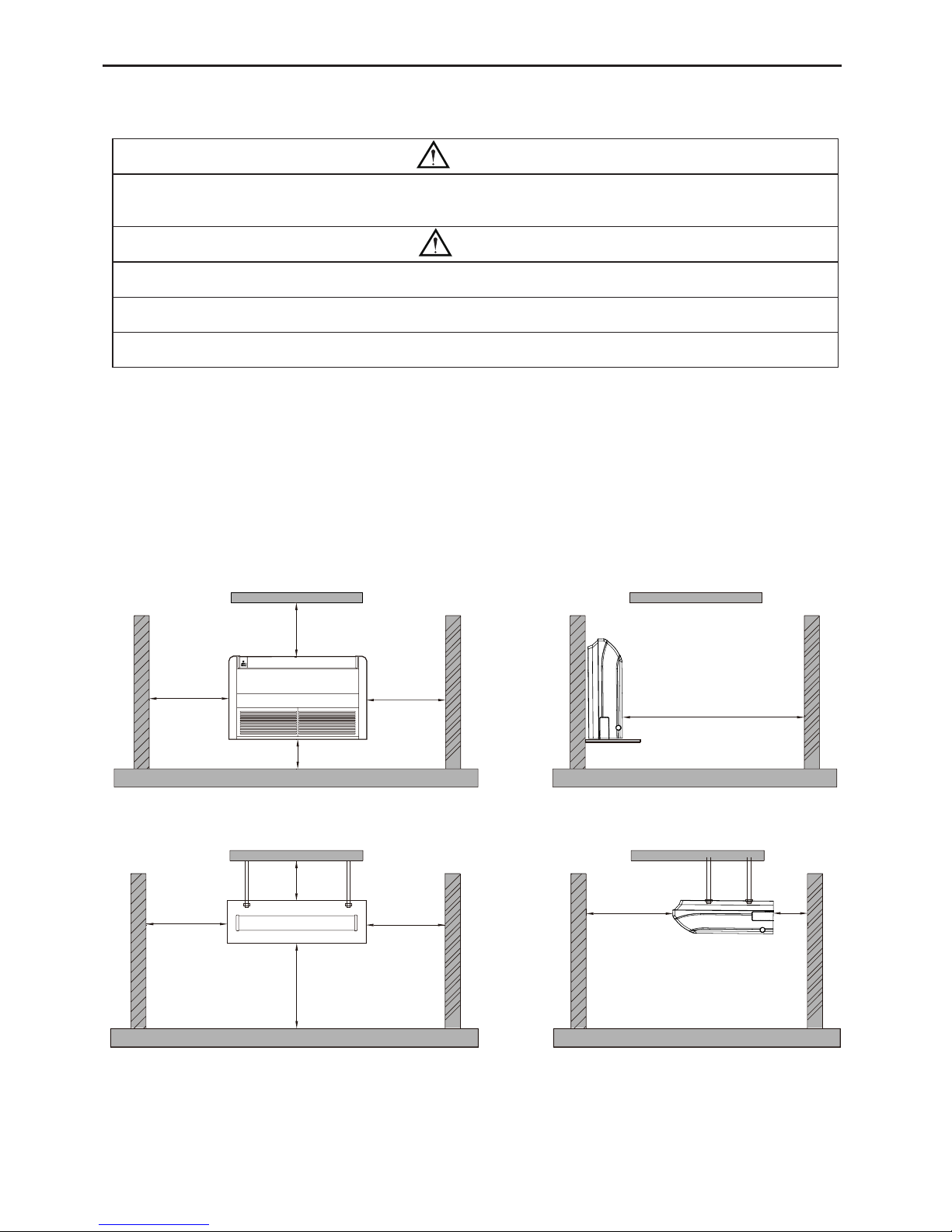
3.2.1 Indoor Unit
(1). Install the unit at a place where is strong enough to withstand the weight of the unit.
(2). The air inlet and outlet of the unit should never be clogged so that the airow can reach
every corner of the room.
(3). Leave service space around the unit as required in Fig.2.
◆
Floor type
Unit: mm
>600
>1000
>300
>600
>1500
◆
Ceiling type
Unit: mm
>300
>600
>600
>1500
>200>2300
Fig. 2
(4). Install the unit where the drain pipe can be easily installed.
(5). The space from the unit to the ceiling should be kept as much as possible so as for more
convenient service.
DC Inverter U-match Series Floor Ceiling Type Unit
5
3.2.2 Outdoor Unit
WARNING!
① .
Install the unit where it will not be tilted by more than 5°.
② .
During installation, if the outdoor unit has to be exposed to strong wind, it must be xed securely.
If possible, do not install the unit where it will be exposed to direct sunlight. (If necessary, install
a blind that does not interfere with the air ow.)
(1). Install the outdoor unit in a place where it will be free from being dirty or getting wet by rain
as much as possible.
(2). Install the outdoor unit where it is convenient to connect with the indoor unit.
(3). Install the outdoor unit where the condensate water can be drained out freely during
heating operation.
(4). Do not place animals and plants in the path of the warm air.
(5). Take the air conditioner weight into account and select a place where noise and vibration
are small.
(6). Install the outdoor unit where is capable of withstanding the weight of the unit and
generates as less noise and vibration as possible.
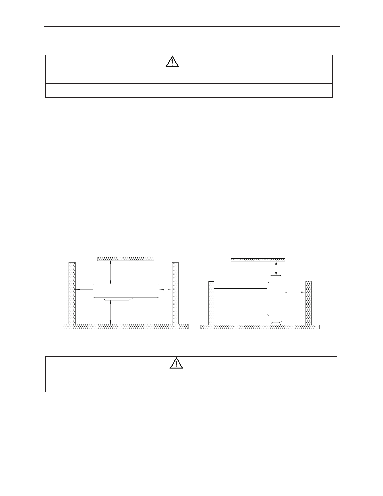
(7). Provide the space shown in Fig.3, so that the air flow is not blocked. Also for efficient
operation, leave three of four directions of peripheral constructions open.
Units: mm
>500
>500 >500
>500
>2000
>2000
>1000
Fig.3
3.3 Connection Pipe Requirement
CAUTION!
The maximum length of the connection pipe is listed in the table below. Do not place the units between
which the distance exceeds the maximum length of the connection pipe.
DC Inverter U-match Series Floor Ceiling Type Unit
6
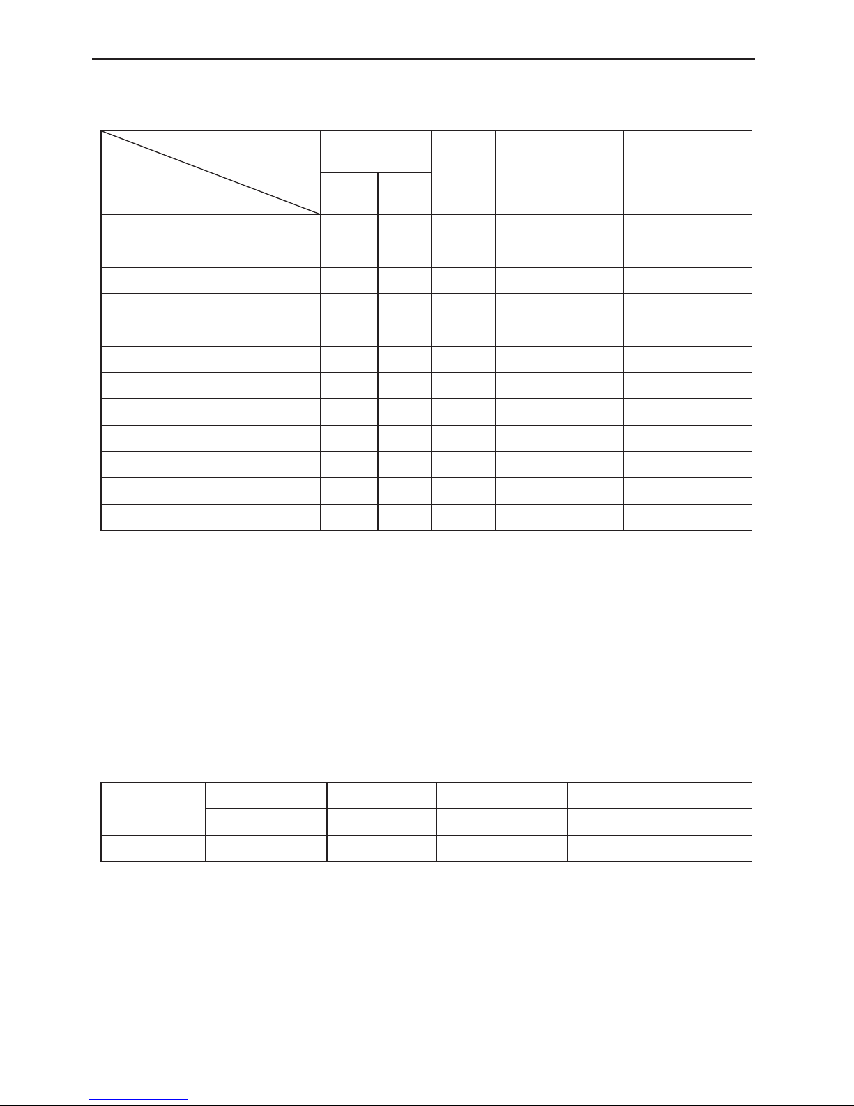
Table 3
Size of Fitting
Pipe(Inch)
Max.
Pipe
Length
(m)
Max. Height
Difference between
Indoor Unit and
Outdoor Unit (m)
Drainage
pipe(Outer
Diameter × wall
thickness) (mm)
Liquid Gas
GTH09K3FI GUHD09NK3FO 1/4 3/8 20 15 φ17×1.75
GTH12K3FI GUHD12NK3FO 1/4 3/8 20 15 φ17×1.75
GTH18K3FI GUHD18NK3FO 1/4 1/2 20 15 φ17×1.75
GTH24K3FI GUHD24NK3FO 3/8 5/8 30 15 φ17×1.75
GTH30K3FI GUHD30NK3FO 3/8 5/8 30 15 φ17×1.75
GTH36K3FI GUHD36NK3FO 3/8 5/8 30 15 φ17×1.75
GTH42K3FI GUHD42NK3FO 3/8 5/8 50 30 φ17×1.75
GTH48K3FI GUHD48NK3FO 3/8 5/8 50 30 φ17×1.75
GTH36K3FI GUHD36NM3FO 3/8 5/8 30 15 φ17×1.75
GTH42K3FI GUHD42NM3FO 3/8 5/8 50 30 φ17×1.75
GTH48K3FI GUHD48NM3FO 3/8 5/8 50 30 φ17×1.75
GTH60K3FI GUHD60NM3FO 3/8 3/4 50 30 φ17×1.75
(1). The connecting pipe should be thermally insulated properly.
(2). The pipe wall thickness shall be 0.5-1.0mm and the pipe wall shall be able to withstand the
pressure of 6.0 MPa. The longer the connecting pipe, the lower the cooling and heating
effect performs.
(3). The pipe wall thickness shall be 0.5-1.0mm and the pipe wall shall be able to withstand the
pressure of 6.0 MPa. The longer the connecting pipe, the lower the cooling and heating
effect performs.
3.4 Electrical Requirement
Electric Wire Size and Fuse Capacity.
Table 4
Indoor Units
Power Supply Fuse Capacity Breaker Capacity Min. Power Supply Cord
V/Ph/Hz A A mm
2
09K~60K 220-240V~ 50Hz 5 6 1.0
Item
Model
DC Inverter U-match Series Floor Ceiling Type Unit
7
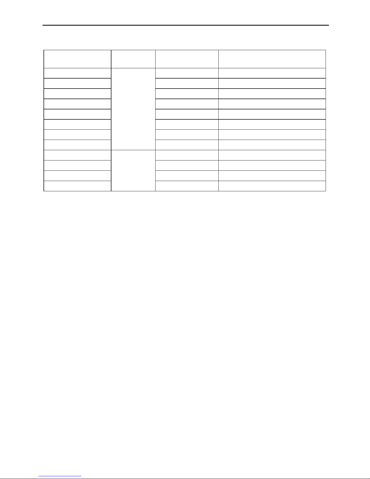
Table 5
Model
Power
Supply
Capability of Air
Switch(A)
Minimum Sectional Area of Power
Cable and Earth line (mm2)
GUHD09NK3FO
220-240V
~
50Hz
13 1.5
GUHD12NK3FO 13 1.5
GUHD18NK3FO 16 1.5
GUHD24NK3FO 20 2.5
GUHD30NK3FO 20 2.5
GUHD36NK3FO 25 2.5
GUHD42NK3FO 25 2.5
GUHD48NK3FO 40 6.0
GUHD36NM3FO
380-415V 3N
~
50Hz
10 1.5
GUHD42NM3FO 10 1.5
GUHD48NM3FO 16 1.5
GUHD60NM3FO 16 1.5
Notes:
① .
The fuse is located on the main board.
② .
Install the disconnect device with a contact gap of at least 3mm in all poles nearby the units
(Both indoor unit and outdoor unit).The appliance must be positioned so that the plug is
accessible.
③ .
The specications of the breaker and power cable listed in the table above are determined
based on the maximum power (maximum amps) of the unit.
④ .
The specifications of the power cable listed in the table above are applied to the conduit-
guarded multi-wire copper cable (like, YJV copper cable, consisting of PE insulated wires and
a PVC cable jacket) used at 40°С and resistible to 90°С(see IEC 60364-5-52). If the working
condition changes, they should be modied according to the related national standard.
⑤ .
The specifications of the breaker listed in the table above are applied to the breaker with
the working temperature at 40°С. If the working condition changes, they should be modied
according to the related national standard.
⑥ .
Take 2 pieces of power cord of 0.75mm2 as the communication lines between indoor and
outdoor unit, with their longest lengths of 50m. Please select the appropriate line length as per
the actual installation conditions. The communication lines can not be twisted together. For
the unit (≤30K), it’s recommended to use 8m long communication line.
⑦ .
Take 2 pieces of power cord of 0.75mm2 as the communication lines between the wired
controller and the indoor unit, with their longest lengths of 30m. Please select the appropriate
line length as per the actual installation conditions. The communication lines can not be twisted
together. It’s recommended to use 8m long communication line.
⑧ .
The wire size of the communication line should be no less than 0.75mm2. It’s recommended to
take 0.75mm2 power cords as the communication line.
DC Inverter U-match Series Floor Ceiling Type Unit
8
4 Installation of the Unit
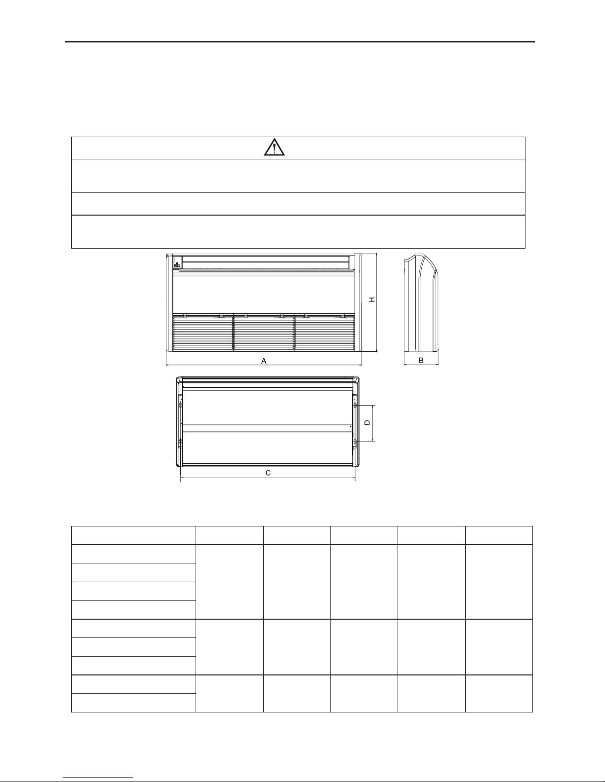
4.1 Installation of the Indoor Unit
4.1.1 Indoor unit dimension
WARNING !
① .
Install the indoor unit in a location which can withstand a load of at least five times the
weight of the main unit and which will not amplify sound or vibration.
② .
If the installation location is not strong enough, the indoor unit may fall and cause injuries.
③ .
If the job is done with the panel frame only, there is a risk that the unit will come loose.
Please take care.
Fig.4
Table 6
Model A B C D H
GTH09K3FI
1220 225 1158 280 700
GTH12K3FI
GTH18K3FI
GTH24K3FI
GTH30K3FI
1420 245 1354 280 700GTH36K3FI
GTH42K3FI
GTH48K3FI
1700 245 1634 280 700
GTH60K3FI
 Loading...