

Gree GUD100W/NhA-T, GUD125W/NhA-T, GUD140W/NhA-T, GUD100W/NhA-X, GUD125W/NhA-X Service Manual
...
1
U-Match 5 SERIES UNIT SERVICE MANUAL
Capacity: 3.5KW~16.0KW
Rate Frequency: 50/60Hz
Operation Range: -20°C ~48℃
Foreword
Thank you for choosing Gree U-Match air conditioners. In order to correctly install and use our units, and for
the satisfactory operation effect, please read this manual carefully.
This manual specifies safe operation requirements from perspectives of product introduction, control,
troubleshooting and maintenance, as well as basic principles and implementation methods. Professional
operators must abide by relevant national (local) safety requirements and technical specifications set forth in this
manual during operations; otherwise, the air conditioning system may fail or be damaged, and personnel safety
accident may also occur.
Safety Notice
The air conditioner is charged with inflammable refrigerant R32.
Before using the air conditioner, please first read the instruction manual.
Before installing the air conditioner, please first read the instruction manual.
Before repairing the air conditioner, please first read the technical service manual.
Compared with common refrigerant, R32 is an environmental-friendly refrigerant that has no harm to the ozone layer and weak
greenhouse effect. Its GWP is 675. Because of its thermodynamic characteristics, R32 requires a smaller charging quantity to reach
high energy efficiency. It is inflammable and odourless, but may cause explosion under certain circumstances.

CONTENTS
1. SAFETY NOTICE ON MAINTENANCE ......................................................................................................... 1
2. SAFETY NOTICE ON OPERATION ............................................................................................................... 2
1. PRODUCT INTRODUCTION ............................................................................................................................ 3
1.1 Lists of Units ..................................................................................................................................................................... 3
1.1.1 List of ODUs ....................................................................................................................................................................... 3
1.1.2 List of IDUs ......................................................................................................................................................................... 4
1.2 Electrical Parameters ........................................................................................................................................................ 8
2. CONTROL ............................................................................................................................................................... 9
2.1 Operation Mode ............................................................................................................................................................... 9
2.1.1 Cooling Mode ..................................................................................................................................................................... 9
2.1.2 Heating Mode ................................................................................................................................................................... 10
2.2 Control Mode ................................................................................................................................................................. 10
2.2.1 Based Control ................................................................................................................................................................... 10
2.2.2 Special Control ................................................................................................................................................................. 11
2.2.3 Protection Control ............................................................................................................................................................ 12
2.3 Functions ....................................................................................................................................................................... 12
2.3.1 Setting of Filter Cleaning Reminder .............................................................................................................................. 12
2.3.2 Low-temperature Drying Function ................................................................................................................................. 13
2.3.3 Child-lock Function .......................................................................................................................................................... 13
2.3.4 Memory Function ............................................................................................................................................................. 13
2.3.5 Door Control Function ..................................................................................................................................................... 13
2.3.6 Switch between Fahrenheit and Degree Celsius ........................................................................................................ 14
2.3.7 Inquiry of Ambient Temperature ..................................................................................................................................... 14
2.3.8 Inquiry of Historical Malfunction ..................................................................................................................................... 14
2.3.9 Debugging Function ........................................................................................................................................................ 14
2.3.10 Connect to Interface of Centralized Control .............................................................................................................. 17
3. TROUBLESHOOTING ......................................................................................................................................19
3.1 Wiring Diagrams ............................................................................................................................................................. 19
3.1.1 Wiring Diagrams of ODUs .............................................................................................................................................. 19
3.1.2 Wiring Diagrams of IDUs ................................................................................................................................................ 23
3.2 PCB Layout ..................................................................................................................................................................... 26
3.2.1 Interface ............................................................................................................................................................................ 26
3.2.2 IPM,PFC Testing Method ................................................................................................................................................ 37
3.3 Error Code ...................................................................................................................................................................... 39

3.4 Troubleshooting ............................................................................................................................................................. 41
3.4.1 ―E1‖ Compressor High Pressure Protection ................................................................................................................ 41
3.4.2 ―E2‖ Indoor Anti-freezing Protection .............................................................................................................................. 42
3.4.3 ―E3‖ Compressor Low-pressure Protection, Refrigerant Shortage Protection, Refrigerant Recovery Mode ..... 43
3.4.4 ―E4‖ Compressor Air Discharge High-temperature Protection .................................................................................. 44
3.4.5 ―E6‖ Communication Error .............................................................................................................................................. 45
3.4.6 ―E8‖ Indoor Fan Error ...................................................................................................................................................... 46
3.4.7 ―E9‖ Water Overflow Protection ..................................................................................................................................... 47
3.4.8 ―F0‖ Indoor Ambient Temperature Sensor Error .......................................................................................................... 48
3.4.9 ―F1‖ Evaporator Temperature Sensor Error ................................................................................................................. 49
3.4.10 ―F2‖ Condenser Temperature Sensor Error ............................................................................................................... 50
3.4.11 ―F3‖ Outdoor Ambient Temperature Sensor Error ..................................................................................................... 51
3.4.12 ―F4‖ Discharge Temperature Sensor Error ................................................................................................................ 52
3.4.13 ―F5‖ Wired Control Temperature Sensor Error .......................................................................................................... 53
3.4.14 ―C5‖ IDU Jumper Cap Error ......................................................................................................................................... 54
3.4.15 ―EE‖ IDU or ODU Memory Chip Error ......................................................................................................................... 54
3.4.16 ―PF‖ Electric Box Sensor Error .................................................................................................................................... 55
3.4.17 ―H3‖ Compressor Overload Protection ....................................................................................................................... 56
3.4.18 ―H4‖ Overload ................................................................................................................................................................. 56
3.4.19 ―H5‖ IPM Protection ....................................................................................................................................................... 57
3.4.20 ―H6‖ DC Fan Error ......................................................................................................................................................... 58
3.4.21 ―H7‖ Driver Out-of-Step Protection .............................................................................................................................. 59
3.4.22 ―HC‖ PFC Protection ..................................................................................................................................................... 60
3.4.24 ―Lp‖ IDU and ODU Unmatched .................................................................................................................................... 62
3.4.25 ―U7‖ 4–Way Valve Switch-Over Error ......................................................................................................................... 63
3.4.26 ―P0‖ Driver Reset Protection ........................................................................................................................................ 63
3.4.27 ―P5‖ Over-Current Protection ....................................................................................................................................... 64
3.4.28 ―P6‖ Master Control and Driver Communication Error ............................................................................................. 65
3.4.29 ―P7‖ Driver Module Sensor Error ................................................................................................................................. 66
3.4.30 ―P8‖ Driver Module High Temperature Protection ..................................................................................................... 67
3.4.31 ―PA‖ AC Current Protection .......................................................................................................................................... 67
3.4.32 ―Pc‖ Driver Current Error .............................................................................................................................................. 68
3.4.33 ―Pd‖ Sensor Connection Protection ............................................................................................................................ 69
3.4.34 ―PL‖ Bus Low-Voltage Protection ................................................................................................................................ 69
3.4.35 ―PH‖ Bus High-Voltage Protection ............................................................................................................................... 70
3.4.37 ―ee‖ Drive Memory Chip Error ...................................................................................................................................... 71
3.4.38 ―c4‖ ODU Jumper Cap Error ........................................................................................................................................ 72
3.4.39 ―EL‖ Emergency Stop (Fire Alarm) .............................................................................................................................. 73
3.5 Failures Not Caused by Errors ......................................................................................................................................... 73
4. MAINTENANCE ..................................................................................................................................................75
4.1 System Diagram .............................................................................................................................................................. 75
4.2 Connection Pipe Vacuum Pumping .................................................................................................................................. 75
4.3 Refrigerant Charging ....................................................................................................................................................... 76

4.4 Maintenance of Major Components ................................................................................................................................ 78
4.5 Removal of Major Components....................................................................................................................................... 78
4.5.1 Removal of ODU Major Components ........................................................................................................................... 78
4.5.2 Removal of IDU Major Components ........................................................................................................................... 114
4.6 Explosive View and Lists of Parts ................................................................................................................................... 125
4.6.1 ODU Explosive View and Lists of Parts ...................................................................................................................... 125
4.6.2 IDU Explosive View and Lists of Parts ........................................................................................................................ 146
APPENDICES ........................................................................................................................................................ 180
1 Resistance/temperature lists of temperature sensors ........................................................................................................ 180
1.1 Voltage list of 15 kΩ temperature sensors (including ODU and IDU temperature sensors) .................................. 180
1.2 Voltage list of 20 kΩ pipeline temperature sensors (including temperature sensors for defroster, IDU and ODU
pipes) ......................................................................................................................................................................................... 182
1.3 Voltage list of 50 kΩ discharge temperature sensors (including discharge air temperature sensor) ................... 185
2. Temperature/Pressure List of Refrigerant ......................................................................................................................... 187
3. Refrigerant Notice/Concentration ....................................................................................................................................188
4. Operation Tools ............................................................................................................................................................... 189

GREE U-Match 5 SERIES UNIT SERVICE MANUAL
1
1. Safety Notice on Maintenance
PROHIBITED:
1. Do not pierce or burn.
2. Please note that refrigerant may be odorless.
3. The appliance shall be stored in a room without continuously operating ignition sources (For example: open
flames, an operating gas appliance or an operating electric heater).
4. Indoor unit adopts special joints that can’t be detached. The installation method is the same with the
common joints. However, because the joint can’t be detached, if it is badly connected and causes leakage,
it needs to be cut and replaced by a new one through welding.
5. Using unsuitable parts or tools may lead to electric shock or fire hazard.
6. If refrigerant leaks during maintenance, please ventilate the room immediately. Heavy leakage may lead to
breathing difficulty, severe injury or death.
7. Disconnect power before disassembling the appliance for maintenance.
8. The appliance should be maintained and cared by authorized technical personnel with necessary
qualifications.
WARNING:
1. If the working place is more than 2m's high, please wear a safety helmet, gloves and a safety belt.
2. Never mix any other substances except the specified refrigerant into the refrigerant circuit.
3. When re-locating the appliance, check whether the new location is strong enough to withstand the weight of
the appliance.
4. If there is refrigerant leak, please fix the leak before charging in the refrigerant. After refrigerant is charged,
check for refrigerant leaks. If you cannot spot the leak, stop the maintenance work. Please evacuate the
system and close the service valve to prevent refrigerant leaking into the room.
5. Prepare suitable tools and protectors.
6. If you need to carry out maintenance or check the electric circuit without cutting off the power, please be
careful not to touch the electrical parts.
NOTICE:
1. If the appliance is maintained at a humid place, it should be grounded to avoid electric shock.
2. Never repair the unit with wet hands. Operating the unit with wet hands may lead to electric shock.
3. If the unit is not correctly grounded, please check and fix it.
4. Before cleaning the unit, please disconnect power to prevent the inner fan from starting up and running at
high speed; otherwise personal injury may occur.
5. Measure the insulation resistance after maintenance. The resistance must be 1M or higher. Bad insulation
may lead to electric shock.
6. Welding and cutting work must be done in a well-ventilated place.
7. Gas appliances, heaters and other fire sources should be kept away from the installation and maintenance
site.
8. Maintenance should be done according to suggestions of the manufacturer.
9. Maintenance should be done only after the refrigerant is completely reclaimed from the unit.
GREE U-Match 5 SERIES UNIT SERVICE MANUAL
2
OBSERVED:
1. After the maintenance work is done, check the drainage of indoor unit.
2. Do not tilt the unit, otherwise, water may spill out from the unit and make the floor and furniture wet.
3. Disassembly of the unit, handling of the refrigerant, oil and accessories should all be done according to
applicable local rules and regulations.
2. Safety Notice on Operation
PROHIBITED:
1. Never try to modify the unit, otherwise, it may cause electric shock, overheat or fire hazard.
2. If the power cord or conducting wires are scratched, please replace them.
3. Never use connected or extended power cord or share the power socket with other appliances.
4. Prepare a specialized power circuit for the appliance.
WARNING:
1. If the power plug is dirty, please clean it before inserting it to the power socket. If the power plug is loose,
please tighten it up.
2. Do not damage the power cord. A damaged or refitted power cord may lead to electric shock or fire hazard.
3. Check frequently whether the appliance is in good condition.
NOTICE:
1. After changing the batteries of remote control, please discard them to avoid being swallowed by children.
2. When the unit is working, do not remove the fan cover.
3. Do not use organic solvents to wipe the controller operating panel.
4. Before cleaning the unit, cut off the power supply.
GREE U-Match 5 SERIES UNIT SERVICE MANUAL
3
1. Product Introduction
1.1 Lists of Units
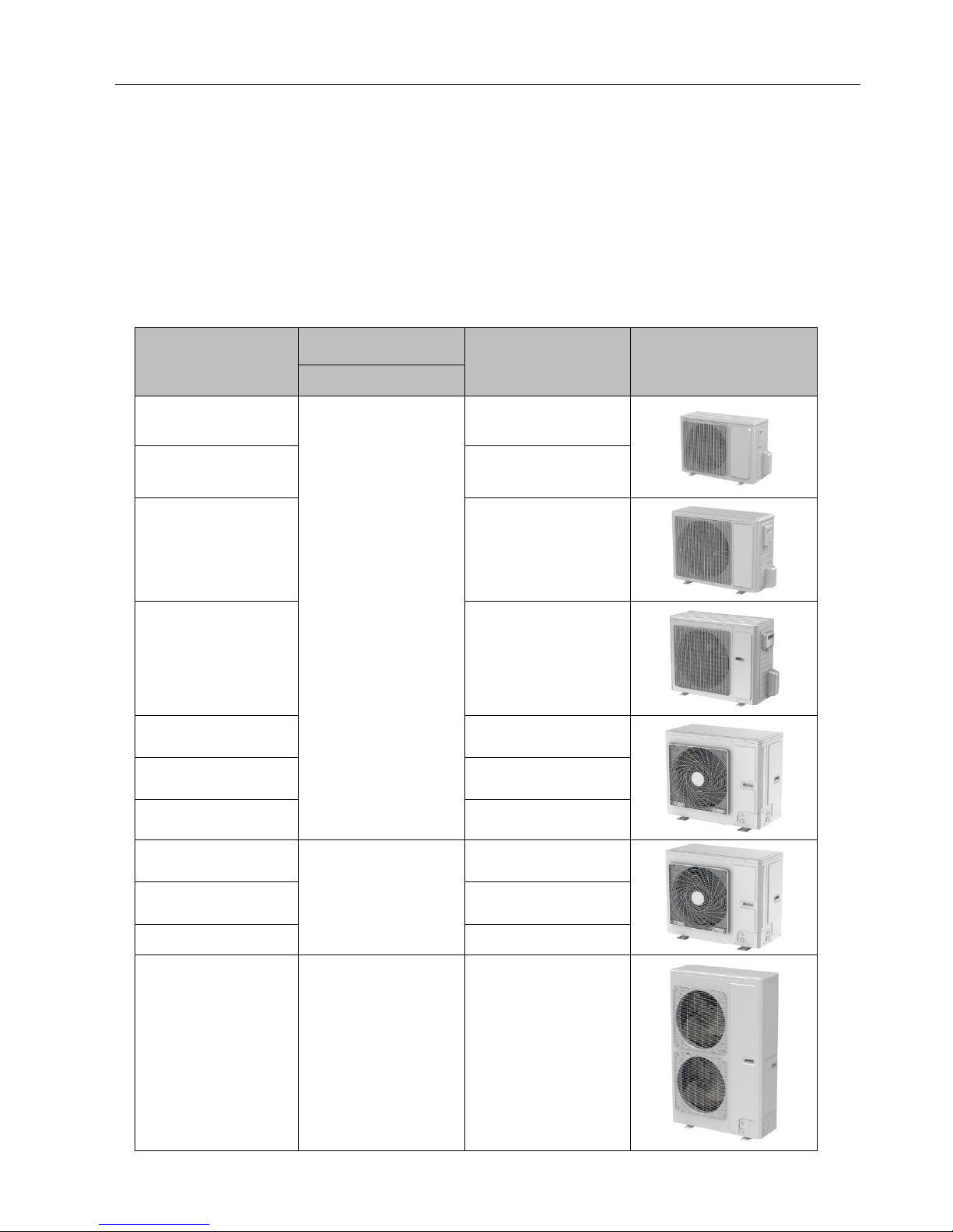
1.1.1 List of ODUs
Model
Power Supply
Finished Product Code
Appearance
V/Ph/Hz
GUD35W/NhA-T
220-240V 1N~50Hz
208-230V 1N~60Hz
CF090W1310
GUD50W/NhA-T
CF090W1210
GUD71W/NhA-T
CF090W1220
GUD85W/NhA-T
CF090W1230
GUD100W/NhA-T
CF090W1240
GUD125W/NhA-T
CF090W1260
GUD140W/NhA-T
CF090W1280
GUD100W/NhA-X
380-415V 3N~50Hz/60Hz
CF090W1250
GUD125W/NhA-X
CF090W1270
GUD140W/NhA-X
CF090W1290
GUD160W/NhA-X
380-415V 3N~50Hz/60Hz
CF090W1300
GREE U-Match 5 SERIES UNIT SERVICE MANUAL
4
Note: 1 Ton =12000Btu/h = 3.517kW
If one outdoor unit is to be connected with multiple indoor units, the indoor units must have the same cooling capacity and be of the
same type.
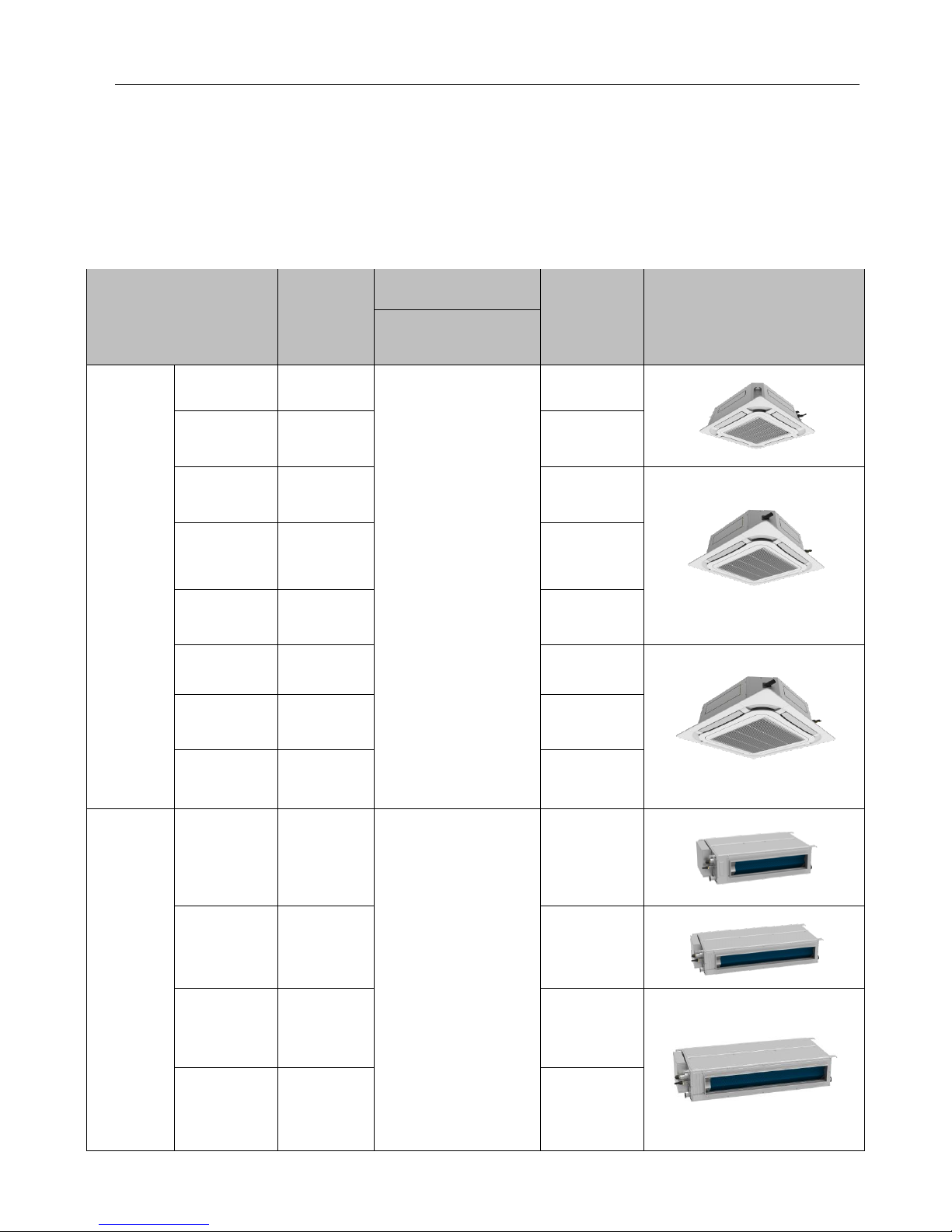
1.1.2 List of IDUs
Model
Rated
Cooling/
Hating
Capacity (kw)
Power Supply
Finished
Product Code
Appearance
V/Ph/Hz
Cassette
Type
GUD35T/A-T
-
220-240V 1N~50Hz
208-230V 1N~60Hz
-
GUD50T/A-T
5.0/5.5
ET010N1540
GUD71T/A-T
7.0/8.0
ET010N1420
GUD85T/A-T
8.5/8.8
ET010N1430
GUD100T/A-T
10.0/12.0
ET010N1440
GUD125T/A-T
12.1/13.5
ET010N1450
GUD140T/A-T
13.4/15.5
ET010N1460
GUD160T/A-T
14.5/17.0
ET010N1470
Duct Type
GUD35P/A-T
3.5/4.0
220-240V 1N~50Hz
208-230V 1N~60Hz
CF022N1650
GUD50P/A-T
5.0/5.5
CF022N1630
GUD71P/A-T
7.0/8.0
CF022N1620
GUD85P/A-T
8.5/8.8
CF022N1610

GREE U-Match 5 SERIES UNIT SERVICE MANUAL
5
Model
Rated
Cooling/
Hating
Capacity (kw)
Power Supply
Finished
Product Code
Appearance
V/Ph/Hz
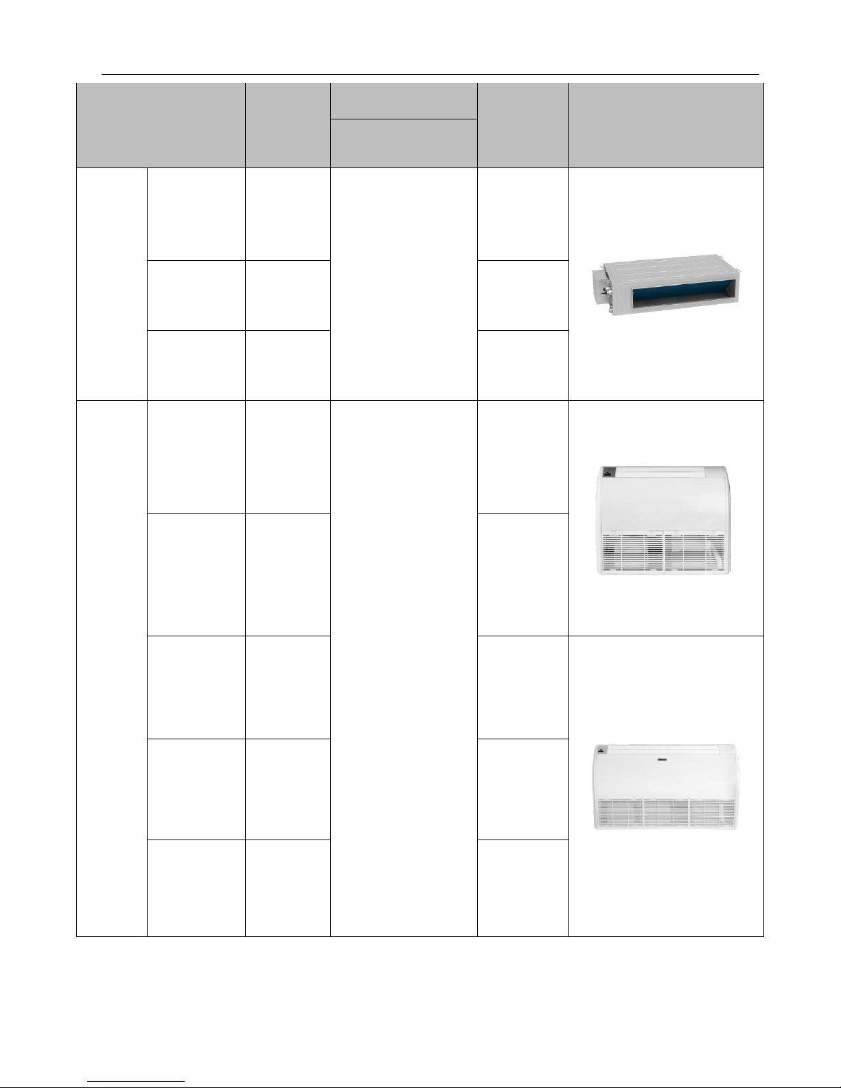
Duct Type
GUD100PH/A-T
10.0/12.0
220-240V 1N~50Hz
208-230V 1N~60Hz
CF022N1590
GUD125PH/A-T
12.1/13.5
CF022N1570
GUD140PH/A-T
13.4/15.5
CF022N1550
GUD160PH/A-T
16.0/17.0
CF022N1530
GUD35PS/A-T
3.5/4.0
CF022N1640
GUD50PS/A-T
5.0/5.5
CF022N1620
GUD71PS/A-T
7.0/8.0
CF022N1660
GUD85PS/A-T
8.5/8.8
CF022N1600
GUD100PHS/A-T
10.0/12.0
CF022N1580
GREE U-Match 5 SERIES UNIT SERVICE MANUAL
6
Model
Rated
Cooling/
Hating
Capacity (kw)
Power Supply
Finished
Product Code
Appearance
V/Ph/Hz
Duct Type
GUD125PHS/A
-T
12.1/13.5
220-240V 1N~50Hz
208-230V 1N~60Hz
CF022N1560
GUD140PHS/A
-T
13.4/15.5
CF022N1540
GUD160PHS/A
-T
16.0/17.0
CF022N1520
Floor Ceiling
Type
GUD35ZD/A-T
3.5/4.0
220-240V 1N~50Hz
208-230V 1N~60Hz
ED020N1720
GUD50ZD/A-T
5.0/5.5
ED020N1730
GUD71ZD/A-T
7.0/8.0
ED020N1740
GUD85ZD/A-T
8.5/8.8
ED020N1750
GUD100ZD/A-T
10.0/12.0
ED020N1680
GREE U-Match 5 SERIES UNIT SERVICE MANUAL
7
Model
Rated
Cooling/
Hating
Capacity (kw)
Power Supply
Finished
Product Code
Appearance
V/Ph/Hz
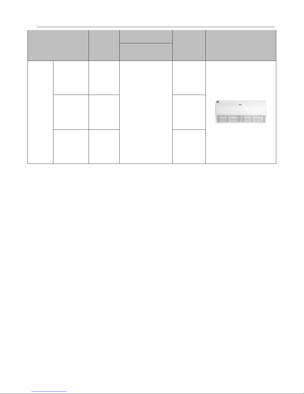
Floor
Ceiling
Type
GUD125ZD/A-T
12.1/13.5
220-240V 1N~50Hz
208-230V 1N~60Hz
ED020N1690
GUD140ZD/A-T
13.4/15.5
ED020N1700
GUD160ZD/A-T
16.0/17.0
ED020N1710
Note: The outdoor unit is generally suitable to any one of the three types of indoor units with no need of change (limited to cassette
type, duct type and floor ceiling type).
GREE U-Match 5 SERIES UNIT SERVICE MANUAL
8
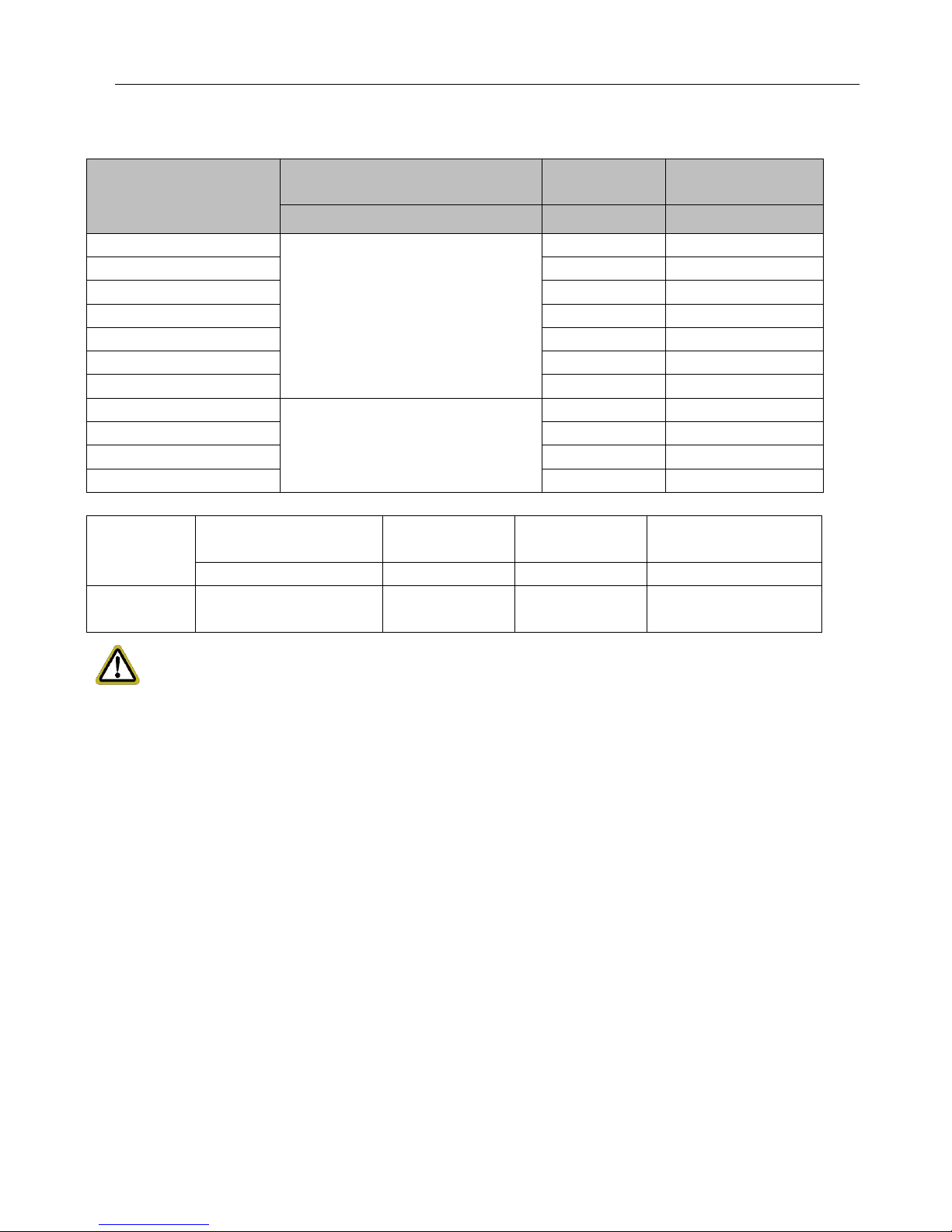
1.2 Electrical Parameters
Model
Power supply
Circuit breaker
capacity
Min. sectional area of
power cord
V/Ph/Hz
A
mm2
GUD35W/NhA-T
220-240V 1N~50Hz
208-230V 1N~60Hz
16
1.5
GUD50W/NhA-T
16
1.5
GUD71W/NhA-T
20
2.5
GUD85W/NhA-T
25
2.5
GUD100W/NhA-T
32
4.0
GUD125W/NhA-T
32
4.0
GUD140W/NhA-T
40
6.0
GUD100W/NhA-X
380-415V 3N~50Hz/60Hz
16
1.5
GUD125W/NhA-X
16
1.5
GUD140W/NhA-X
16
1.5
GUD160W/NhA-X
16
1.5
Model
Power Supply
Fuse Capacity
Circuit Breaker
Capacity
Min. Sectional Area of
Power Cord
V/Ph/Hz
A A mm2
Indoor unit
220-240V 1N~50Hz
208-230V 1N~60Hz
3.15 6 1.0
NOTICE:
① Fuse is located on the main board.
② Install a circuit breaker at every power terminal near the units (indoor and outdoor units) with at least 3mm contact gap. The
units must be able to be plugged or unplugged.
③ Circuit breaker and power cord specifications listed in the above table are determined based on the maximum power input of
the units.
④ Specifications of power cords listed in the above table are applicable in a working condition where ambient temperature is 40℃
and multi-core copper cable (e.g. YJV copper cable, with insulated PE and PVC sheath) is protected by a conduit, and is
resistant to 90℃ in maximum (See IEC 60364-5-52). If working condition changes, please adjust the specifications according
to national standards.
⑤ Specifications of circuit breaker are based on a working condition where the working temperature is 40℃. If working condition
changes, please adjust the specifications according to national standards.
⑥ Adopt 2pc of 0.75mm² power cords to be the communication cords between indoor and outdoor units. The maximum length is
100m. Please select a proper length according to local conditions. Communication cords must not be twisted together. To be in
compliance with EN 55014, it is necessary to use 8 meters long wire.
⑦ Adopt 2pc of 0.75mm² power cords to be the communication cords between wired control and indoor unit. The maximum
length is 30m. Please select a proper length according to local conditions. Communication cords must not be twisted together.
To be in compliance with EN 55014, it is necessary to use 7.5 meters long wire.
⑧ The wire gauge of communication cord should not be less than 0.75mm². It‘s recommended to use 0.75mm² power cords as
the communication cords.
GREE U-Match 5 SERIES UNIT SERVICE MANUAL
9
2. Control
2.1 Operation Mode
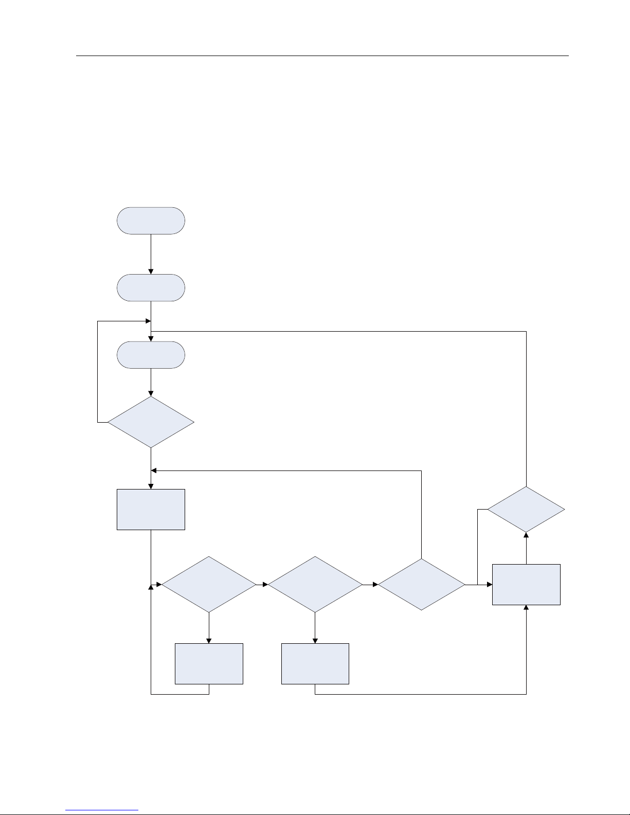
2.1.1 Cooling Mode
Power on
Cooling start
control
Indoor fan run
Satisfying open
Comp .condition
Comp. and
outdoor fan
run
Oil return IN
condition are met
Defrost IN
condition are met
Oil return
operation
Defrosting
operation
Temp of
indoor≤Set
temp
N
Y
N
N
Y Y
N
Comp. and
outdoor fan
stop
Y
Comp. stop
for 3 min
Y
N
GREE U-Match 5 SERIES UNIT SERVICE MANUAL
10
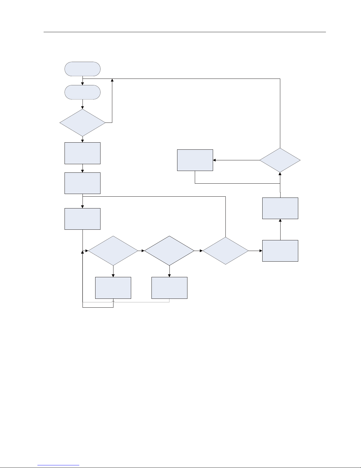
2.1.2 Heating Mode
Power on
Oil return IN
condition are met
Defrost IN
condition are met
Oil return
operation
Defrosting
operation
Temp of
indoor≤Set
temp
Y
N
Comp. and
outdoor fan
stop
Y
Comp. stop
for 3 min
Y
Y
Heating start
control
Satisfying open
Comp.condition
Comp. and
outdoor fan
run
Avoid cool
wind
indoor fan run
N
N
Y
N
N
indoor fan run
for 1 min
Comp. and
outdoor fan
stop
2.2 Control Mode
2.2.1 Based Control
2.2.1.1 Compressor Control
When cooling or heating mode is turned on, indoor fan will run for a while before the compressor starts. Under different modes,
the compressor can only be stopped after running for some time (special cases excluded). This is to protect the compressor from
frequent start or stop. Once the compressor is stopped, it must not be restarted right away. Please wait for a few minutes.
2.2.1.2 EXV Control
When the unit is first started, the electronic expansion valve will reset control. During the process, the expansion valve will
produce rattling sound. When cooling or heating mode is turned on, the valve will be open at a certain step before the compressor
starts.

GREE U-Match 5 SERIES UNIT SERVICE MANUAL
11
2.2.1.3 Outdoor Fan Control
This series air conditioner has two types of outdoor units: one with a single fan and the other with double fans. The outdoor fan
can run at the highest level 10 and the lowest level 1. By controlling the speed of outdoor fan, the unit can achieve cooling at low
temperature and heating at high temperature. In fan mode, outdoor fan will not work.
2.2.1.4 .4-way Valve Control
After heating mode is turned on for a while, 4-way valve will be energized to change the direction of refrigerant flow so that the
system can run in heating and the indoor unit will not blow cold air. Under other modes, the valve will not be energized.
To avoid the 4-way valve from incorrectly changing directions, when the unit stops in heating, due to a temperature point or
other protection reasons, the 4-way valve will continue to function temporarily and lose power after a while.
There must be adequate differential pressure for the 4-way valve to change directions.
2.2.2 Special Control
2.2.2.1 Defrosting Control
ODU defrosting control in heating: Defrosting will start when the temperature sensed by outdoor tube temperature sensor
reaches a preset value. During defrosting, the 4-way valve will switch to the cooling condition, and outdoor and indoor fans will both
stop. When the temperature sensed by outdoor tube temperature sensor reaches the preset value of defrosting stop, system will
quit defrosting. The 4-way valve will switch back to the heating condition, outdoor fan will start working first and indoor fan will
resume its previous fan speed after performing cold air prevention.
2.2.2.2 Oil Return Control
If the unit is running at low frequency for a long time, system will enable oil return control. This is to lead oil in the pipeline back
to the compressor so that the compressor will not be lack of oil. Generally, the oil return takes about 5min. The compressor running
frequency will be raised to the preset oil return frequency.
2.2.2.3 Refrigerant Recovery Control
Enabling method: Remote control and wired control both use the same enabling method. That is, within 5min after power is
connected, start cooling mode (turn on the unit) and set temperature at 16℃, then press “▲, ▼, ▲, ▼, ▲, ▼” (6 times of
pressing) in 5s to enter the refrigerant recovery mode. If it is successfully enabled, the indoor unit will display the corresponding
code E3.
After the refrigerant recovery mode is enabled, if remote control or wired control sends a signal or the refrigerant recovery
mode has been enabled for 10min, system will exit from refrigerant recovery. If outdoor unit is shut down because of malfunction,
refrigerant recovery will be stopped immediately.
Please note that refrigerant recovery mode cannot be enabled under the following conditions:
1. If temperature is shielded remotely, refrigerant recovery mode cannot be enabled. You need to first unlock the remote shield
against temperature.
2. If temperature is higher than 16 degrees under energy-saving mode, refrigerant recovery mode cannot be enabled. You
need to first turn off the energy-saving mode.
2.2.2.4 Forced Operation Control
This control is used to quickly check whether the unit can operate normally after installation. Wired control has to be used to
enable this control. For cassette type unit, you can enable the control through the light board.
Enabling method through the light board of cassette type unit: After the unit is installed and connected to power, press TEST
button on the light board to enter forced operation mode. Short-press TEST button (less than 2s), cooling mode will be activated.
Long-press TEST button (more than 2s), heating mode will be activated.
Enabling method through wired control:
Under power-on status,
Forced cooling: press the “▼” button continuously for 5s to enter the forced test mode;
Forced heating: press the“▲”button continuously for 5s to enter the forced test mode.

GREE U-Match 5 SERIES UNIT SERVICE MANUAL
12
During test mode, press any button to quit the test mode.
Note: Forced test mode can only be enabled when the unit is first turned on and not yet receives any remote control signal or
button control signal.
2.2.3 Protection Control
2.2.3.1 High Pressure Protection Control
System will enable high pressure protection control if the high pressure switch is detected open for continuously a little time.
Under high pressure protection, system will be shut down and display error code E1.
When high pressure protection occurs for the first time, system will restore operation if the high pressure switch is detected to
be reclosed for continuously a little time. When high pressure protection occurs for the second time in a certain time period, system
will not restore operation. You need to manually turn off the unit and clear the error before restarting up the unit. (If high pressure
protection occurs frequently, please send for professional personnel to repair.)
2.2.3.2 Low Pressure Protection Control
System will enable low pressure protection control if the low pressure switch is detected open for continuously a little time.
Under low pressure protection, system will be shut down and display error code E3. When low pressure protection occurs, system
will restore operation if the low pressure switch is detected to be reclosed within a few minutes after shutdown. If low pressure
protection occurs for several times in a period of time, system will not restore operation automatically. You need to manually turn off
the unit before restarting up the unit.
2.2.3.3 High Temperature Prevention Control
Under heating mode, system will enable high temperature prevention control if the temperature sensed by indoor tube
temperature sensor reaches a certain value. When high temperature prevention control is enabled, outdoor fan will slow down.
2.3 Functions
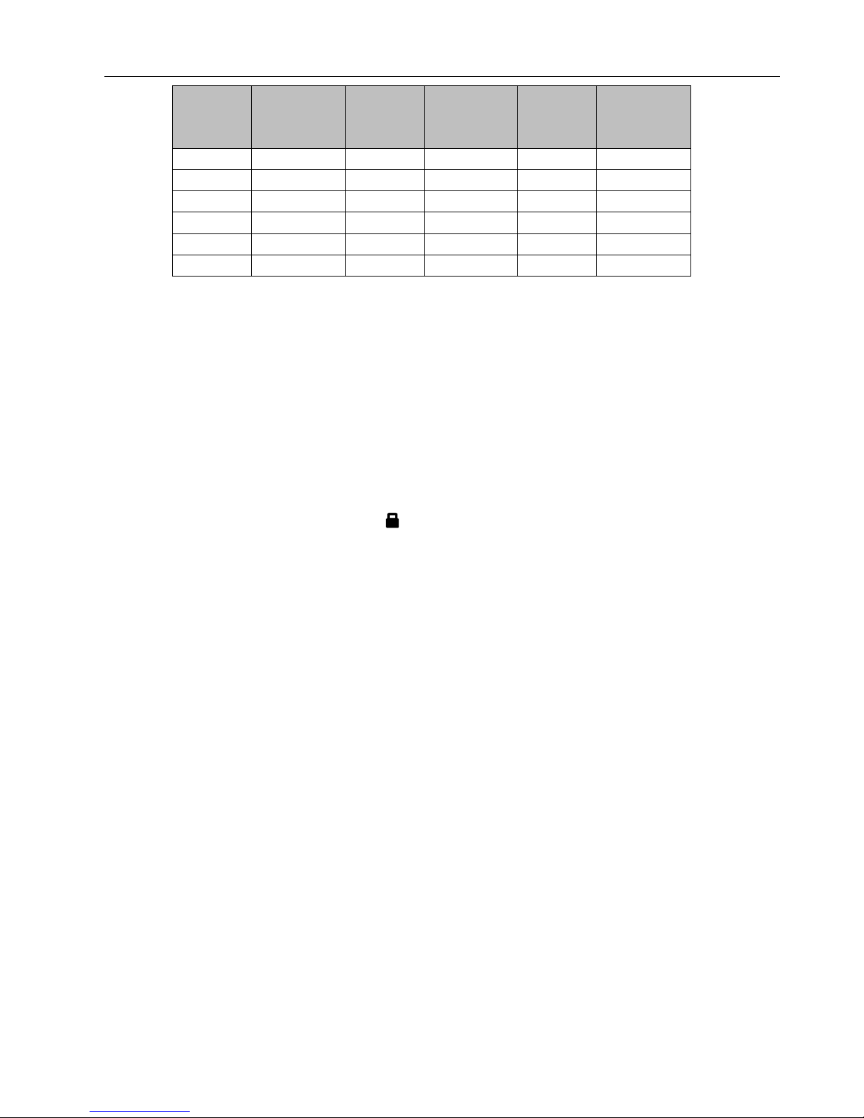
2.3.1 Setting of Filter Cleaning Reminder
When setting washing remind function, the timer area will display 2–bit number that means the pollution level, then press
“▲” and “▼” buttons to select, and press “SWING/ENTER” button to confirm the setting. Conversion relation between the
displayed pollution level and accumulative operating time are as the following list. After setting, when it reaches the washing time,
“CLEAN” icon will flash and remind, if you press “▲” and “▼” buttons to adjust the level, and press “SWING/ENTER”
button, then the accumulative time for filter washing remind will not be reset; if the time after adjustment is larger than the current
accumulative time, then “CLEAN” icon will stop flashing; if the time after adjustment is less than the current accumulative time,
then “CLEAN” icon will continue to flash.
The only method for cancelling the remind function is to press “FUNCTION” button to switch to “CLEAN” icon, and set
the timer area to be “00”, and then press “SWING/ENTER” button, then the accumulative time of filter washing remind is reset.
Pollution
Level
Accumulated
Operating
Time (hour)
Pollution
Level
Accumulated
Operating
Time (hour)
Pollution
Level
Accumulated
Operating
Time (hour)
10
5500
20
1400
30
100
11
6000
21
1800
31
200
12
6500
22
2200
32
300
13
7000
23
2600
33
400
GREE U-Match 5 SERIES UNIT SERVICE MANUAL
13
Pollution
Level
Accumulated
Operating
Time (hour)
Pollution
Level
Accumulated
Operating
Time (hour)
Pollution
Level
Accumulated
Operating
Time (hour)
14
7500
24
3000
34
500
15
8000
25
3400
35
600
16
8500
26
3800
36
700
17
9000
27
4200
37
800
18
9500
28
4600
38
900
19
10000
29
5000
39
1000
2.3.2 Low-temperature Drying Function
Under dry mode, when the setting temperature is 16°C, press “▼” button for twice, the setting temperature becomes
12°C, then the unit enters into low-temperature dry function.
When low-temperature dry function is turned on, directly press “▲” button or switch the mode can quit the function.
2.3.3 Child-lock Function
Without error, under ON or OFF status of unit, press “▲” and “▼” buttons simultaneously for 5 seconds can enter into
child-lock function, the liquid crystal screen will display “ ”; press “▲” and “▼” buttons simultaneously again for 5 seconds
can quit the child-lock function.
Under child-lock status, no response for pressing any buttons. The unit will memorize the child-lock status after power failure
and re-energizing the unit.
2.3.4 Memory Function
Under power-off status, press “MODE” and “▲” button simultaneously for 5 seconds can turn on or turn off memory
function. When memory function is set, “MEMORY”displays.
If memory function has not been set, when the unit is re-energized after power failure, the unit is power-off status. If the
memory function is set in wired controller, when the wired controller is re-energized after power failure, it will resume to the operating
status before power failure.
2.3.5 Door Control Function
When door control function is selected, the wired control will work when the room card is inserted and stop working when the
room card is pulled out. When door control function senses the room card is not inserted.
The setting method please refer to Debugging Function (2.3.9).
Note:
① . In long-distance monitoring or centralized control, no matter the room card is inserted or not, the ON/OFF of unit can be
controlled. If long-distance monitoring or centralized control information is received when the room card is not inserted.
When the card is reinserted, door control function is judged to be turned on. If long-distance monitoring or centralized
control information is received when the room card is inserted, it will keep the original status.
②. The unit can not be controlled by buttons when the card is not inserted.

GREE U-Match 5 SERIES UNIT SERVICE MANUAL
14
2.3.6 Switch between Fahrenheit and Degree Celsius
Under power-off status, press “MODE” and “▼” buttons simultaneously for 5 seconds, display board will switch between
degree Celsius and Fahrenheit.
2.3.7 Inquiry of Ambient Temperature
Under power-off or power-on status, press and hold “SWING/ENTER” button for 5 seconds to enter into ambient temperature
inquiry interface, then timer area displays the ambient temperature type 01 or 02, and ambient temperature area displays the
corresponding ambient temperature of corresponding type. In which, 01 refers to outdoor ambient temperature, 02 refers to indoor
ambient temperature. Press “MODE” button can switch between type 01 and 02. Press buttons other than “MODE” or when
the unit receives remote control signal, it will quit the inquiry status. If there is no any operation for 20 seconds, it will quit
automatically.
Note:
When the outdoor ambient temperature sensor detects the same temperature for 12 hours, it will shield the display of outdoor
ambient temperature sensor.
2.3.8 Inquiry of Historical Malfunction
Under off or on state of the unit, continuously press Function and ▼ buttons for 5s to view historical malfunction.
In enquiry state, set temperature displaying zone displays “00”. Press ▲ and ▼ buttons to view the 5 malfunctions
happened recently. The timer displaying position displays the specific error code. The 5th displayed malfunction is the last
malfunction.
2.3.9 Debugging Function
Under off state of the unit, press Function and Timer buttons at the same time for 5s to go to the debugging menu. Press Mode
button to adjust the setting items and press ▲ or ▼ button to set the actual value.
2.3.9.1 Setting ambient temperature sensor (dual ambient temperature sensors function)
Under debugging state, press Mode button to adjust to “00” in temperature displaying zone. Timer zone displays setting
state and press ▲ or ▼ button to adjust. There are 3 selections:
(1) The ambient temperature at air return is set as indoor ambient temperature (timer zone displays 01)
(2) The temperature at wired controller is set as indoor ambient temperature (timer zone displays 02)
(3) Select the temperature sensor at air return in cooling, dry and fan mode; select the temperature sensor at wired controller in
heating and auto mode.
2.3.9.2 Displaying setting of freeze protection error code
Under debugging state, press Mode button to adjust to “02” in temperature displaying zone. Timer zone displays setting
state and press ▲ or ▼ button to adjust. There are 2 selections:
(1) Displayed (LCD displays 01)
(2) Not displayed (LCD displays 02)
It is defaulted to be not displayed for export unit and be displayed for domestic unit.
2.3.9.3 Setting refrigerant lacking protection function
Under debugging state, press Mode button to adjust to “04” in temperature displaying zone. Timer zone displays setting

GREE U-Match 5 SERIES UNIT SERVICE MANUAL
15
state and press ▲ or ▼ button to adjust. There are 2 selections:
(1) With refrigerant lacking protection function (LCD displays 01)
(2) Without refrigerant lacking protection function (LCD displays 02)
2.3.9.4 Selecting blowing residual heating of indoor unit
Under debugging state, press Mode button to adjust to “05” in temperature displaying zone. Timer zone displays setting
state and press ▲ or ▼ button to adjust. There are 2 selections:
(1) Mode 1 (LCD displays 00)
(2) Mode 2 (LCD displays 01)
Note: Blowing residual heating of indoor unit
Mode 1: Unit stops when reaching temperature point and indoor fan motor does not stop in cooling mode; after unit stops when
reaching temperature point in heating mode, duct type unit and floor ceiling unit blow residual heat for 60s and then stop indoor unit,
while cassette type unit always operates in low fan speed and blows residual heat for 60s when there is malfunction.
Mode 2: After unit stops when reaching temperature point, the indoor fan motor stops operation with a 10s-delay no matter in
cooling mode or in heating mode.
2.3.9.5 Mode selecting of compressor electric heating belt
Under debugging state, press Mode button to adjust to “06” in temperature displaying zone. Timer zone displays setting
state and press ▲ or ▼ button to adjust. There are 2 selections:
(1) Mode 1 (LCD displays 00)
(2) Mode 2 (LCD displays 01)
Note:
Mode 1: Compressor electric heating belt starts when outdoor ambient temperature is below 35℃ and stops when outdoor
ambient temperature is above 37℃. When outdoor ambient temperature is within 35℃~ 37℃, the belt will keep its previous
operation state.
Mode 1: Compressor electric heating belt starts when outdoor ambient temperature is below -2℃ and stops when outdoor
ambient temperature is above 0℃. When outdoor ambient temperature is within -2℃~0℃, the belt will keep its previous operation
state.
2.3.9.6 Selecting low-power consumption mode
Under debugging state, press Mode button to adjust to “07” in temperature displaying zone. Timer zone displays setting
state and press ▲ or ▼ button to adjust. There are 2 selections:
(1) With low-power consumption mode (LCD displays 00)
(2) Without low-power consumption mode (LCD displays 01)
2.3.9.7 Selecting door control function
Under debugging state, press Mode button to adjust to “08” in temperature displaying zone. Timer zone displays setting
state and press ▲ or ▼ button to adjust. There are 2 selections:
(1) Without door control function (LCD displays 00)
(2) With door control function (LCD displays 01)
2.3.9.8 Selecting long-distance monitoring or centralized controller
Under debugging state, press Mode button to adjust to “10” in temperature displaying zone. Timer zone displays setting
state and press ▲ or ▼ button to adjust. There are 2 selections:
(1) Centralized controller (LCD displays 00)
(2) Long-distance monitoring (LCD displays 01)
2.3.9.9 Selecting fan mode of indoor fan motor
Under debugging state, press Mode button to adjust to “11” in temperature displaying zone. Timer zone displays setting state
and press ▲ or ▼ button to adjust.
a.There are 5 selections for low static pressure duct:
(1) P3 (LCD displays 03)
GREE U-Match 5 SERIES UNIT SERVICE MANUAL
16
(2) P4 (LCD displays 04)
(3) P5 (LCD displays 05)
(4) P6 (LCD displays 06)
(5) P7 (LCD displays 07)
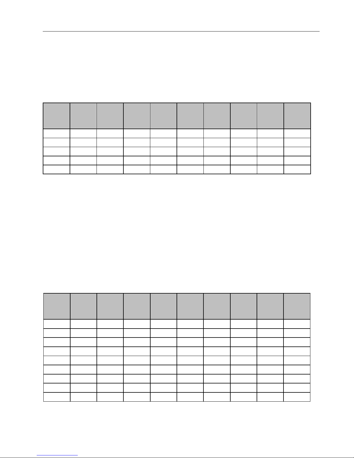
Note: You can select P03, P04, P05, P06, P07 in fan mode of indoor fan motor, which means different fan mode combinations
are corresponding to different static pressure. Ex-factory defaulted mode is P05. You can set the mode through wired controller. S01,
S02, S03„„S12, S13 means the rotation speed of indoor unit is from low to high.
Combination relationship of P03, P04, P05, P06, P07
Static
pressure
selection
Super
high
speed
High
speed
Medium
high
speed
Medium
speed
Medium
low speed
Low
speed
Quiet
R1 speed
Quiet
R2 speed
Quiet
R3 speed
P03
S09
S08
S07
S06
S05
S04
S03
S02
S01
P04
S10
S09
S08
S07
S06
S05
S04
S03
S02
P05
S11
S10
S09
S08
S07
S06
S05
S04
S03
P06
S12
S11
S10
S09
S08
S07
S06
S05
S04
P07
S13
S12
S11
S10
S09
S08
S07
S06
S05
b.There are 9 selections for high static pressure duct:
(1) P1 (LCD displays 01)
(2) P2 (LCD displays 02)
(3) P3 (LCD displays 03)
(4) P4 (LCD displays 04)
(5) P5 (LCD displays 05)
(6) P6 (LCD displays 06)
(7) P7 (LCD displays 07)
(8) P8 (LCD displays 08)
(9) P9 (LCD displays 09)
Note: You can select P01, P02, P03, P04, P05, P06, P07, P08, P09 in fan mode of indoor fan motor, which means different fan
mode combinations are corresponding to different static pressure. Ex-factory defaulted mode is P05. You can set the mode through
wired controller. S01, S02, S03„„S12, S13 means the rotation speed of indoor unit is from low to high.
Combination relationship of P01, P02, P03, P04, P05, P06, P07, P08, P09
Static
pressure
selection
Super
high
speed
High
speed
Medium
high
speed
Medium
speed
Medium
low speed
Low
speed
Quiet
R1 speed
Quiet
R2 speed
Quiet
R3 speed
P1
S05
S03
S02
S02
S01
S01
S01
S01
S01
P2
S06
S04
S03
S03
S02
S02
S02
S02
S02
P3
S07
S05
S04
S04
S03
S03
S03
S03
S03
P4
S08
S06
S05
S05
S04
S04
S04
S04
S04
P5
S09
S07
S06
S06
S05
S05
S05
S05
S05
P6
S10
S08
S07
S07
S06
S06
S06
S06
S06
P7
S11
S09
S08
S08
S07
S07
S07
S07
S07
P8
S12
S10
S09
S09
S08
S08
S08
S08
S08
P9
S13
S11
S10
S10
S09
S09
S09
S09
S09
2.3.9.10 Selecting compensation of temperature sensor at air return
Under debugging state, press Mode button to adjust to “12” in temperature displaying zone. Timer zone displays setting
state and press ▲ or ▼ button to adjust. There are 16 selections:
GREE U-Match 5 SERIES UNIT SERVICE MANUAL
17
(1) Compensate 0℃ (LCD displays 00)
(2) Compensate 1℃ (LCD displays 01)
(3) Compensate 2℃ (LCD displays 02)
(4) Compensate 3℃ (LCD displays 03)
(5) Compensate 4℃ (LCD displays 04)
(6) Compensate 5℃ (LCD displays 05)
(7) Compensate 6℃ (LCD displays 06)
(8) Compensate 7℃ (LCD displays 07)
(9) Compensate 8℃ (LCD displays 08)
(10) Compensate 9℃ (LCD displays 09)
(11) Compensate 10℃ (LCD displays 10)
(12) Compensate 11℃ (LCD displays 11)
(13) Compensate 12℃ (LCD displays 12)
(14) Compensate 13℃ (LCD displays 13)
(15) Compensate 14℃ (LCD displays 14)
(16) Compensate 15℃ (LCD displays 15)
Note: Indoor ambient temperature compensation can be set through the wired control (E.g.: If 02 is selected, it indicates the
compensation temperature is 2℃. If the indoor ambient temperature detected by the temperature sensor at air return is 29℃, the
ambient temperature after compensation is 29℃-2℃=27℃).
After finishing setting, press Enter/Cancel button to save and exit setting. After entering this interface, the system will exit this
menu if there is no operation on the button within 20s. Normal off state interface will be displayed and present setting will not be
saved.
2.3.10 Connect to Interface of Centralized Control
The indoor unit is with the interface of centralized controller. When centralized controller is connected, centralized control of unit
can be realized when the wired controller is not connected;
(1) Interface instruction:
1) The printing of interface on the indoor unit PCB is COM_BMS, before connecting the centralized controller,a gateway model
ME50-00/EG(M) is required , The following figure shows an example;
2) Electrical characteristic: none;
3) Working principle: centralized control the communication of indoor mainboard and realize the unit control;
(2) Function instructions:
In order to achieve this function, set the address mode and address through wired controller. Please refer to Point 3 for the
setting method. The address mode is defaulted to be connecting to centralized controller mode and the defaulted address is 1;
GREE U-Match 5 SERIES UNIT SERVICE MANUAL
18
When the centralized controller is connected, centralized control of the unit can be realized to control unit ON/OFF, operation
mode, set fan speed/temperature and weekly timer.
(3) Setting method:
1) Centralized control for up to 16 indoor units.
Firstly, set the address mode of wired controller into centralized controller address mode. The setting method is:
Under off state of the unit, press Function and Timer buttons at the same time for 5s to go to the debugging menu. Press Mode
button to adjust to ―10‖ in temperature displaying zone. Timer zone displays setting state and press ▲ or ▼ button to adjust. There
are 2 selections:
a. Centralized controller address mode (LCD displays 00)
b. Long-distance control address mode (LCD displays 01)
Choose the first selection and then press Enter/Cancel button to save and exit setting. Now, the address of wired controller is
set to match the address of centralized controller. The unit will memorize this setting status. The setting value will be memorized
after power failure.
Address setting of each unit: when the address mode is set to be centralized controller address mode. The address setting
value range is 01~16. The setting method is:
Under off state of the unit, press Function and Mode buttons at the same time for 5s to enter setting interface of wired controller
address. LCD displays address sequence. Press ▲ or ▼ button to adjust the address sequence and then press Enter/Cancel
button to confirm. The setting value will be memorized after power failure.
When the address is set, the wired controller can be removed and connect the centralized controller to the indoor mainboard.
Then connect the required units to realize centralized control of these units;
Note:
① When centralized controller is to be connected, set the address mode into centralized controller address mode through wired
controller. Long-distance control address mode can not be set;
② The unit addresses in the same network must be different, otherwise, communication malfunction will occur and the unit can not
work normally;
③ When centralized controller is to be connected, the unit address range is 1-16. Only 16 sets of unit in maximum can be
connected
④ The code and model of wired controller is as below:
Name
Product code
Remark
Centralized controller
CE50-24/E
MC207025
Only 16 sets of unit in
maximum can be connected to this controller
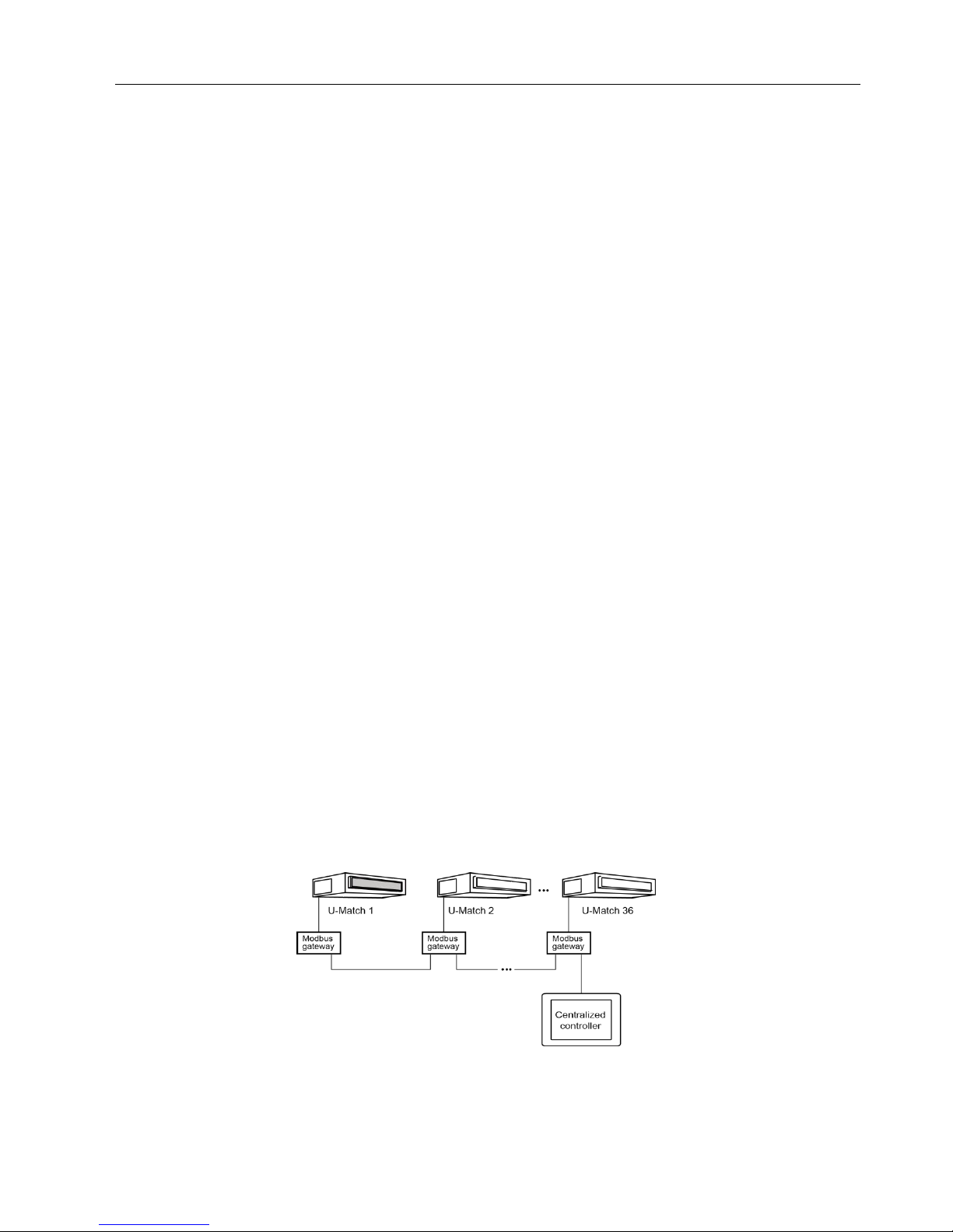
2) Centralized control for up to 36 indoor units.
Firstly, set the address mode of wired controller into Long-distance control address mode. The setting method is:
Under off state of the unit, press Function and Timer buttons at the same time for 5s to go to the debugging menu. Press Mode
button to adjust to ―10‖ in temperature displaying zone. Timer zone displays setting state and press ▲ or ▼ button to adjust. There
are 2 selections:
a. Centralized controller address mode (LCD displays 00)
b. Long-distance control address mode (LCD displays 01)
Choose the second selection and then press Swing/Enter button to save and exit setting. Now, the address of wired controller is
set to match the address of centralized controller. The unit will memorize this setting status. The setting value will be memorized
after power failure.
Address setting of each unit: when the address mode is set to be Long-distance control address mode. The address setting
value range is 01~36. The setting method is:
Under off state of the unit, press Function and Mode buttons at the same time for 5s to enter setting interface of wired controller
GREE U-Match 5 SERIES UNIT SERVICE MANUAL
19
address. LCD displays address sequence. Press ▲ or ▼ button to adjust the address sequence and then press Swing/Enter button
to confirm. The setting value will be memorized after power failure.
When the address is set, the wired controller can be removed and connect the centralized controller to the indoor mainboard.
Then connect the required units to realize centralized control of these units;
Note:
① The unit addresses in the same network must be different, otherwise, communication malfunction will occur and the unit can
not work normally;
② When centralized controller is to be connected, the unit address range is 1-36. Only 36 sets of unit in maximum can be
connected
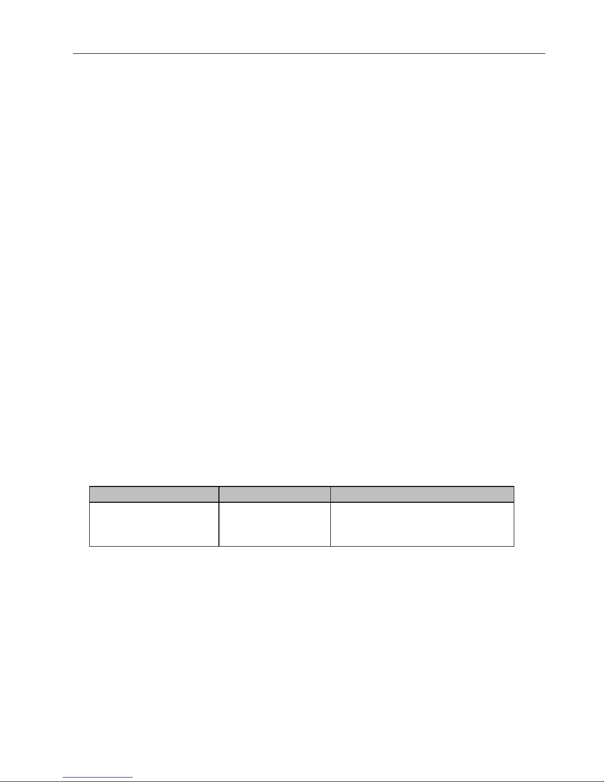
③ The code and model of wired controller is as below:
Name
Product code Remark
Centralized controller
CE52-24/F(C)
MC207052
Only 36 sets of unit in
maximum can be connected to this controller
3. Troubleshooting
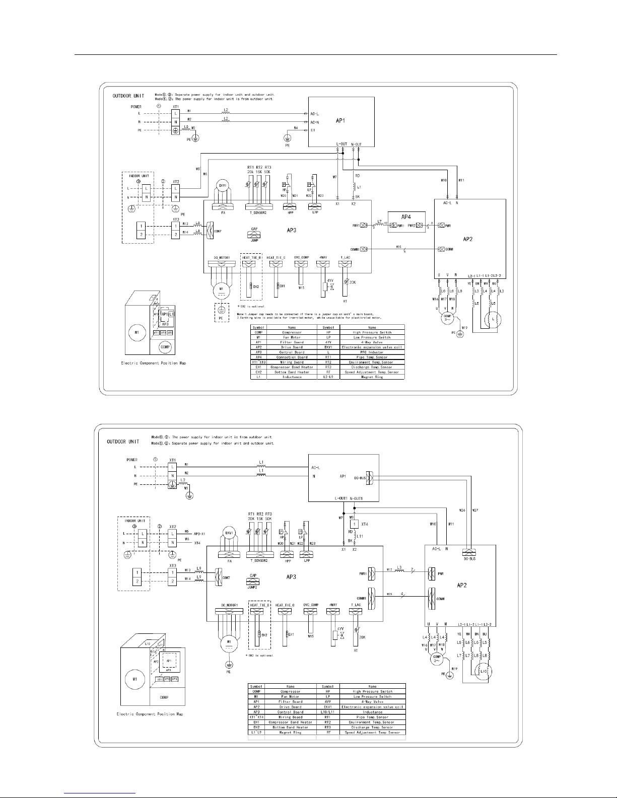
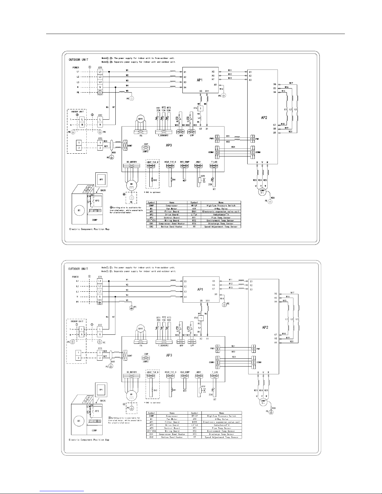
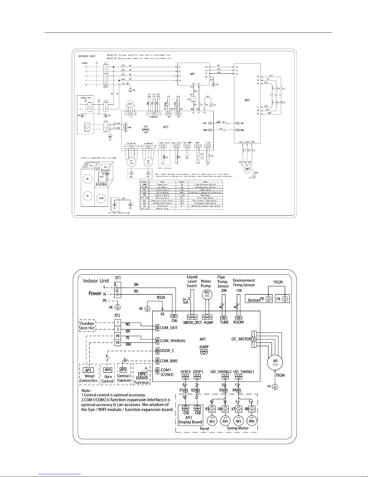
3.1 Wiring Diagrams
3.1.1 Wiring Diagrams of ODUs
Model:
GUD35W/NhA-T,
GREE U-Match 5 SERIES UNIT SERVICE MANUAL
20
Model:
GUD50W/NhA-T
Model: GUD71W/NhA-T, GUD85W/NhA-T
GREE U-Match 5 SERIES UNIT SERVICE MANUAL
21
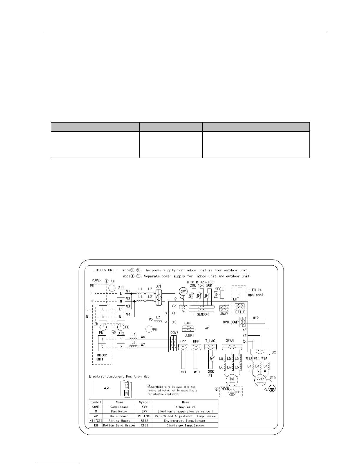
Model:GUD100W/NhA-T
Model:GUD125W/NhA-T, GUD140W/NhA-T
GREE U-Match 5 SERIES UNIT SERVICE MANUAL
22
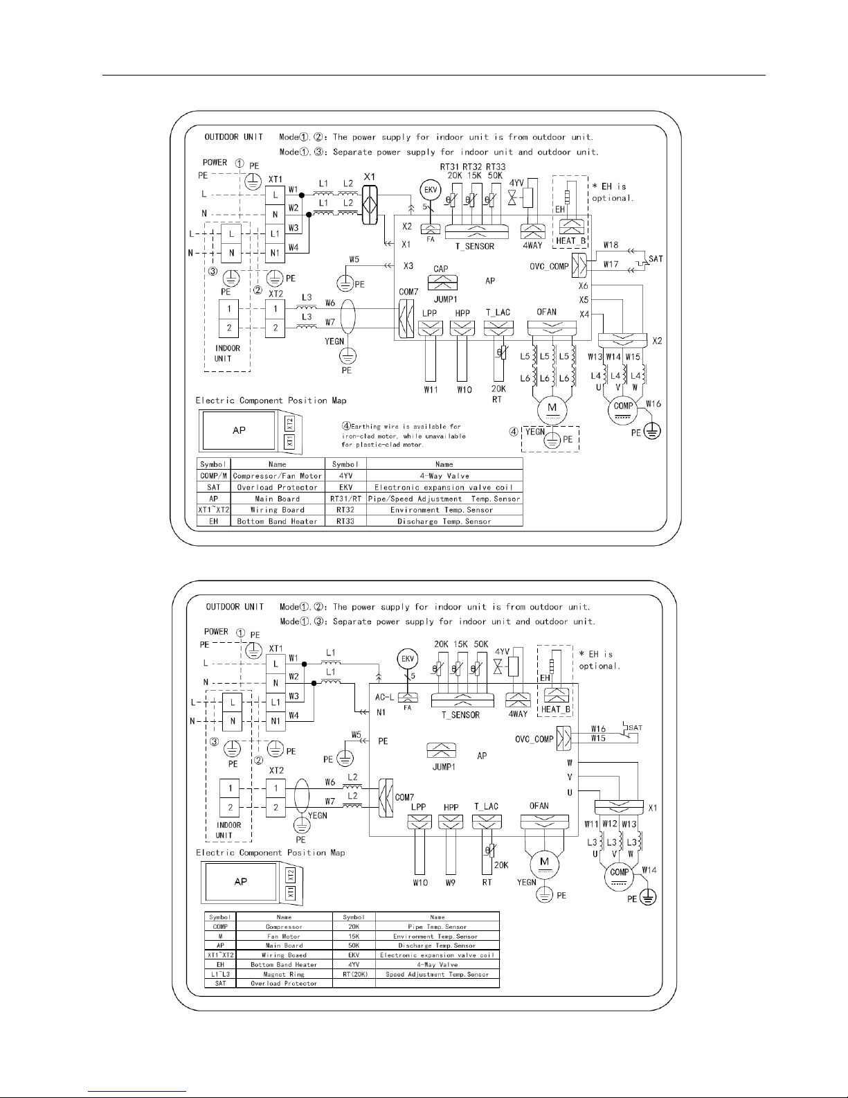
Model:GUD100W/NhA-X
GUD125W/NhA-X,GUD140W/NhA-X
GREE U-Match 5 SERIES UNIT SERVICE MANUAL
23
Model:GUD160W/NhA-X
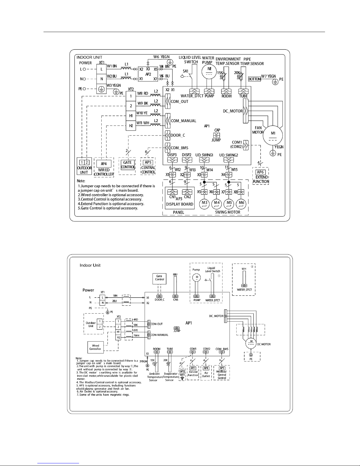
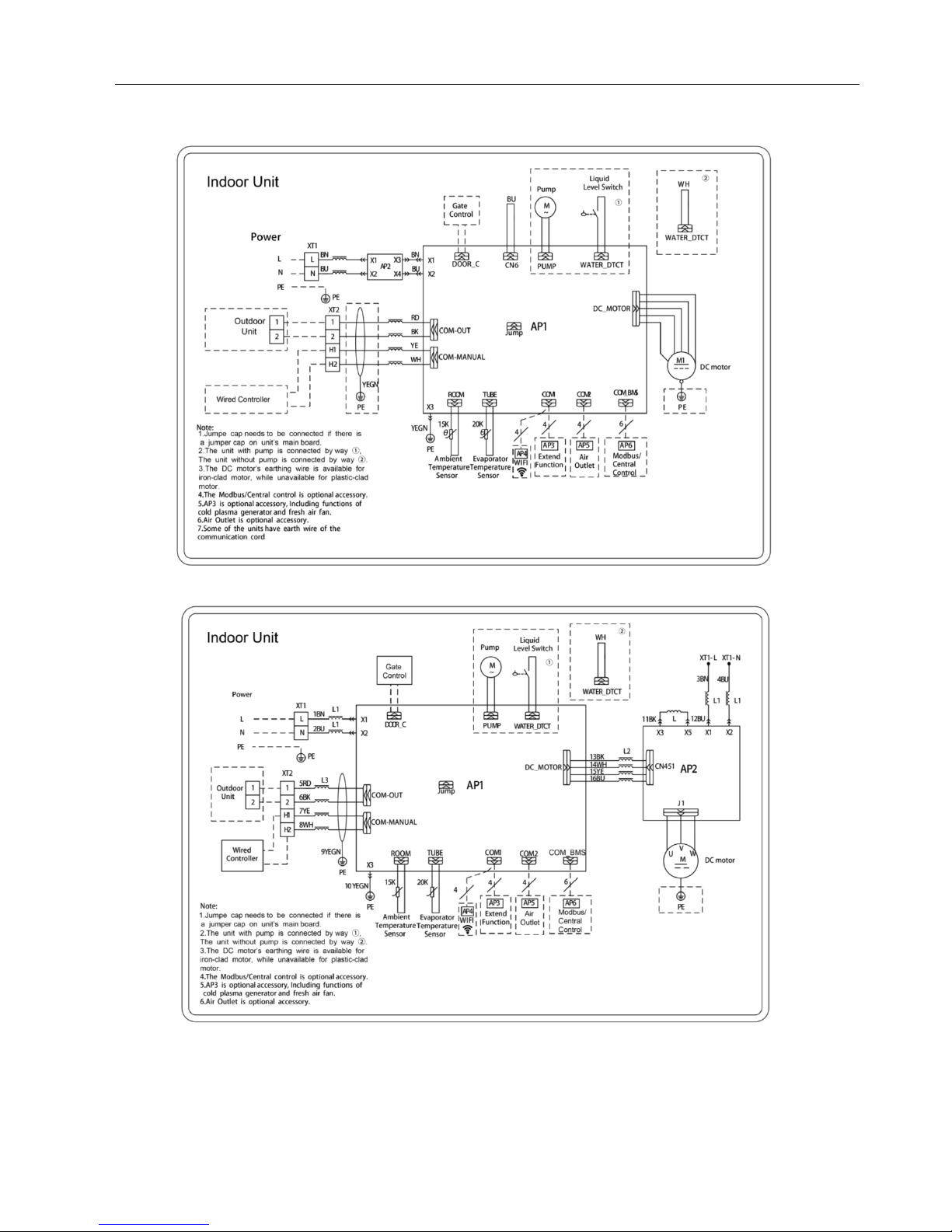
3.1.2 Wiring Diagrams of IDUs
Model: GUD35T/A-T, GUD50T/A-T
GREE U-Match 5 SERIES UNIT SERVICE MANUAL
24
Model: GUD71T/A-T, GUD85T/A-T, GUD100T/A-T, GUD125T/A-T, GUD140T/A-T, GUD160T/A-T
Duct Type
Model: GUD35P/A-T, GUD50P/A-T, GUD71P/A-T, GUD85P/A-T,
GUD35PS/A-T, GUD50PS/A-T, GUD71PS/A-T, GUD85PS/A-T
GREE U-Match 5 SERIES UNIT SERVICE MANUAL
25
Model: GUD100PH/A-T, GUD125PH/A-T, GUD140PH/A-T
GUD100PHS/A-T, GUD125PHS/A-T, GUD140PHS/A-T
Model: GUD160PH/A-T, GUD160PHS/A-T
 Loading...