

Gree KF-20x2GW/NA12, KFR-20x2GW/A12, KF-25x2GW/NA12, KF-32x2GW/NA12, KFR-25x2GW/A12 User Manual
...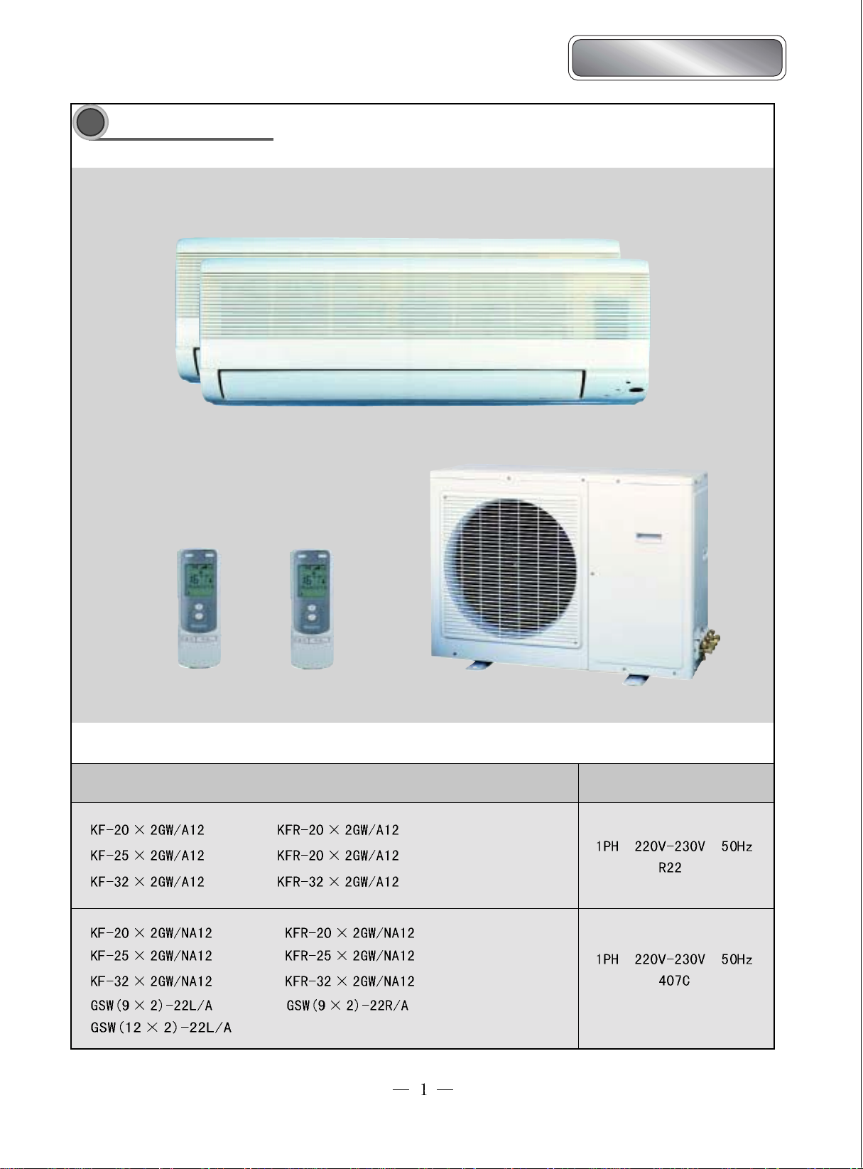
Summary and features
25
1
Bird Dual-Split Type
Models Remarks
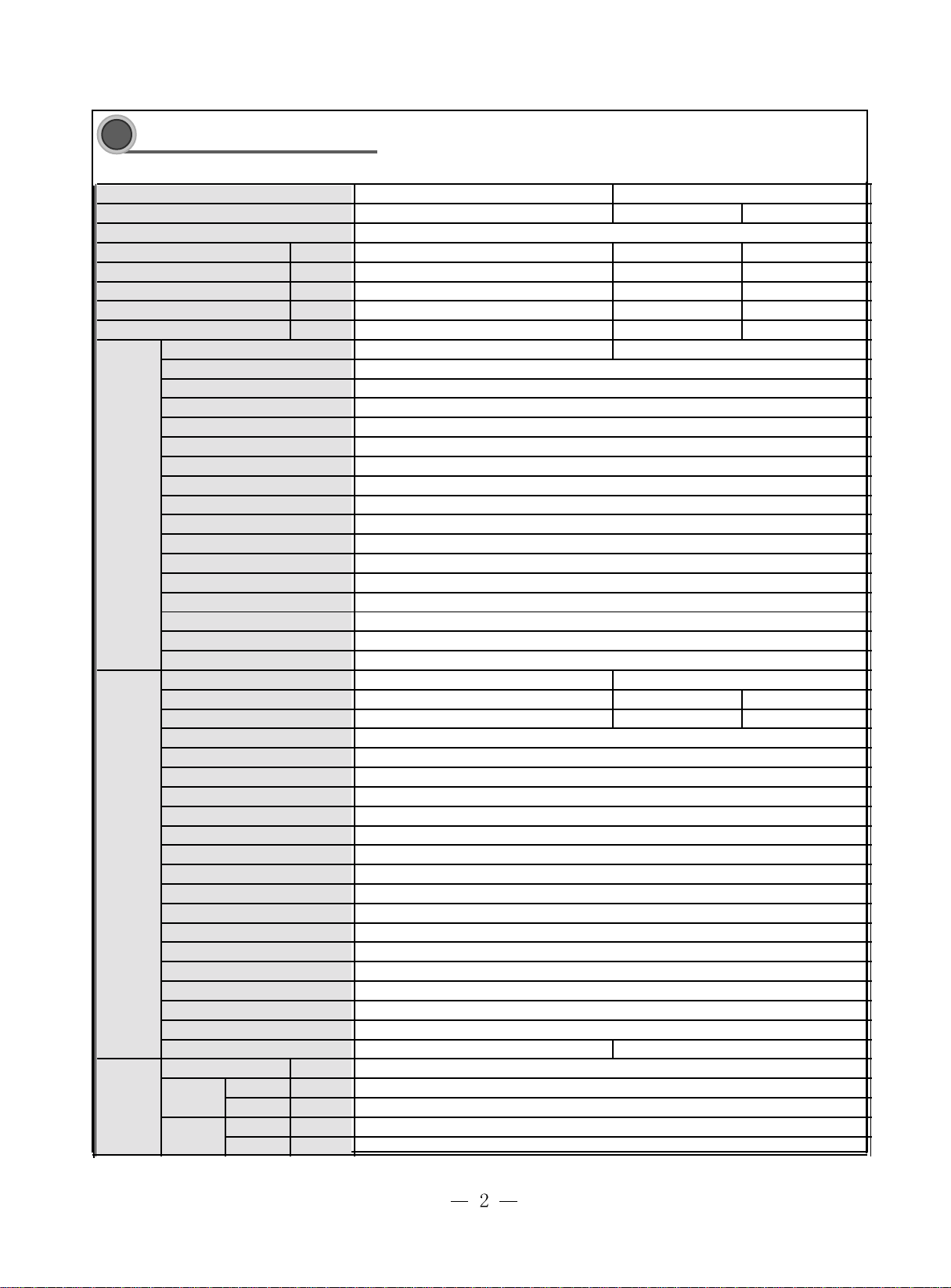
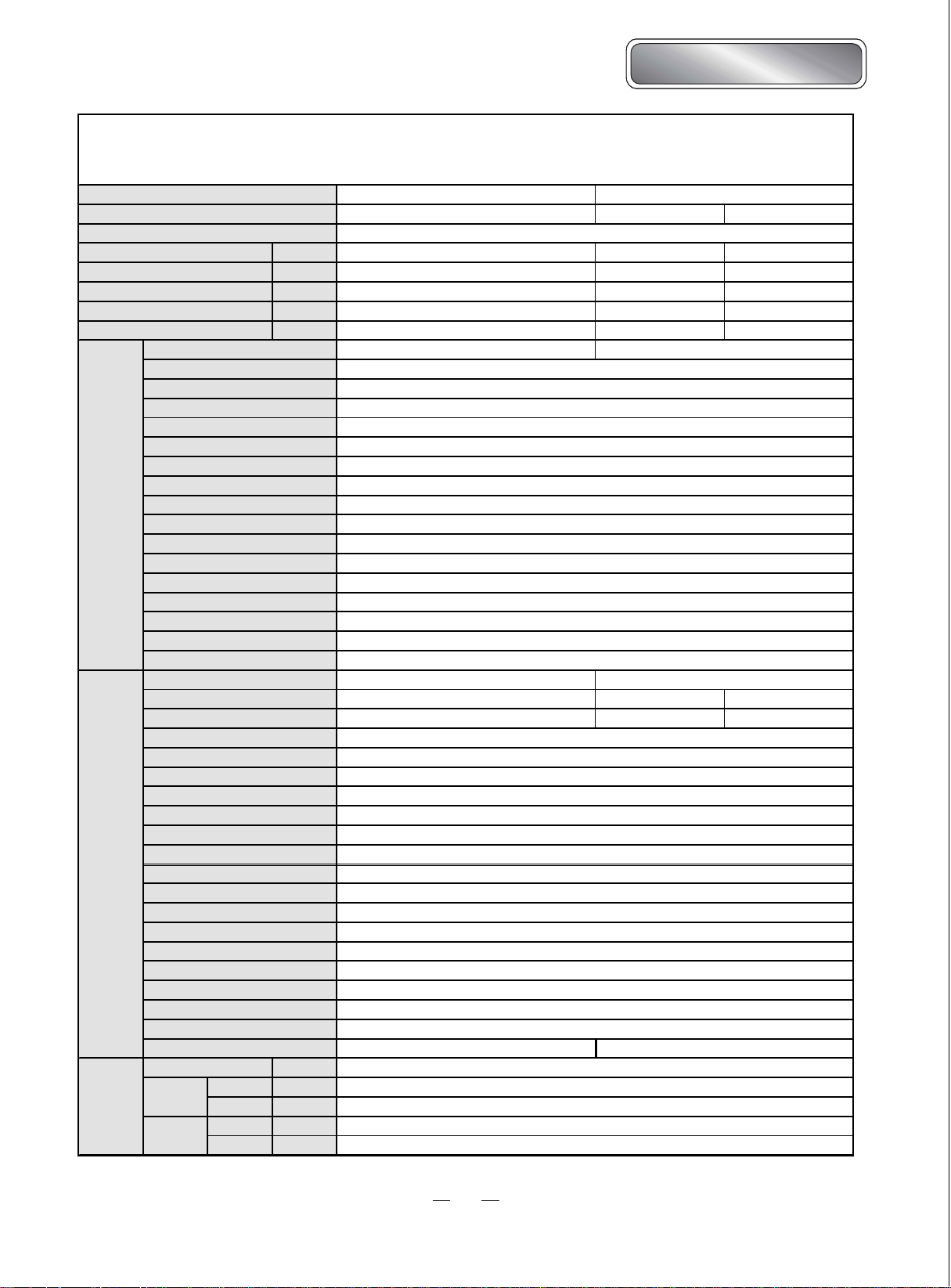
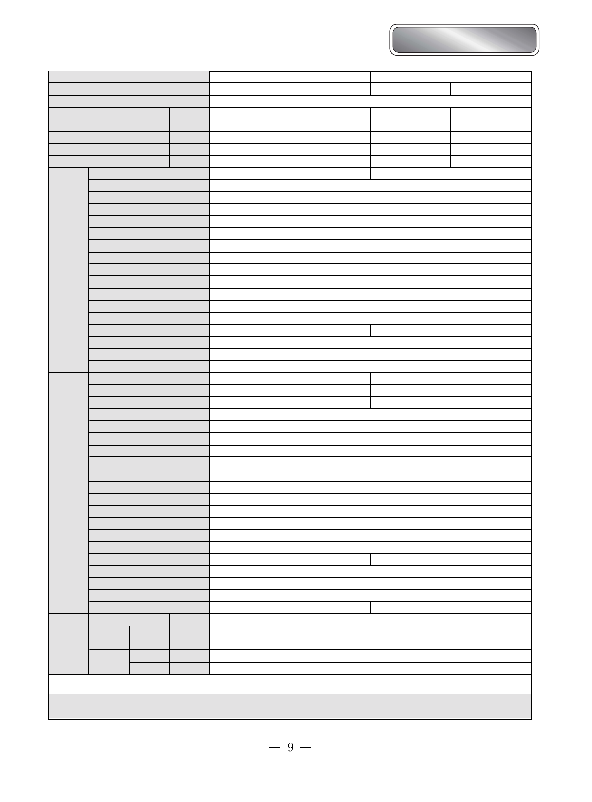
Technical and specifications
2
Model
KF-20×2GW/A12 KFR-20×2GW/A12
Function Cooling
Power supply(Phase-Frequency-Voltage)
Capaicty
Rated power
R ated current
Dehumidify volume
C.O.P/EER
Model
Fan speed
(r/min)(H/M/L)
Output power
F an type-piece C ross flow fan
Diameter-length(mm)
Evaporator
Pipe diameter
Indoor unit
Row- fin distance(mm)
Working area (m2)
Stepping motor
Motor power (W)
Control method/Fuse(A)
Running capacity
Noise
Outline dimension
Package dimension
Net weight/Gross weight(kg)
Model
Rated power
dB(A)
(W)
Rated current
(W)
(W)
(A)
(L/h)
(W/W)
) 8
(W
(μF)
(W/D/H)(mm)
(W/D/H)(mm)
(A)
Throttling method
Outdoor unit
Compressor type
Starting method
Working temperature
Condensor
Pipe diameter
Row- fin distance(mm)
Working area (m2)
(℃)
Fan motor power (W)/ speed (rpm)
Fan type-piece
Fan blade diameter
(mm)
Defrost method
Noise
Outline dimension
Package dimension
Net weight/Gross weight(kg)
dB(A)
(W/D/H)(mm)
(W/D/H)(mm)
Refrigerant/refrigerant charge(kg)
Connection
pipe
Length
Outer
diameter
Max.
distance
Liquid pipe
Gas pipe
Height
Length
(m)
(mm)
(mm)
(m)
(m)
1Ph 230V 50Hz
2000×2
770×2
3.4×2
0.7
2.6
KF-20×2G/A12 KFR-20×2G/A12
KF-20×2W/A12 KFR-20×2W/A12
R22/0.65×2 R22/0.9×2
2000×2 2300×2
770×2 750×2
3.4×2 3.33×2
0.76 -
2.8 3.07
960/900/850
1
—
97×585
φ
Aluminum fin-copper tube
7×0.41
φ
2-1.6
0.14
MP24GA
2
Controller 3.15A Transformer 0.2A
1
36
770×250×180
855×366×272
8.5/-
760
3.2
760 740
3.2 2.87
Capillary
-
Capacity
2-43
Aluminum fin-copper tube
9.52
φ
1-1.8
0.4
25/780
1
Axial flow fan
—
450
Auto defrost
57
950×710×412
-
65/-
4
6(1/4")
φ
9.52(3/8")
φ
5
10
HeatingCooling
℃
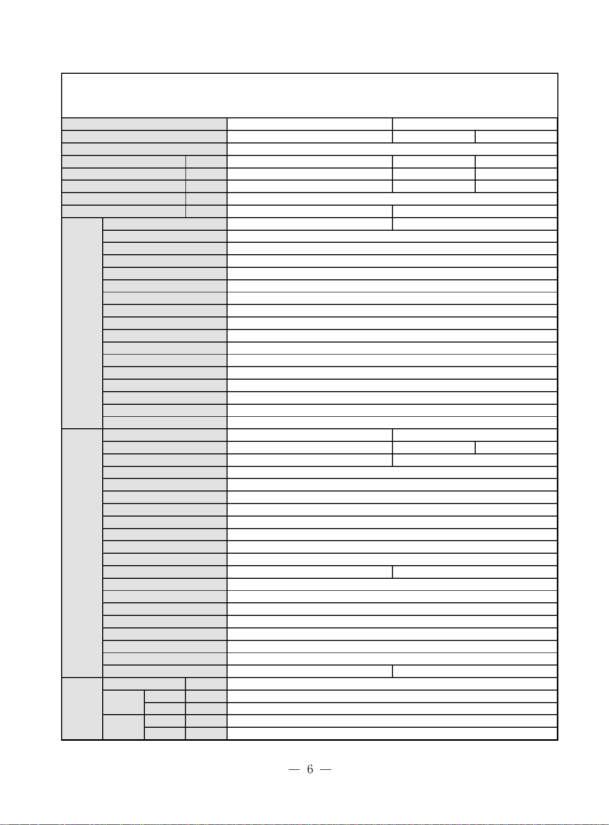
Bird Dual-Split Type
Bird Dual-Split type
Model
Function
Power supply(Phase-Frequency-Voltage)
Capaicty
Rated power
R ated current
Dehumidify volume
C.O.P/EER
Model
Fan speed
O utput power
Fan type-piece
Diameter-length(mm)
Evaporator
I ndoor unit
Outdoor unit
Connection
pipe
Pipe diameter
Row- fin distance(mm)
Working area (m2)
Stepping motor
Motor power (W)
Control method/Fuse(A)
Running capacity
Noise
dB(A)
Outline dimension
Package dimension
Net weight/Gross weight(kg)
Model
Rated power
Rated current
Throttling method
Compressor type
Starting method
Working temperature
Condensor
Pipe diameter
Row- fin distance(mm)
Working area (m2)
Fan motor power (W)/ speed (rpm)
Fan type-piece
Fan blade diameter
Defrost method
Noise
dB(A)
Outline dimension
Package dimension
Net weight/Gross weight(kg)
Refrigerant/refrigerant charge(kg)
Length
Outer
diameter
Max.
distance
Liquid pipe
Gas pipe
Height
Le ngth
(W)
(W)
(A)
(L/h)
(W/W)
(r/min)(H/M/L)
(W)
(μF)
(W/D/H)(mm)
(W/D/H)(mm)
(W)
(A)
(℃)
(mm)
(W/D/H)(mm)
(W/D/H)(mm)
(m)
(mm)
(mm)
(m)
(m)
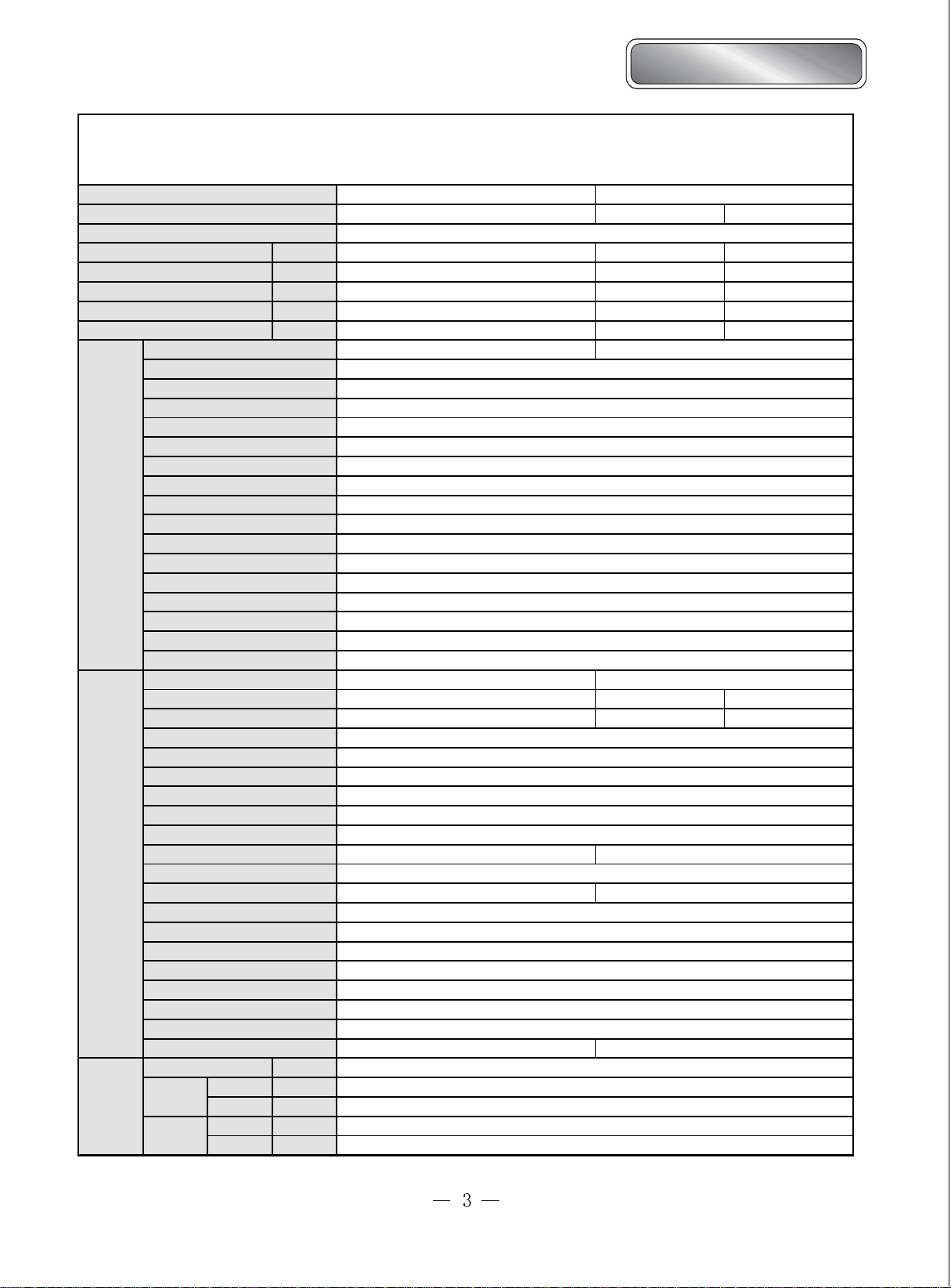
KF-25×2GW/A12 KFR-25×2GW/A12
Heating
1060/990/910
97×583
2-1.6
0.14
2
38
≤
770×250×180
8.5/-
Cooling
2500×2 2900×2
990×2 1040×2
4.3×2 4.55×2
1.2 -
2.53 2.79
13
1
—
1
-
975 1025
4.15 4.35
Cooling
1Ph 230V 50Hz
2500×2
790×2
4.3×2
1.2
2.53
KF-20×2G/A12 KFR-20×2G/A12
Cross flow fan
φ
Aluminum fin-copper tube
7×0.41
φ
MP24GA
Controller 3.15A Transformer 0.2A
KF-20×2W/A12 KFR-20×2W/A12
975
4.165
Capillary
855×366×272
Capacity
2-43
℃
Aluminum fin-copper tube
9.52
φ
1-2.0 1-1.6
0.4
38/700 60/780
Axial flow fan
—
1
450
Auto defrost
58
920×710×412
-
65/-
R22/0.8×2 R22/0.9×2
4
6(1/4")
φ
9.52(3/8")
φ
5
10
Model
Function
Power supply(Phase-Frequency-Voltage)
Capaicty
Rated power
R ated current
Dehumidify volume
C.O.P/EER
Model
Fan speed
O utput power
Fan type-piece
Diameter-length(mm)
Evaporator
I ndoor unit
Outdoor unit
Connection
pipe
Pipe diameter
Row- fin distance(mm)
Working area (m2)
Stepping motor
Motor power (W)
Control method/Fuse(A)
Running capacity
Noise
dB(A)
Outline dimension
Package dimension
Net weight/Gross weight(kg)
Model
Rated power
Rated current
Throttling method
Compressor type
Starting method
Working temperature
Condensor
Pipe diameter
Row- fin distance(mm)
Working area (m2)
Fan motor power (W)/ speed (rpm)
Fan type-piece
Fan blade diameter
Defrost method
Noise
dB(A)
Outline dimension
Package dimension
Net weight/Gross weight(kg)
Refrigerant/refrigerant charge(kg)
Length
Outer
diameter
Max.
distance
Liquid pipe
Gas pipe
Height
Le ngth
(W)
(W)
(A)
(L/h)
(W/W)
(r/min)(H/M/L)
(W)
(μF)
(W/D/H)(mm)
(W/D/H)(mm)
(W)
(A)
(℃)
(mm)
(W/D/H)(mm)
(W/D/H)(mm)
(m)
(mm)
(mm)
(m)
(m)
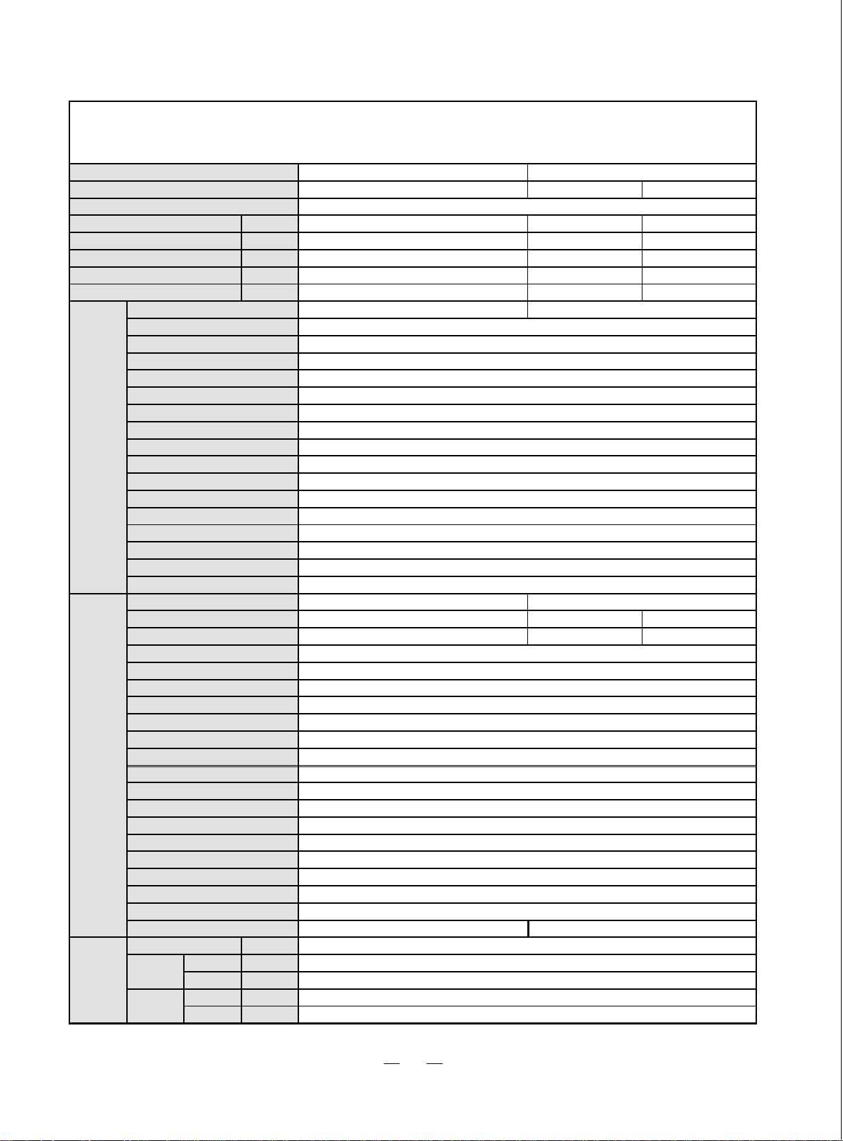
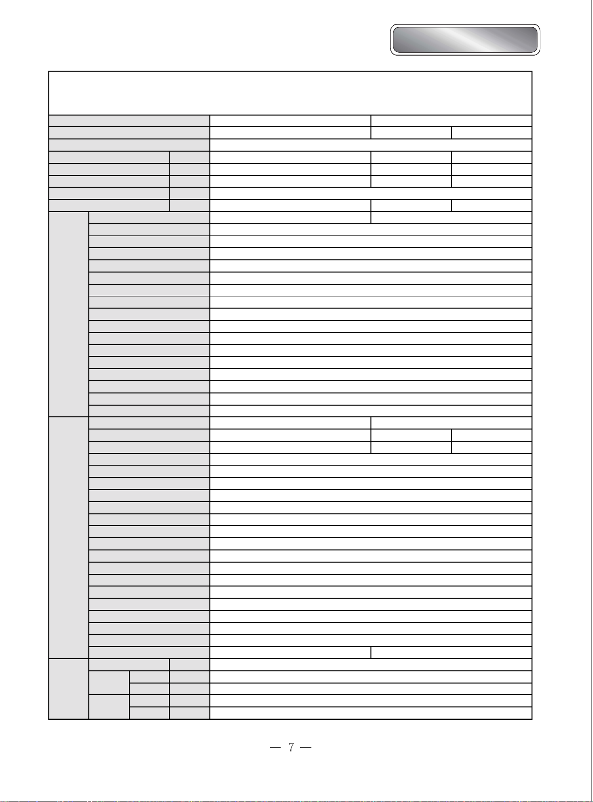
KF-32×2GW/A12 KFR-32×2GW/A12
Cooling
3200
×2
1360x2
1Ph 230V 50Hz
Cooling Heating
3200x2
1339x2
6.27x2 8.2x2 7.3x2
1.2
1.2 -
2.35 2.31
KF-32×2G/A12 KFR-32×2G/A12
1190/1090/990
14
Cross flow fan
97×583
φ
Aluminum fin-copper tube
7×0.41
φ
0.14
MP24GA
Transformer 0.2A
Controller 3.15A
KF-20×2W/A12 KFR-20×2W/A12
1344
6.07 8
≤
1
—
2-1.6
2
1
42
770×250×180
855x366x272
8.5/-
1323
Capillary
-
Capacity
≤T15℃
Aluminum fin-copper tube
9.52
φ
2-1.8
0.4
60/780
Axial flow fan
—
1
450
Auto defrost
60
840×412
950×
-
72/-
1.2×2 R22/1.25×2
R22/
4
6(1/4")
φ
12(1/2")
φ
5
10
3600x2
1426x2
2.76
1410
7.1
4
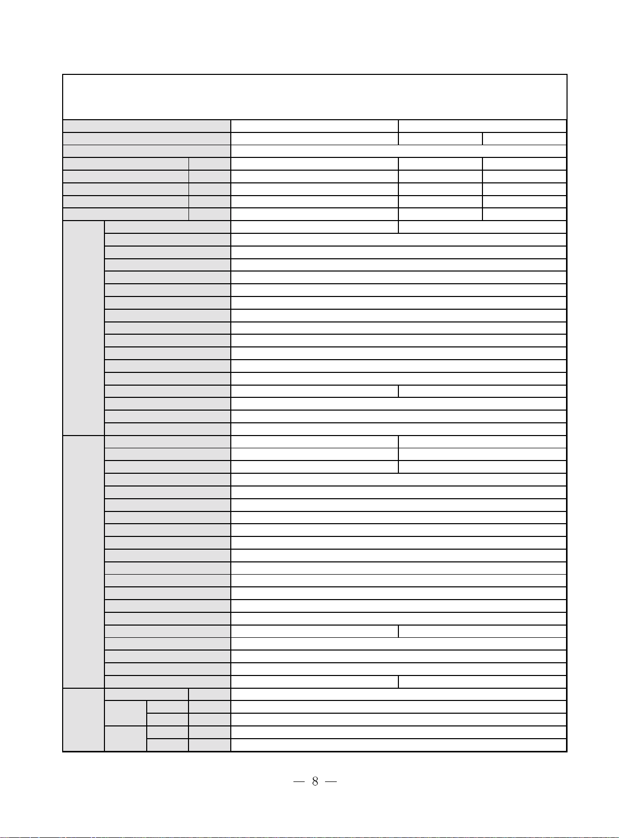
Bird Dual-Split Type
Bird Dual-Split type
Model
Function
Power supply(Phase-Frequency-Voltage)
Capaicty
Rated power
R ated current
Dehumidify volume
C.O.P/EER
Model
Fan speed
O utput power
Fan type-piece
Diameter-length(mm)
Evaporator
I ndoor unit
Pipe diameter
Row- fin distance(mm)
Working area (m2)
Stepping motor
Motor power (W)
Control method/Fuse(A)
Running capacity
Noise
dB(A)
Outline dimension
Package dimension
Net weight/Gross weight(kg)
Model
Rated power
Rated current
(W)
(W)
(A)
(L/h)
(W/W)
(r/min)(H/M/L)
(W)
(μF)
(W/D/H)(mm)
(W/D/H)(mm)
(W)
(A)
KF-20×2GW/NA12 KFR-20×2GW/NA12
Cooling
KF-
KF-20×2W/NA12 KFR-20×2W/NA12
Throttling method
Outdoor unit
Compressor type
Starting method
Working temperature
Condensor
Pipe diameter
Row- fin distance(mm)
Working area (m2)
(℃)
Fan motor power (W)/ speed (rpm)
Fan type-piece
Fan blade diameter
(mm)
Defrost method
Noise
dB(A)
Connection
pipe
Outline dimension
Package dimension
Net weight/Gross weight(kg)
Refrigerant/refrigerant charge(kg)
Outer
Max.
distance
Length
Liquid pipe
Gas pipe
Height
Le ngth
diameter
(W/D/H)(mm)
(W/D/H)(mm)
(m)
(mm)
(mm)
(m)
(m)
R407C/0.7×2 R407C/0.82×2
1Ph 220V-230V 50Hz
2000x2
850x2
3.7x2
0.7
2.5
20×2G/NA12 KFR-20×2G/NA12
1060/900/910
Cross flow fan
φ
Aluminum fin-copper tube
7×0.41
φ
MP24GA
Controller 3.15A
810
3.53 3.53
Transformer 0.2A
Cooling Heating
2000x2 2400x2
850x2 920x2
3.7x2
0.7 0.7
2.8
13
1
—
97×583
2-1.6
0.14
1.5
1
38
770×250×180
855x366x272
8.5/-
810
4.0x2
860
3.41
Capillary
-
Capacity
2-43
℃
Aluminum fin-copper tube
9.52
φ
1-1.8
0.4
80/790
450
—
1
Axial flow fan
Auto defrost
58
710×412
950×
-
65/-
4
6(1/4")
φ
9.52(3/8")
φ
5
10
2.8
5
Model
Function
Power supply(Phase-Frequency-Voltage)
Capaicty
Rated power
Rated current
Dehumidify volume
C.O.P/EER
Model
Fan speed
(r/min)(H/M/L)
(W)
(W)
(A)
(L/h)
(W/W)
KF-25×2GW/NA12 KFR-25×2GW/NA12
Cooling
1Ph 230V 50Hz
2500×2
1100×2
4.78×2
2.5 2.8
KF-25×2G/NA12 KFR-25×2G/NA12
Output power(W)
Fan type-piece
Diameter-length(mm)
Evaporator Aluminum fin-copper tube
Pipe diameter
Indoor unit
Outdoor unit
Connection
pipe
Row- fin distance(mm)
Working area (m2)
Stepping motor
Motor power (W)
Control method/Fuse(A)
Running capacity
Noise
dB(A)
Outline dimension
Package dimension
Net weight/Gross weight(kg)
Model
Rated power
Rated current
Throttling method Capillary
Compressor type
Starting method Capacity
Working temperature
Condensor Aluminum fin-copper tube
Pipe diameter
Row- fin distance(mm)
Working area (m2)
Fan motor power (W)/ speed (rpm)
Fan type-piece Axial flow fan
Fan blade diameter
Defrost method Auto defrost
Noise
dB(A)
Outline dimension
Package dimension
Net weight/Gross weight(kg)
Refrigerant/refrigerant charge(kg)
Length
Outer
diameter
Max
distance
(μF)
(W/D/H)(mm)
(W/D/H)(mm)
(W)
(A)
(℃)
(mm)
(W/D/H)(mm)
(W/D/H)(mm)
(m)
Liquid pipe
Gas pipe
Height
Length
(mm)
(mm)
(m)
(m)
KF-25×2W/NA12 KFR-25×2W/NA12
R407C/0.85×2 R407C/0.92×2
Controller 3.15A Transformer 0.2A
38/700 60/780
Cross flow fan
1030
4.2
1.2
1060/900/910
13
97×583
φ
7×0.41
φ
2-1.6
0.14
MP24GA
2
38
770×250×180
855×360×272
8.5/-
-
9.52
φ
1-1.8
0.4
—
58
65/-
4
6(1/4")
φ
9.52(3/8")
φ
5
10
Cooling
2500×2 2900×2
1080×2 1100×2
4.70×2 4.78×2
1
—
1
1030 1020
4.4
2-43
℃
1
400
950×710×412
-
Heating
Bird Dual-Split Type
Bird Dual-Split type
Model
Function
KF-32×2GW/NA12 KFR-32×2GW/NA12
Cooling Heating
Power supply(Phase-Frequency-Voltage)
Capaicty
Rated power
Rated current
Dehumidify volume
C.O.P/EER
(W)
(W)
(A)
(L/h)
(W/W)
Model
Fan speed
Output power
(r/min)(H/M/L)
(W)
3200×2
1390×2
13.5
2.3
KF-32×2G/NA12 KFR-32×2G/NA12
Fan type-piece Cross flow fan
Diameter-length(mm)
Evaporator
Pipe diameter
Indoor unit
Row- fin distance(mm)
Working area (m2)
Stepping motor
Motor power (W)
Control method/Fuse(A)
Running capacity
Noise
Outline dimension
Package dimension
(μF)
dB(A)
(W/D/H)(mm)
(W/D/H)(mm)
Net weight/Gross weight(kg)
Model
Rated power
Rated current
(W)
(A)
KF-32×2W/NA12 KFR-32×2W/NA12
1440
6
Throttling method
Outdoor unit
Connection
pipe
Compressor type
Starting method
Working temperature
Condensor
Pipe diameter
Row- fin distance(mm)
Working area (m2)
Fan motor power (W)/ speed (rpm)
Fan type-piece Axial flow fan
Fan blade diameter
Defrost method
Noise
Outline dimension
Package dimension
Net weight/Gross weight(kg)
Refrigerant/refrigerant charge(kg)
Length
Outer
diameter
Max.
distance
(℃)
(mm)
dB(A)
(W/D/H)(mm)
(W/D/H)(mm)
Liquid pipe
Gas pipe
Height
Length
(m)
(mm)
(mm)
(m)
(m)
R407C/1.20×2 R407C/1.25×2
Cooling
1Ph 230V 50Hz
3200×2 3800×2
1390×2 1490×2
13.5 14
/
2.3
1190/1090/990
8W
1
—
97×583
φ
Aluminum fin-copper tube
0.7×0.41
φ
2-1.4
/
MP24GA
2
—/3.15A
1
40
770×250×180
855×362×272
8.5/-
1280 1420
5.8 6.3
Capillary
-
Capacity
2-43
Aluminum fin-copper tube
9.52
φ
1-1.6
0.4
60/780
1
—
400
Auto defrost
62
950×710×412
-
70/-
4
6(1/4")
φ
12(1/2")
φ
5
10
2.55
℃
-
Model
Function
Power supply(Phase-Frequency-Voltage)
Capaicty
Rated power
Rated current
Dehumidify volume
C.O.P/EER
Indoor unit
Outdoor unit
Model
Fan speed
Output power(W)
Fan type-piece
Diameter-length(mm)
Evaporator
Pipe diameter
Row- fin distance(mm)
Working area (m2)
Stepping motor
Motor power (W)
Control method/Fuse(A)
Running capacity
Noise
Outline dimension
Package dimension
Net weight/Gross weight(kg)
Model
Rated power
Rated current
Throttling method
Compressor type
Starting method
Working temperature
Condensor
Pipe diameter
Row- fin distance(mm)
Working area (m2)
Fan motor power (W)/ speed (rpm)
Fan type-piece Axial flow fan
Fan blade diameter
Defrost method
Noise
Outline dimension
Package dimension
Net weight/Gross weight(kg)
Refrigerant/refrigerant charge(kg)
Length
Connection
pipe
Outer
diameter
Max. distance
(W)
(W)
(A)
(L/h)
(W/W)
(r/min)(H/M/L)
(μF)
dB(A)≤
(W/D/H)(mm)
(W/D/H)(mm)
(W)
(A)
(℃)
(mm)
(mm)
dB(A)
(W/D/H)(mm)
(W/D/H)(mm)
(m)
Liquid pipe
Gas pipe
Height
Length
(mm)
mm)
(m)
(m)
GSW(9×2)-22L/A GSW(9×2)-22R/A
Cooling HeatingCooling
1Ph 220V 50Hz
2500×2
870×2
4.03×2
1.2
2.78
GSW(9×2)-22L/A GSW(9×2)-22R/A
1050/960/900
20
Cross flow fan
97×583
φ
Aluminum fin-copper tube
7×0.41
φ
2-1.6
MP24GA
Controller 3.15A Transformer 0.2A
36 ≤37
8.5/-
GSW(9×2)-22L/A GSW(9×2)-22R/A
908 919
4.17 4.18
Capillary
Capacity
Aluminum fin-copper tube
9.52
φ
60/780
Auto defrost
56 58
65/-
R22/0.85×2 R22/0.95×2
6(1/4")
φ
9.52(3/8")
φ
10
2500×2 2900×2
970×2 1050×2
4.2×2 4.3×2
1.2
2.9 3.3
1
—
0.14
2
1
770×250×180
855×362×272
-
2-43
℃
2-1.8
0.4
1
—
450
950×710×412
-
4
5
-
Bird Dual-Split Type
Bird Dual-Split type
Model
GSW(12X2)-22L/A
Function Cooling
Power supply(Phase-Frequency-Voltage)
Capaicty
Rated power
Rated current
Dehumidify volume
C.O.P/EER
Indoor unit
Model
Fan speed
Output power(W)
Fan type-piece Cross flow fan
Diameter-length(mm)
Evaporator
Pipe diameter
Row- fin distance(mm)
Working area (m2)
Stepping motor
Motor power (W)
Control method/Fuse(A)
Running capacity
Noise
Outline dimension
Package dimension
Net weight/Gross weight(kg)
Model
Rated power
Rated current (A)
(W)
(W)
(A)
(L/h)
(W/W)
(r/min)(H/M/L)
(μF)
dB(A)
(W/D/H)(mm)
(W/D/H)(mm)
(W)
32000×2
1555.5
8.015
GSW(12×2)-22L/A
GSW(12×2)-22L/A GSW(9×2)-22R/A
Throttling method Capillary
Outdoor unit
Compressor type
Starting method
Working temperature
Condensor Aluminum fin-copper tube
Pipe diameter
Row- fin distance(mm)
Working area (m2)
Fan motor power (W)/ speed (rpm)
(℃)
2
)
(m
Fan type-piece Axial flow fan
Fan blade diameter
(mm)
Defrost method
Noise
dB(A)
Connection
pipe
Outline dimension
Package dimension
Net weight/Gross weight(kg)
Refrigerant/refrigerant charge(kg)
Length
Outer diamete r
Liquid pipe
Gas pipe
Max.
distance
(W/D/H)(mm)
(W/D/H)(mm)
(m)
(mm)
(mm)
Height
Length
(m)
(m)
R22/0.85×2
1Ph 220V 50Hz
2500×2 2900×2
970×2 1050×2
4.2×2 4.3×2
1.2
2.6
1200/1100/1000
14
—
97×538
φ
Aluminum fin-copper tube
7
φ
2-1.4
0.14
MP24GA
2
PCB 3.15A Transformer 0.2A
41/36(H/L)
855×362×272
8.5/12.5
- 919
-4
-
Capacity
9.52
φ
2-1.8
38/720
—
56
1100×450×775
65/70
4
6(1/4")
φ
12(1/2")
φ
5
10
1.2
2.9 3.3
1
1
770×180×250
2~43
℃
0.482
1
450
950×412×710
.18
The technical data are subject to change without notice. Please refer to the nameplate of the unit.
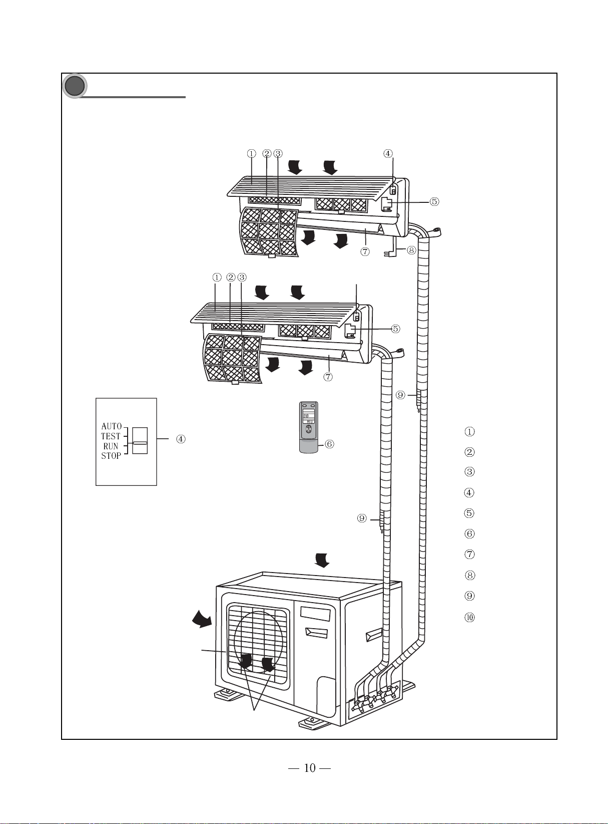
Spare part name
3
U nit B
Air in
Unit A
Air out
Air in
Air out
Front panel
Air cleaner
Filter
Manual switch
Covering plate
Wireless remote control
Air in
Guide louver
Power plug
Water drainage pipe
Air outlet grille
Air out
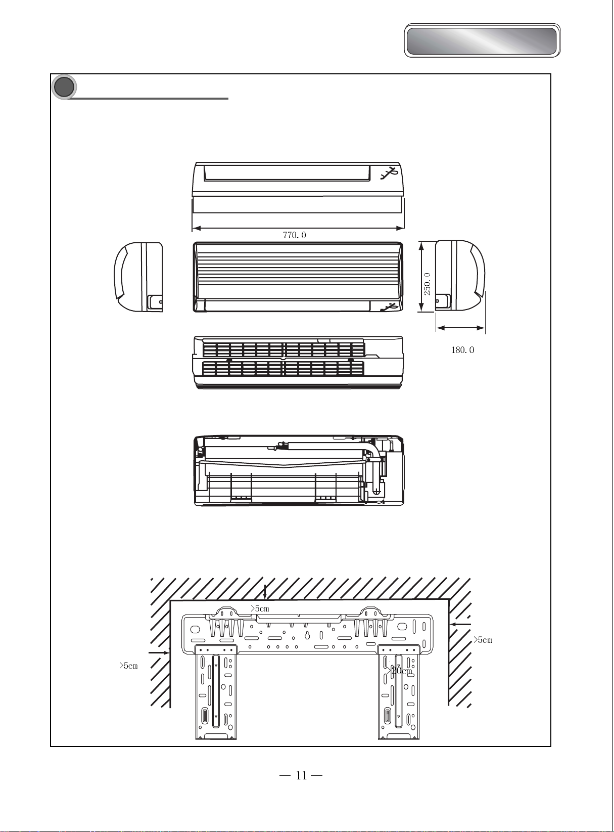
Outline and installation dimension
4
Bird Dual-Split Type
Bird Dual-Split type
Ceiling
Installation dimension

mm
Unit:
above
above
above
above
Screw
Nut
Spanner
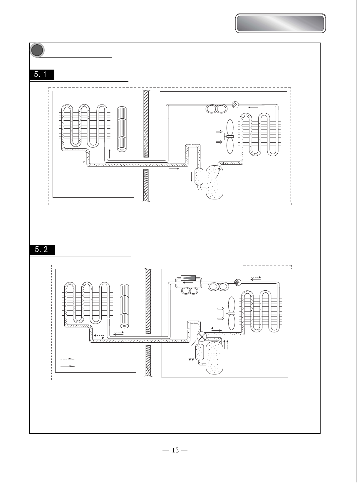
Cooling system diagram
5
Cooling system diagram for cooling only type
Bird Dual-Split type
Bird Dual-Split Type
Evaporator
Cross flow fan
Capillary
Filter
Axial flow fan
Condenser
Gas-liquid separator
Compressor
When the power is on, indoor and outdoor units will start to run. The compressor sucks low-pressure refrigerant gas from the evaporator
indoor unit and then discharges high-temperature, high-pressure refrigerant gas into outdoor condenser. Then air exchanges the heat with outdoor air
and becomes refrigerant liquid. The liquid is throttled by the capillary and changes into low-temperature and low-pressure liquid and then flows
into indoor evaporator. Then liquid exchanges the heat with the required air and changes into low-temperature and low-pressure refrigerant gas.
The cycle introduced above goes on and on, and the demanded low temperature environment is maintained.
of
Cooling system diagram for cooling/heating type
Evaporator
Heating
Cooling
When the power is on, indoor and outdoor units will start to run. When the system operates in cool mode, the compressor sucks low-temperature, lowpressure refrigerant gas from indoor evaporator and then discharges high-temperature, high-pressure refrigerant gas into outdoor heat exchanger. With
the help of axial flow fan, the gas transfers its latent heat into outdoor air and becomes high-pressure refrigerant liquid. The liquid is throttled by the
capillary and changes into low-temperature and low-pressure liquid and then flows into indoor heat exchanger. With the help of centrifugal fan, the
liquid evaporates into low-temperature refrigerant gas and indoor air is cooled down. The refrigerant gas is sucked into the compressor and the cycle
introduced above goes on and on, and the demanded low temperature environment is maintained.
When the system operates in heat mode, 4-way valve changes its way and the refrigerant flows into the reversible cycle as the cool mode. The
r
e frigerant discharges its latent heat in the indoor heat exchanger, and sucks heat from outdoor heat exchanger and forms the heat pump cycle.
T his cycle goes on and on, and the demanded high temperature environment is maintained.
Cross flow fan
One-way valve
Main capillary
Auxillary capillary
Axial flow fan
E lectromagnetic
4-way valve
Gas-liquid separator
Filter
Condenser
Compressor
6
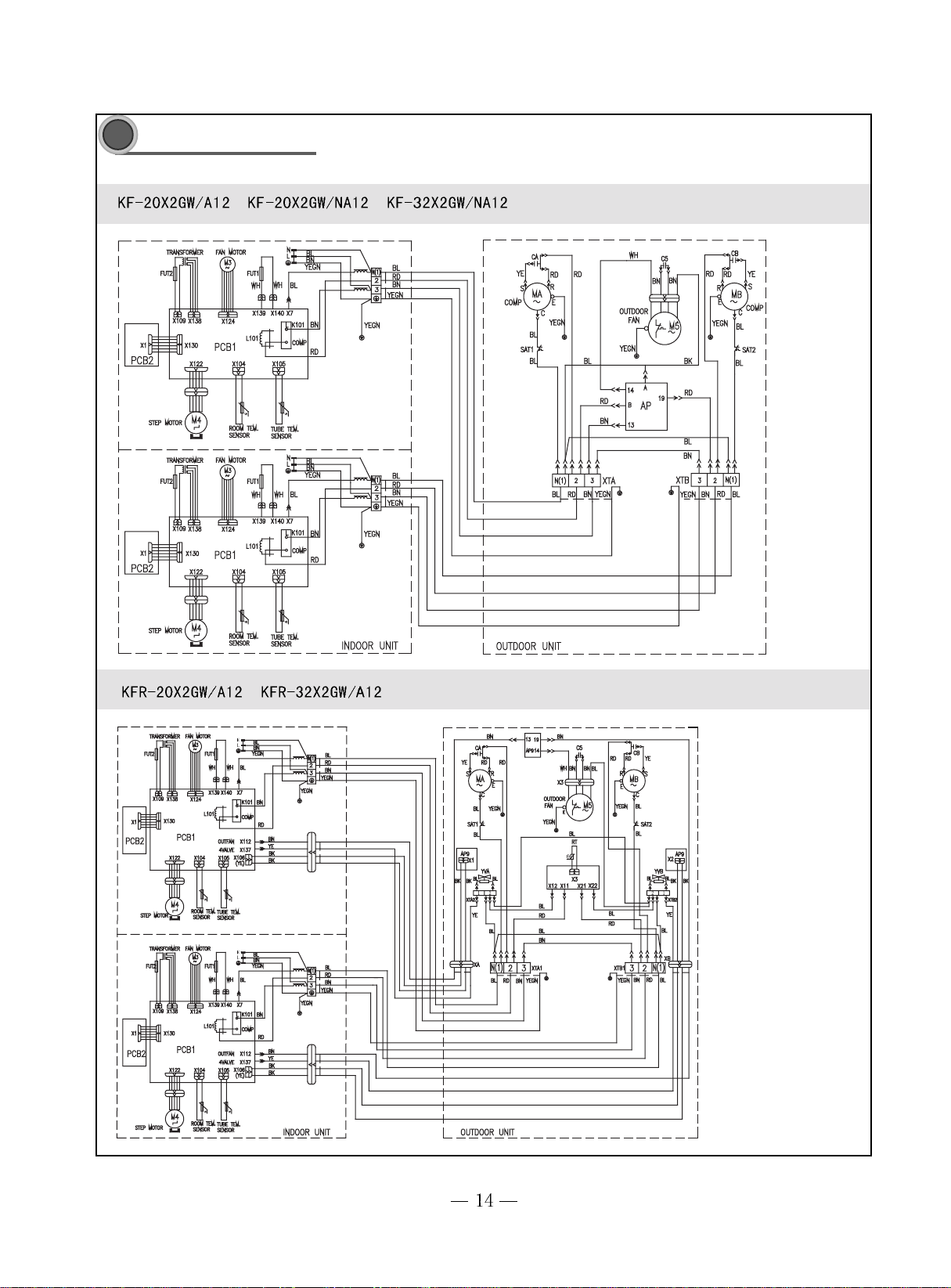
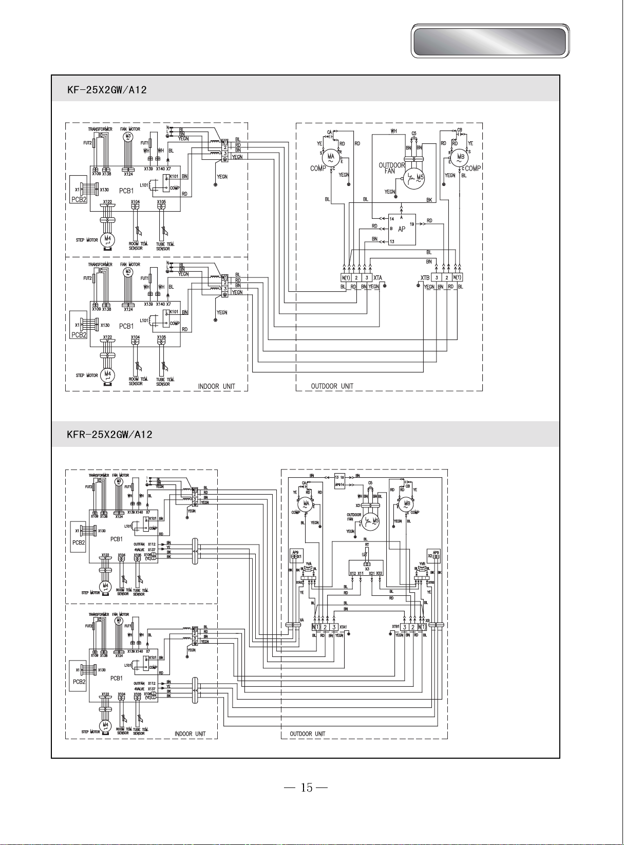
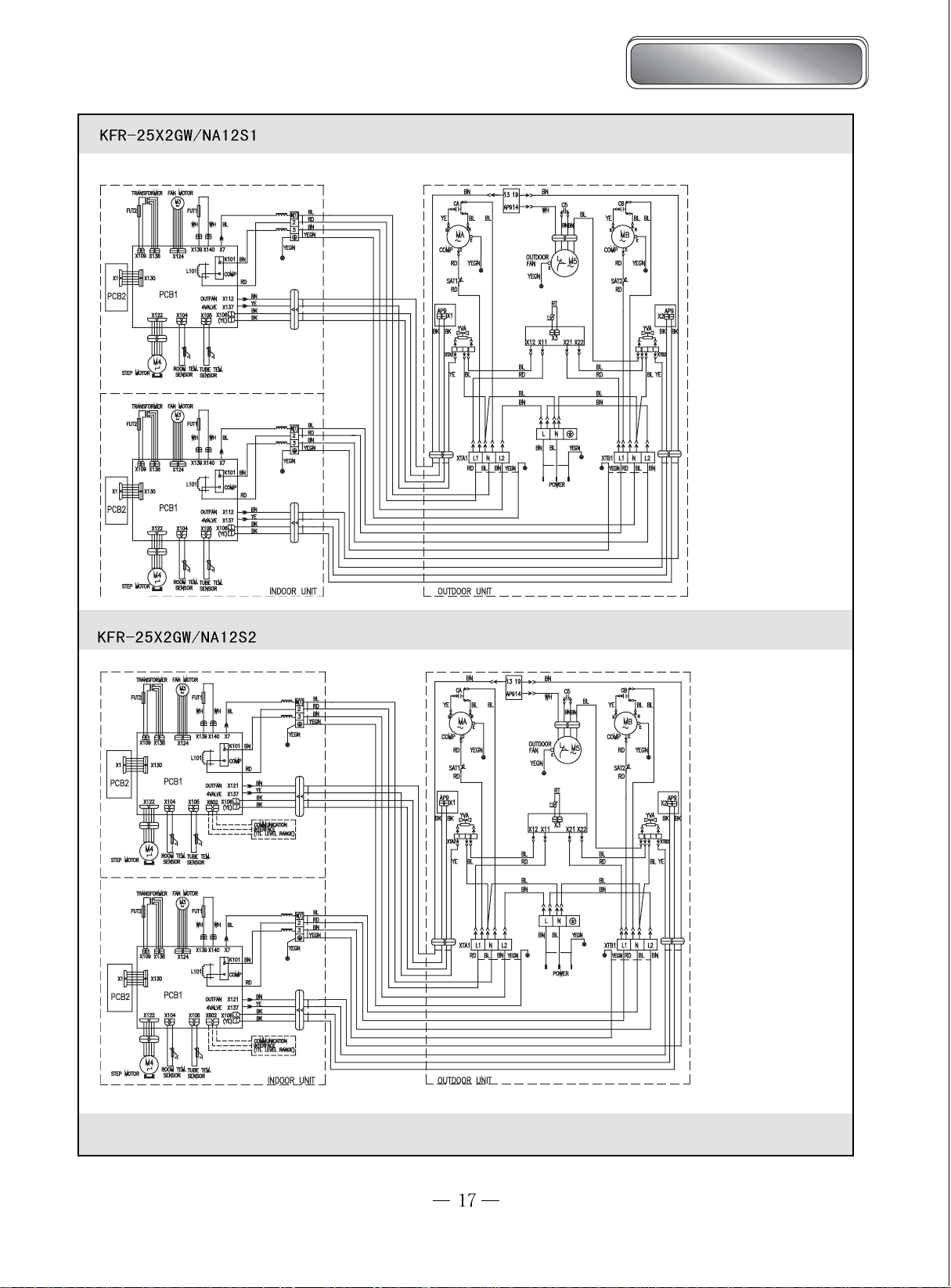
Circuit diagram
Bird Dual-Split type
Bird Dual-Split Type

Bird Dual-Split Type
Bird Dual-Split type
These circuit diagrams are subject to change without notice. Please refer to the ones stuck on the machines.
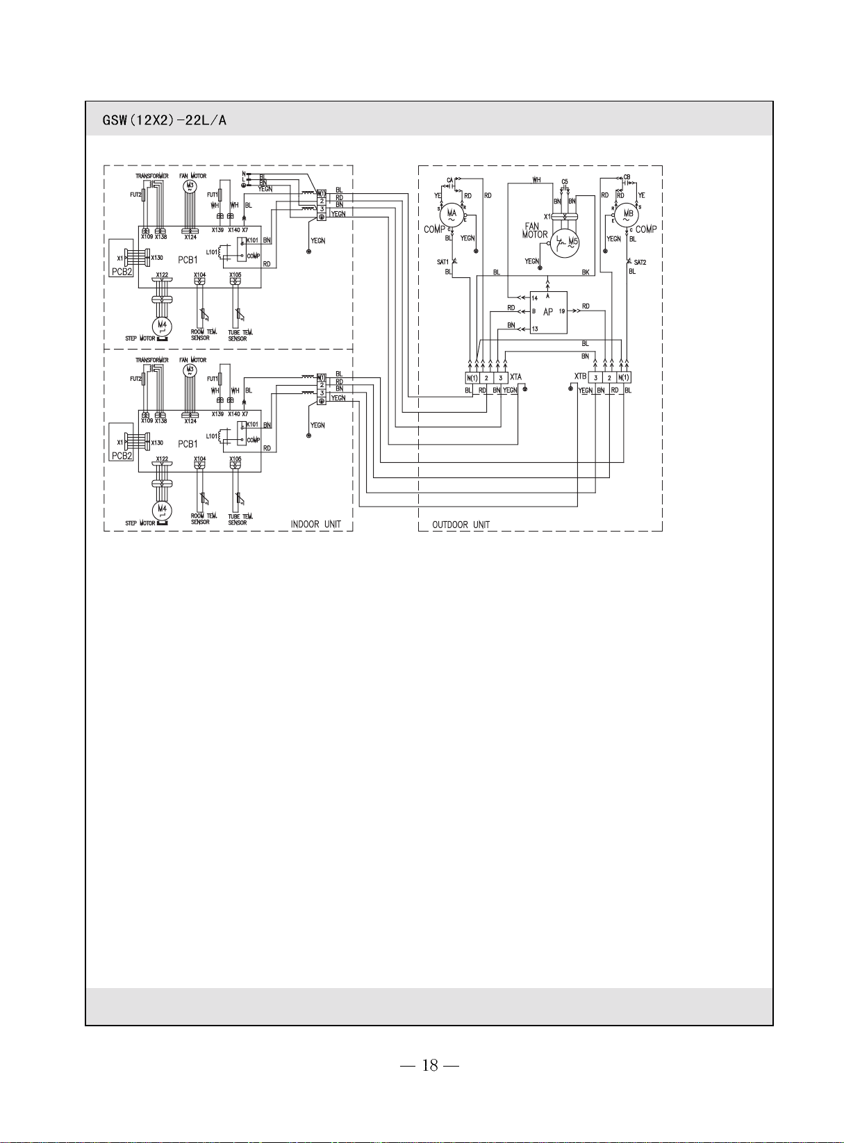
These circuit diagrams are subject to change without notice. Please refer to the ones stuck on the machines.
Bird Dual-Split Type
Tset
Tset
Ambient set
temp.Tamb
Start the cooling
Keep running in the old mode
Stopping the cooling
3Min
Run at the set speed
Run at the set speed
Running
Stop
Compressor
Outdoor fan
Indoor fan
Current
3Min
Running
Stop
Compressor
Outdoor fan
Indoor fan
Bird Dual-Split type
PCB function manual and operation method
77
7
77
PCB function manual
Temperature parameter
The room set temperature: (Tset)
The room ambient temperature:(Tamb)
The evaporator tube temperature: (Ttube)
The condenser tube temperature: (Tdefrost)
Foundamental functions
After power is on, no matter when compressor is started, the time span between the startups cannot be less than 3 minutes.
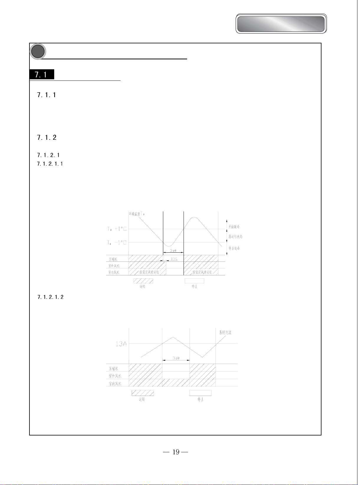
COOL mode
Cooling condition
If Tamb≥Tset+1℃, COOL mode will act, compressor and outdoor fan will run, indoor fan will run at the set speed.
If Tamb≤Tset-1℃,tunit will stop , compressor will stop and then outdoor fan will delay 15sec and stop.
If Tset-1℃<Tamb<Tset+1℃, the unit will keep running in the old mode.
In this mode, the reversal valve will not power on, the setting temp. range:16℃~30℃
Protection Functions
Overcurrent Portection
When the system current is tested higher than 13A, only fan will run. After 3 minutes, the whole unit will run in the old
mode, if the overcurrent cannot be eliminated, the whole unit will stop, and can be restarted by the wireless remote control.
Antifreezing Protection
When the system is tested, the compressor and outdoor fan will stop, indoor fan will run at the set speed; when the antifreezing protection is
and the compressor has stopped for 3min, the unit will return to the old mode.
During the antifreezing protection
Compressor
Outdoor fan
Indoor fan
Running
Stop
3Min
Run at the set speed
Compressor
Outdoor fan
Indoor fan
Running
Stop
Start the cooling
Dehumidifying operation
Stop the cooling
Fan speed could
be adjusted
Low speed
Low speed
Min
Min
Min
Min
Tset
Tset
Ambient temp.Tamb
During the antifreezing protection
Compressor
Outdoor fan
Indoor fan
Running
Stop
Low speed
3Min
Tset
Tset
Compressor
Outdoor fan
Indoor fan
Reversal valve
Running
Stop
Low speed
Ambient temp. Tamb
Stop the heating
Keep running in the old mode
Start the heating
Min
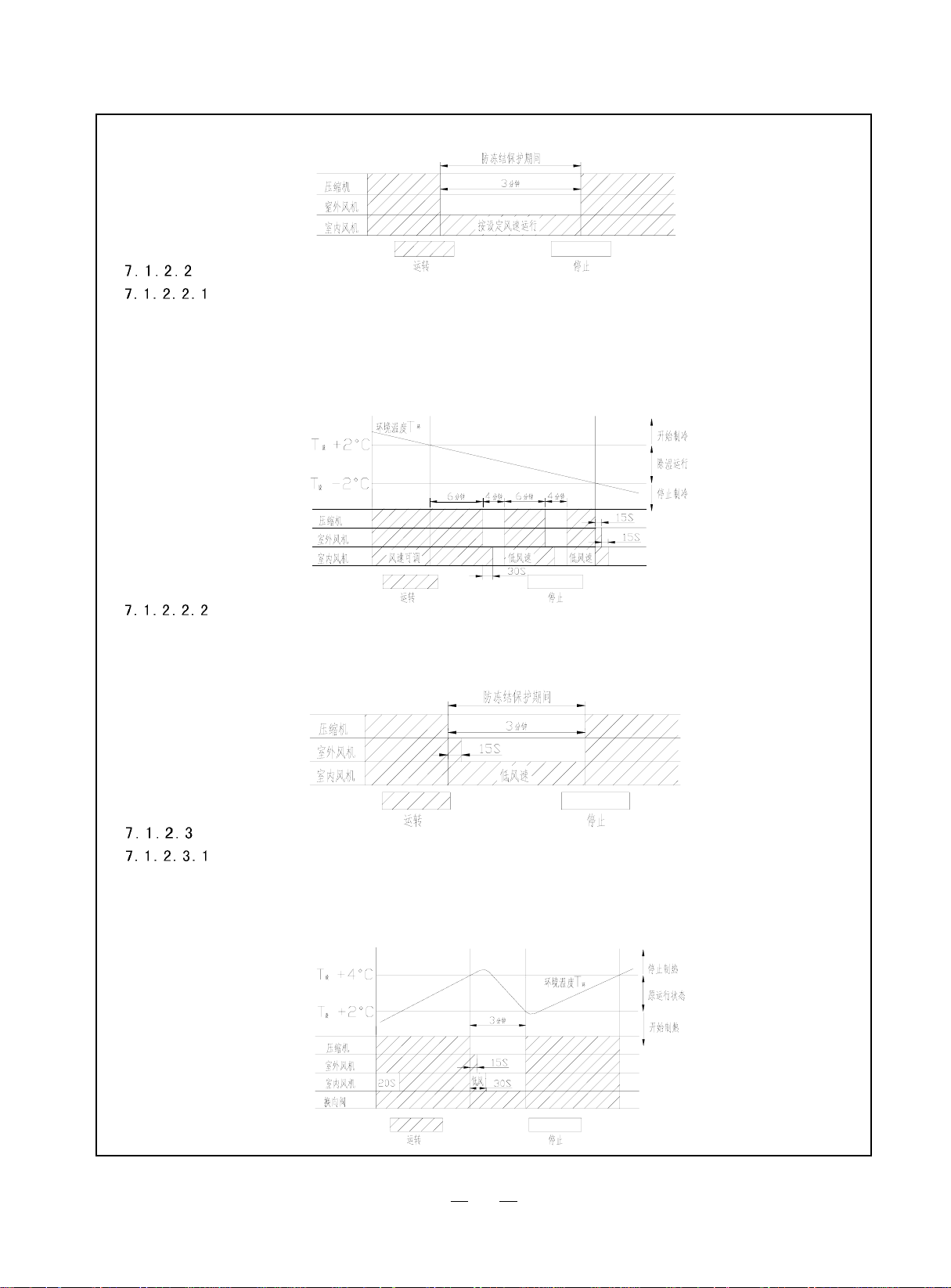
DRY Mode
The conditions and processes of dehumidifying:
If T
amb>Tset
If Tset -2℃≤Troom≤Tset+2℃,DRY mode will act, the indoor fan will run at the low speed.after running for 6mins, outdoor fan and compressor will stop, but
indoor fan will delay 30secs and stop, after 3.5mins, compressor and outdoor fan will run, and indoor fan will run at the low low speed. The processes of dehumidifying
a re shown as the above cycle.
If T
amb
+2℃, the cooling mode will act, indoor fan speed could be adjusted, outdoor fan will run.
< T
-2℃, the unit will stop, the compressor will stop, after 15sec latter, outdoor fan will stop, after another 15sec, indoor fan will stop.
set
In this mode, the reversal valve will not power on, the setting temp. range:16℃~30℃.
Protection Functions
Antifreezing Protection
When running in COOL mode, antifreezing protection is the same as the cooling. The DRY mode act, when the antifreezing protection is detected,
the compressor will stop, but outdoor fan will delay 15secs and stop, indoor fan will run at low speed; when antifreezing protection is eliminated and
compressor has stopped for 3min, the whole unit will run at the original status.
HEAT Mode
The conditions and processes of heating
If Tamb ≤Tset+2℃, HEAT mode will act, compressor, outdoor fan and reversing valve will run, but indoor fan will after 20sec delayed and run.
If Tamb≥Tset+4℃, Compressor will stop first, outdoor fan will delay 15s and stop, reversing valve will keep working, after 30secs indoor fan will blow
the surplus heat, after 30secs it will stop.
If Tset+2℃<T set<T set +4℃,the unit will keep running in the old mode.
In this mode, the reversal valve will not power on, the setting temp. range:16℃~30℃.
20
 Loading...