

Gree GRS-CQ16Pd/NaB-K, GRS-CQ14Pd/NaB-K, GRS-CQ14Pd/NaB-M, GRS-CQ12Pd/NaB-M, GRS-CQ12Pd/NaB-K Owner's Manual
...
Change for life
Thank you for choosing Commercial Air Conditioners ,please read this
owner’s manual carefully before operation and retain it for future reference.
Air-to-water Heat Pump
Commercial Air Conditioners
Owner's Manual

Contents
1 Instruction to Users..................................................................................1
2 Safety Considerations .............................................................................2
3 Diagram of the Operating Principle .........................................................4
4 Operating Principle of the Unit.................................................................4
5 Nomenclature ..........................................................................................6
6 Installation Example .............................................................................7
7 Main Components ..................................................................................9
7.1 Indoor unit .................................................................................................. 9
7.2 Outdoor unit ........................................................................................... 10
8 Installation Guideline of the Unit ............................................................ 11
8.1 Instruction to installation ...........................................................................11
8.2 Installation of outdoor unit ........................................................................11
9 Installation of Indoor Unit ....................................................................... 12
9.1 Select installation location of indoor unit ................................................ 12
9.2 Install process of indoor unit .................................................................... 13
9.3 Outline dimension of indoor unit ............................................................ 14
9.4 Space requirements for installation ......................................................... 15
9.5 Precautions on installation of indoor unit ................................................. 15
9.6 Water volume and pump capacity (with pump)........................................ 15
9.7 Water volume and expansion vessel pressure ........................................ 16
9.8 The method of calculating the charging pressure of expansion vessel ... 16
9.9 Selection of expansion vessel ................................................................. 17
10 Connection of Pipeline ........................................................................18
10.1 Connection of outlet pipe for indoor & outdoor unit .............................. 18
10.2 Installation of protective layer on connection pipe ................................ 18

11 Remote Air Temperature Sensor .........................................................20
12 Thermostat ..........................................................................................21
13 2-Ways Valve .......................................................................................21
14 3-Way Valve.........................................................................................22
15 Other Auxiliary Heat Sources .............................................................23
16 Gate-controller ................................................................................... 23
17 Filling of Refrigerant ............................................................................23
18 Installation of Insulated Water Tank .................................................... 24
18.1 Installation measure .............................................................................. 24
18.2 Outline dimension and parameter of water tank .................................... 25
18.3 Connection of waterway system ............................................................ 26
18.4 Electric wiring work ............................................................................... 27
19 Wring Diagram .....................................................................................29
19.1 PCB outline ............................................................................................ 29
19.2 Electric wiring work ................................................................................ 33
20 Debugging Operation of Unit .............................................................. 40
20.1 Check before startup ............................................................................. 40
20.2 Test run .................................................................................................. 41
21 Daily Operation and Maintenance ......................................................42
22 Operation Range .................................................................................44
Air-to-water Heat Pump
1
1 Instruction to Users
Thank you for choosing our Air to water Heat Pump. Please read this manual carefully before
installation and use the unit correctly according to the following procedure.
◆
After receipt of the unit, check it for appearance, unit model compared with your desire and
attachments.
◆
For proper installation and future maintenance please read this Instruction and keep it
carefully.
◆
Design and installation work of the unit must be performed by authorized personnel according
to applicable laws and regulations and this Instruction.
◆
After installation work, the unit can not be energized unless there is not any problem in check.
◆
Ensure periodical clean and maintenance of the unit after normal operation of the unit for
longer life and reliable operation.
◆
For improvement of products, there should be not additional notice of amendment of the
contents.
◆
This appliance is not intended for use by persons (including children) with reduced physical,
sensory or mental capabilities, or lack of experience and knowledge, unless they have been
given supervision or instruction concerning use of the appliance by a person responsible for
their safety.
◆
Children should be supervised to ensure that they do not play with the appliance.
Notice!
This product must not be disposed together with the domestic waste. This product has to be
disposed at an authorized place for recycling of electrical and electronic appliances.
Air-to-water Heat Pump
2
2 Safety Considerations
Please read the following contents carefully before operating.
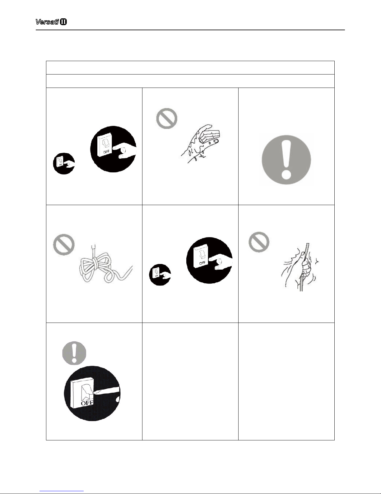
WARNING
■ Once abnormality like burning
smell occurs, please cut off
the power supply immediately
and then contact with service
center.
If the abnormality still exists, the
unit may be damaged and
electric shock or re may result.
■ Don't operate the unit with wet
hand.
Otherwise, it may cause electric
shock.
■ Before installation,please
see if the voltage of local
place accords with that on
nameplate of unit and capacity
of power supply, power cord
or socket is suitable for input
power of this unit.
■ Special circuit must be
adopted for power supply to
prevent re.
Do not use octopus multipurpose
plug or mobile terminal board for
wire connection.
■ Be sure to pull out the power
plug and drain the indoor unit
and water tank when unit is
not in use for a long time.
Otherwise, the accumulated dust
may cause overheating,fire or
freeze of water tank or coaxial
heater exchanger in winter.
■ Never damage the electric
wire or use the one which is
not specied.
Otherwise, it may cause
overheating or re.
■ Before cleaning please cut off
the power supply.
Otherwise, it may cause electric
shock or damage.
■ The power supply must adopt
special circuit with leakage
switch and enough capacity.
■ User can not change power
cord socket without prior
consent. Wiring working must
be done by professionals.
Ensure good earthing and
don't change earthing mode
of unit.
Air-to-water Heat Pump
3
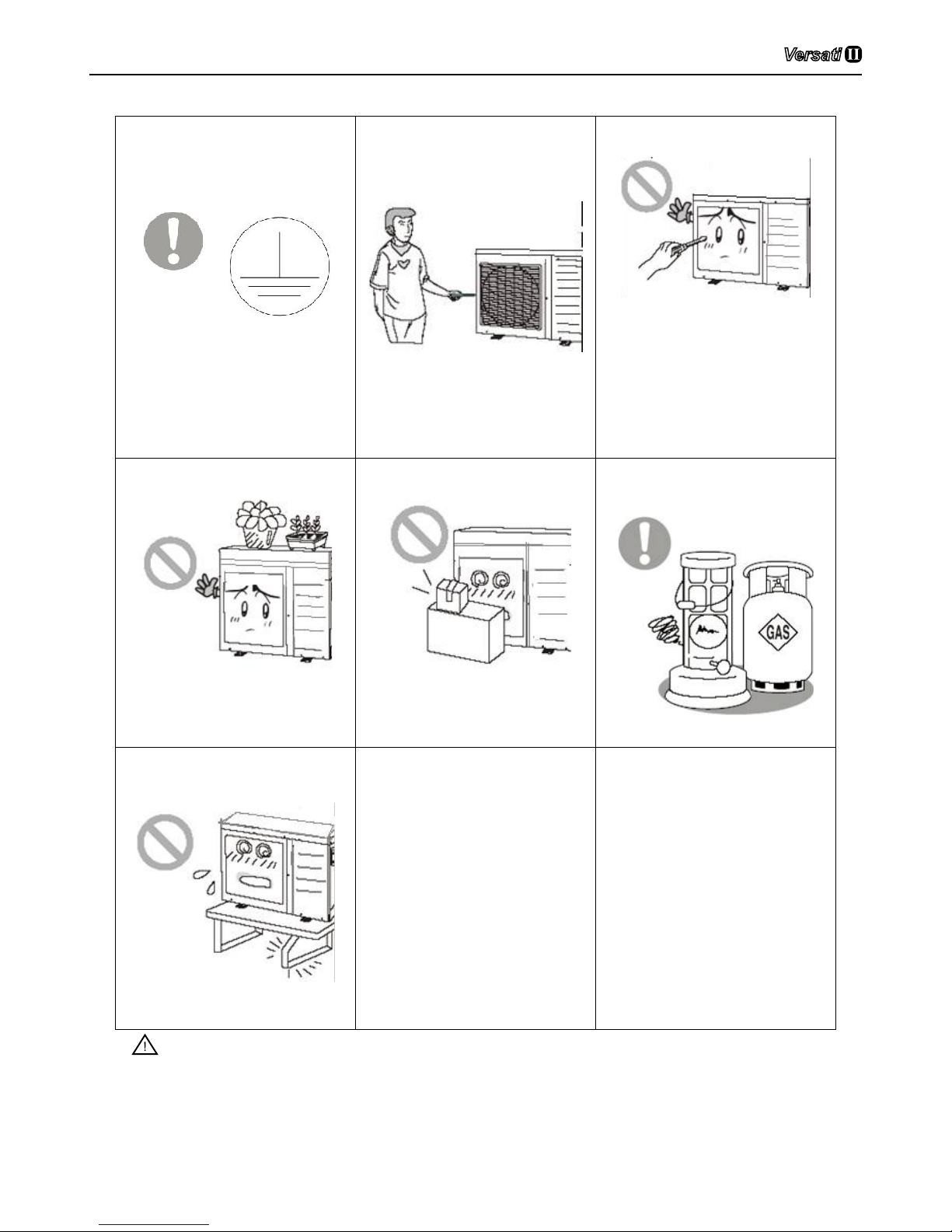
■ Earthing: the unit must be
earthed reliably ! The earthing
wire should connect with
special device of buildings.
If not, please ask the qualified
personnel to install.
Furthermore, don't connect
earth wire to gas pipe, water
pipe, drainage pipe or any
other improper places which
professional does not recognize.
■ Never insert any foreign
matter into uint to avoid
damage . And never insert
your hands into the air outlet
of outdoor unit.
■ Don't attempt to repair the unit
by yourself.
Improper repair may cause electric
shock or fire, so you should
contact the service center to
repair.
■ Don't step on the top of the
unit or place anything on it.
There is the danger of fall of
things or people.
■ Never block the air inlet and
outlet of unit.
It may reduce efficiency or cause
stop of the unit and even re.
■ Keep pressurized spray, gas
holder and so on away from
the unit above 1m .
It may cause re or explosion.
■ Please note whether the
installation stand is firm
enough or not.
If damaged, it may cause fall of
the unit and injury of people.
■ Unit should be installed at the
place with good ventilation to
save energy.
■ When there is not water in
water tank, never power the
unit on to run.
Notice!
(1) Before installation, please check if the adopted power is accordance with that listed on
nameplate, and check the safety of power.
(2) Before using, please check and conrm if wires and water pipes are connected correctly to
avid water leakage, electric shock or re etc.
Air-to-water Heat Pump
4
(3) Don’t operate the unit with wet hand, and don’t allow children to operate the unit.
(4) The On/off in the instruction is for the operation to on and off button of PCB for users; cut off
power means to stop supplying power to the unit.
(5) Don’t directly expose the unit under the corrosive ambient with water or dampness.
(6) Don’t operate the unit without water in water tank .The air outlet/inlet of unit can not be
blocked by other objects.
(7) The water in unit and pipeline should be discharged if the unit is not in use, to prevent the
water tank, pipe line and water pump from frost-cracking.
(8) Never press the button with sharp objects to protect manual controller. Never use other wires
instead of special communication line of the unit to protect control elements. Never clean
the manual controller with benzene, thinner or chemical cloth to avoid fading of surface and
failure of elements. Clean the unit with the cloth soaked in neutral eradicator .Slightly clean
the display screen and connecting parts to avoid fading.
(9) The power cord must be separated with the communication line.
If there is any question, please contact with local dealer, authorized service center, agencies
or our company directly.
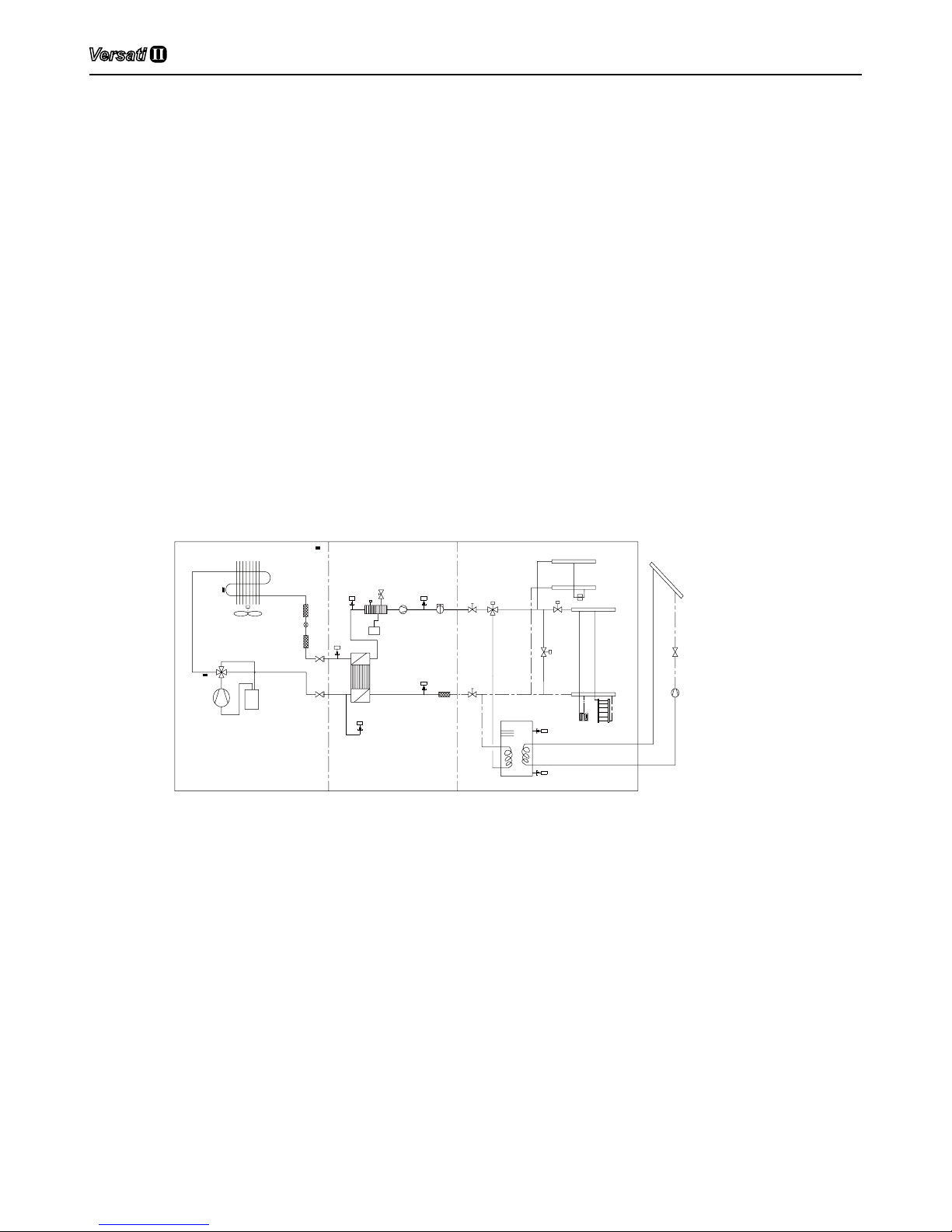
3 Diagram of the Operating Principle
R3T gas line temperature sensor
17
15
16
INDOOR UINTOUTDOOR UINT
M
M
M
M
1
2
3
4
5
6
7
8
10
11
20
19
5
18
12
1 compressor
2 four-way valve
3 finned coil exchanger
4 fan motor
5 filter
6 electronic expansion valve
7 plate heat exchanger
11 flow switch
10 electric heater
9 air-vent valve
8 pump
18 water tank
12 3-way valve
17 other thermal system
16 radiator
15 under-floor heating
R6T water tank temperature sensor 1
R4T returning water temperature sensor
R1T plate outlet temperature sensor
t
R1T
R3T
t
R5T
t
R4T
t
t
R6T
t
R2T
9
19 expansion tank
20 safety valve
R2T Liquid line temperature sensor
R5T leaving water temperature sensor
t
R7T
R7T water tank temperature sensor 2
13
14
13 2-way valve
14 by-pass valve
4 Operating Principle of the Unit
DC Inverter Air to Water Heat Pump is composed of outdoor unit, indoor unit and internal-fan coil
water tank. Operation functions:
(1) Cooling;
(2) Heating;
(3) Water heating;
(4) Cooling +water heating;
(5) Heating+ water heating;

Air-to-water Heat Pump
5
(6) Emergency mode;
(7) Quick water heating;
(8) Holiday mode;
(9) Forced Operation Mode;
(10) Silent mode;
(11) Disinfection mode;
(12) Weather-dependent Operation;
(13) Floor debugging
(14) Air removal of the water system
Cooling: in cooling mode, the refrigerant is condensed in the outdoor unit and evaporated in the
indoor unit. Via the heat exchange with water in the indoor unit, the temperature of water decrease
and it releases heat while the refrigerant absorbs heat and evaporates. With the help of wired
controller, the outow temperature can meet the user’s requirement. Through the control of valve,
the low-temperature water in the system is connected with indoor fan coil and underground pipe, and
exchanges heat with the indoor air so that the indoor temperature decreases to the required range.
Heating: in heating mode,the refrigerant evaporates in the outdoor unit and is condensed in
the indoor unit. Via the heat exchange with water in the indoor unit, the water absorbs heat and its
temperature increase while the refrigerant releases heat and is condensed. With the help of wired
controller, the outow temperature can meet the user’s requirement. Through the control of valve, the
high-temperature water in the system is connected with indoor fan coil and underground pipe, and
exchanges heat with the indoor air so that the indoor temperature increases to the required range.
Water heating: in water heating mode: the refrigerant evaporates in the outdoor unit and is
condensed in the indoor unit. Via the heat exchange with water in the indoor unit, the water absorbs
heat and its temperature increase while the refrigerant releases heat and is condensed. With the help
of wired controller, the outow temperature can meet the user’s requirement. Through the control of
valve, the high-temperature water in the system is connected with the coil pipe of bearing water tank,
and exchanges heat with the water in the water tank so that the temperature of water tank increases
to the required range.
Cooling + water heating: when cooling mode exists together with the water heating mode, the
user can set the priority of these two modes based on the needs. The default priority is heat pump.
That is under the default setting, if cooling mode exists together with the water heating mode, the
heat pump gives priority to cooling. In that case, water heating can only realized with e-heater of
the water tank. Inversely, the heat pump gives priority to water heating and switches to cooling after
nishing water heating.
Heating+ water heating: when heating mode exists together with the water heating mode, the
user can set the priority of these two modes based on the needs. The default priority is heat pump.
That is under the default setting, if heating mode exists together with the water heating mode, the
heat pump gives priority to heating. In that case, water heating can only realized with e-heater of
the water tank. Inversely, the heat pump gives priority to water heating and switches to heating after
nishing water heating.
Emergency mode: this mode is only available for heating and water heating. When the outdoor
unit stops due to malfunction, enter the corresponding emergency mode; as to heating mode, after
entering the emergency mode, heating can only be realized through e-heater of the indoor unit. When
the setting outow temperature or indoor temperature is reached, the e-heater of indoor unit will stop
running; as to water heating mode, the e-heater of indoor unit stops while the e-heater of water tank
runs. When the setting temperature or water tank is reached, the e-heater will stop running.
Quick water heating: in quick water heating mode, the unit runs according to the water heating
Air-to-water Heat Pump
6
control of heat pump and the e-heater of water tank runs at the same time.
Forced Operation Mode: this mode is only used for refrigerant recovery and debugging for the
unit.
Holiday mode: this mode is only available for heating mode. This mode is set to keep indoor
temperature or leaving water temperature in a certain range, so as to prevent water system of the unit
from freezing or protect certain indoor articles from freezing damage. When the outdoor unit stops
due to malfunction, the two e-heaters of the unit will run.
Disinfection mode: in this mode, the water heating system can be disinfected. When starting up
the disinfection function and setting corresponding time to meet the requirement of disinfection mode,
the function will start. After the setting temperature is reached, this mode will terminate.
Weather-dependent Operation: this mode is only available for space heating. In Weatherdependent mode, the setting value (remote room air temperature or leaving water temperature) is
detected and controlled automatically when the outdoor air temperature is changed.
Silent mode: Silent mode is available in cooling, heating and water heating mode. In silent mode,
the outdoor unit will reduce the running noise via automatic control.
Floor commissioning: this function is intended to preheat the oor periodically for the initial use.
Air removal of the water system: this function is intended to replenish water and remove air in
the water system to make the equipment run at the stabilized water pressure.
5 Nomenclature
G RS - C Q 16 Pd / Na B - K (O)
1 2 3 4 5 6 7 8 9 10
NO. Description Options
1 GREE G-GREE Air to water heat pump
2 Heat Pump Water Heater RS
3 Heating Mode S= Static; C=Circulating
4 Function Q=Multi-function; Omit=Single-function
5 Nominal Heating Capacity 6=6.0kW; 8=8.0kW;10=10kW; 12=12kW; 14=14kW; 16=16kW
6 Compressor Style Pd=DC Inverter; Omit=On/Off
7 Refrigerant Na=R410A
8 Design Serial Number B,C,D......
9 Power Supply K=220-240V,~,50Hz; M=380-415V,3N~,50Hz; H=380V,3N~,60Hz
10 Indoor and Outdoor Unit Code I=Indoor unit; O=Outdoor unit
Model Line-Up
Model Name
Capacity
Power supply
Heating
1
,kW Cooling2,kW
GRS-CQ16Pd/NaB-K 15.5 14.5
220-240V,~,50HzGRS-CQ14Pd/NaB-K 13.5 13.5
GRS-CQ12Pd/NaB-K 12.5 12.5
GRS-CQ16Pd/NaB-M 15.5 15.0
380-415V,3N~,50HzGRS-CQ14Pd/NaB-M 14.2 14.5
GRS-CQ12Pd/NaB-M 12.5 13.5
Note:
1
Capacities and power inputs are based on the following conditions:
Indoor Water Temperature 30°C/35°C,Outdoor Air Temperature 7°C DB/6°C WB;
2
Capacities and power inputs are based on the following conditions:
Indoor Water Temperature 23°C/18°C,Outdoor Air Temperature 35°C DB/24°C WB.
Air-to-water Heat Pump
7
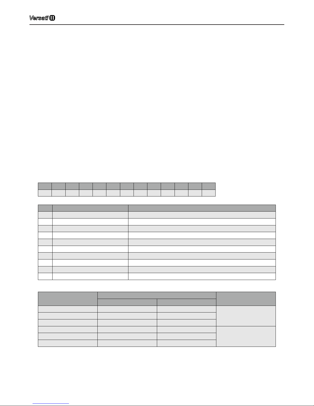
6 Installation Example
CASE 1: Connecting Under-oor Coil for Heating and Cooling
B
Under- floo r coil
Outdoo r
Indoor
T
Shut o ff value
By-pass value(Field supply)
Remote room Thermo stat(Field supply)
High temperature line
Low temperature line
T
B
Note:
①
Type of thermostat and specication should be complied with installation of this manual;
②
By pass valve must be installed to secure enough water ow rate,and by pass valve should be
installed at the collector;
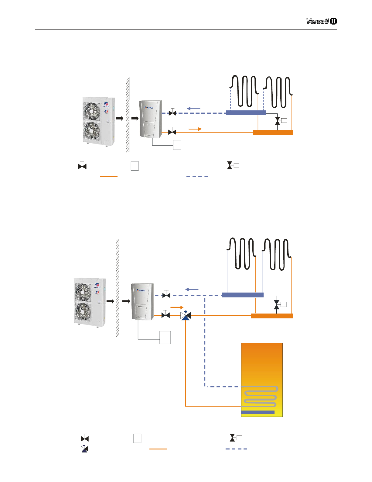
CASE 2: Connecting Sanitary Water Tank
Shut off value
By-pass value(Field supply)
Remote room Thermo stat(Field suppl y)
High temperature line
Low temperature line
T
B
3-way value(Field supply)
B
T
IndoorOutdoor
Booster heater
Sanitary water tank
Under-floor coil
Air-to-water Heat Pump
8
Note:
①
In this case, three-way valve should be installed and should be complied with installation of this
manual;
②
Sanitary water tank should be equipped with internal electric heater to to secure enough heat
energy in the very cold days;
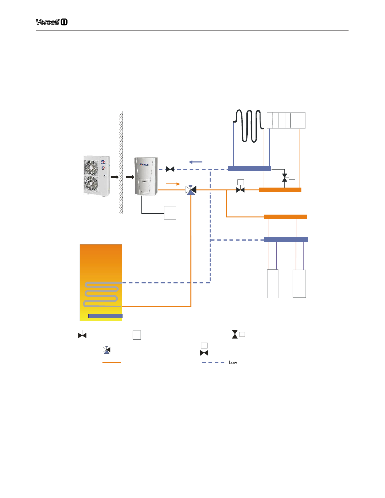
CASE 3 : Connecting Sanitary Water Tank and Heat Emitters for Heating and Cooling
IndoorOutdoor
Booster heater
Sanitary water tank
Under-floor coil Radiator
Shut off value
By-pass value(Field supply)
Remote room Thermo stat(Field suppl y)
High tempe rature temperature line
line
T
B
3-way value (Field supply)
B
FCU 1
FCU2
M
T
M
2-way value(Field supply)
Two-way valve is very important to prevent dew condensation on the floor and Radiator while
cooling mode.

Air-to-water Heat Pump
9
7 Main Components
7.1 Indoor unit
GRS-CQ12Pd/NaB-K(I), GRS-CQ14Pd/NaB-K(I), GRS-CQ16Pd/NaB-K(I), GRS-CQ12Pd/NaB-M(I),
GRS-CQ14Pd/NaB-M(I), GRS-CQ16Pd/NaB-M(I)
External
Air Vent
Electric Heater
Plate Heat Exchanger
Control Box
Control Panel
Water Pressure Gage
Flow Switch
Water Pum
p
Expansion Tank
Safety Valve
Internal
Air-to-water Heat Pump
10
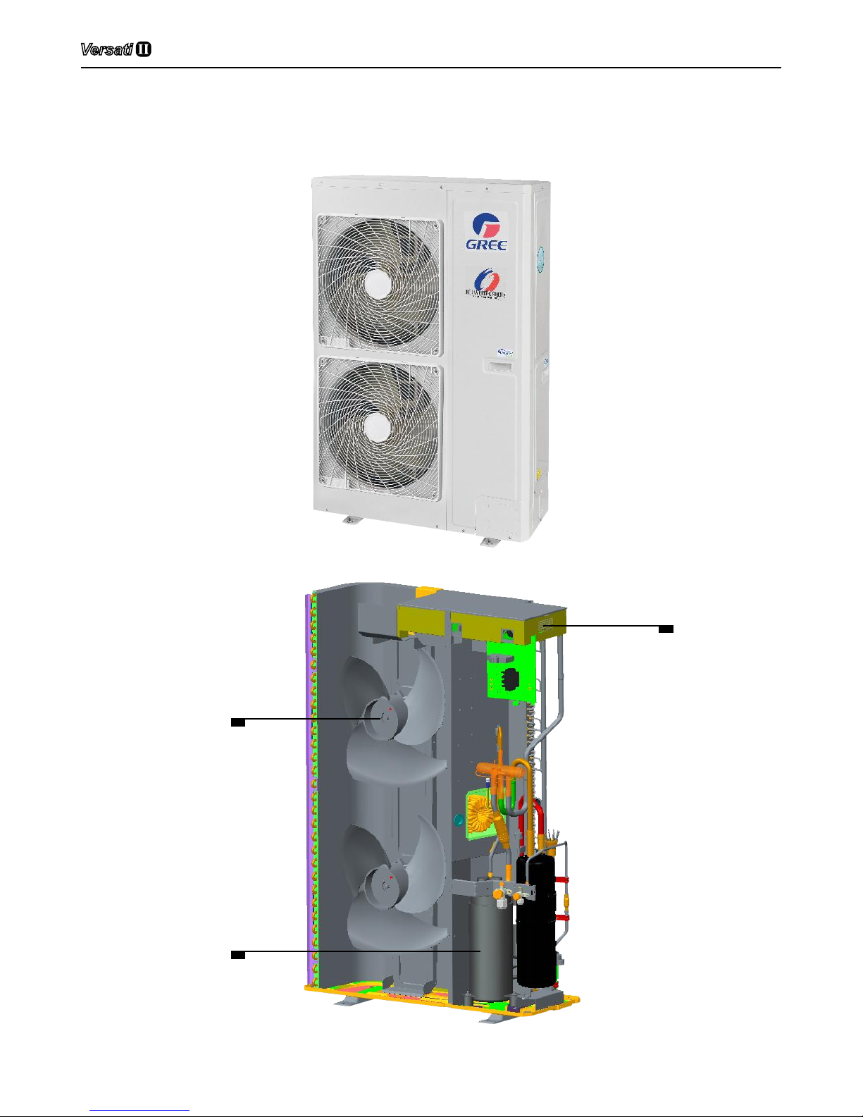
7.2 Outdoor unit
GRS-CQ12Pd/NaB-K(O), GRS-CQ14Pd/NaB-K(O), GRS-CQ16Pd/NaB-K(O), GRS-CQ12Pd/NaB-M(O),
GRS-CQ14Pd/NaB-M(O), GRS-CQ16Pd/NaB-M(O)
External
Compressor
Control Box
DC Fan Motor
Internal
Air-to-water Heat Pump
11
8 Installation Guideline of the Unit
8.1 Instruction to installation
(1) The installation of unit must be in accordance with national and local safety codes.
(2) Installation quality will directly affect the normal use of air conditioner unit. The user is
prohibited from installation by himself. Please contact your dealer after buying this machine.
Professional installation workers will provide installation and test services according to
installation manual.
(3) Do not connect to power until all installation work is completed.
8.2 Installation of outdoor unit
8.2.1 Select installation location of outdoor unit
(1) Outdoor unit must be installed on a rm and solid support.
(2) Outdoor unit shall be installed close to the indoor unit, hence to minimize the length and
bends of cooling pipe.
(3) Avoid placing the outdoor unit under window or between two constructions, hence to prevent
normal operating noise from entering the room.
(4) Air ow at inlet and outlet shall not be blocked.
(5) Install at a well-ventilated place, so that the machine can absorb and discharge sufcient air.
(6) Do not install at a place where flammable or explosive goods exist or a place subject to
severe dust, salty fog and polluted air.
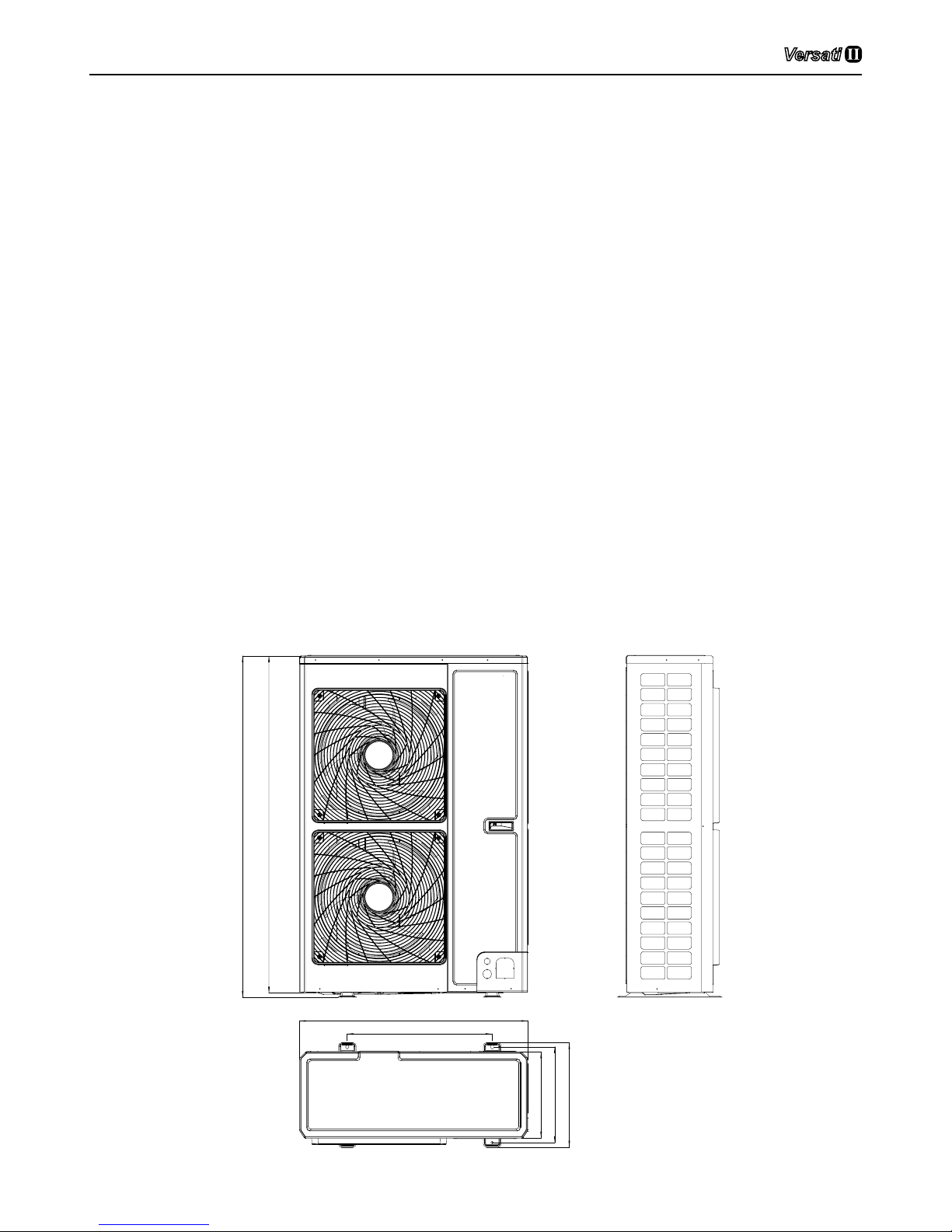
8.2.2 Outline dimension of outdoor unit
GRS-CQ12Pd/NaB-K(O), GRS-CQ14Pd/NaB-K(O), GRS-CQ16Pd/NaB-K(O),GRS-CQ12Pd/NaBM(O), GRS-CQ14Pd/NaB-M(O), GRS-CQ16Pd/NaB-M(O)
900
572
412
378
1345
1326
340
Air-to-water Heat Pump
12
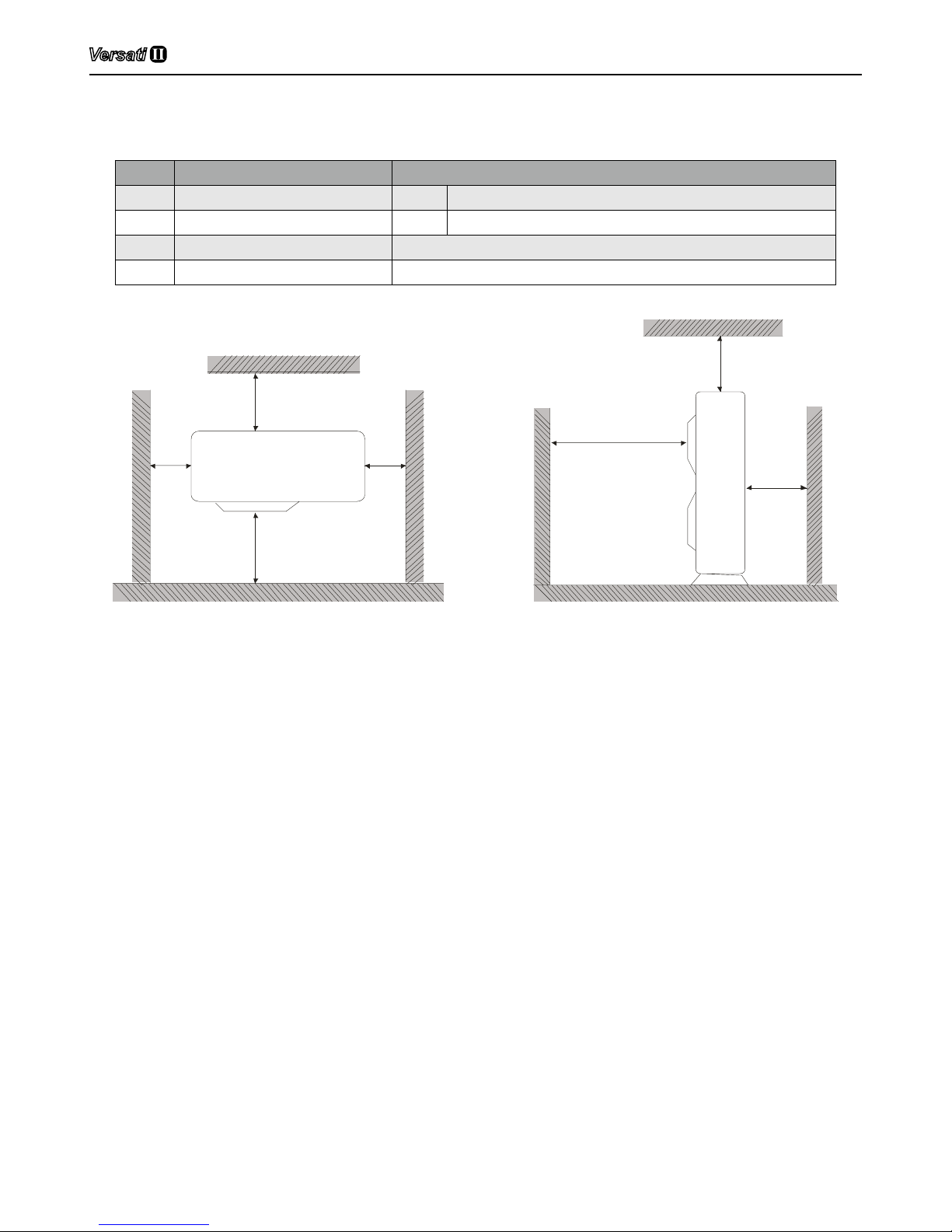
Description:
Unit: inch
No Name Remarks
1 Liquid-side Service Valve 3/8 GRS-CQ12/14/16Pd/NaB-K,GRS-CQ12/14/16Pd/NaB-M
2 Gas-side Service Valve 5/8 GRS-CQ12/14/16Pd/NaB-K,GRS-CQ12/14/16Pd/NaB-M
3 Handle Used to cover or uncover the front case
4 Air discharge Grill /
8.2.2 Space requirements for installation
>1000
>
2000
>
500
>
500
>
500
>
500
>
2000
8.2.3 Precautions on installation of outdoor unit
(1) When moving outdoor unit, it is necessary to adopt 2 pieces of long enough rope to hand the
unit from 4 directions. Included angle between the rope when hanging and moving must be
40°below to prevent center of the unit from moving.
(2) Adopt M12 bolts components to tighten feet and under frame when installing.
(3) Outdoor unit should be installed on concrete base that is 10cm height.
(4) Requirements on installation space dimension of unit’s bodies are shown in following
drawing.
(5) Outdoor unit must be lifted by using designated lifting hole. Take care to protect the unit
during lift. To avoid rusting, do not knock the metal parts.
9 Installation of Indoor Unit
9.1 Select installation location of indoor unit
(1) Avoid direct sunshine.
(2) Ensure the hanger rod, ceiling and building structure have sufcient strength to support the
weight of air conditioner unit.
(3) Drainage pipe is easy to connect out.
(4) Indoor and outdoor connection pipes are easy to go outdoors
(5) Do not install at a place where ammable or explosive goods exist or ammable or explosive
gas might leak.
(6) Do not install at a place subject to corrosive gas, severe dust, salty fog, smoke or heavy
moisture.
(7) Air ow at inlet and outlet air is not blocked.
 Loading...