

GREE GRS-CQ16Pd/NaE-M, GRS-CQ12Pd/NaE-M, GRS-CQ10Pd/NaE-K, GRS-CQ14Pd/NaE-M, GRS-CQ12Pd/NaE-K Owner's Manual
...
Change for life
Air-to-water Heat Pump Split Versati
Models:
GRS-CQ8.0Pd/NaE-K GRS-CQ10Pd/NaE-K
GRS-CQ12Pd/NaE-K GRS-CQ14Pd/NaE-K
GRS-CQ16Pd/NaE-K GRS-CQ12Pd/NaE-M
GRS-CQ14Pd/NaE-M GRS-CQ16Pd/NaE-M
Owner's Manual
Original Instructions
Air Conditioners
SPLIT
TYPE
Thank you for choosing GREE air conditioners. Please read this
Owner’s Manual carefully before operation and retain it for future
reference.
If
you have lost the Owner's Manual,please contact the local agent
o
r visit www.gree.com or send an email to global@gree.com.cn for
t
he electronic version.
GREE ELECTRIC APPLIANCES, INC. OF ZHUHAI

To Users
Thank you for selecting Gree’s product. Please read this instruction manual carefully before installing and using
the product, so as to master and correctly use the product. In order to guide you to correctly install and use our
product and achieve expected operating effect, we hereby instruct as below:
(1) This equipment should be installed, operated or maintained by the qualified servicemen who have had
specific training. During operation, all safety issues covered in the labels, User’s Manual and other
literature should be followed strictly. This appliance can be used by children aged from 8 years and above
and persons with reduced physical, sensory or mental capabilities or lack of experience and knowledge
if they have been given supervision or instruction concerning used of this appliance in a safety way
and understand the hazards involved. Children shall not play with the appliances. Cleaning and user
maintenance shall not be made by children without supervision.
(2) This product has gone through strict inspection and operational test before leaving the factory. In order to
avoid damage due to improper disassembly and inspection, which may impact the normal operation of unit,
please do not disassemble the unit by yourself. You can contact with the special maintenance center of our
company if necessary.
(3) For personal injury or property loss and damage caused by improper operation such as improper
installation and debugging, unnecessary maintenance, violation of related national laws and rules and
industrial standard, and violation of this instruction manual, etc., we will bear no liability.
(4) When the product is faulted and cannot be operated, please contact with our maintenance center as soon
as possible by providing the following information.
•
Contents of nameplate of product (model, cooling/heating capacity, product No., ex-factory date).
•
Malfunction status (specify the situations before and after the error occurs).
(5) All the illustrations and information in the instruction manual are only for reference. In order to make the
product better, we will continuously conduct improvement and innovation. We have the right to make
necessary revision to the product from time to time due to the reason of sales or production, and reserve
the right to revise the contents without further notice.
(6) The nal right to interpret for this instruction manual belongs to Gree Electric Appliances Inc. of Zhuhai.

Contents
Safety Notices (Please be sure to abide ) ...................................................................1
1. Diagram of the Operating Principle .........................................................................7
2. Operating Principle of the Unit .................................................................................8
3. Nomenclature...........................................................................................................10
4. Installation Example ............................................................................................. 11
5. Main Components ..................................................................................................14
5.1 Indoor unit .......................................................................................................................14
5.2 Outdoor unit ..................................................................................................................16
6. Installation Guideline of Outdoor Unit ...................................................................19
6.1 Instruction to installation .................................................................................................19
6.2 Installation of outdoor unit ...............................................................................................19
7. Installation of Indoor Unit ....................................................................................... 21
7.1 Select installation location of indoor unit ........................................................................21
7.2 Install process of indoor unit ...........................................................................................22
7.3 Outline dimension of indoor unit ...................................................................................24
7.4 Space requirements for installation .................................................................................24
7.5 Precautions on installation of indoor unit ........................................................................25
7.6 Water volume and pump capacity (with pump) ...............................................................25
7.7 Water volume and expansion vessel pressure ...............................................................25
7.8 Selection of expansion vessel .........................................................................................26
8. Connection of Pipeline ...........................................................................................27
8.1 Connection of outlet pipe for indoor & outdoor unit ........................................................27
8.2 Installation of protective layer on connection pipe .........................................................27
9. Remote Air Temperature Sensor ............................................................................ 29
10. Thermostat ............................................................................................................. 30
11. 2-Way Valve ............................................................................................................ 31
12. 3-Way Valve ............................................................................................................ 32
13. Other Auxiliary Heat Sources ............................................................................. 32
14. Gate-controller ....................................................................................................... 32
15. Charging and Discharging of Refrigerant ........................................................... 33
16. Refrigerant Collecting ........................................................................................... 34
17. Handling of the Unit ..............................................................................................35
18. Installation of Insulated Water Tank ...................................................................36
18.1 Installation measure ......................................................................................................36
18.2 Outline dimension and parameter of water tank ...........................................................37

18.3 Connection of waterway system ...................................................................................38
18.4 Electric wiring work ......................................................................................................39
19. Wring Diagram ....................................................................................................... 41
19.1 Control Board ................................................................................................................41
19.2 Electric Wiring ...............................................................................................................49
20. Commissioning......................................................................................................53
20.1 Check before startup .....................................................................................................53
20.2 Test run .........................................................................................................................54
21. Daily Operation and Maintenance ....................................................................... 55
Air-to-water Heat Pump Split Versati
1
Safety Notices (Please be sure to abide )
WARNING
:
If not abide strictly, it may cause severe damage to the unit or the
people.
NOTE
: If not abide strictly, it may cause slight or medium damage to the unit or the
people.
This sign indicates that the operation must be prohibited. Improper operation may
cause severe damage or death to people
This sign indicates that the items must be observed. Improper operation may
cause damage to people or property.
NOTE
After receipt of the unit, check it for appearance, unit model compared with your desire
and attachments.
Design and installation work of the unit must be performed by authorized personnel
according to applicable laws and regulations and this Instruction.
After installation work, the unit cannot be energized unless there is not any problem in
check.
Ensure periodical clean and maintenance of the unit after normal operation of the unit
for longer life and reliable operation.
If the supply cord is damaged, it must be replaced by the manufacturer, its service
agent or similarly qualied persons in order to avoid a hazard.
The appliance shall be installed in accordance with national wiring regulations.
This product is a kind of comfort air conditioning, and is not allowed to be installed
where there are corrosive, explosive and inammable substances or smog; otherwise
it would lead to operation failure, shortened service life, five hazard or even severe
injuries. Special air conditions are required for where mentioned above.
Correct Disposure
This marking indicates that this product should not be
disposed with other household wastes throughout the EU.To
prevent possible harm to the environment or human health from
uncontrolled waste disposal,recycle it responsibly to promote the
sustainable reuse of material resources. To retuern your used
device,please use the return and collection systems or contact
the retailer where the product was purchased. They can take this
product for environmental safe recycling.
R410A(R32/125:50/50):2087.5
Air-to-water Heat Pump Split Versati
2
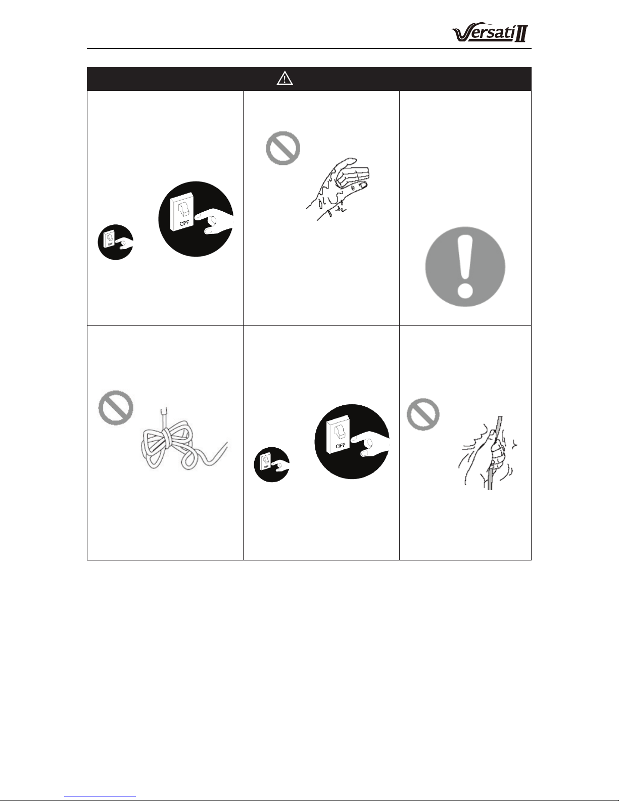
WARNING
Once abnormality
likeburning smell occurs,
please cut off the power
supply immediately and
then contact with service
center.
If the abnormality still exists,
the unit may be damaged
and electric shock or re
may result.
Don't operate the unit with
wet hand.
Otherwise, it may cause
electric shock.
Before
installation,please see
if the voltage of local
place accords with
that on nameplate
of unit and capacity
of power supply,
power cord or socket
is suitable for input
power of this unit.
Special circuit must be
adopted for power supply
to prevent re.
Do not use octopus
multipurpose plug or mobile
terminal board for wire
connection.
Be sure to pull out the
power plug and drain the
indoor unit and water tank
when unit is not in use for a
long time.
Otherwise, the accumulated
dust may cause
overheating,re or freeze of
water tank or coaxial heater
exchanger in winter.
Never damage the
electric wire or use
the one which is not
specied.
Otherwise, it may
cause overheating or
re.
Air-to-water Heat Pump Split Versati
3
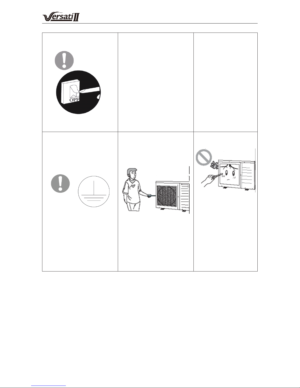
Before cleaning please cut
off the power supply.
Otherwise, it may cause
electric shock or damage.
The power supply must
adopt special circuit with
leakage switch and enough
capacity.
User can not change
power cord socket
without prior consent.
Wiring working
must be done by
professionals. Ensure
good earthing and
don't change earthing
mode of unit.
Earthing: the unit must
be earthed reliably ! The
earthing wire should
connect with special device
of buildings.
If not, please ask the
qualied personnel to
install.
Furthermore, don't connect
earth wire to gas pipe,
water pipe, drainage pipe or
any other improper places
which professional does not
recognize.
Never insert any foreign
matter into outdoor unit to
avoid damage . And never
insert your hands into the
air outlet of outdoor unit.
Don't attempt to repair
the unit by yourself.
Improper repair may
cause electric shock
or re, so you should
contact the service
center to repair.

Air-to-water Heat Pump Split Versati
4
Don't step on the top of the
unit or place anything on it.
There is the danger of fall of
things or people.
Never block the air inlet and
outlet of unit.
It may reduce efciency or
cause stop of the unit and
even re.
Keep pressurized
spray, gas holder and
so on away from the
unit above 1m .
It may cause re or
explosion.
Please note whether the
installation stand is rm
enough or not.
If damaged, it may cause
fall of the unit and injury of
people.
Unit should be installed
at the place with good
ventilation to save energy.
When there is not
water in water tank,
never power the unit
on to run.

Air-to-water Heat Pump Split Versati
5
NOTE
Before installation, please check if the adopted power is accordance with that listed on
nameplate, and check the safety of power.
An all-pole disconnection switch having a contact separation of at least 3mm in all
poles should be connected in xed wiring.
Before using, please check and confirm if wires and water pipes are connected
correctly to avoid water leakage, electric shock or re etc.
Don’t operate the unit with wet hand, and don’t allow children to operate the unit.
The On/off in the instruction is for the operation to on and off button of PCB for users;
cut off power means to stop supplying power to the unit.
Don’t directly expose the unit under the corrosive ambient with water or dampness.
Don’t operate the unit without water in water tank .The air outlet/inlet of unit cannot be
blocked by other objects.
The water in unit and pipeline should be discharged if the unit is not in use, to prevent
the water tank, pipe line and water pump from frost-cracking.
Never press the button with sharp objects to protect manual controller. Never use
other wires instead of special communication line of the unit to protect control elements.
Never clean the manual controller with benzene, thinner or chemical cloth to avoid
fading of surface and failure of elements. Clean the unit with the cloth soaked in neutral
eradicator. Slightly clean the display screen and connecting parts to avoid fading.
The power cord must be separated with the communication line.
Air-to-water Heat Pump Split Versati
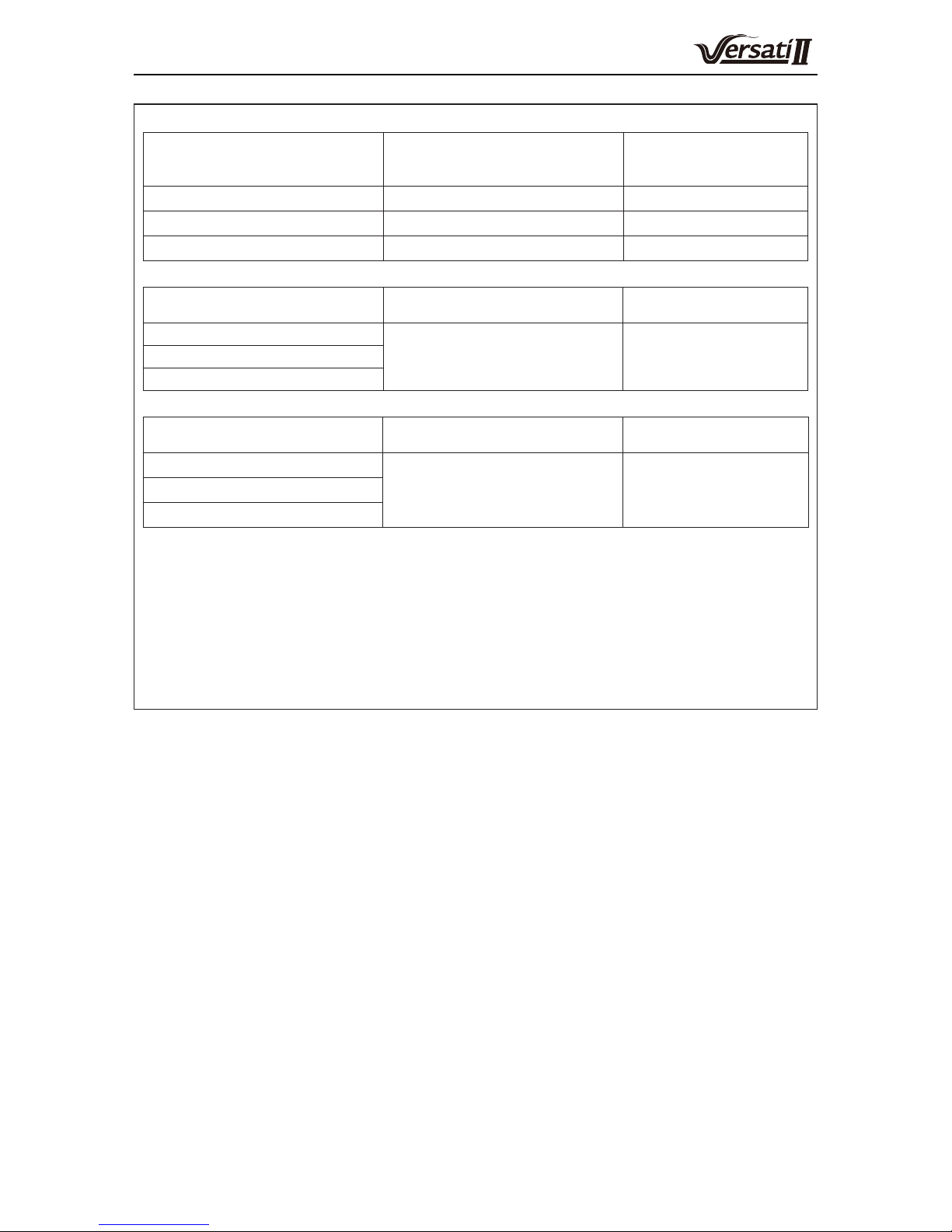
6
maximum and minimum water operating temperatures.
Item
Minimum water operating
temperatures
Maximum
water operating
temperatures
Cooling 7°C 25°C
Heating 25°C 55°C
Water heating 40°C 80°C
maximum and minimum water operating pressures.
Item
Minimum water operating
pressures
Maximum water
operating pressures
Cooling
0.05MPa 0.25MPaHeating
Water heating
maximum and minimum entering water pressures.
Item
Minimum entering water
pressures
Maximum entering
water pressures
Cooling
0.05MPa 0.25MPa Heating
Water heating
The range of external static pressures at which the appliance was tested (add-on
heat pumps, and appliances with supplementary heaters, only); If the supply cord
is damaged, it must be replaced by the manufacturer, its service agent or similarly
qualied persons in order to avoid a hazard.
The appliance is intended to be permanently connected to the water mains and not
connected by a hose-set.
If there is any question, please contact with local dealer, authorized service center,
agencies or our company directly.
Air-to-water Heat Pump Split Versati
7
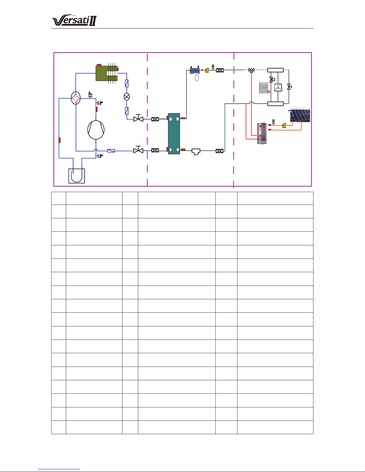
1. Diagram of the Operating Principle
1
2
3
4
5
6
7
8
9
10
17
16
21
24
26
27
28
29
30
22
23
25
15
20
Outdoor Unit
31
32
Indoor Unit
12
13
D
C
E
S
18
19
14
Field Supplied
35
33
34
36
37
38
3940
41
42
43
44
45
46
47
11
48
49
50
No. Name No. Name No. Name
1 Compressor 18
Liquid Temperature
Sensor of the PHE
35 Water Tank
2
Discharge Temperature
Sensor
19
Gas Temperature Sensor of the
PHE
36
Leaving Water Temperature
Sensor of the Solar System
3 High Pressure Switch 20 Plate-type Exchanger 37
Flow Switch for the Solar
System
4 Pressure Sensor 21
Leaving Water Temperature
of the PHE
38
Water Pump for the Solar
System
5 4-way Valve 22
Entering Water Temperature
of the PHE
39 Solar Panel
6 Finned Exchanger 23 Automatic Exhaust Valve 40 Solar Panel Temperature Sensor
7
Environment
Temperature Sensor
24 Electric Heater 41
Entering Water Temperature
for the Solar System
8
Defrosting Temperature
Sensor
25 Safety Valve 42 Water Knockout Vessel
9 Filter 26 Expansion Tank 43 Electric 2-way Valve 1
10
Electrostatic Expansion
Valve
27
Leaving Water Temperature
of the Electric Heate
44 Floor Radiator
11 Filter 28 Water Pump 45 Water Collector
12 Liquid Valve 29 Flow Switch 46 FCU
13 Gas Valve 30
Leaving Water Pipe
Connector
47
Pressure Differential Bypass
Valve
14 Filter 31
Entering Water Pipe
Connector
48
Water Tank Temperature
Sensor 2
15 Vapor-liquid Separator 32 Water Filter 49 Liquid Valve Connector
16
Suction Temperature
Sensor
33 Electric 3-way Valve 2 50 Gas Valve Connector
17 Pressure Sensor 34
Water Tank Temperature
Sensor 1

Air-to-water Heat Pump Split Versati
8
2. Operating Principle of the Unit
DC Inverter Air to Water Heat Pump is composed of outdoor unit, indoor unit and internal-fan coil water tank.
Operation functions:
(1) Cooling;
(2) Heating;
(3) Water heating;
(4) Cooling +water heating;
(5) Heating+ water heating;
(6) Emergency mode;
(7) Quick water heating;
(8) Holiday mode;
(9) Forced Operation Mode;
(10) Silent mode;
(11) Disinfection mode;
(12) Weather-dependent Operation;
(13) Floor debugging;
(14) Air removal of the water system;
(15) Solar water heater;
(16) Backup heat source
Cooling:
in cooling mode, the refrigerant is condensed in the outdoor unit and evaporated in the indoor unit. Via
the heat exchange with water in the indoor unit, the temperature of water decreases and it releases heat while the
refrigerant absorbs heat and evaporates. With the help of wired controller, the outow temperature can meet the
user’s requirement. Through the control of valve, the low-temperature water in the system is connected with indoor
fan coil and underground pipe, and exchanges heat with the indoor air so that the indoor temperature decreases to
the required range.
Heating:
in heating mode, the refrigerant evaporates in the outdoor unit and is condensed in the indoor unit.
Via the heat exchange with water in the indoor unit, the water absorbs heat and its temperature increases while the
refrigerant releases heat and is condensed. With the help of wired controller, the outow temperature can meet the
user’s requirement. Through the control of valve, the high-temperature water in the system is connected with indoor
fan coil and underground pipe, and exchanges heat with the indoor air so that the indoor temperature increases to
the required range.
Water heating
: in water heating mode: the refrigerant evaporates in the outdoor unit and is condensed in
the indoor unit. Via the heat exchange with water in the indoor unit, the water absorbs heat and its temperature
increase while the refrigerant releases heat and is condensed. With the help of wired controller, the outflow
temperature can meet the user’s requirement. Through the control of valve, the high-temperature water in the
system is connected with the coil pipe of bearing water tank, and exchanges heat with the water in the water tank
so that the temperature of water tank increases to the required range.
Cooling + water heating
: when cooling mode exists together with the water heating mode, the user can set the
priority of these two modes based on the needs. The default priority is heat pump. That is under the default setting,
if cooling mode exists together with the water heating mode, the heat pump gives priority to cooling. In that case,
water heating can only realized with e-heater of the water tank. Inversely, the heat pump gives priority to water
heating and switches to cooling after nishing water heating.
Heating+ water heating
: when heating mode exists together with the water heating mode, the user can set the
priority of these two modes based on the needs. The default priority is heat pump. That is under the default setting,
if heating mode exists together with the water heating mode, the heat pump gives priority to heating. In that case,
water heating can only realized with e-heater of the water tank. Inversely, the heat pump gives priority to water
heating and switches to heating after nishing water heating.

Air-to-water Heat Pump Split Versati
9
Emergency mode
: this mode is only available for heating and water heating. When the outdoor unit stops due
to malfunction, enter the corresponding emergency mode; as to heating mode, after entering the emergency mode,
heating can only be realized through e-heater of the indoor unit. When the setting outow temperature or indoor
temperature is reached, the e-heater of indoor unit will stop running; as to water heating mode, the e-heater of
indoor unit stops while the e-heater of water tank runs. When the setting temperature or water tank is reached, the
e-heater will stop running.
Quick water heating
: in quick water heating mode, the unit runs according to the water heating control of heat
pump and the e-heater of water tank runs at the same time.
Forced operation mode
: this mode is only used for refrigerant recovery and debugging for the unit.
Holiday mode
: this mode is only available for heating mode. This mode is set to keep indoor temperature or
leaving water temperature in a certain range, so as to prevent water system of the unit from freezing or protect
certain indoor articles from freezing damage. When the outdoor unit stops due to malfunction, the two e-heaters of
the unit will run.
Disinfection mode
: in this mode, the water heating system can be disinfected. When starting up the disinfection
function and setting corresponding time to meet the requirement of disinfection mode, the function will start. After
the setting temperature is reached, this mode will terminate.
Weather-dependent operation
: this mode is only available for space heating or space cooling. In Weather-
dependent mode, the setting value (remote room air temperature or leaving water temperature) is detected and
controlled automatically when the outdoor air temperature is changed.
Quiet mode
: silent mode is available in cooling, heating and water heating mode. In silent mode, the outdoor
unit will reduce the running noise via automatic control.
Floor commissioning
: this function is intended to preheat the oor periodically for the initial use.
Air removal of the water system
: this function is intended to replenish water and remove air in the water
system to make the equipment run at the stabilized water pressure.
Solar water heater
: when the condition for starting the solar water heater is satised, the solar heater will start
to heat the circulation water. Then the heated water will go to the water tank and exchange heat with water in it. At
any condition, the solar water heater will be given priority for startup so as for energy conservation.
Backup heat source
: when the outdoor temperature is lower than the set point for starting the backup heat
source and the unit is under the error condition and the compressor has stopped for three minutes, then the backup
heat source will start to supply heat or hot water to the room.
Air-to-water Heat Pump Split Versati
10
3. Nomenclature
G RS - C Q 16 Pd / Na E - M (O)
1 2 3 4 5 6 7 8 9 10
NO. Description Options
1 GREE G-GREE Air to water heat pump
2 Heat Pump Water Heater RS
3 Heating Mode S= Static; C=Circulating
4 Function Q=Multi-function; Omit=Single-function
5 Nominal Heating Capacity 6.0=6.0kW; 8.0=8.0kW;10=10kW; 12=12kW; 14=14kW; 16=16kW
6 Compressor Style Pd=DC Inverter; Omit=On/Off
7 Refrigerant Na=R410A
8 Design Serial Number B,C,D,E......
9 Power Supply K=220-240V,~,50Hz;M=380-415V,3N~,50Hz;H=380V,3N~,60Hz
10 Indoor and Outdoor Unit Code I=Indoor unit; O=Outdoor unit
Model Line-Up
Model Name
Capacity
Power supply
Heating1,kW Cooling2,kW
GRS-CQ8.0Pd/NaE-K 8 7.8
220-240VAC 50Hz
GRS-CQ10Pd/NaE-K 10 8.2
GRS-CQ12Pd/NaE-K 12 12.5
GRS-CQ14Pd/NaE-K 14 13.5
GRS-CQ16Pd/NaE-K 15.5 14.5
GRS-CQ12Pd/NaE-M 12 13.5
380-415VAC 3Ph 50HzGRS-CQ14Pd/NaE-M 14 14.5
GRS-CQ16Pd/NaE-M 15.5 15
Notes
(a) 1Capacities and power inputs are based on the following conditions:
Indoor Water Temperature 30°C/35°C, Outdoor Air Temperature 7°C DB/6°C WB;
(b) 2Capacities and power inputs are based on the following conditions:
Indoor Water Temperature 23°C/18°C, Outdoor Air Temperature 35°C DB/24°C WB.
Operation Range
Mode Heat Source Side Temperature (°C) User Side Temperature (°C)
Heating -20~35 25~55
Cooling 10~48 7~25
Water Heating -20~45 40~80
Air-to-water Heat Pump Split Versati
11
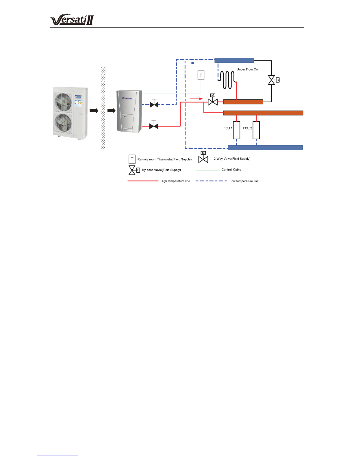
4. Installation Example
CASE 1: Connecting Under oor Coil and Fan Coil Unit
Outdoor Indoor
Notes
(a) The two-way valve is very important to prevent dew condensation on the oor and FCU while cooling mode;
(b) Type of thermostat and specication should be complied with installation of this manual;
(c) The bypass valve must be installed to secure enough water flow rate, and should be installed at the
collector.
(d) When the FCU and the underoor coil are used at the same time, performance of the underoor coil is
satised rstly. When performance of the FCU is required, then “Floor cong” should be set to “Without”.

Air-to-water Heat Pump Split Versati
12
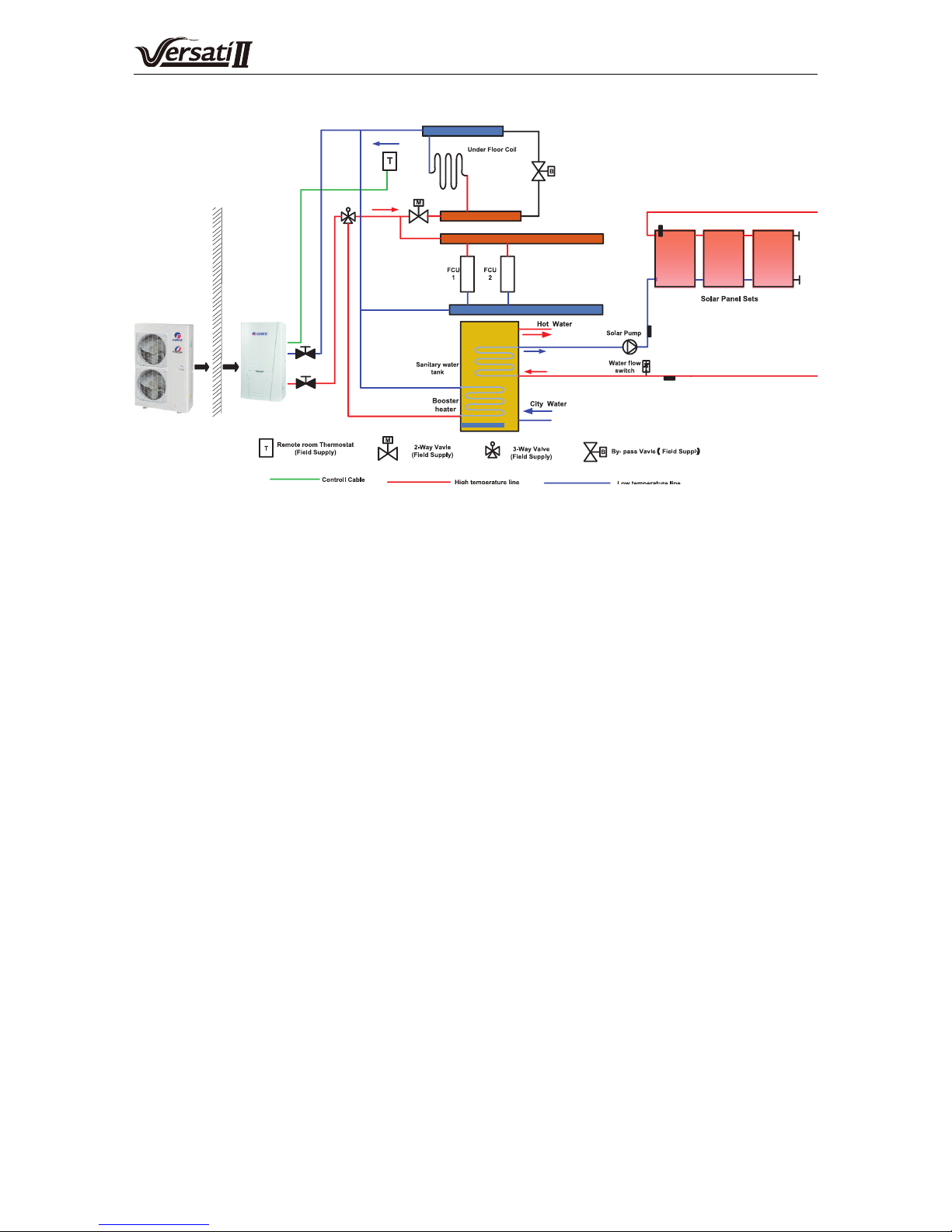
CASE 2: Connecting Under oor Coil, Fan Coil Unit and Water Tank
Outdoor Indoor
Notes
(a) The two-way valve is very important to prevent dew condensation on the oor and FCU while cooling mode
(b) In this case, three-way valve should be installed and should be complied with installation of this manual;
(c) When the FCU and the underoor coil are used at the same time, performance of the underoor coil is
satised rstly. When performance of the FCU is required, then “Floor cong” should be set to “Without”.
(d) Anitary water tank should be equipped with internal electric heater to secure enough heat energy in the
very cold days.
Air-to-water Heat Pump Split Versati
13
CASE 3 : Connecting Under oor Coil, Fan Coil Unit , Water Tank and Solar System
Outdoor
Indoor
Notes
(a) The two-way valve is very important to prevent dew condensation on the oor and FCU while cooling mode
(b) In this case, three-way valve should be installed and should be complied with installation of this manual;
(c) Anitary water tank should be equipped with internal electric heater to secure enough heat energy in the
very cold days.
(d) When the FCU and the underoor coil are used at the same time, performance of the underoor coil is
satised rstly. When performance of the FCU is required, then “Floor cong” should be set to “Without”.
(e) For the solar heating system, only the control port is available and relative accessories are absent.
Air-to-water Heat Pump Split Versati
14
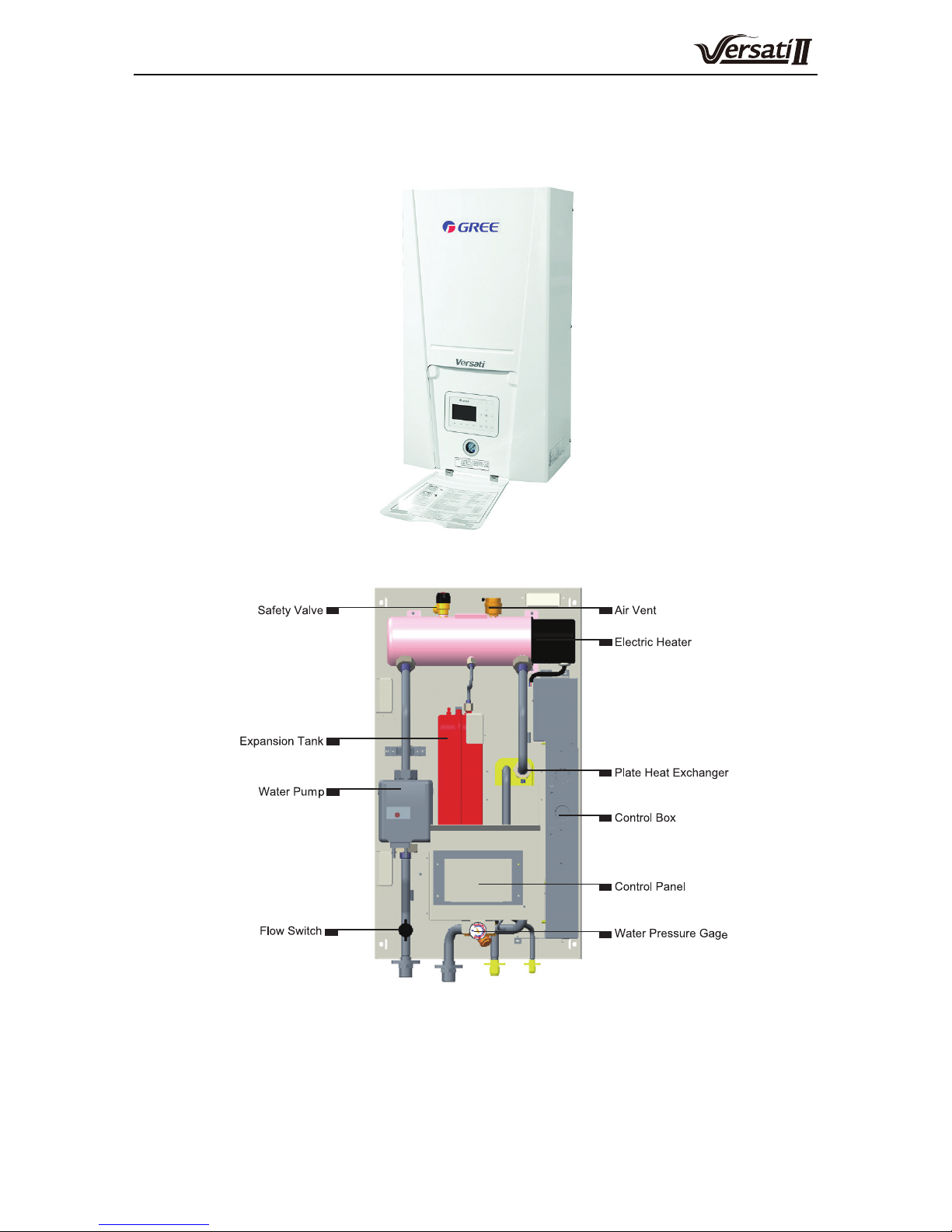
5. Main Components
5.1 Indoor unit
(1) GRS-CQ8.0Pd/NaE-K(I),GRS-CQ10Pd/NaE-K(I)
External
Internal
Air-to-water Heat Pump Split Versati
15
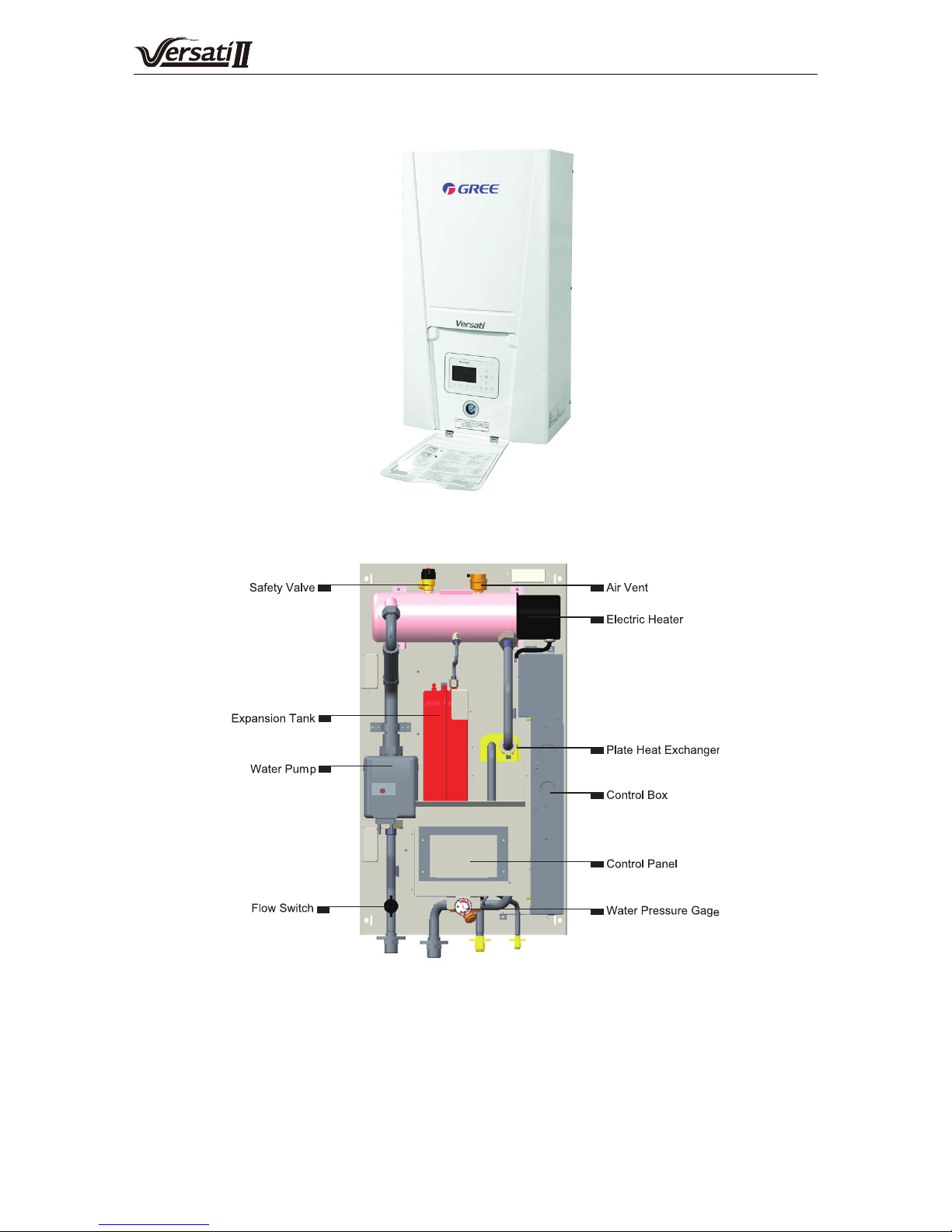
(2) GRS-CQ12Pd/NaE-K(I), GRS-CQ14Pd/NaE-K(I), GRS-CQ16Pd/NaE-K(I), GRS-CQ12Pd/NaE-M(I)GRS-
CQ14Pd/NaE-M(I), GRS-CQ16Pd/NaE-M(I)
External
Internal
 Loading...