

Gree GRS-2.4/D270ANbA-K, GRS-1.5/D150ANbA-K, GRS-1.5/TD150ANbA-K, GRS-1.5/TD200ANbA-K, GRS-1.5/D200ANbA-K Service Manual

AIR SOURCE HEAT PUMP WATER HEATER
Capacity: 1.5~2.4kW
Rated Frequency: 50Hz
Operation Range : -7℃~45℃

Contents
PRODUCT ............................................................................................................................................................. 2
1 MODELS LIST .......................................................................................................................................................... 2
2 NOMENCLATURE ................................................................................................................................................... 3
3 FUNCTION ................................................................................................................................................................ 3
4 PRODUCT PARAMETERS ..................................................................................................................................... 4
5 WORKING PRINCIPLE .................................................................................................................................................. 7
6 OPTIONAL ACCESSORIES ........................................................................................................................................... 8
CONTROL ........................................................................................................................................................... 10
1 UNIT CONTROL .......................................................................................................................................................... 10
2 WIRED CONTROLLER ................................................................................................................................................ 11
3 QUERY PARAMETERS ................................................................................................................................................ 13
4 OPERATION INSTRUCTIONS ....................................................................................................................................... 14
INSTALLATION ................................................................................................................................................... 24
1 ENGINEERING INSTALLATION FLOWCHART .............................................................................................................. 24
2 PREPARATIONS ......................................................................................................................................................... 25
3 INSTALLATION OF THE UNIT OF WATER HEATER ...................................................................................................... 28
4 PIPE INSULATION ....................................................................................................................................................... 40
5 ELECTRIC INSTALLATION .......................................................................................................................................... 40
6 CHECK FOR ACCEPTANCE AFTER INSTALLATION .................................................................................................... 44
COMMISSIONING AND TRIAL RUN ................................................................................................................. 46
1 COMMISSIONING FLOWCHART .................................................................................................................................. 46
2 PRECAUTIONS ON SAFETY ........................................................................................................................................ 46
3 PREPARATIONS ......................................................................................................................................................... 46
4 COMMISSIONING AND TRIAL RUN ............................................................................................................................. 49
5 CHECK BEFORE ACCEPTANCE ................................................................................................................................. 51
6 UNIT FUNCTION SETTING .......................................................................................................................................... 52
MAINTENANCE .................................................................................................................................................. 54
1 FAULT CODE .............................................................................................................................................................. 54
2 TROUBLESHOOTING .................................................................................................................................................. 55
3 REPAIR OF KEY COMPONENTS ................................................................................................................................. 58
4 EXPLODED VIEW AND PARTS LIST ........................................................................................................................... 62
UNIT MAINTENANCE ........................................................................................................................................ 69
1 WATER REPLENISHMENT FOR THE WATER TANK ..................................................................................................... 69
2 REGULAR CLEANING FOR THE WATER TANK ........................................................................................................... 69
3 SAFETY VALVE MAINTENANCE ................................................................................................................................. 69
4 MAINTENANCE OF THE UNIT ..................................................................................................................................... 70
ATTACHMENT: MAPPING TABLE OF THE TEMPERATURE SENSOR RESISTANCE AND
TEMPERATURE .................................................................................................................................................. 71

GREE AIR SOURCE HEAT PUMP WATER HEATER SERVICE MANUAL
PRODUCT
1
GREE AIR SOURCE HEAT PUMP WATER HEATER SERVICE MANUAL
Product type
Model
Product
Code
Heating capacity
(W)
Outline diagram
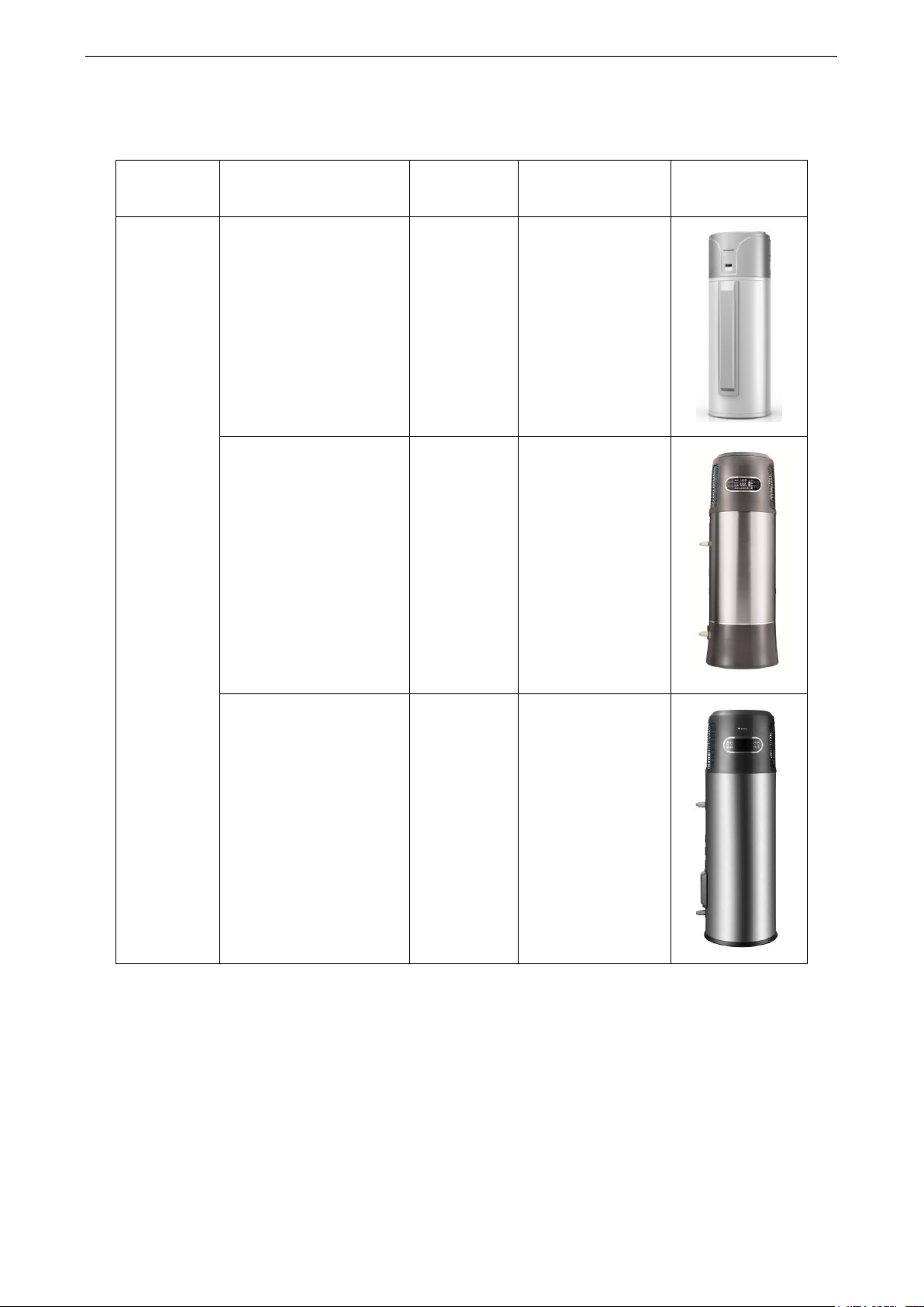
Integral type
GRS-2.4/D270ANbA-K
ER02100050
2400+1500
(electric heating)
GRS-1.5/D150ANbA-K
GRS-1.5/D200ANbA-K
ER02100070
ER02100080
1500+1500
(electric heating)
GRS-1.5/TD150ANbA-K
GRS-1.5/TD200ANbA-K
ER02100100
ER02100090
1500+1500
(electric heating)
PRODUCT
1 MODELS LIST
Notes:
① The above table lists specifications of the air source water heater series product for static heat up. The
product standard is EN16147-2011, (EU) No 814/2013, EN 12102-2008.
② Conditions for testing heating capacity of the unit: outdoor ambient temperature: 20°C DB/15°C WB;
Initial/ending water temperature in the water tank: 15°C /55°C .
③ For units with a water tank equipped with an electrical heater, that is, the model of which includes ― D ‖,
both the heat pump and electrical heater are started for heat up under low ambient temperature or rapid
mode.
④ If the product specification changes with product improvement, refer to the parameter specified on the
nameplate.
2

GREE AIR SOURCE HEAT PUMP WATER HEATER SERVICE MANUAL
GRS
-
1.5 / T D 200 A Nb A - K 1 2 3 4 5 6 7 8 9 10
11
12
13
14 15 No.
Description
Options
1
Product code
GRS—heat pump water heater
2
Heating capacity code
Nominal heating capacity (Unit: kW)
3
Compressor system
Null for single compressor; S—two compressors
4
Functions 1
P— inverter; Pd—DC inverter; M—modular for fixed speed; PM—AC
inverter modular; PdM—DC inverter modular; Null for fixed speed
5
Functions 2
Null for general; Re—Low temp heat pump
6
Material of water tank
Null for stainless steel; T—Porcelain enamel
7
Function code
Null for no electric heating function; D—with electric heating function
8
Water tank capacity
Capacity of water tank; Unit:(L)
9
Design code
A—LCJW: floor standing type; outer coil pipe static heating type;
B—BCJW: wall-mounted type; outer coil pipe static heating type;
C—LCJ: floor standing type; built-in coil pipe static heating type;
D—BCJ: wall-mounted type; built-in coil pipe static heating type;
10
Water tank shape
Null for rotundity; F—squareness
11
Inner tank number
Null for one inner tank; 2—two inner tank
12
Refrigerant
Null for R22; R407c—N; R410A—Na; R134a—Nb; R417A—Ne
13
Design Serial number
A, B, C…or A1, A2…, B1, B2…
14
Cycle function
H—cycle function; Null for
no
cycle function
15
Power supply code
M—380-415V 3PH~50Hz; K—220V-240V 1PH~50Hz;
D—220V-240V 1PH~60Hz; …
No.
Name
Function
1
Compressor
Increases pressure for the refrigerant and provides driving force for
circular flow of the refrigerant as a main driving component.
2
Four-way valve
Reverses flow direction of the refrigerant when the system
switches between the normal heat up mode and defrosting mode.
3
Water tank
Provides heat exchange channel for refrigerant and water and
stores hot water for daily use.
4
Electronic expansion
valve
Speeds up high-pressure and high-temperature refrigerant and
reduces pressure and adjusts the circulation amount of coolant.
5
Finned tube
exchanger
Provides heat exchange channel for refrigerant and air.
6
Fan motor
Enhances heat exchange on the air side of the finned tube
exchange and provides a low-temperature heat source
continuously.
7
Filter
Filters impurities in refrigerant to protect components with small
diameter.
2 NOMENCLATURE
3 FUNCTION
3

GREE AIR SOURCE HEAT PUMP WATER HEATER SERVICE MANUAL
Model
GRS-2.4/D270ANbA-K
Rated Heating Capacity(*)
W
2400
Rated Input Power(*)
W
685
COP(*)
W/W
3.50
Capacity
L
270
Load Profile
-
XL
COP
DHW
(**)
W/W
2.61
Energy Efficiency Class(**)
- A Water Heating Energy Efficiency(**)
-
105%
Annual electricity consumption
(average climate conditions)
kWh
1594
Maximum Input Power
W
1300+1500W (Electric Heater)
Outlet Water Temperature
°C
Default: 55°C , 35°C ~70°C
Power Supply
-
220V-240V ~50Hz
Insulation Level
-
Ⅰ
Protection of Ingression
-
ⅠPX4
Refrigerant
Name
R134a
Charge
kg
1.10
Outline Dimensions
W x D x H
mm
660×667×1958
Package Dimensions
W x D x H
mm
813×813×2100
Net Weight
kg
114
Sound Power Level(***)
dB(A)
60
Operating Range
°C
-7~45
4 PRODUCT PARAMETERS
4.1 Product Parameters
Notes:
① (*) Value obtained with the following conditions: Outdoor temperature: 20°C DB /15°C WB; Water
tank temperature (start/end): 15°C /55°C.
② (**)Value obtained with an air temperature of 7°C and a water inlet at 10℃, as per EN16147-2011,
(EU) No 814-2013.
③ (***) Value obtained indoor placement, with 2m long inlet and outlet wind duct, as per EN
12102-2008, (EU) No 814-2013.
④ The installation of suction and backflow conduits on the heat pump lessens its performance.
⑤ Under RAPID function, electric heater helps to heating water.
⑥ Please always see the nameplate for the exact data as this table is subject to change.
4

GREE AIR SOURCE HEAT PUMP WATER HEATER SERVICE MANUAL
Model
GRS-1.5/D150ANbA-K
GRS-1.5/D200ANbA-K
Rated Heating Capacity
(*)
W
1500
1500
Rated Input Power
(*)
W
429
429
COP
(*)
W/W
3.50
3.50
Capacity
L
150
190
Load Profile
-
L L COP
DHW
(**)
W/W
2.47
2.47
Energy Efficiency Class
(**)
-
A
A
Water Heating Energy Efficiency
(**)
-
103.9%
103.9%
Annual electricity consumption
(average climate conditions)
kWh
985
985
Maximum Input Power
W
650+1500W (Electric Heater)
Outlet Water Temperature
°C
Default: 55°C , 35°C ~70°C
Power Supply
-
220V-240V ~50Hz
Insulation Level
-
Ⅰ
Ⅰ
Protection of Ingression
-
ⅠPX4
ⅠPX4
Refrigerant
Name
R134a
R134a
Charge
kg
0.8
0.8
Outline Dimensions
W×D×H
mm
591×591×1685
591×591×1935
Package Dimensions
W×D×H
mm
703×703×1765
703×703×2015
Gross/Net Weight
kg
88.0/73.5
95.5/79.0
Sound Power Level
(***)
dB(A)
61
61
Operating Range
°C
0~45
0~45
Notes:
① (*) Value obtained with the following conditions: Outdoor temperature: 20°C DB /15°C WB; Water
tank temperature (start/end): 15°C /55°C.
② (**) Value obtained with an air temperature of 7°C and a water inlet at 10℃, as per EN16147-2011,
(EU) No 814-2013.
③ (***) Value obtained indoor placement, as per EN 12102-2008, (EU) No 814-2013.
④ Under Rapid function, electric heater helps to heating water.
⑤ Please always see the nameplate for the exact data as this table is subject to change.
5
GREE AIR SOURCE HEAT PUMP WATER HEATER SERVICE MANUAL
Model
GRS-1.5/TD150ANbA-K
GRS-1.5/TD200ANbA-K
Rated Heating Capacity
(*)
W
1500
1500
Rated Input Power
(*)
W
429
429
COP
(*)
W/W
3.50
3.50
Capacity
L
150
190
Load Profile
-
L L COP
DHW
(**)
W/W
2.47
2.24
Energy Efficiency Class
(**)
-
A
A
Water Heating Energy Efficiency
(**)
-
104%
95%
Annual electricity consumption
(average climate conditions)
kWh
985
1075
Maximum Input Power
W
650+1500W (Electric Heater)
Outlet Water Temperature
°C
Default: 55°C , 35°C ~70°C
Power Supply
-
220V-240V ~ 50Hz
Insulation Level
-
Ⅰ
Ⅰ
Protection of Ingression
-
ⅠPX4
ⅠPX4
Refrigerant
Name
R134a
R134a
Charge
kg
0.8
0.8
Outline Dimensions
W×D×H
mm
621×561×1760
621×561×2030
Package Dimensions
W×D×H
mm
731×717×1845
731×717×2110
Gross/Net Weight
kg
112.0/92.0
122.5/102.5
Sound Power Level
(***)
dB(A)
62
62
Operating Range
°C
0~45
0~45
Models
GRS-2.4/D270ANbA-K
GRS-1.5/D150ANbA-K
GRS-1.5/D200ANbA-K
GRS-1.5/TD150ANbA-K
GRS-1.5/TD200ANbA-K
Heating
-7~45°C
0~45°C
0~45°C
Note: The above value range indicates the outdoor ambient temperate range for normal operation of the
unit. For details on the configurable range of water temperature, see the nameplate of the water tank.
Notes:
① (*) Value obtained with the following conditions: Outdoor temperature: 20°C DB/15°C WB; Water
tank temperature (start/end): 15°C /55°C.
② (**) Value obtained with an air temperature of 7°C and a water inlet at 10℃, as per EN16147-2011,
(EU) No 814-2013.
③ (***) Value obtained indoor placement, as per EN 12102-2008, (EU) No 814-2013.
④ Under Rapid function, electric heater helps to heating water.
⑤ Please always see the nameplate for the exact data as this table is subject to change.
4.2 Work Temperature Range
6
GREE AIR SOURCE HEAT PUMP WATER HEATER SERVICE MANUAL
5 Working Principle
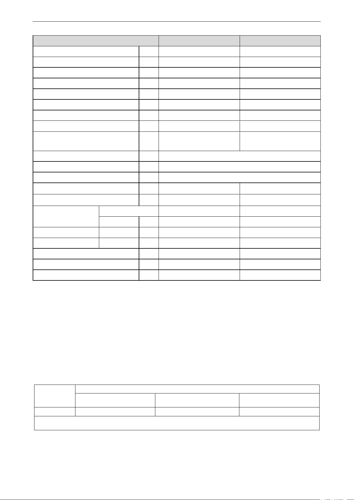
5.1 Brief Introduction to Working Principle
As the refrigerant has different phase-transition temperature under varied pressure, it enables the
heat pump to transfer heat of low-temperature heat source to the high-temperature heat source. The air
source water heater unit utilizes the heat pump to obtain heat from the ambient low-grade energy (air
source) via thermodynamic cycle by consuming partial electrical energy, and then delivers heat to the
water tank for heating up water.
5.2 Working Diagram
The compressor consumes partial electrical energy to compress the refrigerant into
high-temperature and high-pressure gas. After entering the condenser (the water tank coil of a water
heater in static heat up mode), the gaseous refrigerant transfers its heat to water as its saturation
temperature is higher than the water temperature and leaves the condenser after condensing into liquid.
The liquid refrigerant enters the throttling device (generally the electronic expansion valve) for speedup
and pressure reduction. As partial liquid vaporizes, the liquid refrigerant has two states (gas and liquid)
when leaving the throttling device. The low-pressure refrigerant enters the vaporizer (the finned tube
exchanger of a water heater in static heat up mode) and is vaporized into liquid after absorbing heat from
air as its saturation temperature is lower than the air temperature. The low-pressure gas is inhaled by the
compressor for the next cycle.
7

GREE AIR SOURCE HEAT PUMP WATER HEATER SERVICE MANUAL
Item
Model/Coding
Remark
Intelligent preheat water return device
(transient heat up module)
HS-01
Self-regulation heating belt
76612816
Pressure stabilizing valve
07382812
6 Optional Accessories
The Gree air source water heater unit supports the following accessories:
Note:
If any of the preceding accessories is required, contact with the local sales company.
8

GREE AIR SOURCE HEAT PUMP WATER HEATER SERVICE MANUAL
CONTROL
9
GREE AIR SOURCE HEAT PUMP WATER HEATER SERVICE MANUAL
CONTROL
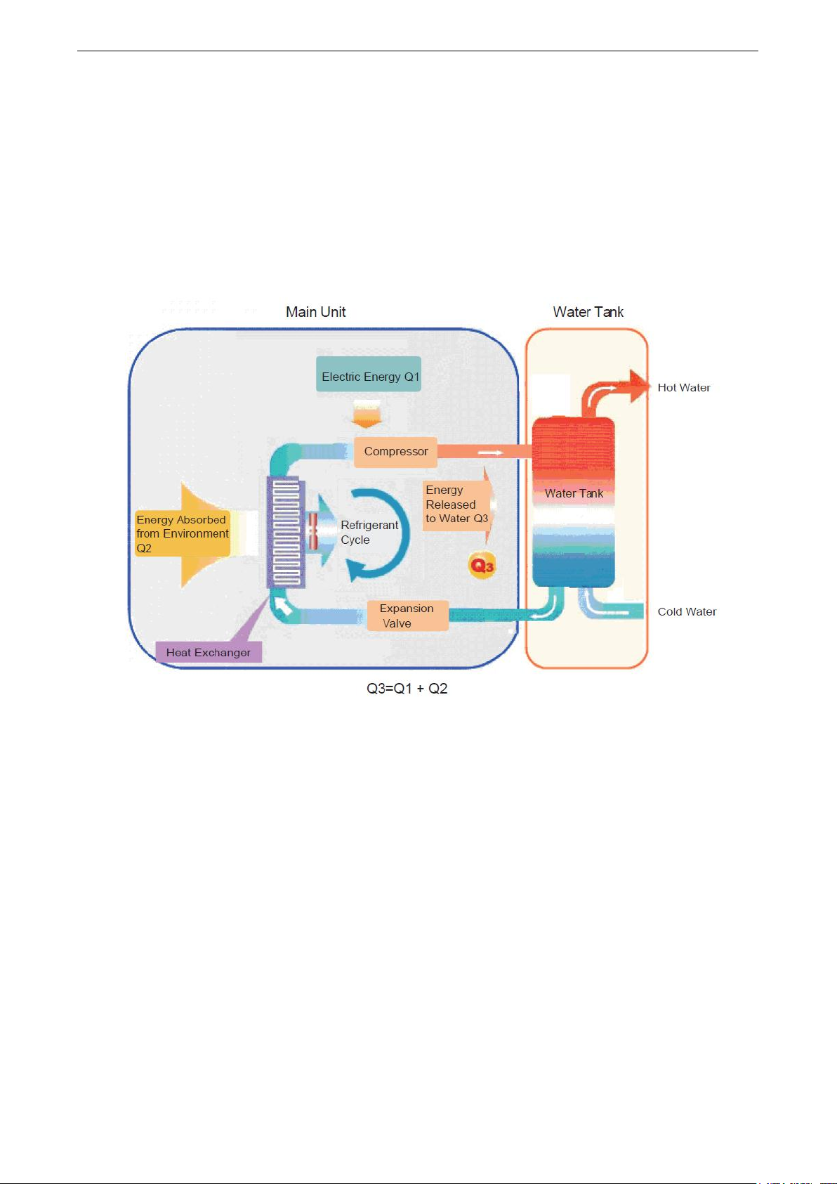
1 Unit Control
1.1 Overall Control Logic
(1) High pressure switch
When the detected voltage exceeds the preset value, a fault will be displayed and the unit will stop or
not start.
(2) Temperature sensor fault detection and handling
Once the temperature sensor for the ambient temperature, air discharge, air inhaling, pipe
temperature, or water tank is open-circuited or short-circuited, the corresponding fault code will be
displayed and all loads will be cut off. After the fault is rectified, the unit automatically runs again.
1.2 Key Control Logics
(1) Control on compressor
After power is connected, start the system by the manual operator and detect the outdoor ambient
10
GREE AIR SOURCE HEAT PUMP WATER HEATER SERVICE MANUAL
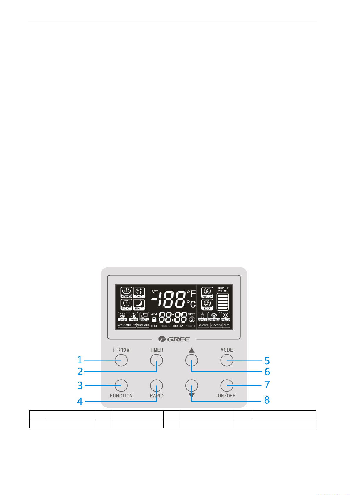
1
i-know button
2
Timer button
3
Function button
4
Rapid button
5
Mode button
6
Increase button
7
On/Off button
8
Decrease button
temperature sensor. If the outdoor ambient temperature is not lower than -7°C (0°C of
GRS-1.5/D150ANbA-K、GRS-1.5/D200ANbA-K、GRS-1.5/TD150ANbA-K、GRS-1.5/TD200ANbA-K) and
when no fault is detected and start up conditions of the compressor are met, the system starts by following
the hot water sequence.
(2) Control on fan motor
When start up conditions of the compressor are met, the system starts by following the hot water
sequence. The electronic expansion valve resets and is initialized, and the external fan motor starts. After
10s, the compressor starts. The fan motor will determine whether to still run at high level or to run at low
level based on the ambient temperature after it runs at high level. If the system enters overload control,
the fan motor will switch to discontinuous start up and shutdown status at low level.
(3) Control on defrosting
When the compressor is initially powered on and started, it determines the defrosting condition after
running for the preset duration. If the defrosting condition is met, the system defrosts before running in hot
water mode (including freeze-proofing operation of compressor). After defrosting is over, the compressor
starts for heat up. When the cumulative operation time exceeds or equals to the preset time for defrosting,
defrosting will be performed if the relation between the outdoor exchanger pipe temperature sensor Th
and the outdoor ambient temperature sensor Te meets the defrosting condition.
(4) Control on freeze-proofing function
In the Off state, if water temperature in the water tank detected by the system based on the ambient
temperature is too low, the unit starts the freeze-proofing function immediately.
2 Wired Controller
(1) Controller for GRS-2.4/D270ANbA-K:
11
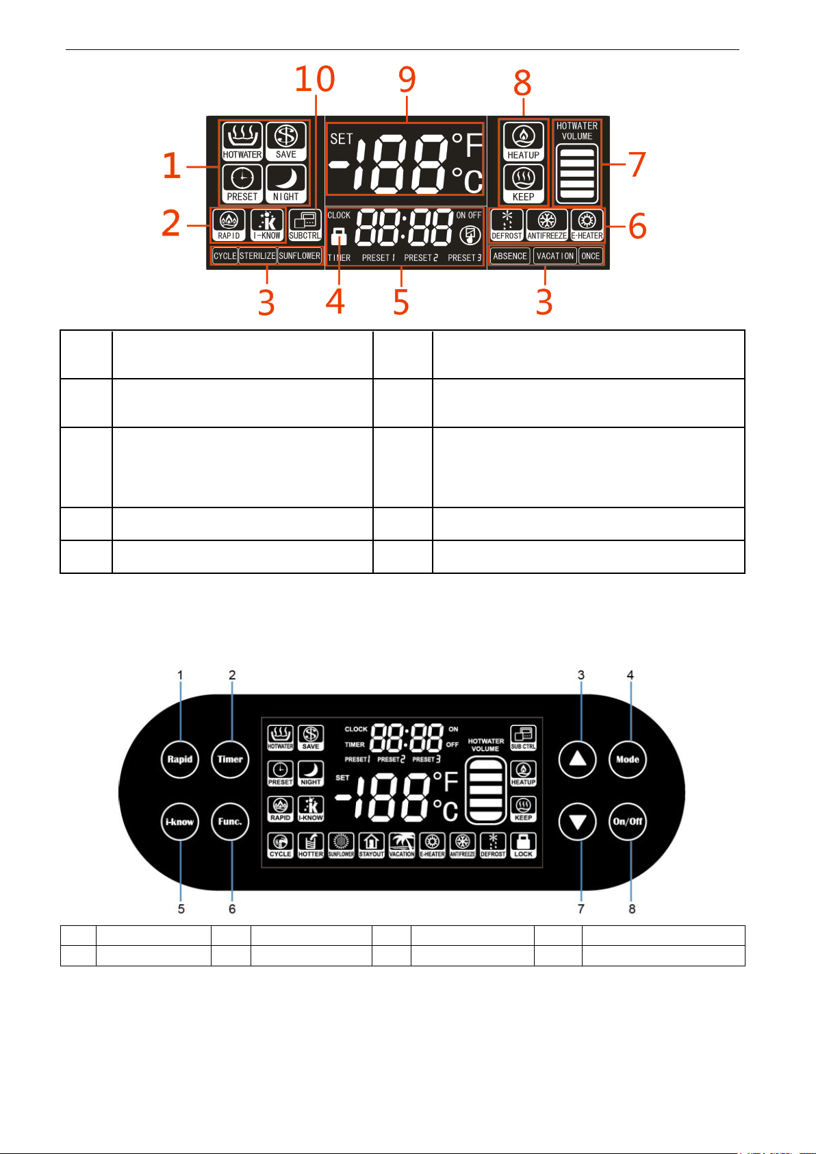
GREE AIR SOURCE HEAT PUMP WATER HEATER SERVICE MANUAL
1
Display of Common Operation Modes:
HOTWATER, SAVE, PRESET and
NIGHT mode.
6
Display of defrost, antifreeze running, and
e-heater running (or display of the Special
E-HEATER Mode).
2
Display of RAPID and i-know function.
7
Display of hot water volume (this function is
unavailable to models with single temperature
sensor).
3
Display of CYCLE, STERILIZE,
SUNFLOWER, ABSENCE, VACATION,
and ONCE function (the STERILIZE
function may not work for models without
an electrical heater).
8
Display of operating/standby.
4
Display of Keypad Lock function.
9
Display of actual water temperature, temperature
setpoint, error codes, and running parameters.
5
Display of system time, preset time,
timer setting and running parameters.
10
Display of the sub-controller. (This function is
reserved.)
1
Rapid button
2
Timer button
3
Increase button
4
Mode button
5
i-know button
6
Function button
7
Decrease button
8
On/Off button
(2) Controller for GRS-1.5/D150ANbA-K, GRS-1.5/D200ANbA-K, GRS-1.5/TD150ANbA-K,
GRS-1.5/TD200ANbA-K:
12
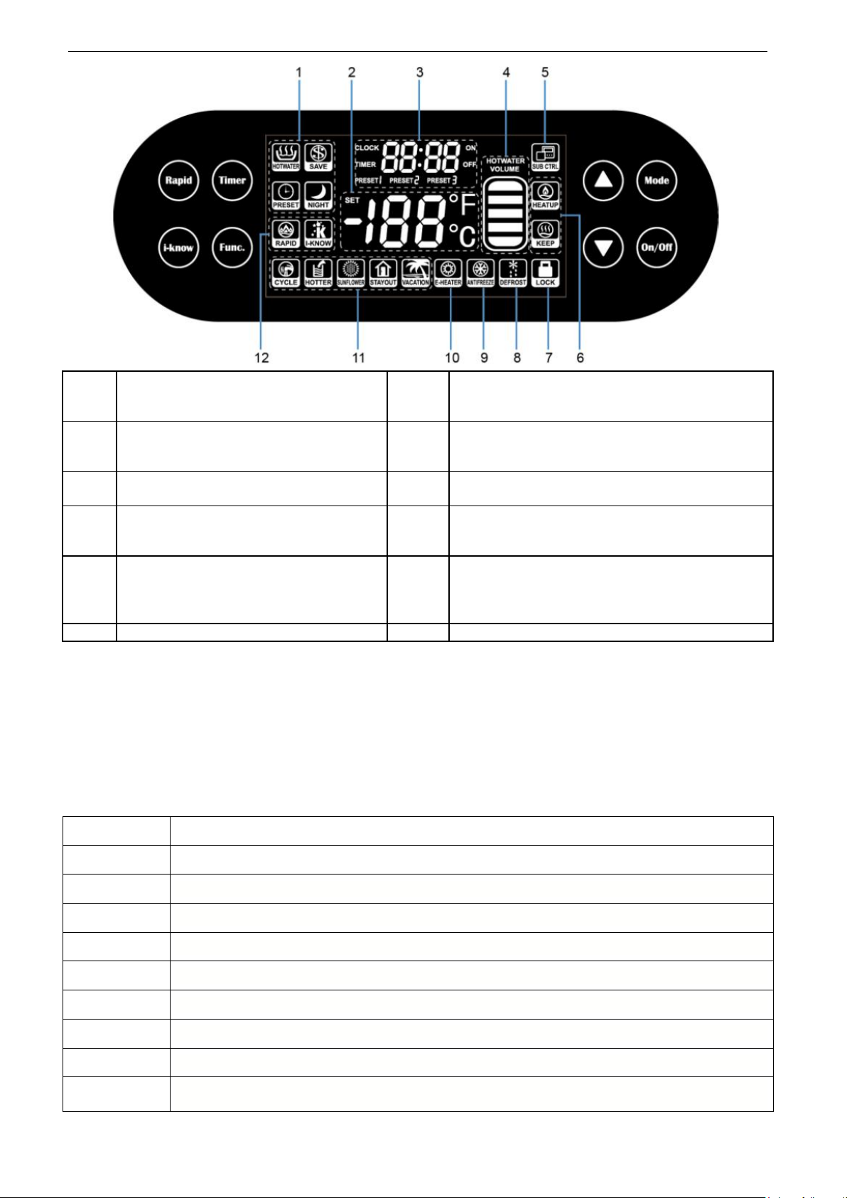
GREE AIR SOURCE HEAT PUMP WATER HEATER SERVICE MANUAL
1
Display of Common Operation Modes:
HOTWATER, SAVE, PRESET and
NIGHT mode.
7
Display of Keypad Lock function.
2
Display of actual water temperature,
temperature setpoint, error codes, and
running parameters.
8
Display of defrost running
3
Display of system time, preset time,
timer setting and running parameters.
9
Display of antifreeze running
4
Display of hot water volume (this
function is unavailable to models with
single temperature sensor).
10
Display of e-heater running
5
Display of the sub-controller. (This
function is reserved.)
11
Display of CYCLE, HOTTER,
SUNFLOWER, STAYOUT and VACATION
function (the HOTTER function may not work for
models without an electrical heater).
6
Display of operating/standby.
12
Display of RAPID and i-know function.
Query Code
Query Parameter
00
00 by default
01
Communication protocol version
03
Temperature of the upper temperature sensor of the water tank (detected by the mainboard)
04
Temperature of the outdoor ambient temperature sensor
06
Temperature of the air intake temperature sensor
08
Temperature of the air exhaust temperature sensor
13
Temperature of the temperature sensor for outdoor pipe
16
Temperature of the lower temperature sensor of the water tank (detected by the mainboard)
17
Display of single or dual temperature sensor (01 indicates single temperature sensor and 02
indicates dual temperature sensor)
3 Query Parameters
This function is provided for the debugging personnel to query running status of the unit. After
pressing and holding MODE+▲ button for 5s, the parameter display area blinks. 00 is displayed by default.
The ▲ and ▼ buttons can be pressed to switch the query item.
Query codes are described in the following table.
13
GREE AIR SOURCE HEAT PUMP WATER HEATER SERVICE MANUAL
HOTWATER SAVE
PRESET
NIGHT
4 Operation Instructions
4.1 On/Off Setting
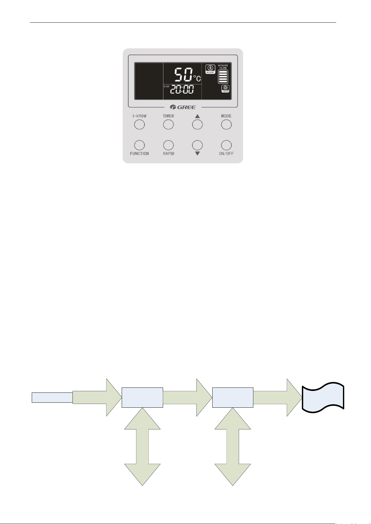
The unit will be started or stopped by pressing the ―On/Off ‖ button.
Note: After energization and under normal communication, the LCD will display the water temperature,
time, and hot water volume (for models with dual temperature sensor) under both On and Off states of the
unit. It means the Off state if the LCD does not display the running mode, as shown in the following figure.
4.2 Common Modes Setting
In the On state of the unit, press the MODE button to switch the operation modes in the following
sequence:
The HOTWATER mode is shown in the following figure.
4.3 Special Modes Setting
If the heat pump of a water heater equipped with an electrical heater is faulty, users can press and
hold MODE+RAPID for 5s in any mode under the state to enter the E-HEATER mode.
Note: The E-HEATER mode can be used only when the heat pump is faulty. In this case, contact the
14
GREE AIR SOURCE HEAT PUMP WATER HEATER SERVICE MANUAL
Main interface
Hour value of the
system time
blinks.
Minute value of
the system time
blinks.
Press and hold the
TIMER button.
Press the TIMER
button.
Press ▲ or ▼ to
adjust the value.
Press ▲ or ▼ to
adjust the value.
Press the TIMER
button.
Setting is
complete.
aftersales service immediately.
The E-HEATER mode is shown in the following figure.
In the E-HEATER mode, users can press the MODE button to switch to the HOTWATER mode. Note
that the E-HEATER mode will be cancelled automatically and the HOTWATER mode will be started upon
restart of the water heater in the case of blackout.
4.4 Water Temperature Setting
In the On state, press ▲ to increase or press ▼ to decrease the temperature setpoint. The water
temperature will increase or decrease continuously by 1°C when the button is pressed and held.
The minimum temperature setpoint for all models is 35°C. The maximum temperature setpoint can be
set to 70°C.
4.5 Time Setting
4.5.1 System Time Setting
In the main interface, press and hold the TIMER button for 5s. The system time setting interface is
displayed. The clock icon is on and the hour value blinks. Press ▲ or ▼ to adjust the hour value and
press the TIMER button to confirm setting. Then the minute value flickers. Press ▲ or ▼ to adjust the
minute value and press the TIMER button to confirm setting. After system time setting is saved, the main
interface is displayed. In the setting process, if no button is pressed within 15s, the main interface will be
displayed and setting will not be saved.
The system time ranges from 00:00 to 23:59. Each time you press ▲ or ▼, the time increases or
decreases by 1 hour or 1 minute. When the button is pressed and held, the time increases or decreases
continuously by 1 hour or 1 minute.
The setting process is shown in the following figure.
15
GREE AIR SOURCE HEAT PUMP WATER HEATER SERVICE MANUAL
4.5.2 Timer Setting
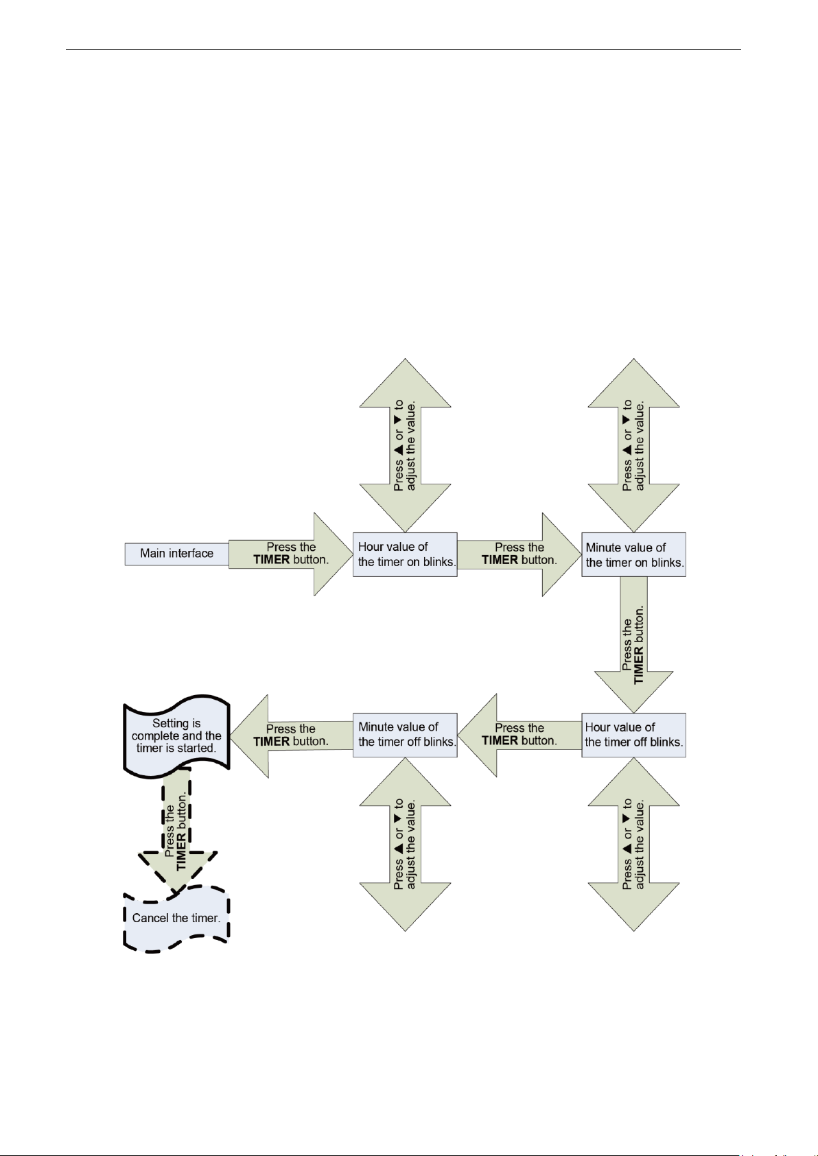
Timer setting: Under the HOTWATER or SAVE mode or under the Off state, press the TIMER
button to enter the timer setting interface. The TIMER and ON icons are on and the hour value blinks.
Press ▲ or ▼ to adjust the hour value and press the TIMER button to confirm setting. Then the minute
value flickers. Press ▲ or ▼ to adjust the minute value and press the TIMER button to confirm setting.
Then the OFF icon is on and ON icon is off. The hour value blinks. Press ▲ or ▼ to adjust the hour value
and press the TIMER button to confirm setting. Then the minute value flickers. Press ▲ or ▼ to adjust the
minute value and press the TIMER button to confirm setting. After the scheduled on/off time setting is
saved, the main interface is displayed. In the setting process, if no button is pressed within 15s, the main
interface will be displayed and setting will not be saved.
Timer cancelling: After the scheduled on/off time is set, press the TIMER button to cancel it.
Note: The scheduled on time and off time cannot be the same; otherwise, the LCD switches to the
interface for resetting the timer.
4.5.3 Preset Time Setting
In the PRESET mode, hot water is prepared in advance by the preset time.
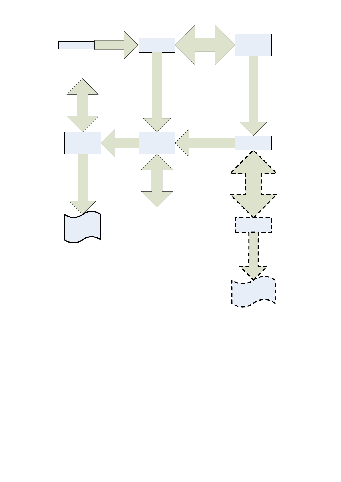
In the main interface of the PRESET mode, press the TIMER button to enter the selection interface.
PRESET 1 blinks while PRESET 2 and PRESET 3 are not displayed. Press ▲ or ▼ and the LCD blinks
16

GREE AIR SOURCE HEAT PUMP WATER HEATER SERVICE MANUAL
circularly in the flowing sequence: PRESET 1 – PRESET 2 – PRESET 3 – PRESET 1.
Preset time setting: Press the TIMER button to select PRESET 1. Then the PRESET 1 icon is on
and the hour value blinks. Press ▲ or ▼ to adjust the hour value and press the TIMER button to confirm
setting. Then the minute value flickers. Press ▲ or ▼ to adjust the minute value and press the TIMER
button to confirm setting. After time setting for PRESET 1 is saved, the main interface is displayed.
PRESET 2 or PRESET 3 setting: Press the TIMER button to select PRESET 2 and then the ON icon
blinks. Press ▲ or ▼ to switch the ON and OFF icons. When the ON icon blinks, press the TIMER button.
Then the PRESET 2 icon is on and the ON icon is off. The hour value blinks. Press ▲ or ▼ to adjust the
hour value and press the TIMER button to confirm setting. Then the minute value flickers. Press ▲ or ▼
to adjust the minute value and press the TIMER button to confirm setting. After time setting for PRESET 2
is saved, the main interface is displayed. The method for setting PRESET 3 is the same as that for
PRESET 2. (After setting is saved, the ON and OFF icons are not displayed in the main interface as these
icons are available in the setting process.)
In the time presetting process, if no button is pressed within 15s, the preset interface will switch to the
main interface automatically and setting will not be saved.
If the time preset for PRESET 1, PRESET 2, and PRESET 3 is the same, it is regarded as one timer.
The preset time can be memorized. If the preset time does not need to be reset, users only need to
select on or off.
Preset time cancelling: After time is preset for PRESET 2 or PRESET 3, users can press the TIMER
button to display the selection interface. The icon of PRESET 2 blinks. Press ▲ or ▼ and the LCD blinks
circularly in the flowing sequence: PRESET 2 – PRESET 3 – PRESET 1 – PRESET 2. Select PRESET 2
and press the TIMER button. Select to cancel PRESET 2. Then the PRESET 2 icon is on and the ON icon
blinks. Press ▲ or ▼ to select OFF. Press the TIMER button to confirm cancelling and return to the main
interface. The method for cancelling preset time for PRESET 3 is the same as that for PRESET 2. Preset
time for PRESET 1 cannot be cancelled. If users select PRESET 1, the time setting interface will be
displayed.
17
GREE AIR SOURCE HEAT PUMP WATER HEATER SERVICE MANUAL
Main interface
PRESET 1
blinks.
The ON icon
blinks.
Press the
TIMER button.
Press ▲ or ▼ to select
PRESET X
The hour value
of PRESET X
blinks.
Press ▲ or ▼ to
adjust the value.
Press the
TIMER button.
The minute
value of
PRESET X
blinks.
Press the TIMER button.
Press the TIMER button.
The OFF icon
blinks.
PRESET 1 or
PRESET 3
blinks.
Press the TIMER button.
Press the TIMER button.
Press ▲ or ▼ to adjust
the value.
Press the
TIMER
button
.
Press
▲
or
▼
to
select on or off
.
Setting is complete
and PRESET X is
canceled.
Setting is
complete and
PRESET X is
started.
and ambient temperature and stops one hour after the preset time.
4.6 Function Setting
4.6.1 i-know
the i-know button again.
4.6.2 RAPID
for heat up. To cancel this function, press the RAPID button again. Then electrical heater is stopped.
To return to the E-HEATER mode, press the RAPID button again.
The PRESET mode runs circularly. The water heater starts to heat up water based on the preset time
In the on state, press the i-know button to select the i-know function. To cancel this function, press
In the on state, press the RAPID button to select the RAPID function. The electrical heater is started
Under the E-HEATER mode, users can press the RAPID button to switch to the HOTWATER mode.
4.6.3 SUNFLOWER, ABSENCE, and ONCE
In the on state, press the FUNCTION button to enter the interface for selecting among the
SUNFLOWER, ABSENCE, and ONCE functions. When a function is selected, the corresponding icon
18
GREE AIR SOURCE HEAT PUMP WATER HEATER SERVICE MANUAL
Sterilization Parameter
Meaning
Range
d value
Day interval for circular
sterilization
0-10 days; 0 indicates sterilization for once only and
the sterilization function will be canceled after being
performed.
h value
Time point for circular
sterilization
00:00-23:00
blinks. Then users can press ▲ or ▼ to start or cancel this function. If no operation is performed within 5s,
it will be regarded that this function is not required. If this function is started, the function icon is displayed
without blinking. If this function is cancelled, the function icon will not be displayed. If no function is
selected in setting interface for 5s, the interface switches back to the original status.
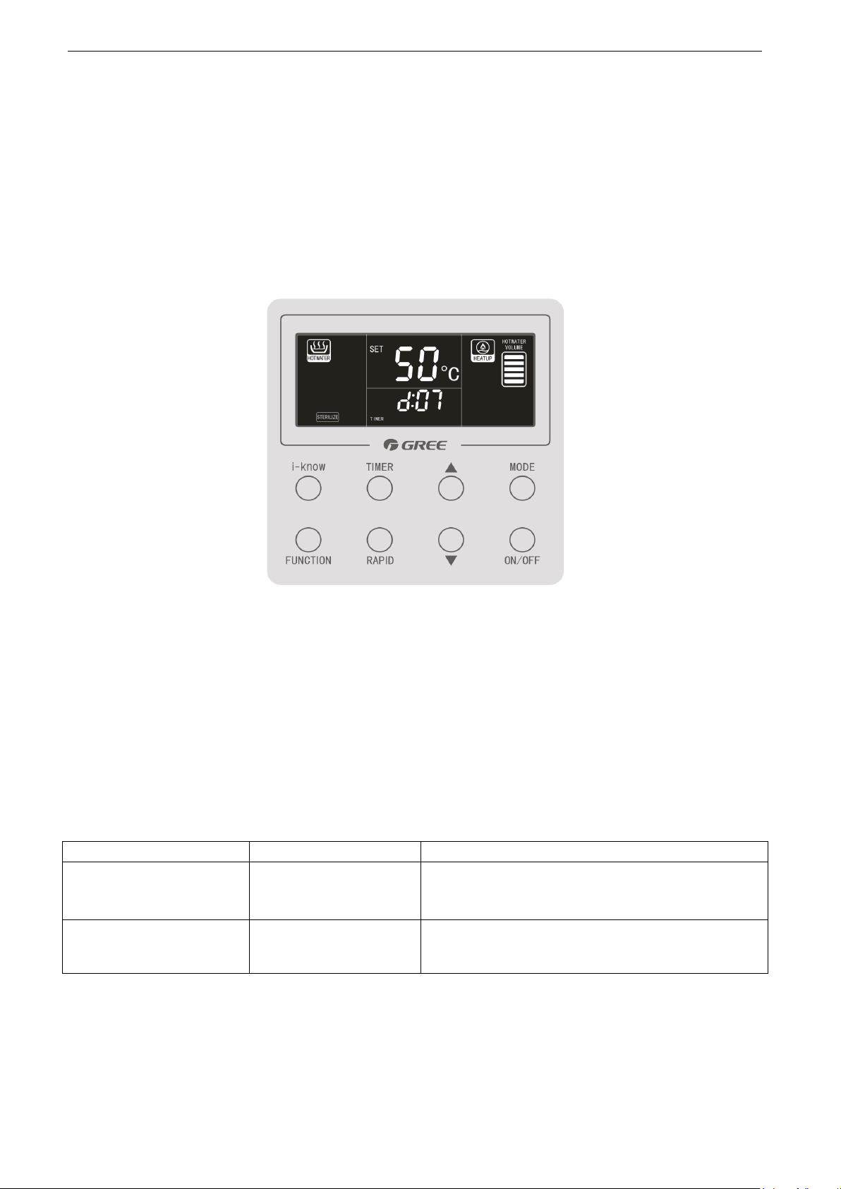
4.6.4 STERILIZE
The STERILIZE function is available under four common modes. However, after this function is set,
the unit runs as under the HOTWATER mode. The water heater controls startup and shutdown of the unit
based on the difference between the actual water temperature and that required for sterilization.
In the On state and in a common mode, press the FUNCTION button to enter the function selection
interface. When the STERILIZE function is selected, the corresponding icon blinks. At the same time, the
preset circular sterilization duration is displayed as d:XX, as shown in the following figure.
During this period, the following operations can be performed:
(1) Press ▲ or ▼ to start or cancel the STERILIZE function. If this function is started, the STERILIZE
icon is displayed without blinking. Sterilization will be performed circularly by the preset d and h value; If
this function is canceled, the STERILIZE icon is not displayed. If no operation is performed within 5s, it will
be regarded that this function is not required. After this function is started and when sterilization is being
performed, the function icon blinks.
(2) Press the TIMER button to enter the sterilization parameter setting interface. Press ▲ or ▼ to
select the d value and then press the TIMER button to confirm the value. When the confirmed d value is
not 0, the h value setting interface is displayed. Press ▲ or ▼ to select the h value and then press the
TIMER button to confirm the value. When the STERILIZE icon is displayed, the STERILIZE function is
started. If the STERILIZE icon blinks, the preset h value (time point for sterilization) is achieved and
sterilization is being performed.
Circular sterilization:
Sterilization is performed circularly by the d value. Once the circular sterilization conditions are met,
sterilization is performed regardless of on/off status of the controller and beyond limit of common modes
and functions except VACATION. However, users can stop sterilization under process by pressing the
ON/OFF button to shut it down. (But it can only stop sterilization for this time without affecting circular
19

GREE AIR SOURCE HEAT PUMP WATER HEATER SERVICE MANUAL
sterilization, the preset circular sterilization function still works.)
OFF reminder for sterilization failure:
If the OFF icon is displayed at the clock position after the STERILIZATION function is started,
sterilization fails and the water temperature required for sterilization cannot be reached. The OFF
reminder can be canceled when any button is pressed.
The OFF reminder only indicates that sterilization fails for this time without affecting circular
sterilization.
The OFF reminder is shown in the following figure.
Notes:
① When time goes from 23:59 to 00:00, the system enters a new day, which is the basis for increasing
the number of days.
② Every time after the STERILIZE function is started or sterilization parameters are adjusted in the
sterilize function setting interface, sterilization will be performed for once immediately and the day
interval for sterilization will be recalculated accumulatively. Even when sterilization is being
performed, operations such as sterilize function resetting and day interval adjusting for sterilization
will also cause recalculation of the day interval.
③ After the circular sterilization function is set, the water heater can still precisely calculate the day
interval for sterilization accumulatively and the circular sterilization function can still work in the case
of short-term power failure. If the time point for sterilization is within the power failure duration,
sterilization will be made up once power is provided again. In addition, the day interval for
sterilization will be recalculated accumulatively based on this sterilization and next sterilization will be
calculated accordingly.
④ Ensure that there is no long-term power failure; otherwise, the clock of the water heater will
malfunction and the STERILIZE function will not work properly.
⑤ Under the E-HEATER mode, the STERILIZE function is unavailable.
4.6.5 VACATION
In the On state, press the FUNCTION button to enter the function selection interface. When the
VACATION function is selected, the corresponding icon blinks. At the same time, the preset number of
vacation days is displayed at the clock position, as shown in the following figure.
20

GREE AIR SOURCE HEAT PUMP WATER HEATER SERVICE MANUAL
During this period, the following operations can be performed:
1) Press ▲ or ▼ to start or cancel the VACATION function. After this function is started, the
VACATION icon will be displayed without blinking and the water heater runs based on the preset number
of vacation days; If this function is canceled, the VACATION icon will not be displayed. If no operation is
performed within 5s, it will be regarded that this function is not required.
2) Press the TIMER button to set the number of vacation days. Press ▲ or ▼ to select the number
of vacation days from 3 to 120 days and press the TIMER button to confirm setting. Then press ▲ or ▼ to
start or cancel the VACATION function.
When the VACATION function is started under the On state, the water heater calculates the number
of vacation days accumulatively. And the STERILIZE function will be started to sterilize the water tank one
day before the vacation is over. In addition, hot water is prepared by advance in the HOTWATER before
the vacation is over.
Notes:
① When time goes from 23:59 to 00:00, the system enters a new day, which is the basis for increasing
the number of days.
② Every time after the VACATION function is started or the number of vacation days is adjusted in the
vacation function setting interface, the number of vacation days will be recalculated accumulatively.
Even when the VACATION function is being performed, operations such as vacation function
resetting and vacation day adjusting will also cause recalculation of the number of vacation days.
③ After the VACATION function is set, the water heater can still precisely calculate the number of
vacation days accumulatively in the case of short-term power failure. But ensure that there is no
long-term power failure; otherwise, the clock of the water heater will malfunction and the VACATION
function will not work properly.
4.7 Special Function
4.7.1 Keypad Lock
In normal status of the unit, press and hold ▲+▼ for 5s. The LOCK icon is displayed on the controller
and all buttons become unavailable. The LOCK icon blinks when any button is pressed. To cancel the
Keypad lock function, press and hold ▲+▼ for 5s again. Then the LOCK icon disappears.
If the unit is faulty, the lock function becomes invalid and all buttons are available again. The Keypad
lock function will resume after the error is rectified. In addition, the lock status before power failure is
memorized.
4.7.2 Temperature unit setting (℃/℉)
In the Off state of the wired controller, press and hold MODE+▲ on the main interface for 5s to enter
the query interface. Then the query code 00 is displayed, press and hold MODE+▲ for 5s to display the
21
GREE AIR SOURCE HEAT PUMP WATER HEATER SERVICE MANUAL
configurable parameter codes and values. Press ▲ or ▼ to select P5 and press the MODE button. Then
item value 00 or 01 blinks under the parameter code P5. Press ▲ or ▼ to select the item value and press
the MODE button to confirm setting (00: ℃ and 01: ℉). After that, press the FUNCTION button to return
to the main interface. If no operation is performed with 15s, it will switch back to the main interface
automatically.
Note: Other parameters cannot be modified; otherwise, operation exception will be caused.
4.8 Errors Display
When some errors occur during operation, the error codes will be displayed on the controller.
Meanwhile, the unit is in the Off state and the controller supports only the on/off and query functions.
If multiple errors occur to the water heater simultaneously, the corresponding error codes will be
displayed circularly.
If the controller displays a error, shut down the water heater and contact qualified personnel for
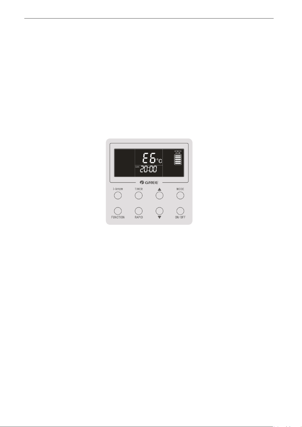
maintenance. The following figure shows a communication error.
For details on error codes, see the table attached at the end of this manual.
NOTES: Controller ZF5201 refer to the operational method ibidem.
22

GREE AIR SOURCE HEAT PUMP WATER HEATER SERVICE MANUAL
INSTALLATION
23
 Loading...