

Gree GMV-Pdhm224W/Na-M, GMV-Pdhm335W/Na-M, GMV-Pdhm400W/Na-M, GMV-Pdhm450W/Na-M, GMV-Pdhm504W2/Na-M Installation And Operating Instruction Manual
...
HEAT RECOVERY D.C INVERTER MULTI VRF
Installation and Operating Instruction Manual
This Manual is applicable to following outdoor units:
Basic Model:
GMV-Pdhm224W/Na-M GMV-Pdhm280W/Na-M
GMV-Pdhm335W/Na-M GMV-Pdhm400W/Na-M
GMV-Pdhm450W/Na-M
Combined Model:
GMV-Pdhm504W2/Na-M ~ GMV-Pdhm1800W4/Na-M
Please read this Manual carefully before
installation and use.
Thanks for your selection of Gree Air Conditioner Unit. Before use, please read this instruction
manual carefully and keep it properly to ensure correct use of this machine.
Instruction to Users 1
Safety Considerations 3
Selection of Installation Location and Precautions 8
Installation of Outdoor Unit 14
Connection of Indoor and Outdoor Units 25
Communication of the System 44
Notice for Project Installation 64
Installation Guideline for Air
Conditioner Unit
Filling of Refrigerants and Test Run 66
Operating Principle of Muti-split and Heat-recovered Air-Conditioning
Units
68
Types of Indoor Units to Be Integrated 70
Maintenance Measures 71
Reclaim refrigerants 72
Troubleshooting 75
Operating Temperature Range and Rated Work Conditions of the Unit
80
Performance Parameters of the Unit
81

1
Instruction to Users
☆ During using the unit under only-cooling /heating mode, the total capacity of indoor
units which are running simultaneously shouldn’t be more than that of outdoor unit,
or else poor cooling/heating capacity of each indoor unit will be resulted in. Under
principal-cooling /heating mode, the total capacity of indoor units as principal part
which are running simultaneously shouldn’t be more than that of outdoor units,or
else poor cooling /heating capacity of each indoor unit will be resulted in.
☆ According to capacity of each indoor unit, an air switch (or fuse) to each indoor unit
and a master switch to all indoor units should be installed. Each air switch, which is
usually shut off, is used for short circuit protection and abnormal overload of
corresponding indoor unit。The master switch is used for unified power supply for
all indoor units or shut-off of power supply.
☆ For smooth start of air conditioner unit, the main power switch shall be put to “ON”
position 8 hours before start.
☆ Upon receiving STOP signal from each indoor unit, the fan of related indoor unit will
continue to work for 20~70 seconds for purpose of utilizing the remaining cold air
or heats in heat exchanger and also make preparations for next use. This is normal.
☆ During installation, do not mix communication lines with power cables. Be sure to
separate them at minimum spacing over 20cm; otherwise it might result in
communication problem.
☆ If switch between cooling / dry mode and heating mode of indoor unit occurs or if
indoor unit is off under heating mode, brief flowing sound of refrigerants of cooling
and heating mode exchanger may occur ,which is normal.
☆ Install the cooling and heating mode exchanger in the place like corridor where
noise requirement is correspondingly lenient, furthermore, it should be installed in
ceiling with good sound insulation. Avoid installing it in the place like bedroom,
ward or office where low noise is required.
☆ An all-pole disconnection switch having a contact separation of at least 3mm in all
poles should be connected in fixed wiring

2
☆electric supply tolerances: (220-240V)±10%, (50±1)Hz
☆humidity :30-95%
☆installation altitude :max 1000m
☆transport/storage temperature : -25-55°C.
☆ Main switch provided by end user: main switch handle should be black or gray and it
can be locked in “OFF” position with padlock
☆ The main disconnection device should be explained in user manual and the height
should be recommended as 0.6-1.7m. Over current protection is required (EN
60947-3, EN 60947-2)
3
Safety Considerations
1. Please read this manual carefully before use and operate correctly as instructed in the manual.
2. You are specially warned to note the two symbols below.
WARNING!: A symbol indicates that improper operation might cause human death or severe
injuries.
CAUTIONS!: A symbol indicates that improper operation might cause human injury or
property damage.
WARNING!
z Please seek an authorized repair station for installation work. Improper installation might cause water
leakage, electric shock or fire.
z Please install at a place strong enough to support the weight of air conditioner unit. If not, the air
conditioner unit might fall down and cause human injury or death.
z To ensure proper drainage, the drainage pipe shall be correctly installed according to installation
instructions. Take proper measures for heat preservation to prevent condensing. Improper installation of
pipes might cause leakage and wet the articles in the room.
Do not use or store flammable, explosive, poisonous or other dangerous substances beside the air
conditioner.
z In case of trouble (e.g. burnt smell), please immediately cut off the main power of air conditioner unit.
z Keep air flow to avoid shortage of oxygen in the room.
z Never insert your finger or any objects into air outlet and inlet grill.
z Please take constant care to check if the mounting rack is damaged after long use.
z Never modify the air conditioner. Please contact the dealer or professional installation workers for repair
or relocation of the air conditioner.
4
Safety Considerations
Cautions!
z CAUTION FOR REFRIGERANT LEAKS
(Point to note connection with refrigerant leaks)
Introduction
The installer and system specialist shall safety against leakage according to local regulations or standards.
The following standards may be applicable if local regulations are not available. The GMV-Pdhm System
like other air conditioning system uses R410A as refrigerants.R410A itself is an entirely safe non-toxic,
non-combustible refrigerants. Nevertheless care must be taken to ensure that air conditioning facilities are
installed in a room which is sufficiently large. This assures that the maximum concentration level of
refrigerant gas is not exceeded, in the unlikely event of major leak in the system and this in accordance
with the local applicable regulations and standards.
Maximum concentration level
The maximum charge of refrigerants and the calculation of the maximum concentration of refrigerants is
directly related to the humanly occupied space in which it could leak.
The unit of measurement of the concentration is 1b/ft³(the weight in 1b of the refrigerant gas in 1 ft³
volume of the occupied space).
Compliance to the local applicable regulations and standards for the maximum allowable concentration
level is required.
1).Direction of the refrigerant flow
2).Room where refrigerants leak has occurred (outflow of the entire refrigerants from the system).
Pay a special attention to the place, such as a basement, etc. where refrigerant can stay, since refrigerant
is heavier than air.
Procedure for checking maximum concentration .Check the maximum concentration level in accordance
with steps 11 to 4 below and take whatever action is necessary to comply.
5
Safety Considerations
1. Calculate the amount of refrigerants (1b) charged to each system separately.
Amount of refrigerants in a single unit system (amount of refrigerant with which the system is charged
before leaving the factory)
+
Additional charging amount (amount of refrigerant added locally in accordance with the length or
diameter of the refrigerant piping)
=total amount of refrigerants (1b) in the system.
NOTE
Where a single refrigerant facility is divided into 2 entirely independent refrigerant systems then use
the amount of refrigerants with which each separate system is charged.
2. Calculate the smallest room volume(ft³)
Incase like the following, calculate the volume of (A), (B) as a single room or as the smallest room.
A. Where there are no smaller room divisions
B. Where there is a room division but there is an opening between the rooms sufficiently large to
permit a free flow of air back and forth.
6
Safety Considerations
1).opening between rooms.
2).partition.
(Where there is an opening without a door or where there are openings above and below the door which
are each equivalent in size to 0.15% or more of the floor area.)
3).Calculate the refrigerant density using the results of the calculations in steps 1 and 2 above.
Total volume of refrigerants in the refrigerant system ≤ maximum concentration level(1b/ ft³)
Size (ft³) of smallest room in which there is an indoor unit installed. If the result of the above
calculation exceeds the maximum concentration level then make similar calculations for the second
then third smallest room and so unit the result falls short of the second then third smallest room and
so until result falls short of the maximum concentration.
4).Dealing with the situations where the result exceeds the maximum concentration level and where the
installation of a facility encounters problem then it will be necessary to revise the system. Please consult
your GREE supplier.
z Before installation, please check the power supply for compliance with the ratings on nameplate. Check
the power safety as well. (it shall be done by professionals)
z Before use, please check and confirm if the cables, drainage pipes and pipelines are correctly
connected, hence to eliminate the risk of water leakage, refrigerants leakage, electric shock or fire(it
shall be done by professionals)
z Main power must be securely earthed to ensure effective grounding of air conditioner unit and avoid the
risk of electric shock. Please do not connect the earthing cable to coal gas pipe, water pipe, lightning
rod or telephone line.
z Once started, the air conditioner shall not be stopped at least after 10 minutes or longer; otherwise
service life of the unit will be affected.

7
Safety Considerations
z Do not let the child to operate the air conditioner unit.
z Do not operate the air conditioner unit with wet hands.
z Please disconnect the main power before cleaning the air conditioner or replacing the air filter.
z Please disconnect the main power if the air conditioner unit is out of use for a long period.
z This appliance is not intended for use by persons (including children) with reduced physical, sensory or
mental capabilities, or lack of experience and knowledge, unless they have been given supervision or
instruction concerning use of the appliance by a person responsible for their safety.
z Children should be supervised so that they can not play with the appliance.
z Please do not expose the air conditioner unit directly under corrosive environment with water or
moisture.
z Please do not put on or place any goods on air conditioner unit.
z After electrical installation, the air conditioner unit shall be energized for electrical leakage test. (it shall
be done by professionals)

8
Selection of Installation Location and Precautions
● Selection of Installation Location for Air Conditioner Unit
The installation of air conditioner unit must be in accordance with national and local safety
codes.
Installation quality will directly affect the normal use of air conditioner unit. The user is
prohibited from installation himself. Please contact your dealer after buying this machine.
Professional installation workers will provide installation and test services according to
installation manual.
Do not power on until all installation work is completed.
●
Selection of Installation Location for Indoor Unit
Avoid ☆ exposing in sunshine.
Ensure the hanger rod, ceiling and building structure have sufficient strength to support the weight of air ☆
conditioner unit.
☆ Drainage pipe is easy to connect out.
☆ Air inlet and outlet is not blocked.
Indoor and outdoor connection pipes are easy to go outdoors.☆
Do not install at a place where flammable or explosive goods exist or flammable or explosive gas might ☆
leak.
Do not install at a place☆ where there are corrosive gas, severe dust, salty fog, smoke or heavy moisture.
Select Installation Location of Outdoor Unit
Outdoor unit must be installed on a firm and solid support.☆
Outdoor unit shall be installed close to the indoor unit, hence to minimize the length ☆ and bends of cooling
pipe.
Avoid placing the outdoor unit under window or between two constructions, hence to prevent normal ☆
operating noise from entering the room.
Air flow at inlet and outlet shall not be blocked.☆
Install at a well☆ -ventilated place, so that the machine can absorb and discharge sufficient air.
Do not install at a place where flammable or explosive goods exist or a place ☆ where there are severe dust,
salty fog and polluted air.
Do not install induced draught pipe at the inlet and outlet of the outdoor unit. When the air
conditioner unit is generating heats indoors, the condensate water may flow from the base
of outdoor unit. When outdoor air is below 0 (32 ), the condensate water will be frozen. ℃℉
Take care that the installation of outdoor unit shall not affect the heat radiation of the unit.

9
Selection of Installation Location and Precautions
Caution!
Installation at following positions might cause trouble to the air conditioner unit. If unavoidable, please
contact Authorized Service Center.
A place full of machine oil; A region with saline①②-sodic soil near the sea;; A place with sulphide ③
gases (such as sulphur spring); A place with high frequency facilities, such as radio equipment, electric ④
welder or medical equipment;; An environment wi⑤ th special conditions.
● Cable Layout
Carry out installation in accordance with the state line layout rules. ☆
The power supply must be of rated voltage of the unit and special electrical line for air☆ -conditioning.
Please do not pull the ☆ power cord violently.
All electrical installation shall be carried out by professional technicians in accordance with the local laws ☆
and regulations.
The diameter of flexible power cable must be large enough; damaged flexible power cable and ☆
connection cable must be replaced by flexible cables for such special purpose.
☆ Ensure that safe grounding and the grounding wire shall be connected with the special grounding
equipment of the building and must be installed by professional technicians. In the fixed line there must
be an electrical leakage protection switch and an air switch with sufficient capacity (refer to the following
table). The air switch shall also have the magnetic tripping and thermal tripping functions to achieve
protection of both short-circuit and overload.

10
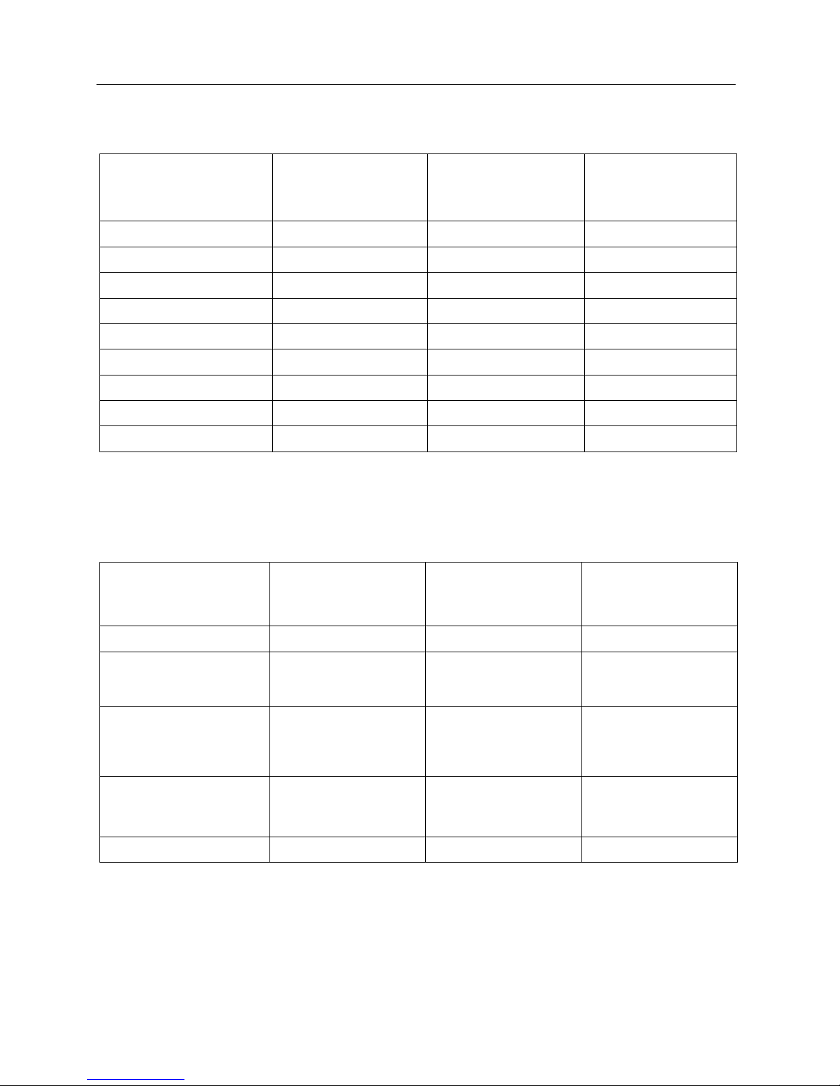
Selection of Installation Location and Precautions
Model
Power supply
(V,Ph,Hz)
Capability
of circuit
breaker
(A)
Min.
sectional
area of earth
lead (mm
2
)
Min.
sectional
area of
power cord
(mm
2
)
The number
of the
cord(N)
GMV-Pdhm224W/Na-M 380~415,3 ,50 32 6.0 6.0
5
GMV-Pdhm280W/Na-M 380~415,3 ,50 32 6.0 6.0
5
GMV-Pdhm335W/Na-M 380~415,3 ,50 40 10.0 10.0
5
GMV-Pdhm400W/Na-M 380~415,3 ,50 40 10.0 10.0
5
GMV-Pdhm450W/Na-M 380~415,3 ,50 40 10.0 10.0
5
GMV-Pdhm504W2/Na-M 380~415,3 ,50 63 25.0 25.0
5
GMV-Pdhm560W2/Na-M 380~415,3 ,50 63 25.0 25.0
5
GMV-Pdhm615W2/Na-M 380~415,3 ,50 80 35.0 35.0
5
GMV-Pdhm680W2/Na-M 380~415,3 ,50 80 35.0 35.0
5
GMV-Pdhm730W2/Na-M 380~415,3 ,50 80 35.0 35.0
5
GMV-Pdhm800W2/Na-M 380~415,3 ,50 80 35.0 35.0
5
GMV-Pdhm850W2/Na-M 380~415,3 ,50 80 35.0 35.0
5
GMV-Pdhm900W2/Na-M 380~415,3 ,50 80 35.0 35.0
5
GMV-Pdhm960W3/Na-M 380~415,3 ,50 100 50.0 50.0
5
GMV-Pdhm1010W3/Na-M 380~415,3 ,50 100 50.0 50.0
5
GMV-Pdhm1065W3/Na-M 380~415,3 ,50 125 70.0 70.0
5
GMV-Pdhm1130W3/Na-M 380~415,3 ,50 125 70.0 70.0
5
GMV-Pdhm1180W3/Na-M 380~415,3 ,50 125 70.0 70.0
5
GMV-Pdhm1250W3/Na-M 380~415,3 ,50 125 70.0 70.0
5
GMV-Pdhm1300W3/Na-M 380~415,3 ,50 125 70.0 70.0
5
GMV-Pdhm1350W3/Na-M 380~415,3 ,50 125 70.0 70.0
5
GMV-Pdhm1410W4/Na-M 380~415,3 ,50 160 95.0 95.0
5
GMV-Pdhm1460W4/Na-M 380~415,3 ,50 160 95.0 95.0
5
GMV-Pdhm1515W4/Na-M 380~415,3 ,50 160 95.0 95.0
5
GMV-Pdhm1580W4/Na-M 380~415,3 ,50 160 95.0 95.0
5
GMV-Pdhm1630W4/Na-M 380~415,3 ,50 160 95.0 95.0
5
GMV-Pdhm1700W4/Na-M 380~415,3 ,50 160 95.0 95.0
5
GMV-Pdhm1750W4/Na-M 380~415,3 ,50 160 95.0 95.0
5
GMV-Pdhm1800W4/Na-M 380~415,3 ,50 160 95.0 95.0
5
Note:The specification of power cord mentioned hereby is defined as the required specification when wiring
with BV single core cable (2 ~ 4 pieces) under the cover of PVC pipe, and environment temperature shall be
at 40℃; Air switch shall be selected according to 40℃ temperature condition, and shall in “D” type. if the
installation conditions on site change, please consider the modification on the required specification of
Power cord and Air switch, according to the specification manual provided by manufacture.
● Grounding Requirement
As air☆ -conditioning unit is of Class 1 electrical appliance, reliable grounding measures must be taken for
11
Selection of Installation Location and Precautions
it.
☆ The double color (yellow and green) cable inside the unit is specially used for grounding, so it shall not
be used for other purposes nor can it be cut. Do not tighten with tapping screws; otherwise it might cause
risk of electric shock.
Installation of earth resistance should be in accordance with local ☆ standards.
The user power supply shall have reliable grounding terminal. It is prohibited to connect the grounding wire
to the following items:
① Water Supply Pipe Gas Pipe Sewage Pipe L②③ ④ightning Rod or Earth Line of Phone Other ⑤
positions that are considered to be unreliable by professionals.
z Connection of power cord
Unit A
Power
Cabinet
Unit Unit
12
Selection of Installation Location and Precautions
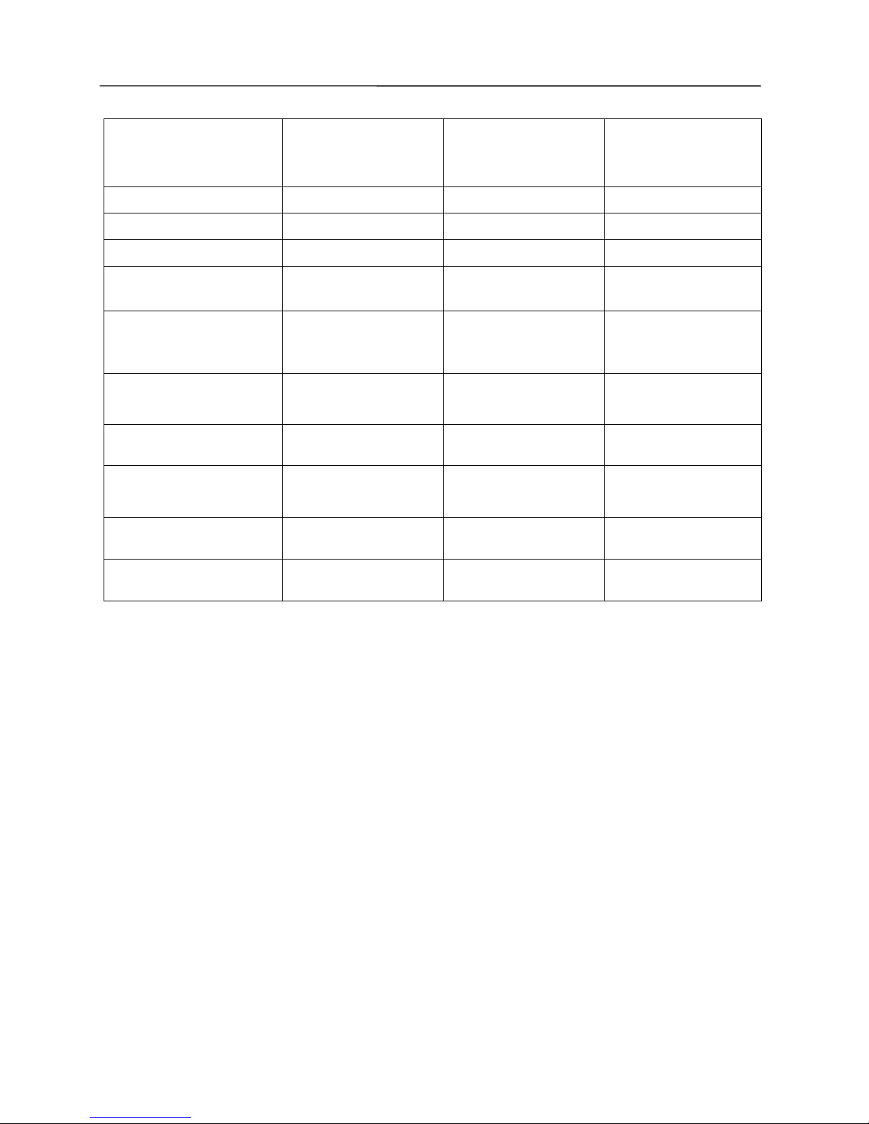
Power Supply Specification of Indoor Units
Sheet A: Circuit breakers below indicate total capacity of circuit breakers which are corresponding to indoor
units connecting general supply in the same system.
Total Capacity of the indoor
unit
Capacity of the Circuit
breaker
Min. Sectional Area of
Power Cord (mm
2
)
Min. Sectional Area of
Earth lead (mm
2
)
10A 以下
10 1.5 1.5
20~10A
20 4.0 4.0
32~20A
32 6.0 6.0
40~32A 40 10.0 10.0
50~40A 50 16.0 16.0
63~50A 63 35.0 16.0
80~63A 80 35.0 16.0
100~80A 100 50.0 25.0
125~100A 125 70.0 35.0
Note: Specific parameters can be revised according to conditions and laws of users’ country
Circuit breakers are closed in normal condition,which are for the purpose of short circuit protection for
indoor units and abnormal overload. All terminals of circuit breakers should be connected to a same
general supply switch for cutting power supply of all indoor units.
Indoor Unit Model
Capacity of the Circuit
breaker
Min. Sectional Area of
Earth lead (mm
2
)
Min. Sectional Area of
Power Cord (mm
2
)
Wall-mounted Units 10 1.0 1.0
Duct Type Units 10 1.0 1.0
Cassette Type Units( Heat
Pump or Cooling Only)
10 1.0 1.0
One-way Cassette Type units 10 1.0 1.0
Floor-standing Units 10 1.0 1.0
13
Selection of Installation Location and Precautions
If choose the indoor unit with auxiliary electric heater which decides the capacity of circuit breaker. Below is
the circuit breaker models which should be specially configured.
Model of Indoor Units(with
auxiliary electric)
Capacity of Circuit Breaker
Min. Sectional Area of
Earth lead (mm
2
)
Min. Sectional Area of
Power Cord (mm
2
)
22、28、32、36 duct type units
10 1.0 1.0
40、45、50duct type units
13 1.5 1.5
56、63、71、80duct type units
20 2.5 2.5
90、100、112、125、140 duct
type units
13 1.5 1.5
28、36、45、50 cassette type
units
10 1.0 1.0
56、63、71 cassette type units
13 1.5 1.5
80、90、112、125 cassette type
units
13 1.5 1.5
22、25、28、32、36 ultra-thin
duct units
10 1.0 1.0
40、45、50 ultra-thin duct units
13 1.5 1.5
56、63、71 ultra-thin duct units
16 2.5 2.5
●
Noise Control
Install ☆ the unit at a well-ventilated place; otherwise it might result in decreased working capacity or higher
noise.
Install ☆ the unit securely on a base that can fully support its weight; otherwise vibration and noise might be
caused.
Install the outdoor unit so that the hot air or noise will not disturb your neighb☆ ors.
Do not place any obstacle close the outlet of outdoor unit; otherwise it might result in decreased working ☆
capacity or higher noise.
If the air conditioner gives out abnormal noise during use, please immediately contact your dealer.☆
● Accessories for Installation Use
For the accessories for installation of indoor units and outdoor units, please see the Packing List in the
package.

14
Installation of Outdoor Unit
●
Precautions on Installation of Outdoor Unit
To ensure the unit in proper function, selection of installation location must be in accordance with following
principles:
Outdoor unit shall be installed so that the air discharged by outdoor unit will not return and that sufficient ☆
space for repair shall be provided around the machine.
Pla☆ ce of installation must be well ventilated so that the machine can absorb and discharge sufficient air.
Ensure the air inlet and outlet of the machine are not blocked. If blocked, please clear off the obstacles
blocking the air inlet or outlet.
Place of ☆ installation shall be strong enough to support the weight of outdoor unit, and it shall be able to
insulate noise and prevent vibration. Ensure that the wind and noise from the unit will not affect your
neighbors.
Outdoor unit must be lifted by using des☆ ignated lifting hole. Take care to protect the unit during lift. To
avoid rusting, do not knock the metal parts.
Try best to avoid direct sunshine.☆
Place of installation must be able to drain the rainwater and defrosting water.☆
Place of installation ☆ must ensure that the machine will not be buried under snow or subject to the
influence of rubbish or oil fog.
To meet the noise and vibration requirements, the outdoor unit shall be installed with rubber damper or ☆
spring damper.
☆
Installation dimension shall be in accordance with the installation requirements in this
manual. Outdoor unit must be securely fixed to the position.
The unit shall be installed by professional technicians.☆
● Installation of Outdoor Unit
1. Outline Dimension of GMV-Pdhm224W/Na-M、GMV-Pdhm280W/Na-M
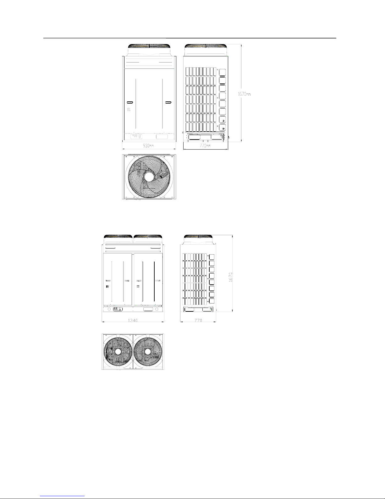
15
Installation of Outdoor Unit
Outline Dimension of GMV-Pdhm335W/Na-M、GMV-Pdhm400W/Na-M、GMV-Pdhm450W/Na-M
unit:mm
16
Installation of Outdoor Unit
2. Outdoor Unit Installation Holes of GMV-Pdhm224W/Na-M、GMV-Pdhm280W/Na-M
Outdoor Unit Installation Holes of GMV-Pdhm335W/Na-M、GMV-Pdhm400W/Na-M、GMV-Pdhm450W/Na-M
unit:mm
3.To handle the outdoor unit, enough length of two ropes must be used on four directions. To avoid
displacement of unit center, the angle of the ropes must be kept lower than 40
°
during lift and movement.
The below is illustration for lifting of GMV-Pdhm280W/Na-M outdoor unit, with which other outdoor unit
series with outlet on top is similar.
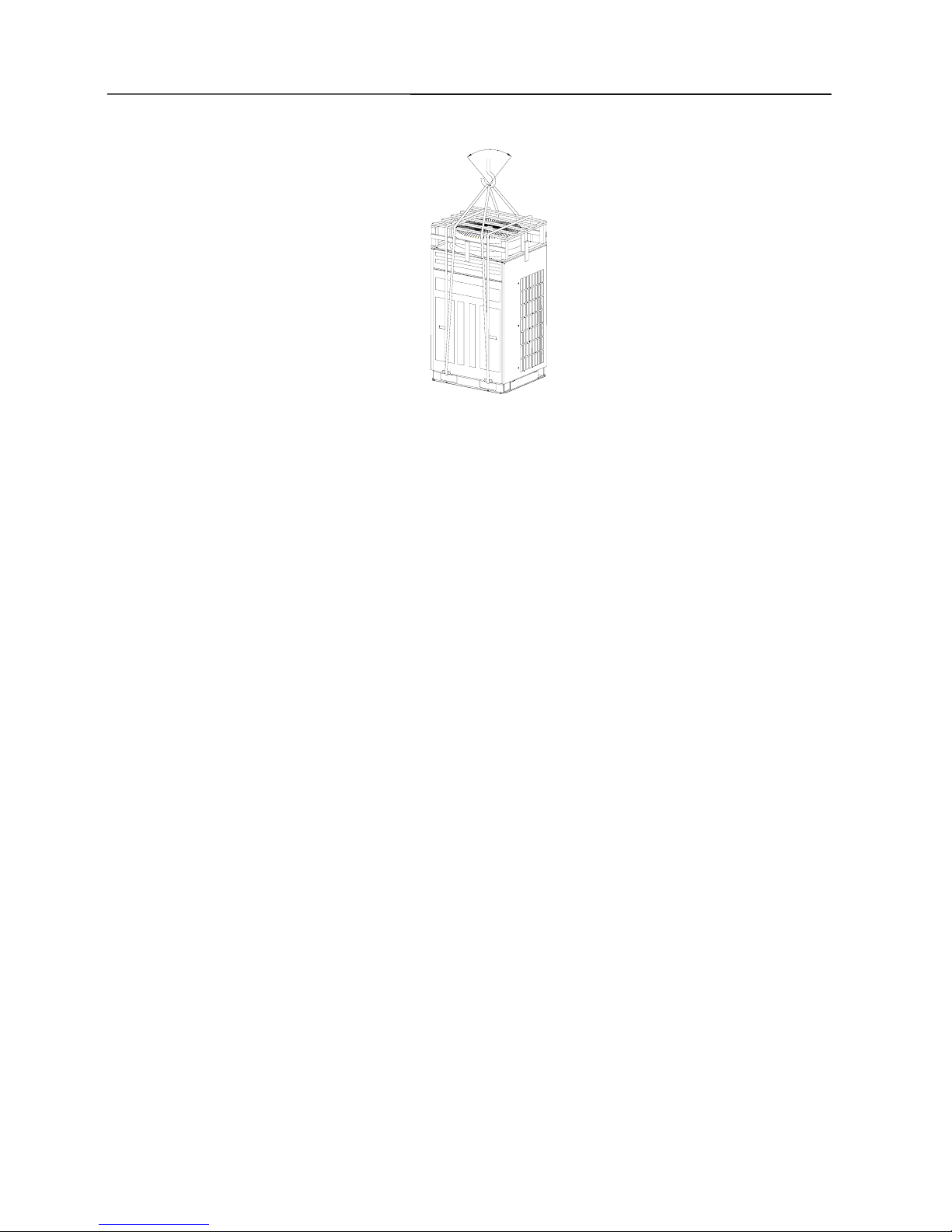
17
Installation of Outdoor Unit
<40°
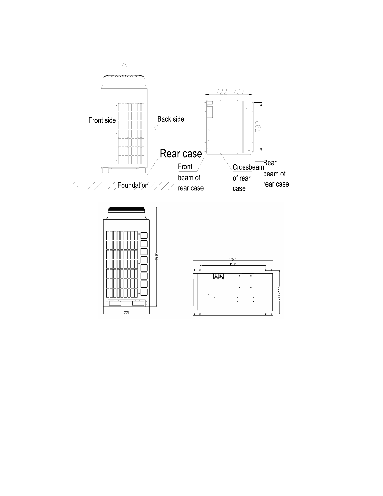
4. During installation, tighten the support and base of the unit by using M12 screws.
18
Installation of Outdoor Unit
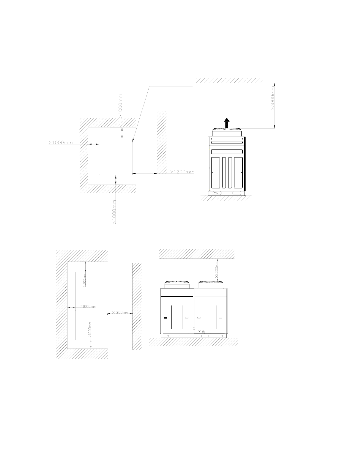
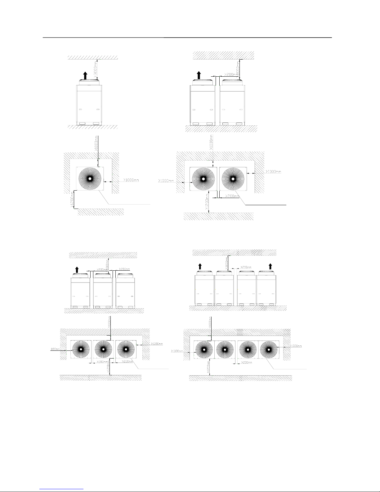
5. Space dimension for installation of the unit is shown below.
1) Clearance data of single unit
GMV-Pdhm224W/Na-M、GMV-Pdhm280W/Na-M
Outdoor
Unit
Electric box and exit are on this side
Air Outlet
GMV-Pdhm335W/Na-M、GMV-Pdhm400W/Na-M、GMV-Pdhm450W/Na-M
2) Clearance data of multiple unit
¾ Requirements for mounting space dimensions of single-fan and single-fan double-module outdoor units
19
Installation of Outdoor Unit
Air Outlet
Air Outlet
Electric box and exit are on this side
Electric box and exit are on this side
¾ Requirements for mounting space dimensions of single-fan three-module and double-fan double-module
outdoor units
出风口
Air Outlet
Air Outlet
Electric box and exit are on this side
Electric box and exit are on this side
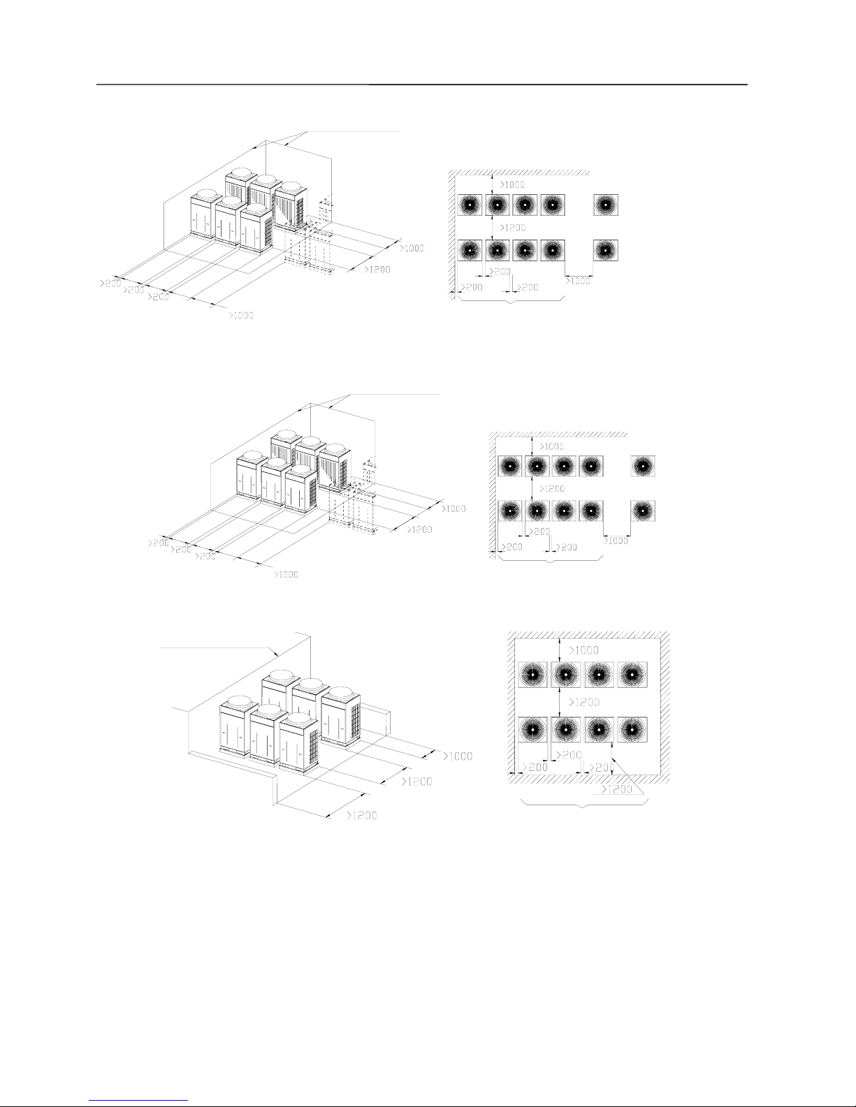
¾ Requirements for mounting space dimensions of double-fan three-module outdoor units
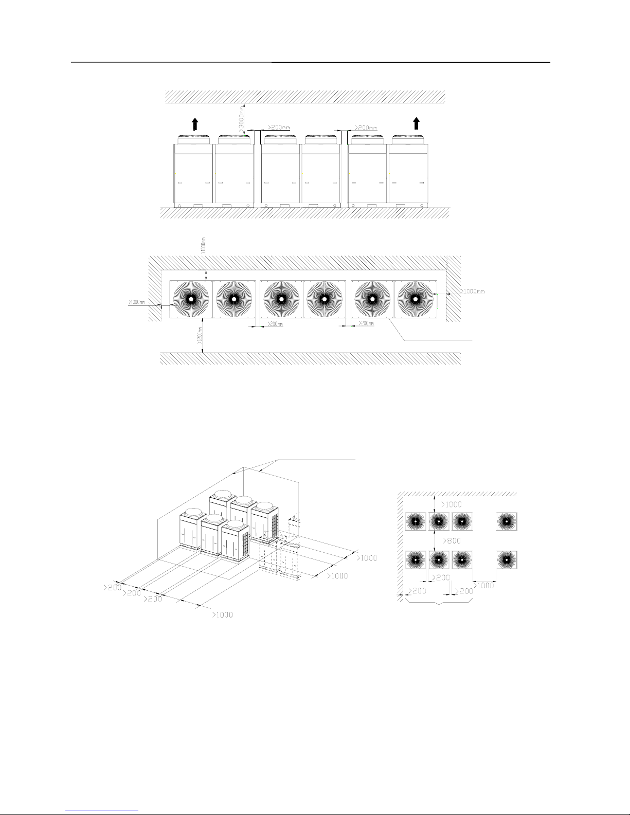
20
Installation of Outdoor Unit
Air Outlet
Air outlet
Electric box and exit are on this side
3).Take Monsoons and Snow into Consideration
To ensure good ventilation, the top of unit shall be kept open and free of any obstructions. In case that the
front side and left side (or right side) of the outdoor unit is open space, the unit shall be installed in the same
direction.
No restriction to wall height
ce to another outdoor unit beside
Max. three machines in line
Back side
Front side
Back side
Front side
Dimension of installation space for back-to-back installation is as below.
21
Installation of Outdoor Unit
Front side
Front side
Back side
Back side
No restriction to wall height
another outdoor unit beside
Max. four machines in line
In case there are walls on four sides of the outdoor unit,
it is suggested to install the unit in the same direction.
No restriction to wall height
to another outdoor unit beside
Max. Four machines in line
Front side
Back side
Back side
Front side
In case there are walls on four sides of the outdoor unit,
it is suggested to install the unit in the same direction.
前侧
后侧
前侧
后侧
Max. four machines in line
No restriction to wall height
4). The monsoon shall be taken into consideration when installing the outdoor unit.

22
Installation of Outdoor Unit
Correct
Fresh air suction side (back side)
Fresh air
suction side
(back side)
Protective
cover
Fresh air
suction side
(back side)
Fresh air
suction side
(back side)
Correct
Incorrect
The defrost time will be extended under this condition.
5). The snow shall be taken into consideration when installing the outdoor unit.
To prevent the snow from covering air supply outlet and air return inlet, it is required to use protective
covers on them, and use a higher foundation base.
Air supply
outlet protective
cover (to be
provided on
installation site)
)
Monsoon
Return air
protective cover
(to be provided
on installation
site)
The base height shall consider the snow.
Correct
Monsoon
Incorrect
6.Outdoor unit shall be installed on a concrete base with10cm height
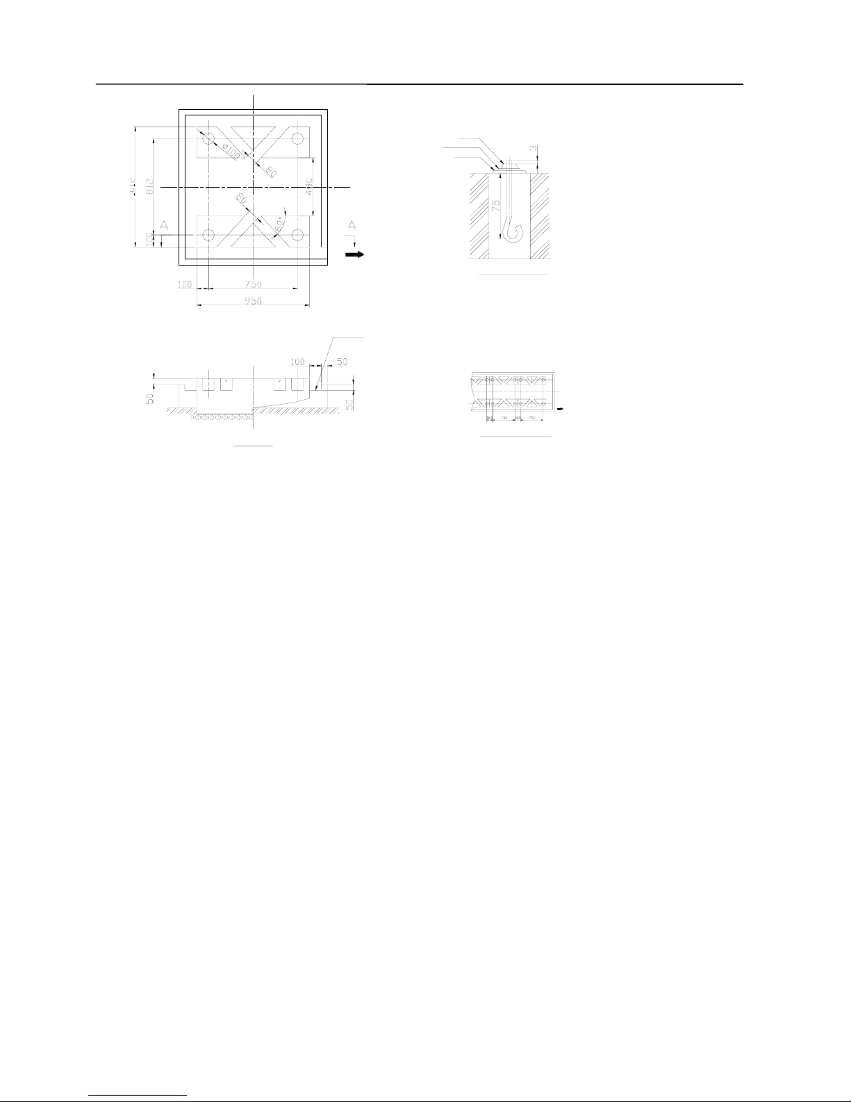
23
Installation of Outdoor Unit
型槽 型槽
Drainage ditch
Incline smoothly downward for 1/50 approx.
Construction method for anchoring bolt
Nut
Spring washer
Support
Screws protruding out
Type of anchoring bolt:JA
Size M12
4 bolts required
ilt on ground
When foundation is built on floor
Drainage ditch
A Viewa
Centralized Installation of Multiple Units
Notes:
1) Concrete proportioning: Cement: sand: stone = 1: 2: 4. Meanwhile, 10 pieces of φ10mm reinforced
steel bars shall be placed every 30mm.
2) Level the foundation surface with mortar and chamfer the sharp edge.
3) It is not needed to use gravel stone when the foundation is built on concrete floor, but the foundation
surface must be deburred.
4) Drainage ditch shall be built around the foundation, so that the condensate from the equipment can be
fully discharged.
5) To install the air conditioner on roof, please check the strength of building and take waterproof
measures.

24
Installation of Outdoor Unit
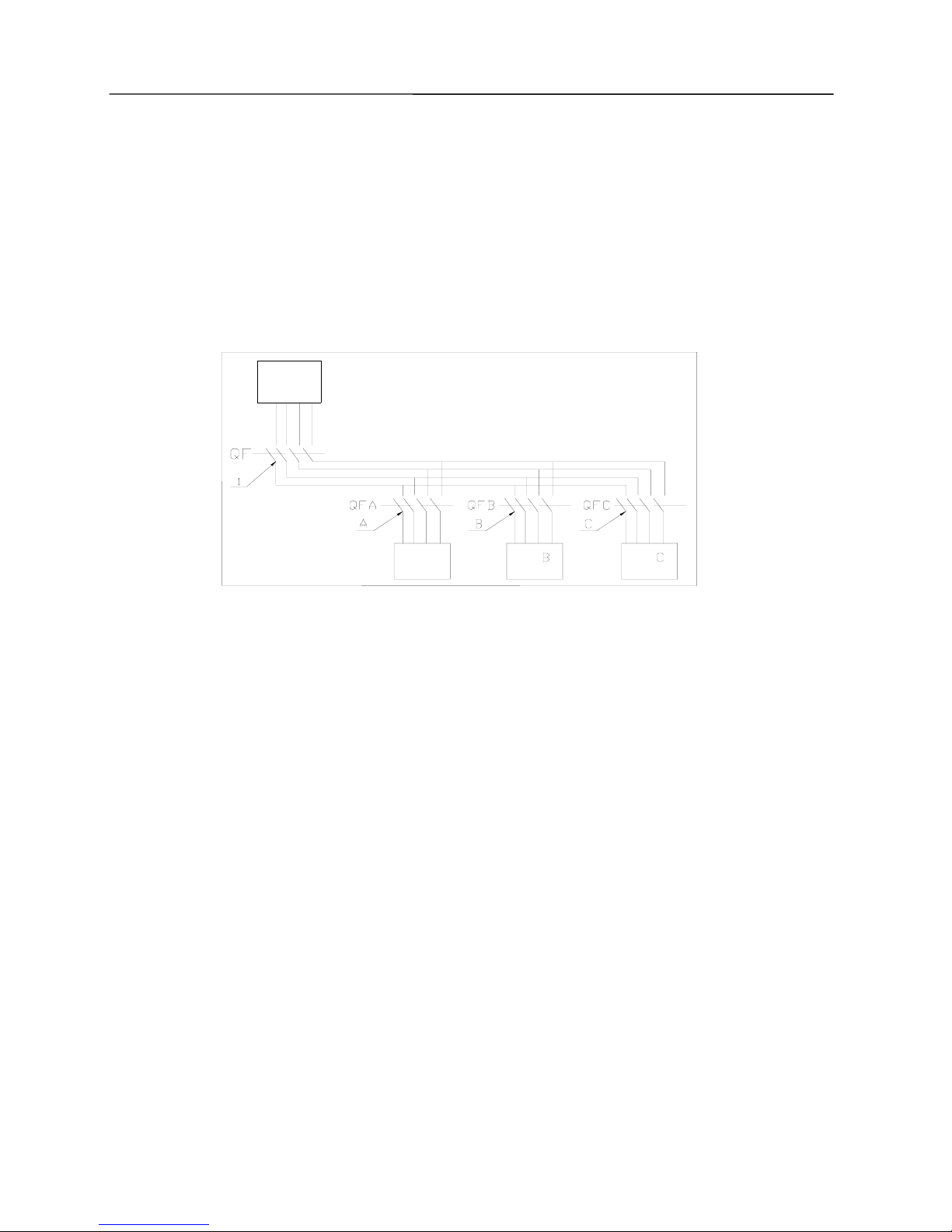
●Electrical Cable Connection
Cautions:
☆ Outdoor unit and indoor unit may be of unified power supply or separate power supply. But the
indoor units must be of unified power supply.
☆ Be sure install a circuit breaker that can cut off the power of complete system.
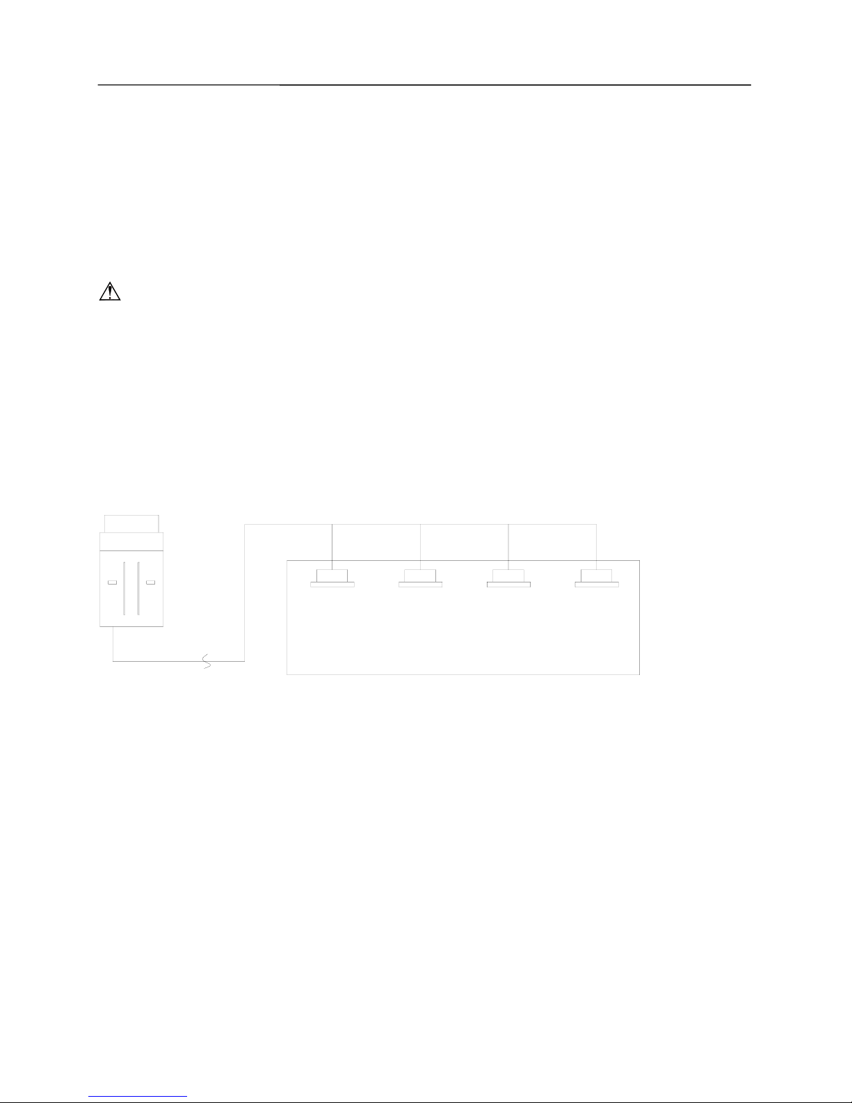
● Power Cable Connection:
1. Pass the cable though rubber ring.
2. Connect the power cable
with the terminal marked “L1, L2, L3 & N” and earthing screws.
3. Fix the cables with cable clamp.
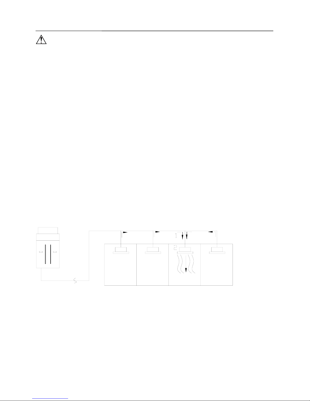
● Connection of Distribution (Communication) Line:
1. Open the electric box on outdoor unit.
2. Pass the distribution (communication) line into the base and through the rubber ring of electrical box.
3. Insert the distribution (communication) line into 4-pin terminal CN11 on outdoor unit circuit board.
4. Fix the distribution (communication) lines properly.
5. Put back the junction cover plate and tighten the screws. Cover up the panel.
25
Connection of Indoor and Outdoor Unit
●Installation requirements of refrigerant piping
1. Specification of Connecting Pipes
R410A refrigerant system
External
Diameter(mm/inch)
Thickness(mm) Type
Φ6.35(1/4)
≥0.8
0
Φ9.52(3/8)
≥0.8
0
Φ12.70(1/2)
≥0.8
0
Φ15.88(5/8)
≥1
0
Φ19.05(3/4)
≥1
1/2H
Φ22.2(7/8)
≥1.5
1/2H
Φ25.40(1/1)
≥1.5
1/2H
Φ28.60(9/8)
≥1.5
1/2H
Φ34.90(11/8)
≥1.5
1/2H
Φ38.10(12/8)
≥1.5
1/2H
Φ41.30(13/8)
≥1.5
1/2H
Φ44.45(7/4)
≥1.5
1/2H
Φ54.1(17/8)
≥1.5
1/2H
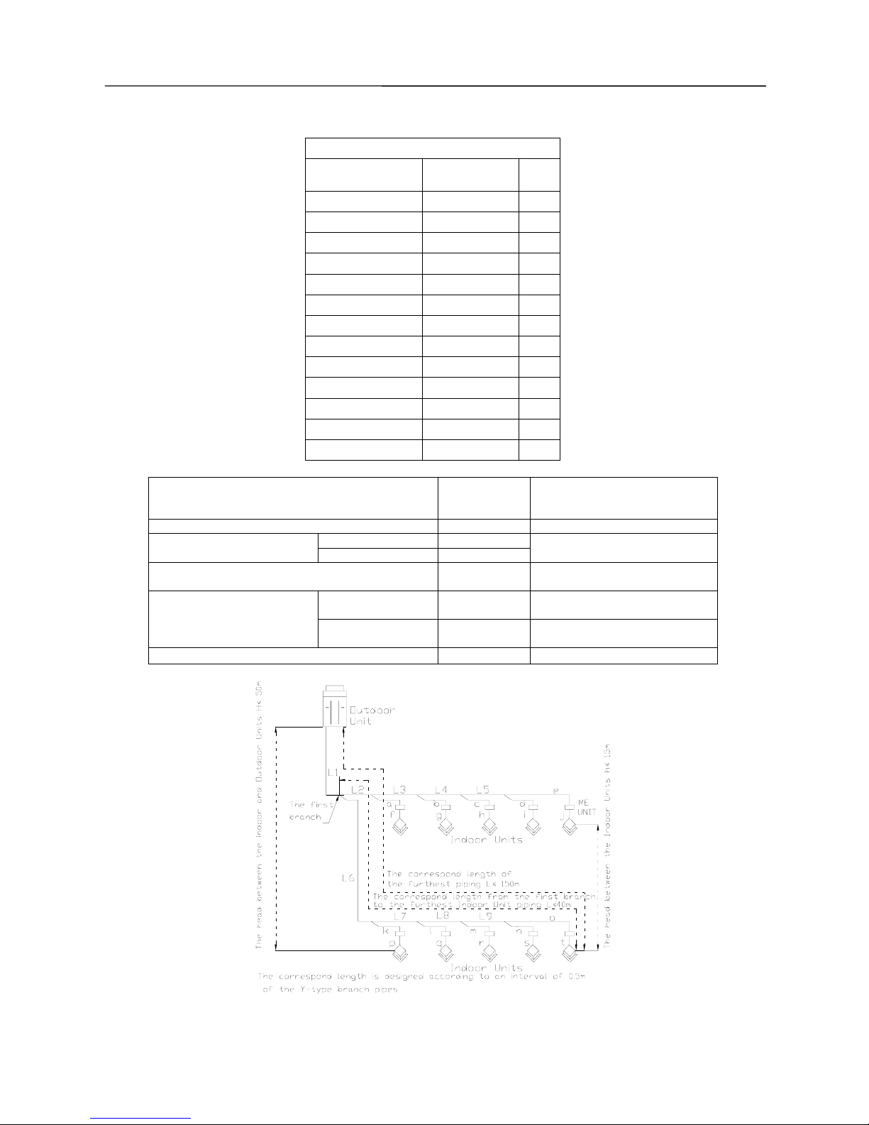
2. Allowable Length and Height Differences of the Connecting pipes between the Indoor and Outdoor Units
R410A refrigerant system
Allowable
(m/ft)
value
Fitting pipe
Total length (actual length) of fitting pipe 500/1640 L1+L2+L3+L4+…+L9+a+b+…+s+t
Actual length 150/492 Length of the furthest fitting
pipe
Equivalent length 175/574
L
1+L6+L7+L8+L9
+o+t
Equivalent length of fitting pipe
from the 1
st
branch joint to farthest indoor unit
40/131.2 L
1+L6+L7+L8+L9
+o+t
Outdoor unit at
upper
50/164
——
Height differences between
indoor unit and outdoor unit
Outdoor unit at
lower
40/131.2
——
Height differences between indoor units 15/49.2 ——
26
Connection of Indoor and Outdoor Unit
3. Selection of Diameter of Branch Pipe and Connection Pipe
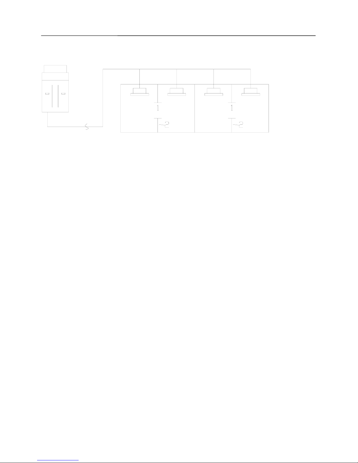
System Piping Schematics:
1). Selection of the branch piping between outdoor units
R410A refrigerant
system
Total Capacity of the Outdoor Unit
(C)
Model
224≤C≤960
ML01R
Y-Type Branch Pipe
960<C
ML02R
Piping between connection sub-assys of module
Piping between outdoor unit and indoor unit
Piping between outdoor unit and connection sub-assy
Piping between outdoor unit and connection sub-assy
Connection pipes between the branch
piping of outdoor unit and indoor unit
Connection branch piping
between outdoor units
Connection piping between
branch
pip
es of outdoor units
Branch piping
between indoor units
Connection pipe between the branch piping of outdoor
unit and the first branch pipe on the indoor side
Connecting pipe between the branch piping
of indoor unit and mode exchange
r
Indoor Unit 1
Connecting pipe between the
branch pipes of outdoor unit
Connecting pipe between the branch
piping
of indoor unit and mode converte
r
Indoor Unit 2
Connecting pipe between the branch
piping
of indoor unit and mode converte
r
Connecting pipe between the
branch pipes of outdoor unit
Indoor Unit 3
Connecting pipe between the
branch pipes of outdoor unit
27
Connection of Indoor and Outdoor Unit
The diameter of the piping (the main pipe) from the Outdoor Unit to the first branch joint
A. For a single-module system, the diameter of the piping from the Outdoor Unit to the first branch joint shall
be selected according to the diameter of refrigerant piping for outdoor unit. The diameter of connection pipes
for basic module outdoor unit is as below:
Piping Connections
Basic Model
Liquid
(mm)
Suction Gas
(mm)
Discharge Gas
(mm)
GMV-Pdhm224W/Na-M
Φ9.5 Φ22.2 Φ19.1
GMV-Pdhm280W/Na-M
Φ9.5 Φ22.2 Φ19.1
GMV-Pdhm335W/Na-M
Φ12.7 Φ28.6 Φ19.1
GMV-Pdhm400W/Na-M Φ12.7 Φ28.6 Φ22.2
GMV-Pdhm450W/Na-M Φ12.7 Φ28.6 Φ22.2
B. If it is multi-module system,
The diameter of the branch piping between modules and outdoor unit shall be selected based on the
diameter of the connection pipe of basic module outdoor unit. The diameter of the connection pipe of basic
module outdoor unit is as below:
Piping Connections
Basic Model
Lquid
pipe
(mm)
Low-pressure
gas pipe
(mm)
High-pressure
gas pipe
(mm)
GMV-Pdhm224W/Na-M
Φ9.5 Φ22.2 Φ19.1
GMV-Pdhm280W/Na-M
Φ9.5 Φ22.2 Φ19.1
GMV-Pdhm335W/Na-M
Φ12.7 Φ28.6 Φ19.1
GMV-Pdhm400W/Na-M Φ12.7 Φ28.6 Φ22.2
GMV-Pdhm450W/Na-M Φ12.7 Φ28.6 Φ22.2
The diameter of the connection pipe between the branch pipes of basic module outdoor unit is as follows:
Diameter of the refrigerant piping between the branch
pipes of outdoor unit
Lquid pipe
(mm)
High-pressur
e gas pipe
(mm)
Low-pressur
e gas pipe
(mm)
450≥Q Φ12.7 Φ28.6 Φ28.6
960≥Q>
450
Φ19.1 Φ34.9 Φ34.9
1580≥Q>
960
Φ22.2 Φ41.3 Φ41.3
Total rated
capacity Q
of upstream
outdoor unit
Q>1580 Φ25.4 Φ41.3 Φ54.1
 Loading...