

Gree GMV-NDX48P/A-T, GMV-NDX54P/A-T, GMV-NDX42P/A-U, GMV-NDX48P/A-U, GMV-NDX96P/A-T Owner's Manual
...
Owner's Manual
Original Instructions
Commercial Air Conditioners
Multi Variable Air Conditioners
Fresh Air Series Indoor Unit
Models:
GMV-NDX42P/A-T(U)
GMV-NDX48P/A-T(U)
GMV-NDX54P/A-T(U)
GMV-NDX72P/A-T(U)
GMV-NDX96P/A-T(U)
Preface
For correct installation and operation, please read all instructions carefully. Before
reading the instructions, please be aware of the following items:
This is the safety alert symbol. It is used to alert you to potential personal injury hazards.
Obey all safety messages that follow this symbol to avoid possible
injury or death.
This mark indicates procedures which, if improperly performed, might lead to the death or
serious injury of the user.
This mark indicates procedures which, if improperly performed, might possibly result in
personal harm to the user, or damage to property.
NOTICE is used to address practices not related to personal injury.
Instructions for installation and use of this product are provided by the manufacturer.
(1) Installation must be performed in accordance with the requirements of NEC and CEC by authorized
personnel only.
(2) For safety operation, please strictly follow the instructions in this manual.
(3) During operation, the gross rated capacity of working IDU should be within the gross rated capacity of
ODU. Otherwise, IDU’s cooling/heating performance will be reduced.
(4) This manual must be in the hands of direct operators or maintenance men.
(5) In case of malfunction and operation failure, please examine the following items and contact our
authorized service centers as soon as possible.
Nameplate (model, cooling capacity, product code, ex-factory date).
Malfunction status (detail description of conditions before and after malfunction occurs)
(6) All units have been strictly tested and proved to be qualified before ex-factory. To avoid unit damage or
even operation failure which may be caused by improper disassembly, please do not disassemble units
by yourself. If disassembly is needed, please contact our authorized serve centers for help.
(7) All graphics and information in this manual are only for reference. Manufacturer reserves the right for
changes in terms of sales or production at any time and without prior notice.
(8) If the supply cord is damaged, it must be replaced by the manufacturer, its service agent or similarly
qualified persons in order to avoid a hazard.
This appliance can be used by children aged from 8 years and above and persons
with reduced physical, sensory or mental capabilities or lack of experience and knowledge
if they have been given supervision or instruction concerning use of the appliance in a safe
way and understand the hazards involved. Children shall not play with the appliance.
Cleaning and user maintenance shall not be made by children without supervision.
GWP:410A:2087.5
DISPOSAL: Do not dispose this product as unsorted municipal waste.
Collection of such waste separately for special treatment is necessary.

Contents
1 Safety Precautions .................................................................................................. 1
2 Product Introduction ................................................................................................ 2
2.1 Unit Introduction ........................................................................................................... 2
2.2 Rated Working Condition ............................................................................................. 3
2.3 Working Temperature Range ........................................................................................ 3
3 Preparations for Installation ..................................................................................... 4
3.1 Standard Fittings .......................................................................................................... 4
3.2 Location for Installation ................................................................................................ 5
3.3 Requirements for Communication Line ........................................................................ 6
3.4 Wiring Requirements .................................................................................................... 7
4 Installation Instructions ............................................................................................ 8
4.1 Installation of Indoor Unit .............................................................................................. 8
4.2 Pipe Connection .......................................................................................................... 11
4.3 Installation and Test of Drain Pipe ...............................................................................12
4.4 Installation of Air Duct .................................................................................................15
4.5 Installation of Wired Controller ....................................................................................17
5 Wiring Work ................................................................................................ ........... 17
5.1 Connection of Wire and Patch Board Terminal ............................................................18
5.2 Power Cord Connection .............................................................................................. 18
5.3 Connection of Communication Line of IDU and ODU ..................................................19
5.4 Connect Communication Wire of Wired Controller ......................................................19
5.5 Illuminate for Connection of Wired Controller and Indoor Units Network .....................20
6 Routine Maintenance ............................................................................................. 22
6.1 Cleaning of Filter .........................................................................................................22
6.2 Maintenance before the Seasonal Use ........................................................................22
6.3 Maintenance after the Seasonal Use ...........................................................................22
7 Table of Error Codes for Indoor Unit ...................................................................... 23
8 Troubleshooting ..................................................................................................... 24
Multi Variable Air Conditioners Fresh Air Series Indoor Unit
1
1 Safety Precautions
(1) Follow this instruction to complete the installation work. Please carefully read this manual before unit startup
and service.
(2) Wire size of power cord should be large enough. The damaged power cord and connection wire should be
replaced by exclusive cable.
(3) After connecting the power cord, please fix the electric box cover properly in order to avoid accident.
(4) Never fail to comply with the nitrigen charge requirements. Charge nitrogen when welding pipes.
(5) Never short-circiut or cancel the pressure switch to prevent unit damage.
(6) Please firstly connect the wired controller before energization, otherwise wired controller cannot be used.
(7) Before using the unit, please check if the piping and wiring are correct to avoid water leakage, refrigerant
leakage, electric shock, or fire etc..
(8) Do not insert fingers or objects into air outlet/inlet grille.
(9) Open the door and window and keep good ventilation in the room to avoid oxygen deficit when the gas/oil
supplied heating equipment is used.
(10) Never start up or shut off the air conditioner by means of directly plug or unplug the power cord.
(11) Turn off the unit after it runs at least five minutes; otherwise it will influence oil return of the compressor.
(12) Do not allow children operate this unit.
(13) Do not operate this unit with wet hands.
(14) Turn off the unit or cut off the power supply before cleaning the unit, otherwise electric shock or injury may
happen.
(15) Never spray or flush water towards unit, otherwise malfunction or electric shock may happen.
(16) Do not expose the unit to the moist or corrosive circumstances.
(17) Under cooling mode, please don't set the room temperature too low and keep the temperature difference
between indoor and outdoor unit within 5ºC(41ºF).
(18) User is not allowed to repair the unit. Fault service may cause electric shock or fire accidents. Please
contact Gree appointed service center for help.
(19) Before installation, please check if the power supply is in accordance with the requirements specified on the
nameplate. And also take care of the power safety.
(20) Installation should be conducted by dealer or qualified personnel. Please do not attempt to install the unit by
yourself. Improper handling may result in water leakage, electric shock or fire disaster etc..
(21) Be sure to use the exclusive accessory and part to prevent the water leakage, electric shock and fire
accidents.
(22) Make sure the unit can be earthed properly and soundly after plugging into the socket so as to avoid electric
shock. Please do not connect the ground wire to gas pipe, water pipe, lightning rod or telephone line.
(23) Electrify the unit 8 hours before operation. Please switch on for 8 hours before operation. Do not cut off the
power when 24 hours short-time halting (to protect the compressor).
(24) If refrigerant leakage happens during installation, please ventilate immediately. Poisonous gas will emerge if
the refrigerant gas meets fire.

Multi Variable Air Conditioners Fresh Air Series Indoor Unit
2
(25) Volatile liquid, such as diluent or gas will damage the unit appearance. Only use soft cloth with a little neutral
detergent to clean the outer casing of unit.
(26) If anything abnormal happens (such as burning smell), please power off the unit and cut off the main power
supply, and then immediately contact Gree appointed service center. If abnormality keeps going, the unit
might be damaged and lead to electric shock or fire.
GREE will not assume responsibility of personal injury or equipment damage caused
by improper installation and commission, unnecessary service and incapable of following
the rules and instructions listed in this manual.
2 Product Introduction
2.1 Unit Introduction
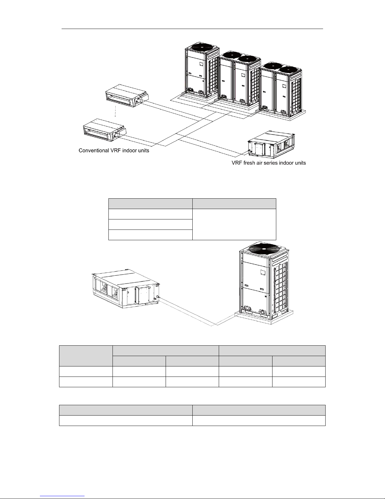
VRF fresh air series indoor unit is a kind of air processing unit that inhales the fresh air
from outdoor side and then processes it to provide for the user in the room. According to
the different selected air volume, there are two kinds of connection method for the VRF
fresh air series indoor unit:
(1) If the selected air volume ≤1471 CFM, connect with normal indoor units by blow
method, or connect with the fixed outdoor unit as shown in (2).
Model of Indoor Unit
Model of Outdoor Unit
GMV-NDX42P/A-T(U)
Connecting condition with GMV-**WM/B-F(U) series modular outdoor unit:
The total capacity of connected fresh air series indoor units and conventional
VRF indoor units must be within 50%~100% of the capacity of outdoor unit,
among which, the total capacity of connected fresh air indoor units cannot
exceed 30% of the capacity of outdoor unit.
GMV-NDX48P/A-T(U)
GMV-NDX54P/A-T(U)
GMV-NDX72P/A-T(U)
GMV-NDX96P/A-T(U)
NOTICE!
When fresh air series indoor units and conventional VRF indoor units will be
connected, please follow the capacity requirement strictly. The total capacity of connected
fresh air indoor units cannot exceed 30% of the capacity of outdoor unit, while the total
capacity of indoor units shall be within 50%~100% of the capacity of outdoor unit.
Otherwise, the comfortableness will be affected or even the unit will be damaged.
Multi Variable Air Conditioners Fresh Air Series Indoor Unit
3
Connection diagram of fresh air series indoor units and conventional VRF indoor units
(2) If the selected air volume >1471 CFM, it can only connect the fixed outdoor unit
as below:
Model of Indoor Unit
Model of Outdoor Unit
GMV-NDX54P/A-T(U)
GMV-72WM/B-F(U)
GMV-NDX72P/A-T(U)
GMV-NDX96P/A-T(U)
2.2 Rated Working Condition
Indoor Side Condition
Outdoor Side Condition
Dry Bulb Temp
Wet Bulb Temp
Dry Bulb Temp
Wet Bulb Temp
Rated Cooling
35°C(95°F)
28°C(82°F)
35°C(95°F)
28°C(82°F)
Rated Heating
7°C(45°F)
6°C(43°F)
7°C(45°F)
6°C(43°F)
2.3 Working Temperature Range
Outdoor Ambient Dry Bulb
Working Temperature Range
-7°C~45°C (19°F~113°F)
NOTICE!
The ex-factory set temperature is 18°C (64°F) in cooling mode and 22°C
(72°F) in heating mode. If the user needs to change the temperature setting, please
contact after-sales service personnel.
Multi Variable Air Conditioners Fresh Air Series Indoor Unit
4
3 Preparations for Installation
NOTICE!
Product graphics are only for reference. Please refer to actual products.
Unspecified measure unit is mm(in.).
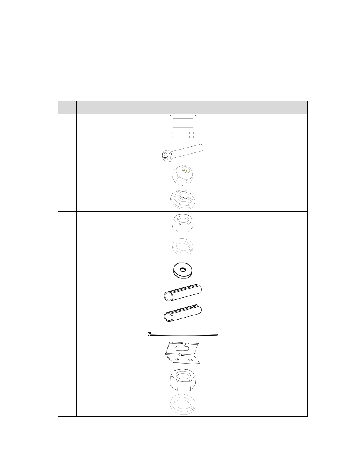
3.1 Standard Fittings
Please use the supplied standard fittings listed below as instructed.
No.
Name
Graphics
Quantity
Function
1
Wired Controller
1PC
To control the indoor
unit
2
M4X25 Screw
(Cross recessed small pan
head screw)
2 PC
To fix the wired
controller
3
Union Nut Sub-assy
1 Set
To be used for
connecting the
refrigerant pipe
4
M10 Nut (Nut with Washer
M10X8)
4 PC
To be used together
with the hanger bolt for
installing the unit.
5
M10 Nut (M10X8.4)
8 PC
To be used together
with the hanger bolt for
installing the unit.
6
M10 Washer
(Spring Washer M10X2.6)
4 PC
To be used together
with the hanger bolt for
installing the unit.
7
M10 Washer
(M10XΦ30X 2.5)
4 PC
To be used together
with the hanger bolt for
installing the unit.
8
Insulation
1 PC
To insulate the gas
pipe
9
Insulation
1 PC
To insulate the liquid
pipe
10
Fastener
8 PC
To fasten the sponge
11
Hanger
4 PC
To fix the indoor unit
12
M8 Nut (M8X6.8)
8 PC
To fix the hook on the
cabinet of the unit.
13
M8 Washer
(Spring Washer M8X2.1)
8 PC
To fix the hook on the
cabinet of the unit.
Multi Variable Air Conditioners Fresh Air Series Indoor Unit
5
14
M8 Washer
(M8XΦ16X 1.5)
8 PC
To fix the hook on the
cabinet of the unit.
15
Sponge of Drain Pipe
2 PC
Wrap the joint of drain
pipe
NOTICE!
The fittings list above is subject to change without notice, please refer to the
packing list provided with indoor unit.
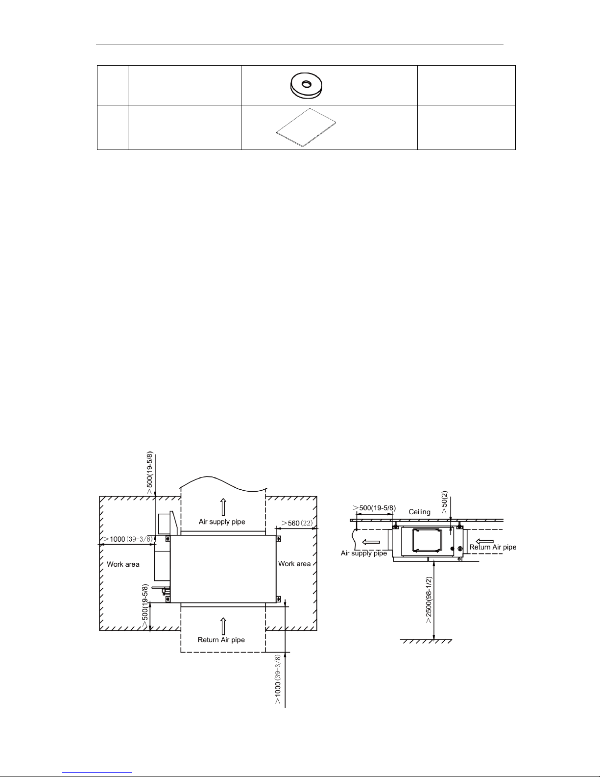
3.2 Location for Installation
(1) Appliances are not accessible to the general public.
(2) The top holder must be strong enough to support unit's weight.
(3) Drain pipe can drain water out easily.
(4) There is no obstacle at inlet or outlet. Please ensure good air circulation.
(5) In order to make sure the space for maintenance, please install the indoor unit
according to the dimension described below.
(6) Keep the unit away from heat source, inflammable gas or smoke.
(7) This is a concealed ceiling type unit.
(8) This series indoor unit can be allowed to supply air for only one room.
(9) Indoor unit, outdoor unit, power cord and electric wire should stay at least 1m
(3-1/4ft.) from the TV set and radio. Otherwise, these electric appliances may
have image interference and noise. (Even if the distance is 1m (3-1/4ft.), when
there is strong electric wave, noise may still occur.)
Unit: mm (in.)
Multi Variable Air Conditioners Fresh Air Series Indoor Unit
6
(1) Install the unit at a place where is adequate to withstand the weight of the unit and make sure the unit would
not shake or fall off.
(2) Never expose the unit under direct sunshine and rainfall. Install the unit at a place where is against dust,
typhoon and earthquake.
(3) Try to keep the unit away from combustible, inflammable and corrosive gas or exhaust gas.
(4) Leave some space for heat exchanging and servicing so as to guarantee unit normal operation.
(5) Keep the indoor and outdoor units close to each other as much as possible so as to decrease the pipe
length and bends.
(6) Never allow children to approach to the unit and take measures to prevent children touching the unit.
3.3 Requirements for Communication Line
NOTICE!
If the unit is installed in the place with strong electromagnetic interference,
shielded wire must be applied on the communication wire between indoor unit and wired
controller. Twisted pair line with shielding function must be applied on the communication
wire between indoor unit and indoor unit (outdoor unit).
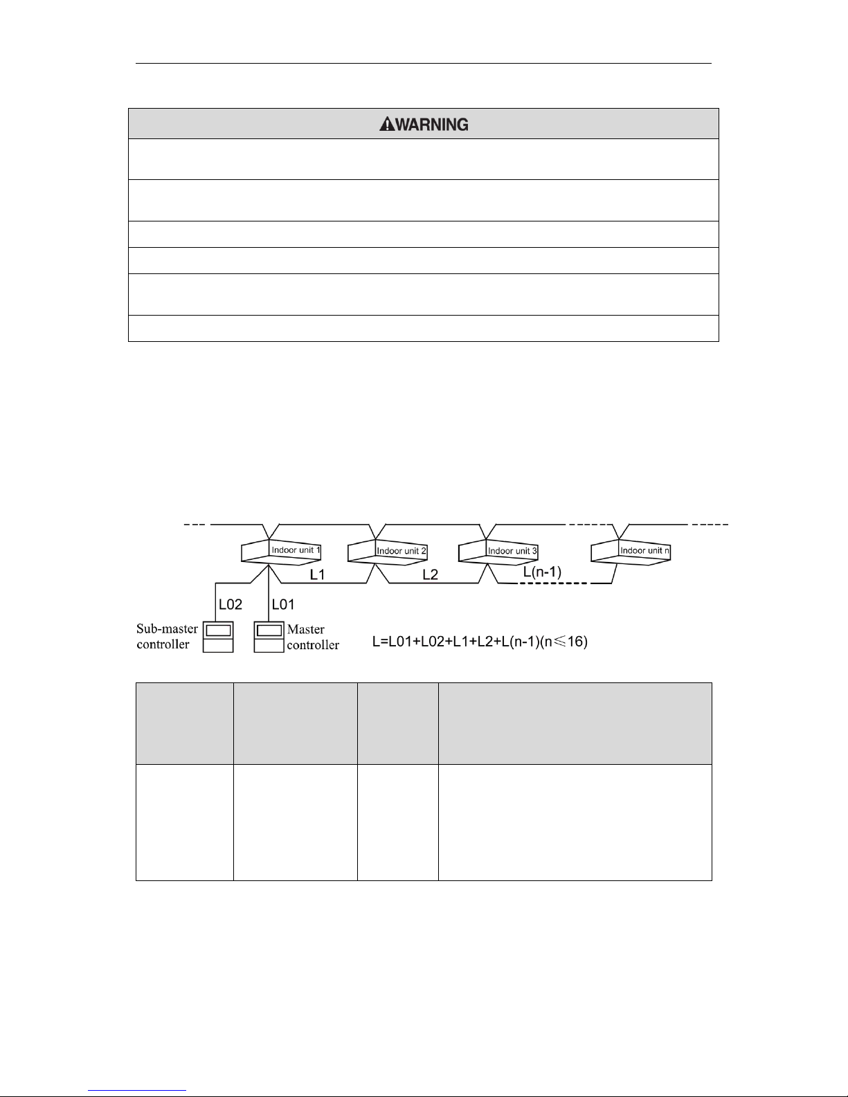
3.3.1 Select communication line for indoor unit and wired controller
Fig 3.3.1
Material type
Total length of
communication line
between IDU unit and
wired controller
L m(ft.)
Wire size
Remarks
Light/Ordinary
polyvinyl chloride
sheathed cord.
L≤250(820-1/5)
2×AWG18~
2×AWG16
①. Total length of communication line can't
exceed 250m (820-1/5feet).
②. The cord shall be Circular cord (the cores
shall be twisted together).
③. If unit is installed in places with intense
magnetic field or strong interference, it is
necessary to use shielded wire.
 Loading...