

Gree GMV-N12U/A-T(U), GMV-N24U/A-T(U), GMV-N48U/A-T(U), GMV-N192U/A-T(U), GMV-N96U/A-T(U) Owner's Manual

Owner's Manual
Original Instructions
Commercial Air Conditioners
AHU-KIT
Models:
GMV-N12U/A-T(U)
GMV-N24U/A-T(U)
GMV-N48U/A-T(U)
GMV-N96U/A-T(U)
GMV-N192U/A-T(U)
Preface
For correct installation and operation, please read all instructions carefully. Before reading the
instructions, please be aware of the following items:
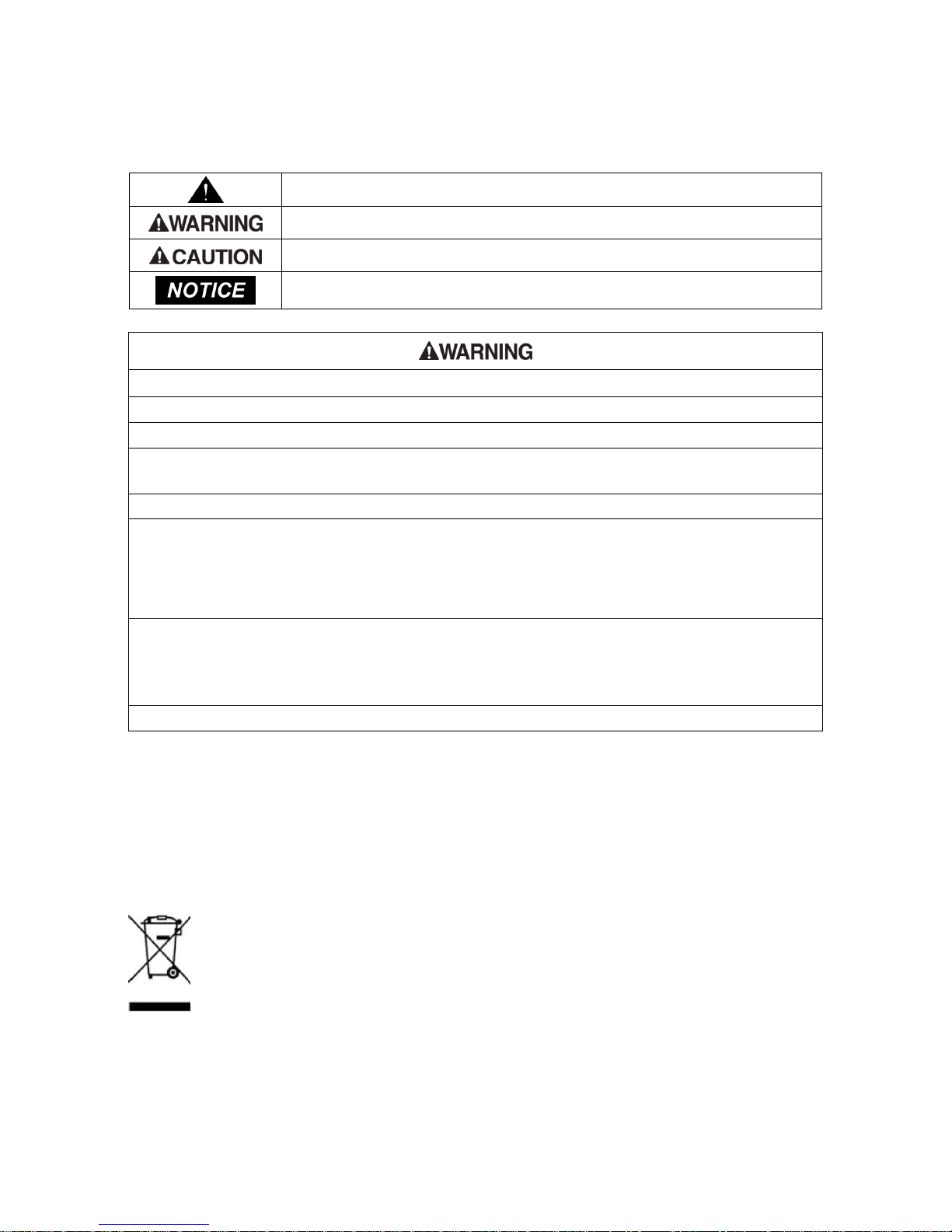
This is the safety alert symbol. It is used to alert you to potential personal injury hazards.
Obey all safety messages that follow this symbol to avoid possible injury or death.
This mark indicates procedures which, if improperly performed, might lead to the death or
serious injury of the user.
This mark indicates procedures which, if improperly performed, might possibly result in
personal harm to the user, or damage to property.
NOTICE is used to address practices not related to personal injury.
(1) Instructions for installation and use of this product are provided by the manufacturer.
(2) Installation must be performed in accordance with the requirements of NEC and CEC by authorized personnel only.
(3) For the safe operation of this unit, please read and follow the instructions carefully.
(4) During operation, total capacity of indoor units should not exceed the total capacity of outdoor units. otherwise, poor
effect of cooling or heating may result.
(5) Direct operators or maintainers should well keep this manual.
(6) If this unit fails to operate normally, please contact our service center as soon as possible and provide the following
information:
1) Content on the nameplate(model number,cooling capacity,production code,ex-factory date.
2) Malfunction details(before and after the malfunction occurs.
(7) Each unit has been strictly tested and proved to be qualified before ex-factory. In order to prevent units from being
damaged or operating normally because of improper disassembly, please do not disassemble the unit by yourself. If
you need to disassemble and check units, please contact our service center. We will send specialists to guide the
disassembly.
(8) Installation must be performed in accordance with the requirements of NEC and CEC by authorized personnel only.
T
his appliance can be used by children aged from 8 years and above and persons with
reduced physical, sensory or mental capabilities or lack of experience and knowledge if they have
been given supervision or instruction concerning use of the appliance in a safe way and
understand the hazards involved. Children shall not play with the appliance. Cleaning and user
maintenance shall not be made by children without supervision.
DISPOSAL: Do not dispose this product as unsorted municipal waste. Collection of such waste
separately for special treatment is necessary.

Contents
1 Safety Precautions .................................................................................................. 1
2 Product Introduction ................................................................................................ 3
2.1 Names of Key Components ................................................................................................ 3
2.2 Overall System Connection Diagram .................................................................................. 3
2.3 Standard Fittings ................................................................................................................. 5
2.4 Specifications ...................................................................................................................... 5
2.5 Selecting the Air Handling Unit ........................................................................................... 7
3 Preparations for Installation .................................................................................... 11
3.1 Before Installation .............................................................................................................. 11
3.2 Location for Installation ..................................................................................................... 12
3.3 Requirements for Communication Wire ............................................................................ 13
3.4 Wiring Requirements......................................................................................................... 15
3.5 Piping Requirements ......................................................................................................... 16
3.6 Capacity Setting ................................................................................................................ 19
4 Installation Instructions ...........................................................................................20
4.1 Unit Dimensions and Maintenance Space ........................................................................ 20
4.2 EXV Installation ................................................................................................................. 23
4.3 Installation of the EXV Cable ............................................................................................ 25
4.4 Piping Installation .............................................................................................................. 25
4.5 Installation of the Control Box ........................................................................................... 27
4.6 Installation of the Temperature sensors ............................................................................ 29
4.7 Installation of Wired Controller .......................................................................................... 32
5 Wire Connection .....................................................................................................33
5.1 Connect Cables and Terminals of Wiring Board ............................................................... 33
5.2 Power Cord Connection .................................................................................................... 34
5.3 Connection of Communication Wire between Indoor Unit and Outdoor Unit (or Indoor Unit)
................................................................................................................................................. 35
5.4 Connect Communication Wire of Wired Controller ........................................................... 36
5.5 Illuminate for Connection of Wired Controller and Indoor Units (AHU-KIT) Network ....... 36
6 Statement on linkage function setting .....................................................................38
7 Operation and Maintenance ...................................................................................38
7.1 Before Operation ............................................................................................................... 38
7.2 Test Operation ................................................................................................................... 39
7.3 Routine Maintenance ........................................................................................................ 39
7.4 Disposal Requirements ..................................................................................................... 40
8 Table of Error Codes for Indoor Unit .......................................................................40

AHU-KIT
1
1 Safety Precautions
(1) Follow this instruction to complete the installation work. Please carefully read this manual before unit startup
and service.
(2) Wire size of power cord should be large enough. The damaged power cord and connection wire should be
replaced by exclusive cable.
(3) After connecting the power cord, please fix the electric box cover properly in order to avoid accident.
(4) Never fail to comply with the nitrigen charge requirements. Charge nitrogen when welding pipes.
(5) Never short-circiut or cancel the pressure switch to prevent unit damage.
(6) Please firstly connect the wired controller before energization , otherwise wired controller can not be used.
(7) Before using the unit, please check if the piping and wiring are correct to avoid water leakage, refrigerant
leakage, electric shock, or fire etc..
(8) Do not insert fingers or objects into air outlet/inlet grille.
(9) Open the door and window and keep good ventilation in the room to avoid oxygen deficit when the gas/oil
supplied heating equipment is used.
(10) Never start up or shut off the air conditioner by means of directly plug or unplug the power cord.
(11) Turn off the unit after it runs at least five minutes; otherwise it will influence oil return of the compressor.
(12) Do not allow children operate this unit.
(13) Do not operate this unit with wet hands.
(14) Turn off the unit or cut off the power supply before cleaning the unit, otherwise electric shock or injury may
happen.
(15) Never spray or flush water towards unit, otherwise malfunction or electric shock may happen.
(16) Do not expose the unit to the moist or corrosive circumstances.
(17) Under cooling mode, please don't set the room temperature too low and keep the temperature difference
between indoor and outdoor unit within 5℃(41℉).
(18) User is not allowed to repair the unit. Fault service may cause electric shock or fire accidents. Please
contact Gree appointed service center for help.
(19) Before installation, please check if the power supply is in accordance with the requirements specified on the
nameplate. And also take care of the power safety.
(20) Installation should be conducted by dealer or qualified personnel. Please do not attempt to install the unit by
yourself. Improper handling may result in water leakage, electric shock or fire disaster etc..
(21) The control box should be installed inside
(22) Be sure to use the exclusive accessory and part to prevent the water leakage, electric shock and fire
accidents.
(23) Make sure the unit can be earthed properly and soundly after plugging into the socket so as to avoid electric
shock. Please do not connect the ground wire to gas pipe, water pipe, lightning rod or telephone line.

AHU-KIT
2
(24) Electrify the unit 8 hours before operation. Please switch on for 8 hours before operation. Do not cut off the
power when 24 hours short-time halting (to protect the compressor).
(25) If refrigerant leakage happens during installation, please ventilate immediately. Poisonous gas will emerge
if the refrigerant gas meets fire.
(26) Volatile liquid, such as diluent or gas will damage the unit appearance. Only use soft cloth with a little
neutral detergent to clean the outer casing of unit.
(27) If anything abnormal happens (such as burning smell), please power off the unit and cut off the main power
supply, and then immediately contact Gree appointed service center .If abnormality keeps going, the unit might
be damaged and lead to electric shock or fire.
Any personal injury or property loss caused by improper installation, improper debug,
unnecessary repair or not following the instructions of this manual should not be the responsibility
of Gree Electric Appliances, Inc. of Zhuhai.
AHU-KIT
3
2 Product Introduction
2.1 Names of Key Components
Fig.2.1
No.
①
②
Name
Control Box
EXV Box
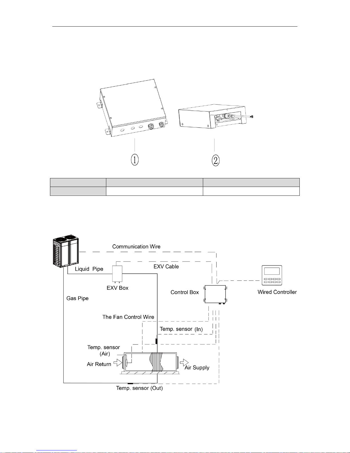
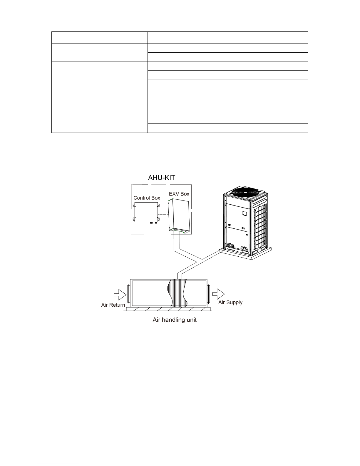
2.2 Overall System Connection Diagram
When one AHU-KIT is connected to one AHU, the connection diagram is as follows:
Fig.2.2.1
AHU-KIT
4
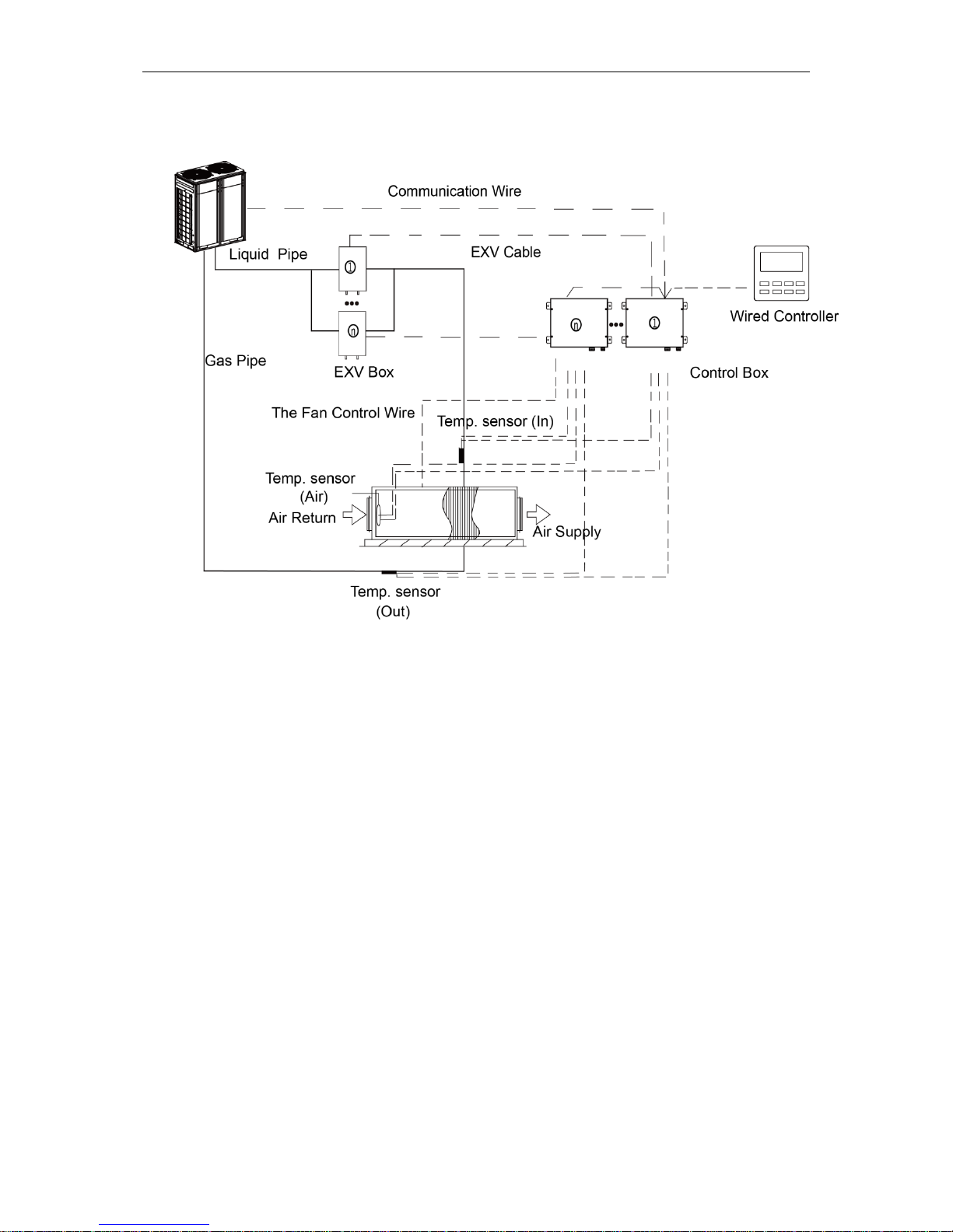
When several AHU-KITs (n≤2) are in parallel connection with one AHU, the connection
diagram is as follows:
Fig.2.2.2
AHU-KIT
5
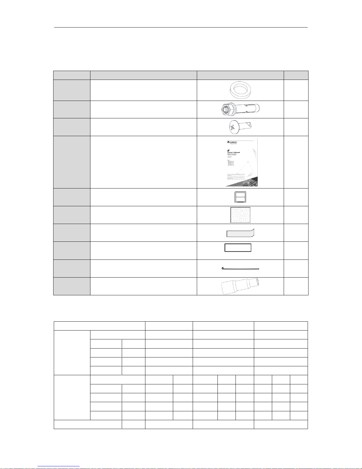
2.3 Standard Fittings
Please use the supplied standard fittings listed below as instructed.
No.
Name
Appearance
Quantity
1
Magnetic ring
1 or 2
2
Swell screw
4
3
Self-tapping screw
4
4
Operating Instruction Manual
1
5
Wired controller
1
6
Insulator
2
7
aluminum tape
2
8
rubber belt
2
9
Fastener
4
10
Reducer pipe(Only for 24, 96, 192 type)
2
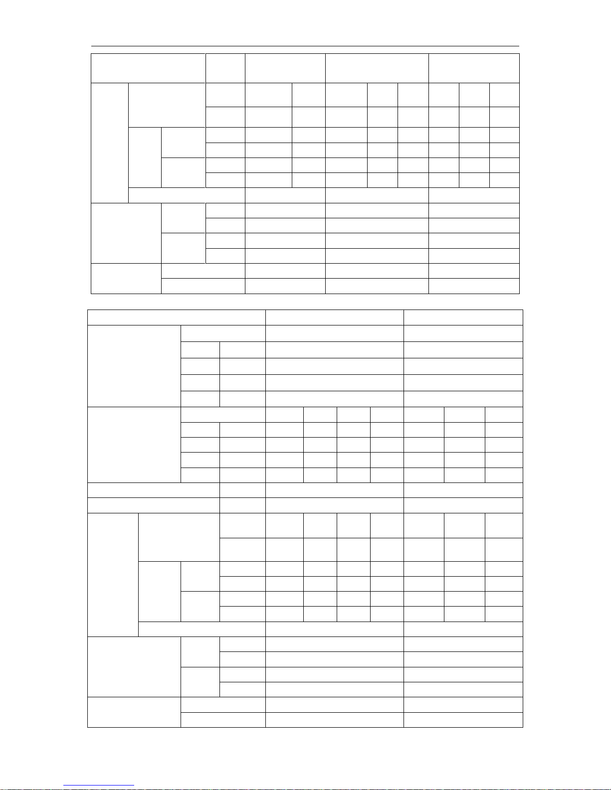
2.4 Specifications
Model
GMV-N12U/A-T(U)
GMV-N24U/A-T(U)
GMV-N48U/A-T(U)
Defaulted
capacity of
ex-factory
Capacity
12
24
48
Cooling
kW
3.52
7.03
14.07
Cooling
kBtu/h
12.0
24.0
48.0
Heating
kW
3.96
7.91
15.83
Heating
kBtu/h
13.5
27.0
54.0
Adjustable
capacity
Capacity
9
12
15
18
24
30
36
48
Cooling
kW
2.64
3.52
4.40
5.28
7.03
8.79
10.55
14.07
Cooling
kBtu/h
9.5
12.0
15.0
18.0
24.0
30.0
36.0
48.0
Heating
kW
3.08
3.96
4.98
5.86
7.91
9.96
11.72
15.83
Heating
kBtu/h
10.5
13.5
17.0
20.0
27.0
34.0
40.0
54.0
Power input
W
5.0
5.0
5.0
AHU-KIT
6
Power Supply
Ph /V /Hz
1-Ph 208/230V
60Hz
1-Ph 208/230V 60Hz
1-Ph 208/230V 60Hz
Size of
connecti
on pipe
AHU-KIT
(ex-factory pipe
size)
mm
Φ6.35
Φ6.35
Φ9.52
Φ9.52
Φ9.52
Φ9.52
Φ9.52
Φ9.52
in.
1/4
1/4
3/8
3/8
3/8
3/8
3/8
3/8
Air
handlin
g unit
Liquid pipe
mm
Φ6.35
Φ6.35
Φ6.35
Φ9.52
Φ9.52
Φ9.52
Φ9.52
Φ9.52
in.
1/4
1/4
1/4
3/8
3/8
3/8
3/8
3/8
Gas pipe
mm
Φ9.52
Φ12.7
Φ12.7
Φ15.9
Φ15.9
Φ15.9
Φ15.9
Φ15.9
in.
3/8
1/2
1/2
5/8
5/8
5/8
5/8
5/8
Connection method
Brazing Connection
Brazing Connection
Brazing Connection
Outline dimension
(W×D×H)
EXV box
mm
203×326×85
203×326×85
203×326×85
in.
8×12-7/8×3-3/8
8×12-7/8×3-3/8
8×12-7/8×3-3/8
Control
box
mm
334×284×111
334×284×111
334×284×111
in.
13-1/8×11-1/8×4-3/8
13-1/8×11-1/8×4-3/8
13-1/8×11-1/8×4-3/8
Net weight
kg
9.5
9.5
9.5
lbs
21
21
21
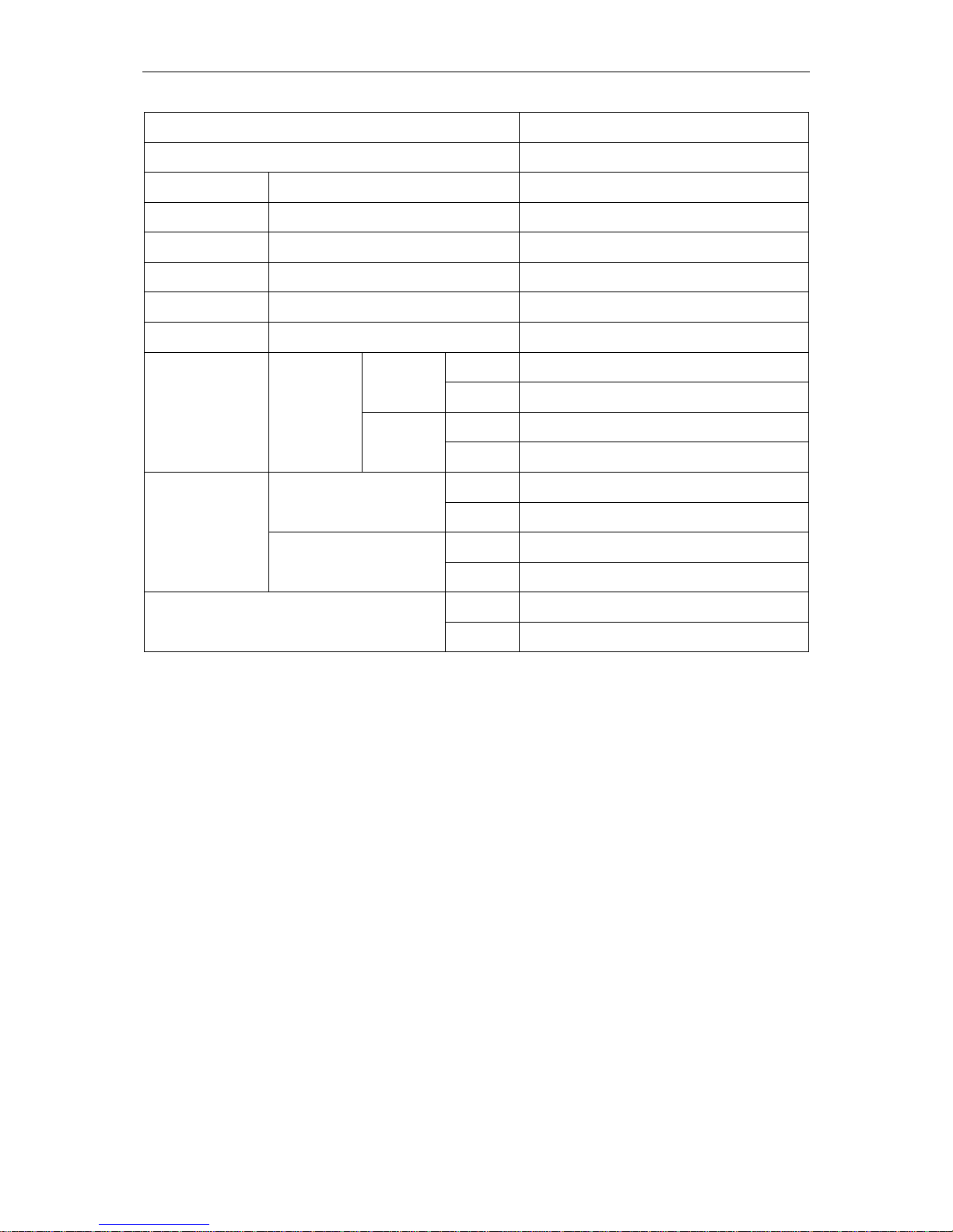
Model
GMV-N96U/A-T(U)
GMV-N192U/A-T(U)
Defaulted capacity of
ex-factory
Capacity
96
192
Cooling
kW
28.14
56.27
Cooling
kBtu/h
96.0
192
Heating
kW
31.65
63.31
Heating
kBtu/h
108.0
216
Adjustable capacity
Capacity
72
96
120
144
168
192
288
Cooling
kW
21.10
28.14
35.17
42.20
49.24
56.27
84.41
Cooling
kBtu/h
72
96
120
144
168
192
288
Heating
kW
23.74
31.65
39.57
47.48
55.39
63.31
94.96
Heating
kBtu/h
81
108
135
162
189
216
324
Power input
W
5.0
5.0
Power Supply
Ph /V/ Hz
1-Ph 208/230V 60Hz
1-Ph 208/230V 60Hz
Size of
connection
pipe
AHU-KIT
(ex-factory pipe
size)
mm
Φ9.52
Φ9.52
Φ9.52
Φ9.52
Φ15.9
Φ15.9
Φ15.9
in.
3/8
3/8
3/8
3/8
5/8
5/8
5/8
Air
handling
unit
Liquid
pipe
mm
Φ9.52
Φ9.52
Φ12.7
Φ12.7
Φ15.9
Φ15.9
Φ19.05
in.
3/8
3/8
1/2
1/2
5/8
5/8
3/4
Gas
pipe
mm
Φ19.05
Φ22.2
Φ28.6
Φ28.6
Φ28.6
Φ28.6
Φ34.9
in.
3/4
7/8
1-1/8
1-1/8
1-1/8
1-1/8
1-3/8
Connection method
Brazing Connection
Brazing Connection
Outline dimension
(W×D×H)
EXV
box
mm
203×326×85
246×500×120
in.
8×12-7/8×3-3/8
9-5/8×19-5/8×4-3/4
Control
box
mm
334×284×111
334×284×111
in.
13-1/8×11-1/8×4-3/8
13-1/8×11-1/8×4-3/8
Net weight
kg
9.5
13
lbs
21
28
AHU-KIT
7
Model(Combined)
GMV-N48U/A-T(U)+GMV-N192U/A-T(U)
Capacity
48+288
Cooling
kW
98.48
Cooling
kBtu/h
336
Heating
kW
110.79
Heating
kBtu/h
378
Power input W 5.0+5.0
Power supply
Ph /V/Hz
1-Ph 208/230V 60Hz
Size of connection
pipe
Air handling
unit
Liquid pipe
mm
Φ19.05
in.
3/4
Gas pipe
mm
Φ34.9
in.
1-3/8
Outline dimension
(W×D×H)
Electronic expansion valve
box
mm
(203×326×85)+(246×500×120)
in.
(8×12-7/8×3-3/8)+(9-5/8×19-5/8×4-3/4)
Control box
mm
(334×284×111)×2
in.
(13-1/8×11-1/8×4-3/8)×2
Net weight
kg
9.5+13
lbs
21+28
NOTICE!
The specifications of the unit is subject to change without prior notice due to improvement
product. Please refer to the nameplate.
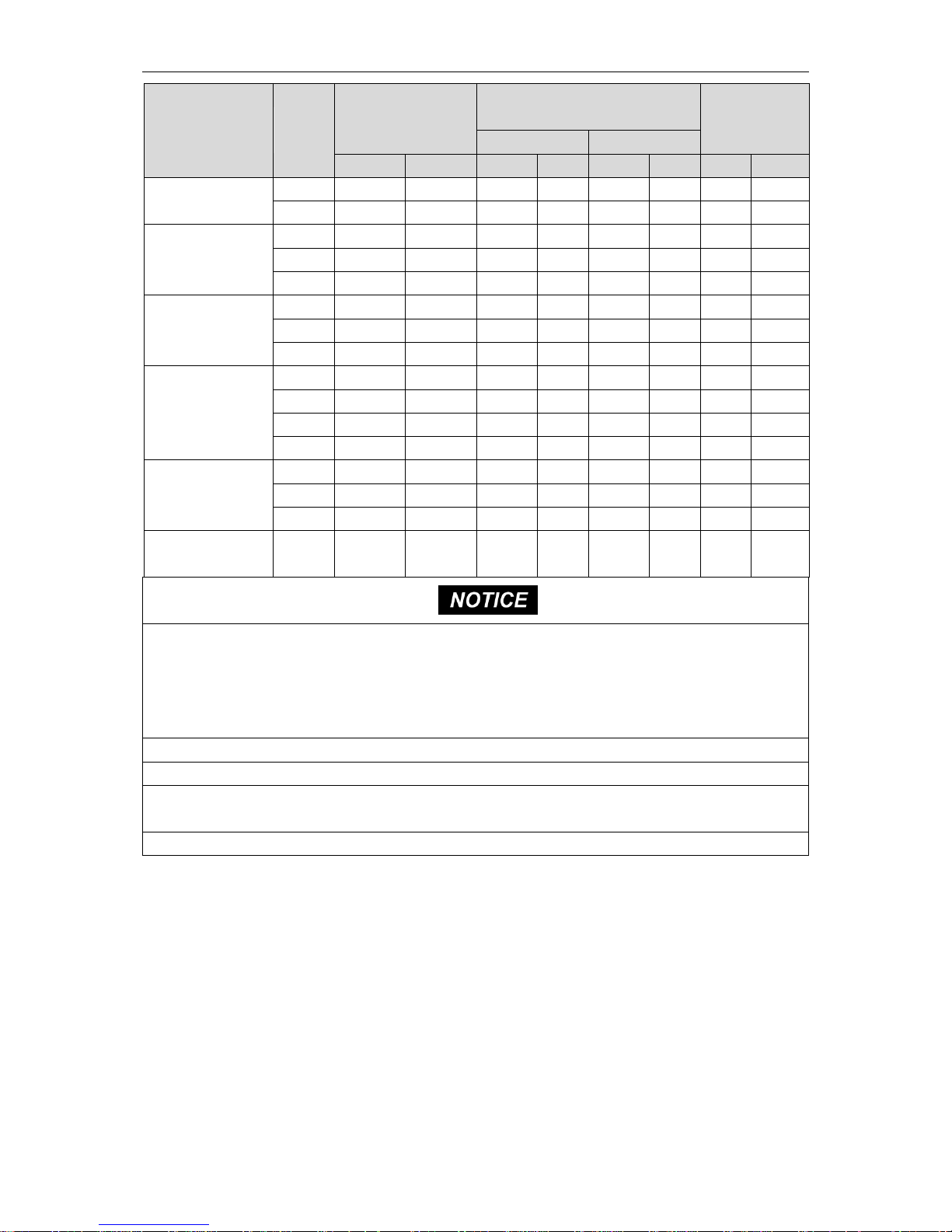
2.5 Selecting the Air Handling Unit
Select the air handling unit according to the technical data and limitations mentioned in the
following table. Lifetime of the unit, operation range or operation reliability may be influenced if you
neglect these limitations.
AHU-KIT
8
Model(Combined)
Capacity
(kBtu/h)
Allowed Heat
Exchanger
Volume(dm3)
Allowed Heat Exchanger
Capacity(kBtu/h)
Suggested Air
Flow(CFM)
Cooling
Heating
Min
Max
Min
Max
Min
Max
Min
Max
GMV-N12U/A-T(U)
9
0.67
0.74
8.5
9.5
9.5
10.5
220
295
12
0.78
0.94
9.5
12
10.5
13.5
245
375
GMV-N24U/A-T(U)
15
0.94
1.17
12
15
13.5
17
310
465
18
1.17
1.41
15
18
17
20
390
560
24
1.41
1.88
18
24
20
27
465
745
GMV-N48U/A-T(U)
30
1.88
2.35
24
30
27
34
620
930
36
2.35
2.82
30
36
34
40
775
1120
48
2.82
3.76
36
48
40
54
930
1490
GMV-N96U/A-T(U)
72
3.76
5.63
48
72
54
81
1240
2235
96
5.63
7.51
72
96
81
108
1865
2980
120
7.51
9.39
96
120
108
135
2485
3725
144
9.39
11.27
120
144
135
162
3105
4470
GMV-N192U/A-T(U)
168
11.27
13.15
144
168
162
189
3725
5215
192
13.15
15.02
168
192
189
216
4345
5960
288
15.02
22.54
192
288
216
324
4970
8945
GMV-N48U/A-T(U)+
GMV-N192U/A-T(U)
336
22.54
26.29
288
336
324
378
7450
10435
a) The capacity is obtained at these test conditions: superheat (SH) = 5℃(41℉) and supercool (SC) = 3℃(37.4
℉).
Cooling: Saturated evaporating temperature = 6℃(42.8℉), air return temperature is 27℃(80.6℉)DB/19℃
(66.2℉)WB.
Heating: Saturated condensing temperature = 46℃(114.8℉), air return temperature is 20℃(68℉)DB.
b) The heat exchanger of air handling unit is designed for R410A, and it’s working pressure is 3.8MPa.
c) Quantity of rows of heat exchanger: no more than 4 rows.
d) The diameter of copper pipe of heat exchanger is no more than 12.7mm(1/2 in.), 9.52mm(3/8 in.) is
recommended.
e) Air inlet temperature range of heat exchanger: cooling: 16~35℃(60.8~95℉), heating: 10~27℃(50~80.6℉).
NOTICE!
When the AHU-KIT is matched with AHU, they can connect with VRF outdoor unit as VRF
indoor unit. The connection is limited by the outdoor unit. There are three kinds of connection
method:
(1) Connection method 1: one-to-one
The AHU-KIT as below can adopt one-to-one connection method with VRF outdoor unit. Total
capacity of AHU-KIT should be 80%~110% of that of outdoor unit.
AHU-KIT
9
Model(Combined)
Capacity in application (kBtu/h)
Capacity DIP
GMV-N24U/A-T(U)
24
24
GMV-N48U/A-T(U)
30
30
36
36
48
48
GMV-N96U/A-T(U)
72
72
96
96
120
120
144
144
GMV-N192U/A-T(U)
168
168
192
192
288
288
GMV-N48U/A-T(U)+GMV-N192U/A-T(U)
336
48+288
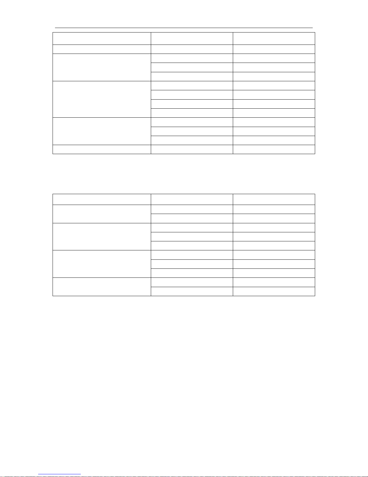
(2) Connection method 2: one-to-more
The AHU-KIT as below can adopt one-to-more connection method with VRF outdoor unit.
Total capacity of AHU-KIT should be 50%~110% of that of outdoor unit.
Model
Capacity in application (kBtu/h)
Capacity DIP
GMV-N12U/A-T(U)
9
28
12
36
GMV-N24U/A-T(U)
15
45
18
56
24
71
GMV-N48U/A-T(U)
30
90
36
112
48
140
GMV-N96U/A-T(U)
72
224
96
280
(3) Connection method 3: one-to-more (mixed connection)
The AHU-KIT as below can adopt one-to-more connection method with general VRF indoor
unit. Total capacity of AHU-KIT and VRF indoor unit should be 50%~110% of that of outdoor unit.
Total capacity of AHU-KIT cannot exceed 30% of that of outdoor unit.
AHU-KIT
10
Model
Capacity in application (kBtu/h)
Capacity DIP
GMV-N12U/A-T(U)
9
28
12
36
GMV-N24U/A-T(U)
15
45
18
56
24
71
GMV-N48U/A-T(U)
30
90
36
112
48
140
GMV-N96U/A-T(U)
72
224
96
280
NOTICE!
When connecting AHU-KIT with general VRF indoor unit, capacity requirement shall be
followed strictly. Otherwise, it may affect the operation, or even damage the unit.
Fig.2.5.1 AHU-KIT one-to-one (single unit) connection diagram

AHU-KIT
11
Fig.2.5.2 AHU-KIT one-to-one (combination outdoor unit) connection diagram
Fig.2.5.3 AHU-KIT one-to-more (hybrid connection) connection diagram
3 Preparations for Installation
3.1 Before Installation
NOTICE!
Product graphics are only for reference. Please refer to actual products. Unspecified measure
unit is mm(in.).
(1) This equipment is designed for R410A system, and the designed working pressure is
3.8 MPa or 38 bar.
 Loading...