

Gree GMV-N140U/A-T, GMV-N560U/A-T, GMV-N280U/A-T Owner's Manual

Owner's Manual
Air Conditioners
Models:
GMV-N140U/A-T
GMV-N280U/A-T
GMV-N560U/A-T
Gree Electric Appliances, Inc. of Zhuhai
Thank you for choosing Air Conditioners, please read this owner’s manual carefully before
operation and retain it for future reference.
GREE reserves the right to interpret this manual which will be subject to any change due to
product improvement without further notice.
GREE Electric Appliances, Inc. of Zhuhai reserves the final right to interpret this manual. If
you have lost the Owner’s Manual, please contact the local agent or visit www.gree.com or
sent email to global@gree.com.cn or electronic version.
INSTALLATION AND OPERATION MANUAL
FOR AHU-KIT UNIT
Preface
For correct installation and operation, please read all instructions carefully. Before reading the
instructions, please be aware of the following items:
(1) For the safe operation of this unit, please read and follow the instructions carefully.
(2) During operation, total capacity of indoor units should not exceed the total capacity of
outdoor units. Otherwise, poor effect of cooling or heating may result.
(3) Direct operators or maintainers should well keep this manual.
(4) If this unit fails to operate normally, please contact our service center as soon as possible
and provide the following information:
Content on the nameplate (model number, cooling capacity, production code, ex-factory
date).
Malfunction details (before and after the malfunction occurs).
(5) Each unit has been strictly tested and proved to be qualified before ex-factory. In order to
prevent units from being damaged or operating normally because of improper
disassembly, please do not disassemble the unit by yourself. If you need to disassemble
and check units, please contact our service center. We will send specialists to guide the
disassembly.
(6) Do only use this system in combination with a field supplied air handling unit. Do not
connect this system to other appliances.
(7) The outdoor unit and the air handling unit can both influence the overall performance of
the unit, please be sure to select appropriate outdoor unit, air handling unit and AHU-KIT
unit according to actually apply requirements.
(8) This equipment is not designed for year-round cooling applications with low indoor
humidity conditions, such as Electronic Data Processing rooms.
(9) All graphics in this manual is only for your reference. For sales or production reasons,
these graphics are subject to change by manufacturer without prior notice.
User Notice
This appliance can be used by children aged from 8 years and above and persons with
reduced physical, sensory or mental capabilities or lack of experience and knowledge if
they have been given supervision or instruction concerning use of the appliance in a safe
way and understand the hazards involved. Children shall not play with the appliance.
Cleaning and user maintenance shall not be made by children without supervision.
Disposal
This marking indicates that this product should not be disposed
with other household wastes throughout the EU. To prevent
possible harm to the environment or human health from
uncontrolled waste disposal, recycle it responsibly to promote the
sustainable reuse of material resources. To return your used
device, please use the return and collection systems or contact
the retailer where the product was purchased. They can take this
product for environmental safe recycling.

Contents
1 Safety Precautions ............................................................................................... 1
2 Product Introduction ............................................................................................. 3
2.1 Names of Key Components.................................................................................................. 3
2.2 Overall System Connection Diagram .................................................................................. 3
3 Preparations for Installation ................................................................................. 4
3.1 Before Installation .................................................................................................................. 4
3.2 Standard Fittings .................................................................................................................... 4
3.3 Selecting the Air Handling Unit ............................................................................................ 5
3.4 Selecting the AHU-KIT Unit .................................................................................................. 5
3.5 Location for Installation ......................................................................................................... 6
3.6 Requirements for Communication Wire .............................................................................. 7
3.7 Wiring Requirements ............................................................................................................. 8
4 Installation Instructions ......................................................................................... 9
4.1 Unit Dimensions and Maintenance Space ......................................................................... 9
4.2 Piping Installation ................................................................................................................. 11
4.3 EXV Installation .................................................................................................................... 13
4.4 Installation of the Control Box ............................................................................................ 14
4.5 Installation of the Thermistors ............................................................................................ 16
4.6 Installation of the EXV Cable .............................................................................................. 18
4.7 Installation of Wired Controller ........................................................................................... 18
5 Wire Connection .................................................................................................18
5.1 Connect Cables and Terminals of Wiring Board .............................................................. 19
5.2 Power Cord Connection ...................................................................................................... 20
5.3 Connection of Communication Wire between Indoor Unit and Outdoor Unit (or Indoor
Unit) ...................................................................................................................................................... 20
5.4 Connect Communication Wire of Wired Controller ......................................................... 21
5.5 Illuminate for Connection of Wired Controller and Indoor Units (AHU-KIT) Network 21
6 Operation and Maintenance ................................................................................22
6.1 Before Operation .................................................................................................................. 22
6.2 Test Operation ...................................................................................................................... 23
6.3 Routine Maintenance........................................................................................................... 23
6.4 Disposal Requirements ....................................................................................................... 24
7 Table of Error Codes for Indoor Unit ....................................................................24
8 Troubleshooting ..................................................................................................25
OPERATING INSTALLATION MANUAL FOR AHU-KIT UNIT
1
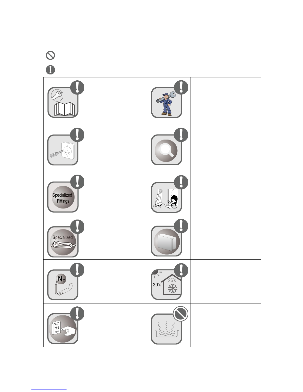
1 Safety Precautions
means items that must be forbidden! Otherwise, it may lead to personal injury or death or
serious damage.
means items that must be followed! Otherwise, it may lead to personal injury or property
loss.
Please install the unit
according to instructions in
this manual. Read this
manual carefully before
starting up or checking the
machine.
Installation should be performed by
dealer or qualified technicians. Do
not install the product by yourself.
Improper installation may result in
water leakage, electric shock or fire
hazard.
Make sure the local power
supply is in accordance with
units before installation, and
check the power supply
carefully.
When the installation is finished,
please check and make sure the
drain pipe, pipeline and electric
wire are all well connected in order
to avoid water leakage, refrigerant
leakage, electric shock or fire
hazard.
Please use specialized
accessories or parts to carry
out installation, or water
leakage, electric shock, fire
hazard may resulted.
R410A refrigerant can produce
poisonous gas once it meets fire,
so please ventilate the room
immediately if refrigerant leaks out
during installation.
Diameter of power cord must
be large enough. Damaged
power cord and connecting
wire must be replaced by
specialized electric cable.
After the power cord is connected,
please install the cover of electric
box to avoid danger.
Nitrogen must be charged
according to technical
requirements.
During Cooling mode, indoor
temperature should not be set too
low. Keep the difference between
indoor temp and outdoor temp
within 5°C.
For units with wired controller,
do not connect power supply
until the wired controller is
well installed. Otherwise, the
wired controller cannot be
used.
Volatile liquid like thinner or
gasoline will damage the
appearance of this product. (Please
use soft dry cloth and wet cloth with
mild detergent to clean the outer
case of air conditioner.)
OPERATING INSTALLATION MANUAL FOR AHU-KIT UNIT
2
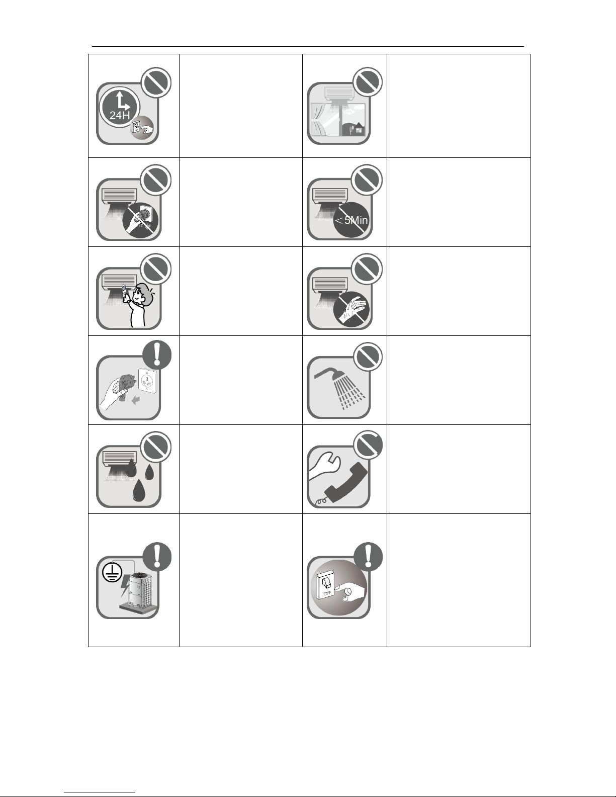
Connect power supply 8
hours before operation. Do
not disconnect power if you
want to stop the unit in a short
period of time, e.g. in one
night. (This is for protecting
the compressor.)
If you use gas heater or
petroleum heater in the same room,
please open the door or window to
maintain good air circulation in
case the room may lack of oxygen.
Never start or stop this
product by inserting or
removing the power cord.
Do not turn off the air conditioner
until it runs for at least 5 minutes.
Otherwise, oil-return of the
compressor will be affected.
Children are not allowed to
operate this product.
Do not operate this product with
wet hands.
Please turn the unit off and
unplug your air conditioner
before cleaning. Otherwise, it
may cause electric shock or
personal injury.
Do not spray water on this product
or it will cause malfunction or
electric shock.
Do not expose this product
directly to water or place it in
a damp or corrosive
environment.
Do not repair this product by
yourself. Improper repair will cause
electric shock or fire hazard. Please
contact GREE service center and
have it repaired by professional
technicians.
This product must be properly
grounded through the
receptacle to avoid electric
shock. The grounding wire
shouldn't be connected with
gas pipe, water pipe, lightning
arrester or telephone line.
If abnormal condition occurs (e.g.
unpleasant smell), please turn off
the unit at once and disconnect
power supply. Then contact GREE
service center. If the air conditioner
continues to operate despite of
abnormal condition, the unit may be
damaged and it may cause electric
shock or fire hazard.)
Any personal injury or property loss caused by improper installation, improper debug,
unnecessary repair or not following the instructions of this manual should not be the responsibility
of Gree Electric Appliances, Inc. of Zhuhai.
OPERATING INSTALLATION MANUAL FOR AHU-KIT UNIT
3
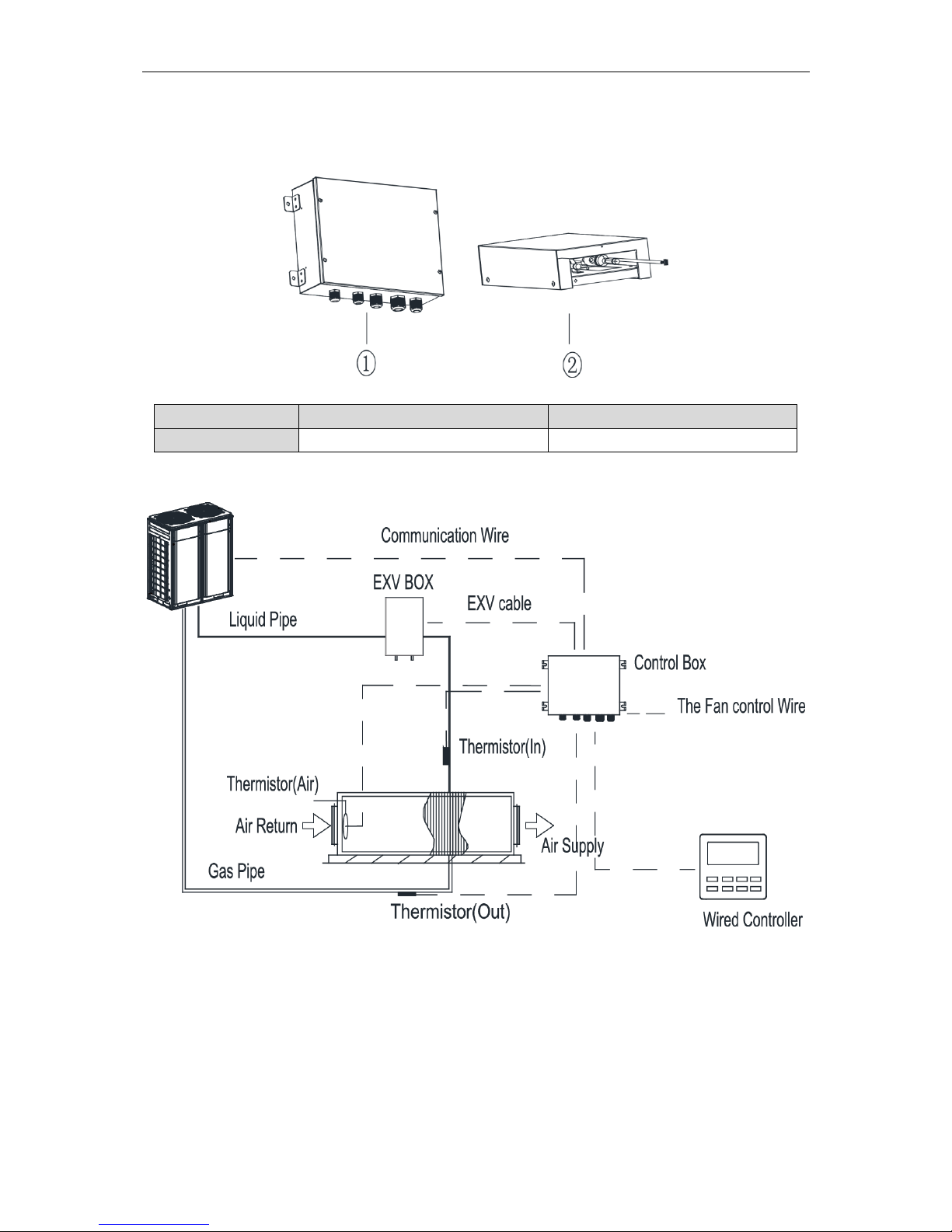
2 Product Introduction
2.1 Names of Key Components
Fig.2.1
No.
①
②
Name
Control Box
Expansion valve kit Box
2.2 Overall System Connection Diagram
Fig.2.2
OPERATING INSTALLATION MANUAL FOR AHU-KIT UNIT
4
3 Preparations for Installation
3.1 Before Installation
Notes: Product graphics are only for reference. Please refer to actual products.
Unspecified measure unit is mm.
① This equipment is designed for R410A system, and the designed working pressure is 4.2
MPa or 42 bar.
② Precautions for R410A:
a).The refrigerant requires strict cautions for keeping the system clean, dry and tight.
—Clean and dry:Foreign materials (including mineral oils or moisture)should be prevented
from getting mixed into the system.
—Tight:Read this manual carefully and follow these procedures correctly.
b).Since R410A is a mixed refrigerant, the required additional refrigerant must be charged
in its liquid state. ( If the refrigerant is in state of gas, its composition changes and the
system will not work properly).
c).The connected air handling units must have heat exchangers designed exclusively for
R410A.
③ Never use this appliance under inflammable and explosive gas.
④ For the following items, take special care during construction and check after installation
is finished:
Tick √ when checked
□ Are the thermistors fixed firmly?
Thermistor may come loose.
□ Is the capacity code setted correctly?
The performance of system may not achieve it’s requirement.
□ Is the control box fixed firmly?
The unit may drop, vibrate or make noise.
□ Do electrical connections comply with specifications?
The unit may malfunction or components may burn out.
□ Are wiring and piping correct?
The unit may malfunction or components may burn out.
□ Is the unit safely grounded?
Dangerous at electric leakage.
3.2 Standard Fittings
Please use the supplied standard fittings listed below as instructed.
No.
Name
Appearance
Quantity
1
Magnetic ring
1
2
Swell screw
4
OPERATING INSTALLATION MANUAL FOR AHU-KIT UNIT
5
3
Self-tapping screw
4
4
Operating Instruction Manual
1
5
Wired controller
1
3.3 Selecting the Air Handling Unit
Select the air handling unit according to the technical data and limitations mentioned in the
following table. Lifetime of the outdoor unit, operation range or operation reliability may be
influenced if you neglect these limitations.
Model
capacity
(kW)
Allowable internal volume
of heat exchanger (dm3)
Allowable capacity of
heat exchanger (kW)
Suggested air
volume (m3/h)
Minimum
Maximum
Minimum
Maximum
GMV-N140U/A-T
9.0
2.09
2.64
7.9
9.9
1500~1850
11.2
2.65
3.3
10
12.3
1850~2100
14.0
3.31
4.12
12.4
15.4
2100~2400
GMV-N280U/A-T
22.4
4.63
6.60
17.7
24.6
3700~4200
28.0
6.61
8.25
24.7
30.8
4200~4800
GMV-N560U/A-T
45.0
10
11.8
42.5
47.5
7400~8000
50.4
11.9
13.7
47.6
53.2
8000~5600
56.0
13.8
15.6
53.3
58.7
8600~9200
Notes:
a) The capacity of heat exchanger is obtained at these test conditions: evaporation temperature at air outlet of
heat exchanger is 6℃, overheating degree of heat exchanger is 5℃ and the air return temperature is 27℃
DB/19℃WB.
b) The heat exchanger of air handling unit is designed for R410A, and it’s working pressure is 4.2MPa.
c) Quantity of rows of heat exchanger: no more than 4 rows.
d) The diameter of copper pipe of heat exchanger is no more than 12.7mm. 9.52mm is recommended.
Notes: The air handling unit can be connected as a standard indoor unit to the outdoor unit.
The limitations of connection are determined by the outdoor unit.
3.4 Selecting the AHU-KIT Unit
The corresponding AHU-KIT unit needs to be selected for your air handling unit. Select the
AHU-KIT unit according to the above limitations.
Capacity ranges of different AHU-KIT unit are as follows:
Model
Acquiescent capacity (kW)
Adjustable capacity (kW)
GMV-N140U/A-T
14.0
9.0/11.2/14.0
GMV-N280U/A-T
28.0
22.4/28
GMV-N560U/A-T
56.0
45/50.4/56
Different capacities of same model of AHU-KIT unit are achieved through dialing capacity
code of mainboard (shown as "S1").Capacity code setting is shown as follows:
OPERATING INSTALLATION MANUAL FOR AHU-KIT UNIT
6
S1
Capacity
(kW)
1 2 3 4 5 0 0 1 1 0 9.0
0 1 1 1 0
11.2
0 0 0 0 1
14.0
1 1 0 0 1
22.4
1 0 1 0 1
28.0
1 0 0 1 1
45.0
0 1 0 1 1
50.4
1 1 0 1 1
56
Please ensure dialing the code switch properly in place instead of middle position. Setting the
switch to "ON" stands for "0", otherwise stands for "1".
(Notes: The black part is the deflector rod.) The figure shows that the addresses of ”1,2,3,4,5”
are ”0,0,1,0,0”.
Notes:
① The selected air handling unit must be designed for R410A.
② Extraneous substances (including mineral oils or moisture) must be prevented from
getting mixed into the system.
3.5 Location for Installation
Select an installation site where the following conditions are fulfilled and that meets your
customer’s approval.
(1) The EXV box can be installed inside and outside. The control box should be installed
inside.
(2) Do not install the EXV box in or on the outdoor unit.
(3) Do not put the option boxes in direct sunlight. Direct sunlight will increase the
temperature inside the option boxes and may reduce its lifetime and influence its
operation.
(4) Choose a flat and strong mounting surface.
(5) Make sure there is enough free space in front and in the side of the AHU-KIT unit for
future maintenance.
(6) The installation site should be far away from heat source, inflammable gas and smoke.
(7) Keep the air handling unit, power supply wiring and transmission wiring at least 1 m away
from televisions and radios. This is to prevent image interference and noise in those
electrical appliances. (Noise may be generated depending on the conditions under which
the electric wave is generated, even if 1 m is kept.)
(8) Make sure the electronic expansion valve is installed in an upright position.
 Loading...