

Gree GMV-36WL/B-T(U), GMV-48WL/B-T(U), GMV-HY36WLT/A-T(U), GMV-HY48WLT/A-T(U) User Manual
Ultra Heat GMV5
User Manual
Owner's Manual
Air Conditioners
Applicable Models:
GMV-48WL/B-T(U)
GMV-36WL/B-T(U)
Thank you for choosing Air Conditioners, please read this owner’s manual carefully before operation and
retain it for future reference. If you have lost the Owner’s Manual, please contact the local agent or visit
www.gree.com or sent email to global@gree.com.cn or electronic version.
GREE reserves the right to interpret this manual which will be subject to any change due to product
improvement without further notice.
GREE Electric Appliances, Inc. of Zhuhai reserves the final right to interpret this manual.


Preface
Gree DC Inverter Multi VRF System, with the most advanced technologies in the world, uses eco-friendly
refrigerant R410A as its cooling medium. For correct installation and operation, please read this manual
carefully. Before reading the manual, please note that:
(1) Multi VRF system conforms to design standard: ARI 210240-2008
(2) To ensure safety when operating this system, please strictly follow the instructions in this manual.
(3) The total capacity of running indoor units must not exceed that of the outdoor units. Otherwise, the
cooling (heating) effect of each IDU would be poor.
(4) Make sure that this manual is kept by direct operators and maintainers.
(5) In case of malfunction, please examine the following items and contact our authorized service
centers as soon as possible.
1) Nameplate (model, cooling capacity, product code, ex-factory date)
2) Malfunction status (detail description of conditions before and after malfunction occurs)
(6) All units have been strictly tested and proved to be qualified before ex-factory. To avoid damage or
operation failure which may be caused by improper disassembly, please do not disassemble units
by yourself. If disassembly is needed, please contact our authorized service centers.
(7) All graphics and information in this manual are only for reference. Manufacturer reserves the right for
changes in terms of sales or production at any time and without prior notice.
(8) Under the standby status, the unit will consume a little power for ensuring reliability of complete unit,
maintaining normal communication and preheating refrigerant. When the unit won’t be used for a long time,
cut off the power of the complete unit. However, please preheat it when operating the unit next time.

Contents
1 Safety Precautions .......................................................................................................................................... 1
2 Product Introduction ...................................................................................................................................... 2
2.1 Names of Main Parts .......................................................................................................................... 3
2.2 Combinations of Indoor and Outdoor Units ........................................................................................ 3
2.3 Operating Range ................................................................................................................................ 3
3 Preparation before Installation ........................................................................................................................ 3
3.1 Standard Parts .................................................................................................................................... 4
3.2 Installation Site ................................................................................................................................... 4
3.3 Piping Work Requirements ................................................................................................................. 5
4 Installation Instruction ................................................................................................................................... 5
4.1 Dimension of Outdoor Unit and Mounting Hole ................................................................................. 6
4.2 Connection Pipe ................................................................................................................................. 7
4.3 Installation of Connection Pipe .......................................................................................................... 11
4.4 Disassembly of Compressor Feet .................................................................................................... 15
4.5 Leak Test, Vacuum Pumping, Refrigerant Adding ............................................................................ 16
4.6 Electric Wiring ................................................................................................................................... 20
5 Check Items after Installation and Test Operation ........................................................................................ 24
5.1 Check Items after Installation ........................................................................................................... 24
5.2 Trial Run ........................................................................................................................................... 25
6 Common Malfunctions and Troubleshooting ............................................................................................ 26
6.1 Check before Contacting Service Center ......................................................................................... 26
6.2 Normal Phenomenon........................................................................................................................ 27
6.3 Error Display ..................................................................................................................................... 28
7 Maintenance and Care .................................................................................................................................. 30
7.1 Outdoor Heat Exchanger .................................................................................................................. 30
7.2 Drain Pipe ......................................................................................................................................... 30
7.3 Notice before Seasonal Use ............................................................................................................. 30
7.4 Maintenance after Seasonal Use ..................................................................................................... 31
7.5 Parts Replacement ........................................................................................................................... 31
8 After-sales Service......................................................................................................................................... 31
Ultra Heat GMV5 User Manual
1
1 Safety Precautions
This is the safety alert symbol. It is used to alert you to potential personal injury hazards.
Obey all safety messages that follow this symbol to avoid possible injury or death.
This mark indicates procedures which, if improperly performed, might lead to the death or
serious injury of the user.
This mark indicates procedures which, if improperly performed, might possibly result in
personal harm to the user, or damage to property.
NOTICE is used to address practices not related to personal injury.
(1) Instructions for installation and use of this product are provided by the manufacturer.
(2) Installation must be performed in accordance with the requirements of NEC and CEC by authorized personnel
only.
(3) For operating the air conditioner pleasantly, install it as outlined in this installation manual.
(4) Connect the indoor unit and outdoor unit with the room air conditioner piping and cord available from our
standard parts. This installation manual describes the correct connections using the installation set available
from our standard parts.
(5) Before installation, check the power cord if it complies with the power supply requirement on the nameplate.
Make sure the power supply is safe.
(6) This air conditioner must be properly grounded through the receptacle to avoid electric shock. The ground wire
shouldn’t be connected with gas pipe, water pipe, lightning arrester or telephone line.
(7) If refrigerant leaks while work is being carried out, ventilate the area. If the refrigerant comes in contact with a
flame, it produces toxic gas.
(8) Do not power on until all installation work is complete.
(9) During installation, make sure that the refrigerant pipe is attached firmly before you run the compressor.
Do not operate the compressor under the condition of refrigerant piping not attached properly with gas pipe
and liquid pipe valve open.
This may cause abnormal pressure in the refrigeration cycle that leads to breakage and even injury.
(10) During the pump-down operation, make sure that the compressor is turned off before you remove the
refrigerant piping.
This may cause abnormal pressure in the refrigerant cycle that leads to breakage and even injury.
(11) When installing and relocating the air conditioner, do not mix gases other than the specified refrigerant
(R410A) to enter the refrigerant cycle.
(12) If air or other gas enters the refrigerant cycle, the pressure inside the cycle will rise to an abnormally high value
and cause breakage, injury, etc.
(13) This appliance is not intended for use by persons (including children) with reduced physical, sensory or mental
capabilities, or lack of experience and knowledge, unless they have been given supervision or instruction
concerning use of the appliance by a person responsible for their safety.
(14) Children should be supervised to ensure that they do not play with the appliance.
(15) If the supply cord is damaged, it must be replaced by the manufacturer, its service agent or similarly qualified
persons in order to avoid a hazard.
(16) When installing, specialized parts and accessories must be used. Otherwise, it may result in water leakage,
electric shock or fire hazard.
(17) Diameter of power cord must be large enough. Damaged power cord or connecting wire must be replaced by
specialized electric cable.
(18) After the power cord is connected, please install the cover of electric box to avoid danger
(19) Nitrogen must be charged according to technical requirements.
(20) For units with wired controllers, do not connect power supply until the wired controller is well installed.
Otherwise, the wired controller cannot be used.
Ultra Heat GMV5 User Manual
2
(21) When installation is finished, please check and make sure the drain pipe, pipeline and electric wire are all well
connected so as to avoid water leakage, refrigerant leakage, electric shock and fire hazard.
(22) Do not extend fingers or objects into air outlet or return air grille.
(23) If you use gas heater or petroleum heater in the same room, please open the door or window to maintain good
air circulation, otherwise the room may be lack of oxygen.
(24) Never start or stop the air conditioner by inserting or removing the power cord.
(25) Do not turn off the air conditioner until it runs for at least 5 minutes. Otherwise, oil return of the compressor will
be affected.
(26) Children are not allowed to operate the air conditioner.
(27) Do not operate the air conditioner with wet hands.
(28) Please turn off and unplug your air conditioner before cleaning. Otherwise, it may cause electric shock or
personal injury.
(29) Do not spray water on the air conditioner or it will cause malfunction or electric shock.
(30) Do not expose the air conditioner directly under damp or corrosive surroundings.
(31) Connect power 8 hours before operation. Do not disconnect power when you want to stop the unit in a short
period of time, e.g. in one night. (This is for protecting the compressor.)
(32) Volatile liquid like thinner or gasoline will damage the appearance of air conditioner. (Please use soft dry cloth
and wet cloth with mild detergent to clean unit’s outer case.)
(33) Under cool mode, do not set the indoor temperature too low. Keep the difference between indoor temp and
outdoor temp within 5℃(41℉).
(34) If abnormal condition occurs (e.g. unpleasant smell), please turn off the unit at once and disconnect power
supply. Then contact Gree authorized service center. If the air conditioner continues to operate despite of
abnormal condition, it may be damaged and cause electric shock or fire hazard.)
(35) Do not repair the air conditioner by yourself. Improper repair will cause electric shock or fire hazard. Please
contact Gree authorized service center and ask professional technicians to repair it.
(36) Gree Electric Appliances, Inc. of Zhuhai will not assume responsibility for any personal injury or property loss
caused by improper installation, improper debugging, unnecessary repair or not following the instructions of
this manual.
2 Product Introduction
Gree Multi VRF System adopts inverter compressor technology. By changing the
displacement of compressor, stepless capacity regulation within range of 15%~100%
can be realized. Various product lineups are provided with capacity range from
36000Btu/h to 48000Btu/h, which can be widely used in residential, commercial and
working area and especially applicable to places with big load change. Gree
residential air conditioner is absolutely your best choice.
Ultra Heat GMV5 User Manual
3
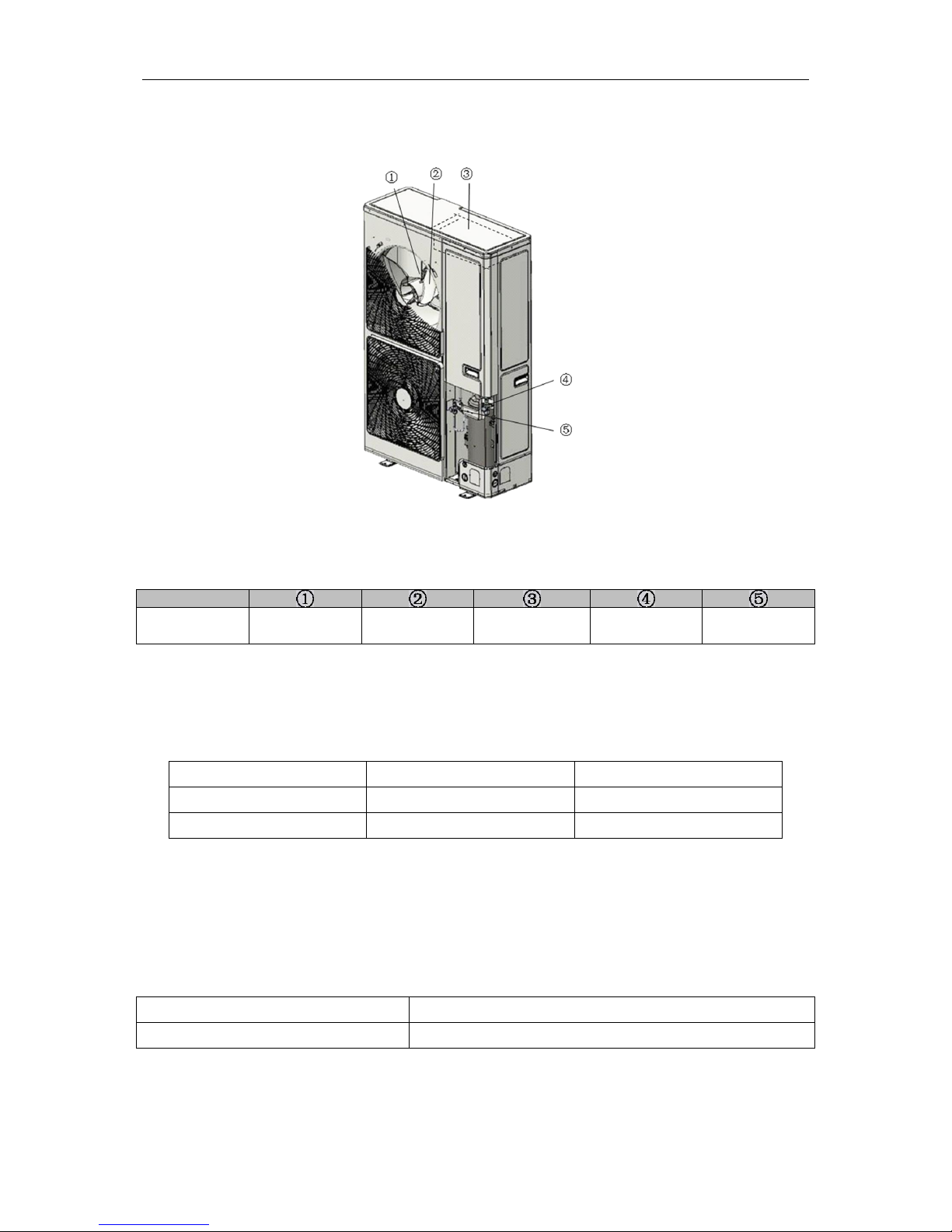
2.1 Names of Main Parts
GMV-36WL/B-T(U)
GMV-48WL/B-T(U)
Fig.1
No.
Name
Motor
Fan blade
Electric box
assembly
Gas pipe valve
Liquid pipe
valve
2.2 Combinations of Indoor and Outdoor Units
(1)
See below the number of indoor units that can be connected to the outdoor unit.
(2)
The total capacity of indoor units should be within 50%~100% of the outdoor unit.
Model
Min sets of connectable IDUs
Max sets of connectable IDUs
GMV-36WL/B-T(U)
2
5
GMV-48WL/B-T(U)
2
6
(3)
Outdoor units of DC Inverter Multi VRF System can be connected to various indoor
units. When any one of the indoor units receives operating command, outdoor unit will
start operation as per required capacity. When all indoor units stop, outdoor unit will be
shut off.
2.3 Operating Range
Cooling
Outdoor temperature: 10℃~54℃(50℉~129℉)
Heating
Outdoor temperature: -35℃~27℃(-31℉~81℉)
3 Preparation before Installation
NOTICE! Graphics here are only for reference. Please refer to actual products.
Ultra Heat GMV5 User Manual
4
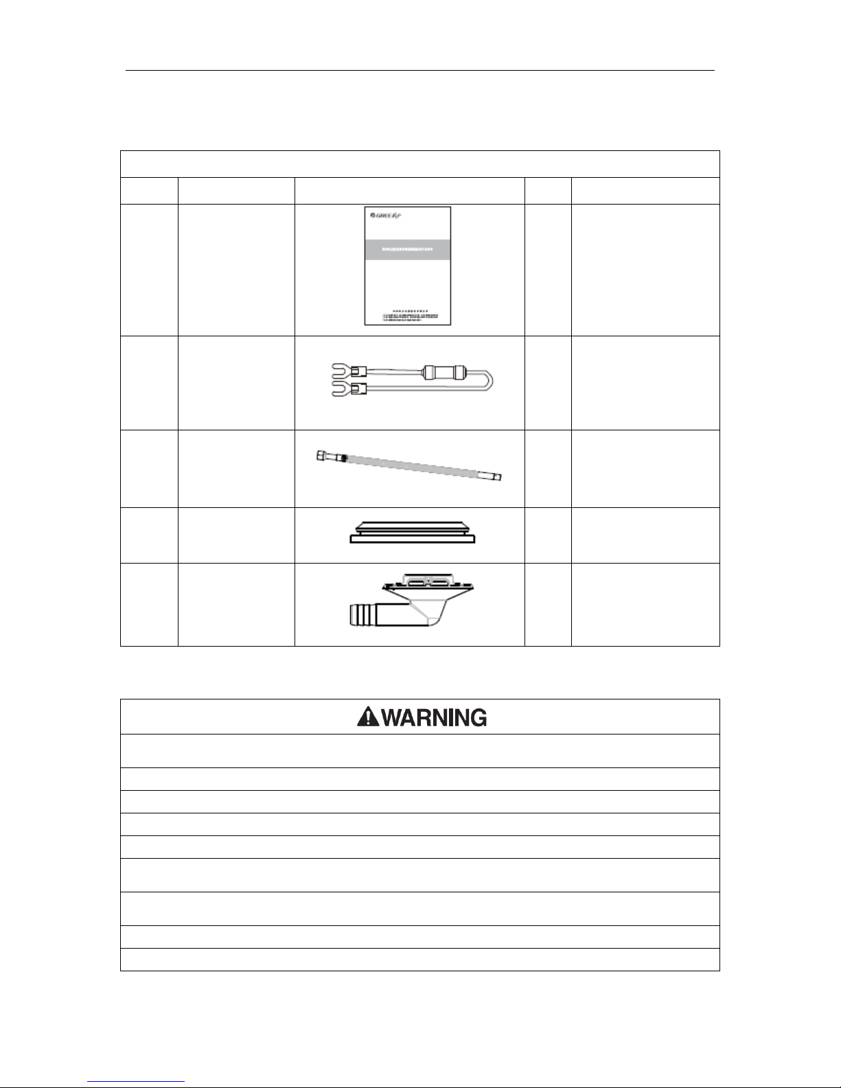
3.1 Standard Parts
Please use the supplied standard parts as required.
Parts for Outdoor Unit
No.
Name
Appearance
Qty
Remark
1
User Manual
1
2
Wiring (match
with resistance)
1
Must be connected to
the last IDU of
communication
connection
3
Corrugated pipe
1
4
Drainage hole
cap
3
5
Drainage jiont
1
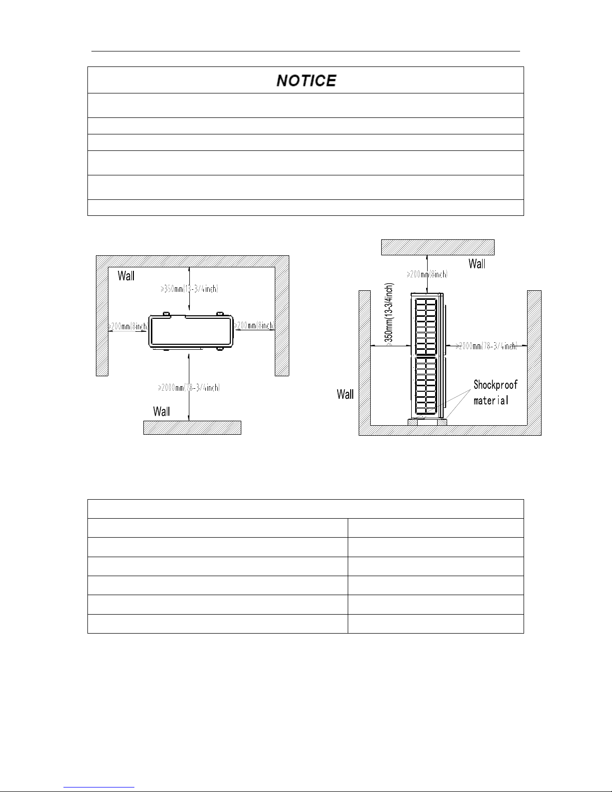
3.2 Installation Site
(1) The unit must be installed where strong enough to withstand the weight of the unit and fixed securely, otherwise
the unit would topple or fall off.
(2) Do not install where there is a danger of combustible gas leakage.
(3) Do not install the unit near heat source, steam, or flammable gas.
(4) Children under 10 years old must be supervised not to operate the unit.
(5) Select a location which is out of children’s reach. Keep the unit away from children.
(6) Make sure the location has space for heat exchange and maintenance so that unit can operate reliably with
good ventilation.
(7) Make sure the location has space for heat exchange and maintenance so that unit can operate reliably with
good ventilation.
(8) Install the unit where it will not be tilted by more than 5°.
(9) During installation, if the outdoor unit has to be exposed to strong wind, it must be fixed securely.
Ultra Heat GMV5 User Manual
5
(1) If possible, do not install the unit where it will be exposed to direct sunlight. (If necessary, install a blind that
does not interfere with the air flow.)
(2) Install ODU in a place where it will be free from getting dirty or getting wet by rain as much as possible.
(3) Install ODU where it is convenient to connect IDU.
(4) ODU and IDU should stay as close as possible to shorten the length of refrigerant pipe and reduce bend
angles.
(5) Install ODU where the condensate water can be drained out freely during heating operation. Do not place
animals and plants in the path of the warm air.
(6) Take the air conditioner weight into account and select a place where noise and vibration are small
If the ODU is totally surrounded by walls, please refer to the following figures for space dimension:
Fig.2
3.3 Piping Work Requirements
Refer to the table below for piping work requirements:
R410A Refrigerant System
Outer diameter (mm/inch)
Wall thickness(mm/ inch)
Φ6.35(Φ1/4)
≥0.8(1/32)
Φ9.52(Φ3/8)
≥0.8(1/32)
Φ12.7(Φ1/2)
≥0.8(1/32)
Φ15.9(Φ5/8)
≥1.0(1/25)
Φ19.05(Φ3/4)
≥1.0(1/25)
4 Installation Instruction
NOTICE! Graphics here are only for reference. Please refer to actual products.
Ultra Heat GMV5 User Manual
6
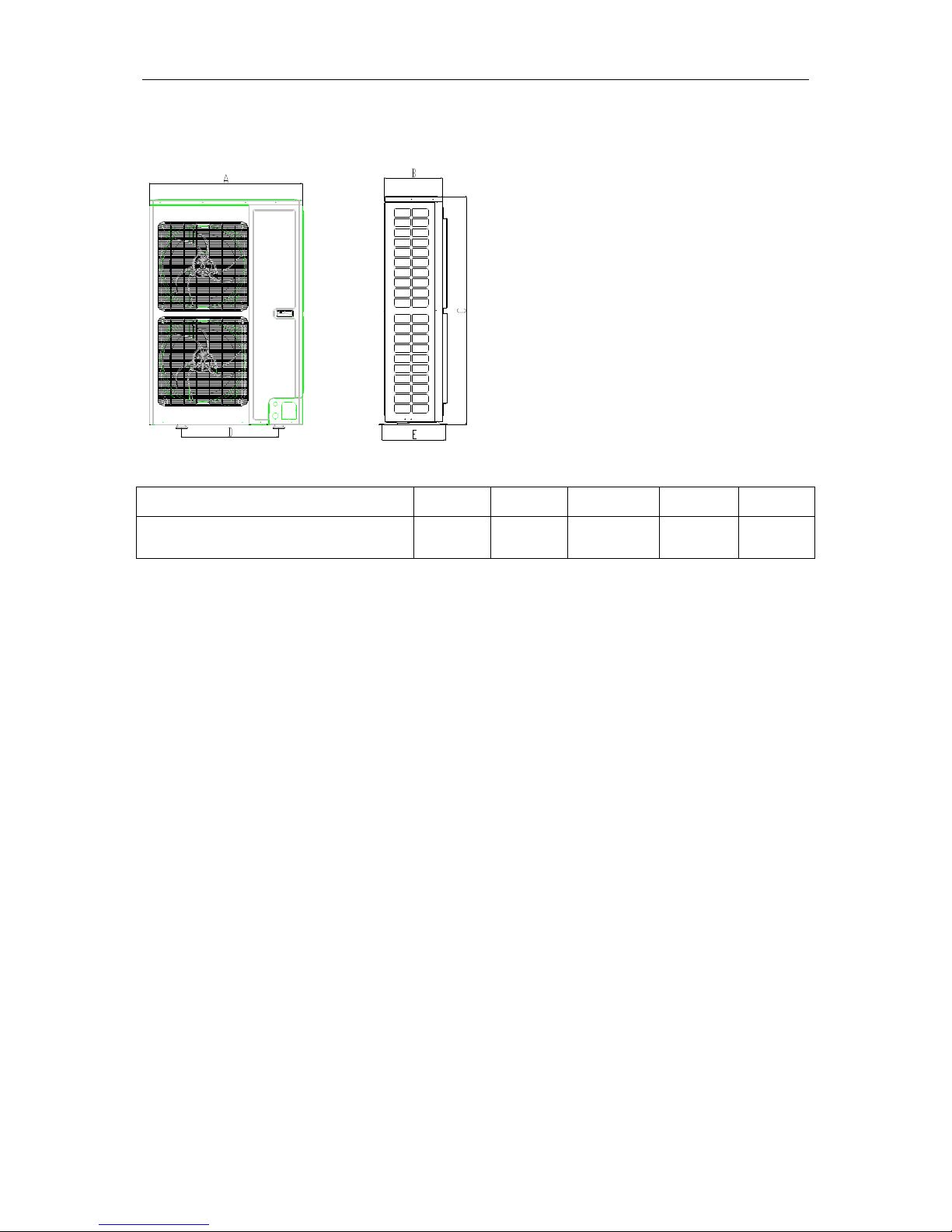
4.1 Dimension of Outdoor Unit and Mounting Hole
Unit Outline and Installation Dimension:
Fig.3
Unit:mm(inch)
Model
A B C D E
GMV-36WL/B-T(U)
GMV-48WL/B-T(U)
900
(35-3/8)
340
(13-3/8)
1345
(53)
572
(22-1/2)
378
(15)
Ultra Heat GMV5 User Manual
7
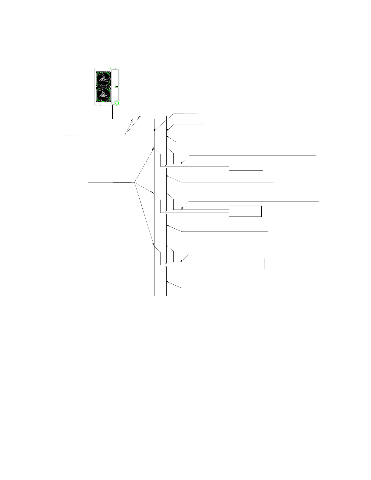
4.2 Connection Pipe
4.2.1 Schematic Diagram of Piping Connection
IDU 1
IDU 2
IDU 3
Outdoor connection pipe
Liquid pipe
Branchs of IDUs
Connection pipe between ODU and the first indoor branch
Connection pipe between indoor branch and IDUs
Connection pipe between indoor branch and IDUs
Connection pipe between indoor branch and IDUs
Connection pipe of indoor branchs
Connection pipe of indoor branchs
Branchs of IDUs
ODU
Gas pipe
Fig.4
4.2.2 Allowable Length and Height Difference of Connection Pipe
Y type branch joint is adopted to connect indoor and outdoor units. Connecting method is
shown in the figure below:
NOTICE! Equivalent length of one Y-type branch is 0.5m(1-5/8feet).
 Loading...