

Gree GMV-36WL/A-T(U), GMV-60WL/A-T(U), GMV-48WL/A-T(U) User Manual
DC INVERTER SIDE DISCHARGE VRF Ⅱ
FOR NORTH AMERICA

CONTENTS
PRODUCT ..................................................................................................................................................... 2
1 PRODUCT LIST ................................................................................................................................................ 2
2 PRODUCT FEATURES ................................................................................................................................... 2
3 SPECIFICATIONS ............................................................................................................................................ 3
4 PRODUCT CAPACITY CORRECTION ......................................................................................................... 4
5 PRINCIPAL OF OPERATION ......................................................................................................................... 6
CONTROL ..................................................................................................................................................... 9
1 UNITS’ CONTROL ............................................................................................................................................ 9
2 WIRED CONTROLLER ................................................................................................................................. 12
3 REMOTE CONTROLLER ............................................................................................................................. 18
4 MONITORING SOFTWARE .......................................................................................................................... 20
INSTALLATION ...................................................................................................................................... 65
1 ENGINEERING INSTALLATION PREPARATION AND NOTICE ........................................................... 65
2 INSTALLATION MATERIALS SELECTION ............................................................................................... 66
3 INSTALLATION OF OUTDOOR UNIT ........................................................................................................ 68
4 INSTALLATION OF ELECTRONIC EXPANSION VALVE ASSY (UNIT WITH EXTERNAL EXV) .... 71
5 INSTALLATION OF REFRIGERANT PIPELINE ....................................................................................... 71
6 INSTALLATION OF CONNECTION PIPE .................................................................................................. 75
7 ELECTRIC WIRING ....................................................................................................................................... 83
8 DEBUGGING OF UNIT .................................................................................................................................. 85
MAINTENANCE ..................................................................................................................................... 92
1 MALFUNCTION LIST .................................................................................................................................... 93
2 TROUBLESHOOTING ................................................................................................................................... 95
3 POWER DISTRIBUTION OF UNIT ............................................................................................................ 105
4 REMOVAL OF PARTS ................................................................................................................................. 108
5 COMMON MAINTENANCE ........................................................................................................................ 121
6 EXPLODED VIEW OF UNIT AND PARTS’ LIST ..................................................................................... 126

DC Inverter Side Discharge VRF Ⅱ for North America
PRODUCT
1

DC Inverter Side Discharge VRF Ⅱ for North America
Model
Product
Code
Cooling
Capacity
Heating
Capacity
Power
Supply
Refrigerant
Appearance
Kw(Btu/h))
Kw(Btu/h
GMV-36WL/A-T(U)
CN850W
0230
11
(37500)
12.3
(42000)
208/230V
~
60Hz
R410A
GMV-48WL/A-T(U)
CN850W
0220
14.1
(48000)
15.8
(54000)
GMV-60WL/A-T(U)
CN850W
0270
17.6
(60000)
18.7
(64000))
PRODUCT
1 Product List
2 Product Features
2.1 General introduction
Gree DC Inverter Multi VRF System II is the latest generation of DC inverter units.
One set of air-cooled outdoor unit can be connected with multiple direct evaporation
indoor units that are of the same or different forms and capacity. This refrigerating system
can directly provide air conditioning for one or more areas, and is applicable for residential
and light commercial uses. It features high energy efficiency, strong anti-interference
capability, long connectable pipe, wide operation range, good sound quality, intelligent
capacity regulation, complete protection, etc.
2.1.1 Features
(1)
complete direct current and upgrade the energy efficiency. SEER is up to 16; HSPF of
GMV-36WL/A-T(U) and GMV-48WL/A-T(U) is up to 9; HSPF of GMV-60WL/A-T(U) is up
to 8.2.
(2)
anti-interference capability is stronger and the control on indoor units is more accurate,
Super high energy efficiency
The 2nd generation of DC Inverter Multi VRF System adopts DC motor to realize
New generation CAN bus communication
Due to the latest communication method—CAN Bus Communication, system’s
with higher reliability. Specialized shield wire is no more needed and ordinary
communication wire can be applied in the construction, which has increased the
installation flexibility.
(3)
Long connection pipe
2
DC Inverter Side Discharge VRF Ⅱ for North America
Model
GMV-36WL/A-T(U)
GMV-48WL/A-T(U)
GMV-60WL/A-T(U)
Cooling capacity
kW
11
14.1
17.6
Btu/h
37500
48000
60000
Heating capacity
kW
12.3
15.8
18.7
Btu/h
42000
54000
64000
Circulating air
volume
m3/h
6000
6300
7800
CFM
3532
3708
4601
Noise
dB(A
)
55
56
63
Refrigerant charge
volume
Kg
5 5 6.5
oz
176
176
229
Power supply
208/230V~60Hz
208/230V~60Hz
208/230V~60Hz
Rated
power
input
Coolin
g
kW
3.25
4.47
6.45
Heatin
g
kW
3.72
3.93
5.60
Unit Dimensions
(WxDxH)
mm
900×340×1345
940×320×1430
inch
35_7/16×13_3/8×53
37×12_9/16×56_1/4
Dimensions
mm
998×458×1515
1033×433×1580
The maximum length of connection pipe is 300m(984ft) (in total) and the farthest
connection pipe between indoor and outdoor units can be 120(394ft)m’s long, which has
extended the installation condition and reduced the limit of installation distance.
(4)
Wide operation range
Units can operate reliably in a wide temperature range (cooling: -5~48℃(23~118°F),
heating: -20~27
(5)
Fine sound quality
-4~81°F))
℃(
Through a series of optimized measures, system has reduced the throttle noise and
oil return noise of indoor units, gas bypass noise, etc. so that units are more comfortable
regarding sound quality.
(6)
Intelligent PID capacity regulation
With the independently developed PID capacity regulation technology, units are able
to control the indoor ambient temperature more quickly and reduce the fluctuation of room
temperature.
(7)
Complete protection
Units are equipped with a series of protection to accurately identify errors and protect
the units, which has ensured reliable and safe operation.
3 Specifications
3.1Outdoor Unit
3
DC Inverter Side Discharge VRF Ⅱ for North America
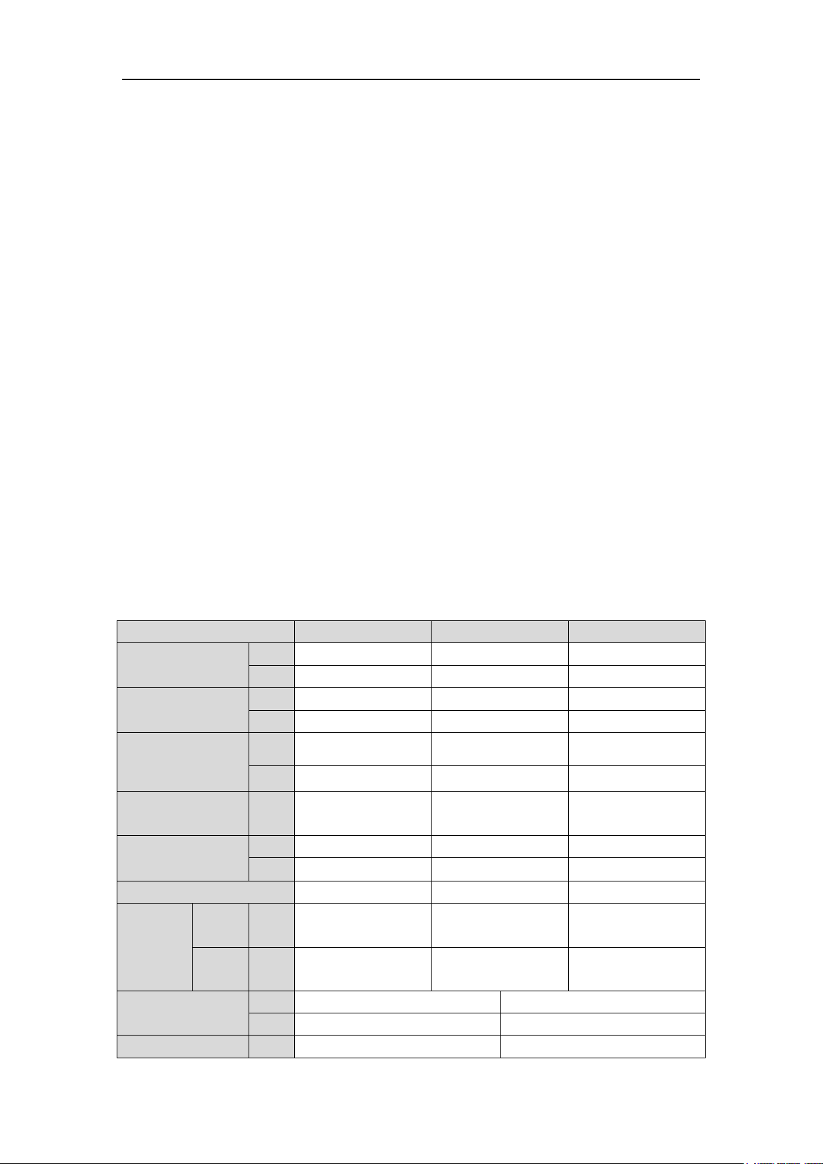
Model
GMV-36WL/A-T(U)
GMV-48WL/A-T(U)
GMV-60WL/A-T(U)
(WxDxH)
inch
39_5/16×18×59_5/8
40_5/8×17×62_3/16
Compressor
QXAS-F428zX050A
LNB53FCFMC
Water-proof level
IPX4
IPX4
IPX4
Suitable climite
T1
T1
T1
Connectio
n pipe
Gas
mm
Φ15.9
Φ15.9
Φ19.05
inch
Φ5/8
Φ5/8
Φ3/4
Liquid
mm
Φ9.52
Φ9.52
Φ9.52
inch
Φ3/8
Φ3/8
Φ3/8
Connection
Method
Bell mouth connection
Bell mouth connection
Bell mouth connection
Net weight
Kg
110
110
124
oz
3880
3880
4375
Cooling
Outdoor temperature: -5~48℃ (23~118°F)
Heating
Outdoor temperature: -20℃~27℃(-4~81°F)
Note:
① Units conform to design standard: ARI 210/240.
② Specifications may be changed due to product improvement. Please refer to
nameplates of the units.
③ Noise data are collected from a semi-anechoic room. Decibels may be slightly higher
in actual operation due to environmental change.
④ Refrigerant charge volume listed in the table is based on the condition where indoor
and outdoor units are at a same level and with no connection pipe. Supplementary
refrigerant needs to be charged according to actual circumstance.
3.2 Operation range
4 Product Capacity Correction
4.1 Instruction of Product Capacity Correction
Nominal cooling capacity and nominal heating capacity are tested under given
conditions:
(1)
(2)
(3)
Rated cooling or heating condition
No height difference between indoor unit and outdoor unit
Short connection pipe
If the three conditions above have changed, the cooling and heating capacity will
change correspondingly and correction is needed.
4.2 Capacity Code
Instruction of capacity code
GMV-36WL/A-T(U) 、GMV-48WL/A-T(U) and GMV-60WL/A-T(U) are identical in
4
DC Inverter Side Discharge VRF Ⅱ for North America
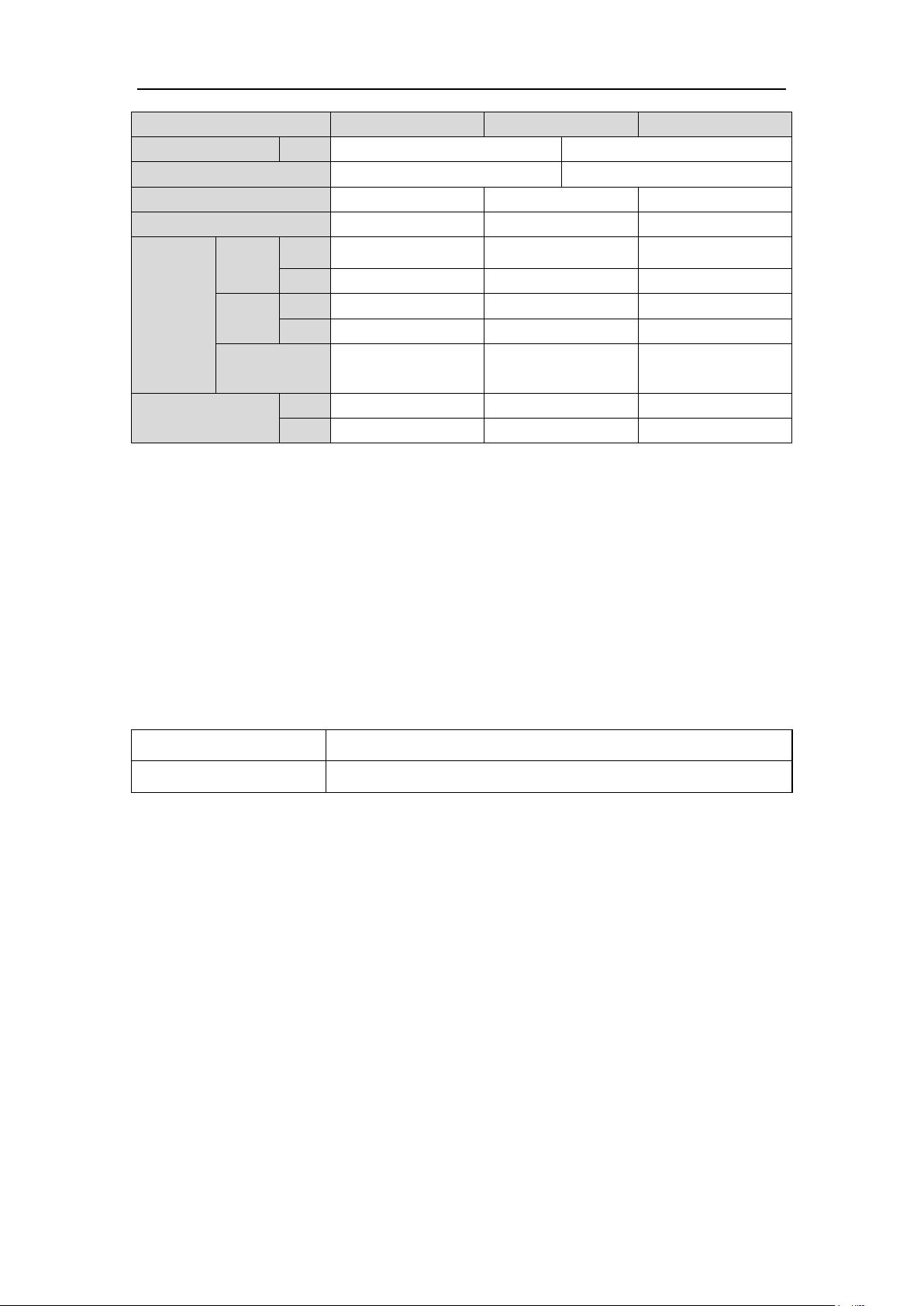
Sheet of DIP Switch (5-bit DIP switch)
Model
Bit 1
Bit 2
Bit 3
Bit 4
Bit 5
GMV-36WL/A-T(U)
0 0 1 0 0
GMV-48WL/A-T(U)
0 0 1 0 1
GMV-60WL/A-T(U)
0 1 0 0 0
Model
GMV-36WL/A-T(U)
GMV-48WL/A-T(U)
GMV-60WL/A-T(U)
Rated cooling
capacity
kW
11
14.1
17.6
Btu/h
37500
48000
60000
Rated heating
capacity
kW
12.3
15.8
18.7
Btu/h
42000
54000
64000
components, systems and structure, etc. While the required capacity is set through the
capacity DIP switch.
4.3Capacity Correction Formula
4.3.1Rated capacity of outdoor unit
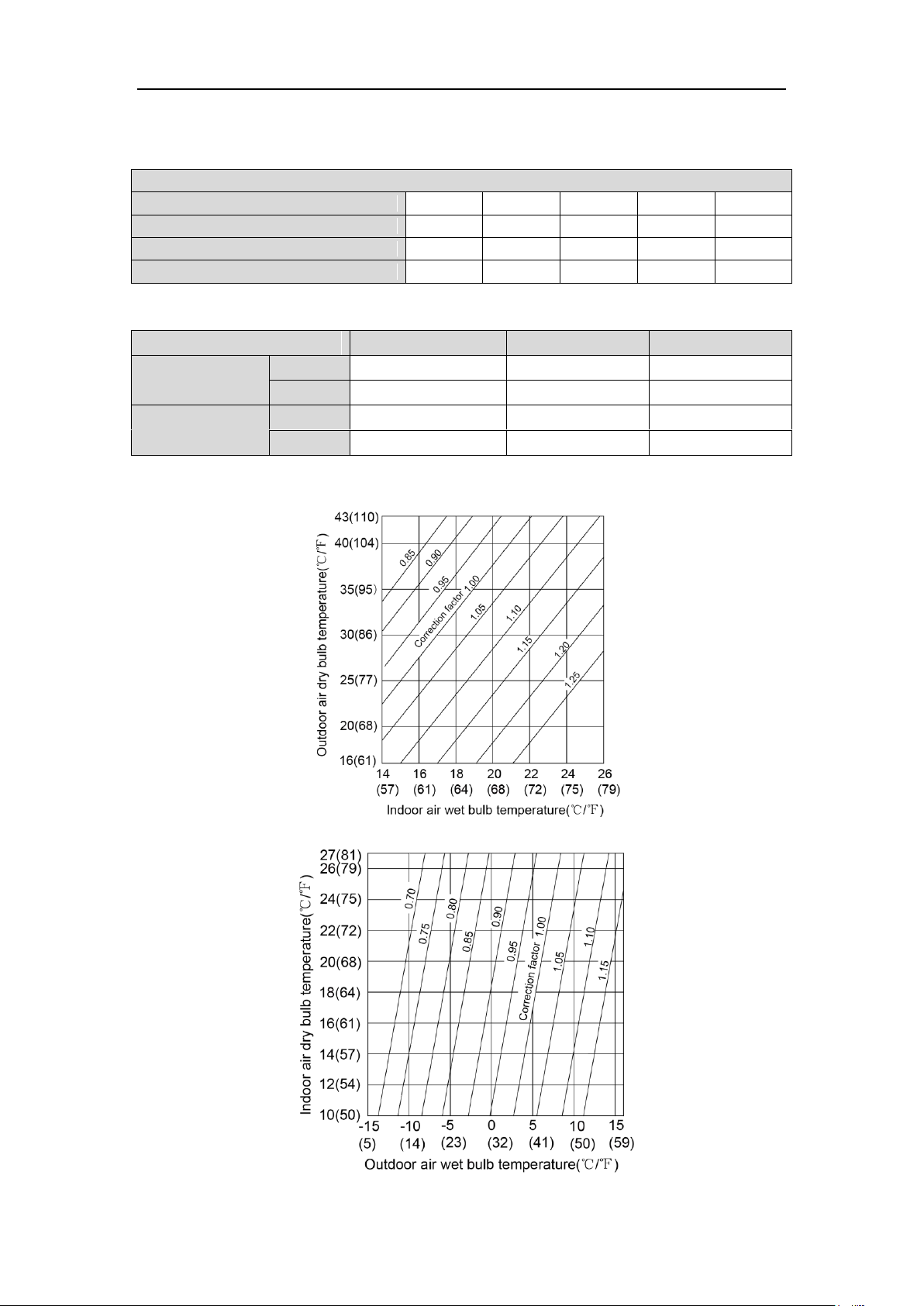
4.3.2 Correction factor of indoor and outdoor temperature
(1)
(2)
Correction factor of cooling capacity
Correction factor of heating capacity
5
DC Inverter Side Discharge VRF Ⅱ for North America
m 0 10
20
30
40
50
60
70
80
90
100
110
120
130
140
150
ft 0 33
66
98
131
164
197
230
262
295
328
361
394
427
459
492
Name
Compressor
4-way valve
Cut-off
valve
One-way valve
Capillary tube
Symbol
Name
Gas-liquid
separator
Pressure
switch
Pressure
sensor
Axial-flow finned heat
exchanger
Electronic expansion valve
Symbol
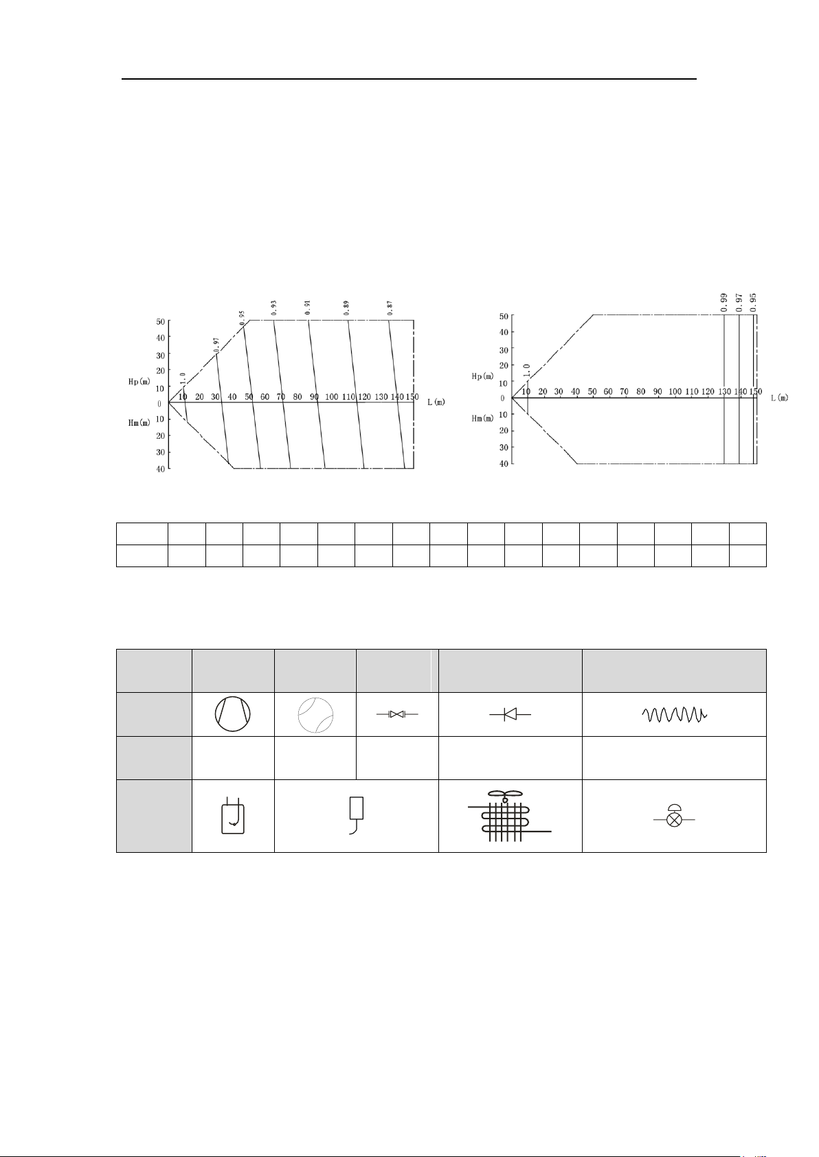
4.3.3 Correction factor of pipe length and height difference
Symbol description:
Hp:Height difference in case indoor unit is below outdoor unit(m/feet);
Hm: Height difference in case indoor unit is above outdoor unit (m/feet);
L: Length of one-way equivalent pipe
Below table shows the capacity variance ratio for 100% full load in standard working
condition (thermostat setting is 16℃(61℉) for cooling and 30℃(86℉) for heating).
Variance ratio of heating capacity
NOTE:
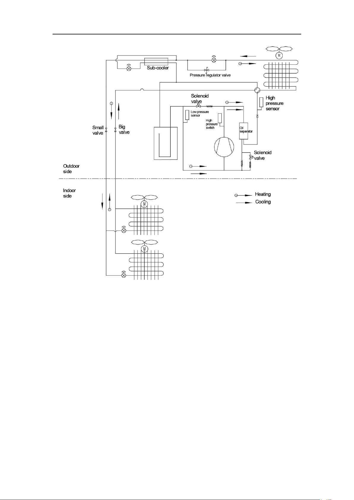
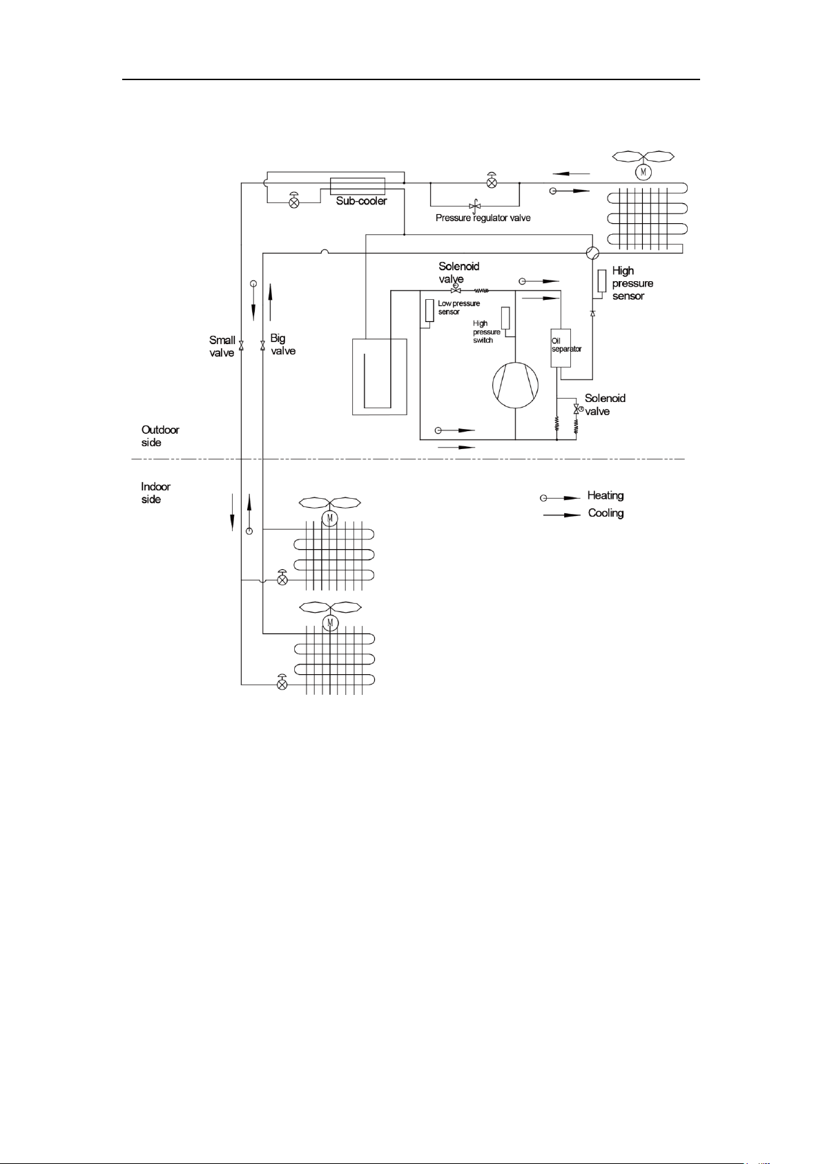
5 Principal of Operation
Components in flowcharts are presented according to the following table:
6
DC Inverter Side Discharge VRF Ⅱ for North America
In cooling, the low-temperature and low-pressure refrigerant gas from each indoor
heat exchanger will be merged and inhaled by the compressor and then become
high-temperature and high-pressure gas, which will later be discharged into outdoor heat
exchangers. By exchanging heat with outdoor air, refrigerant will turn to liquid and flow to
each indoor unit via Y-type branch or manifold. Pressure and temperature of the
refrigerant will then be lowered by throttle elements before it flows into indoor heat
exchangers. After exchanging heat with indoor air, refrigerant wil become low-temperature
and low-pressure gas again and repeat the circulation so as to realize the cooling effect.
In heating, 4-way valve will be energized to make refrigerant circulate in a reverse
direction of cooling. Refrigerant will release heat in indoor heat exchangers (electric
heating elements will also work under certain circumstance and release heat) and absorb
heat in outdoor heat exchangers circularly so as to realize the heating effect.
7

DC Inverter Side Discharge VRF Ⅱ for North America
CONTROL
8
DC Inverter Side Discharge VRF Ⅱ for North America
CONTROL
1 Units’ Control
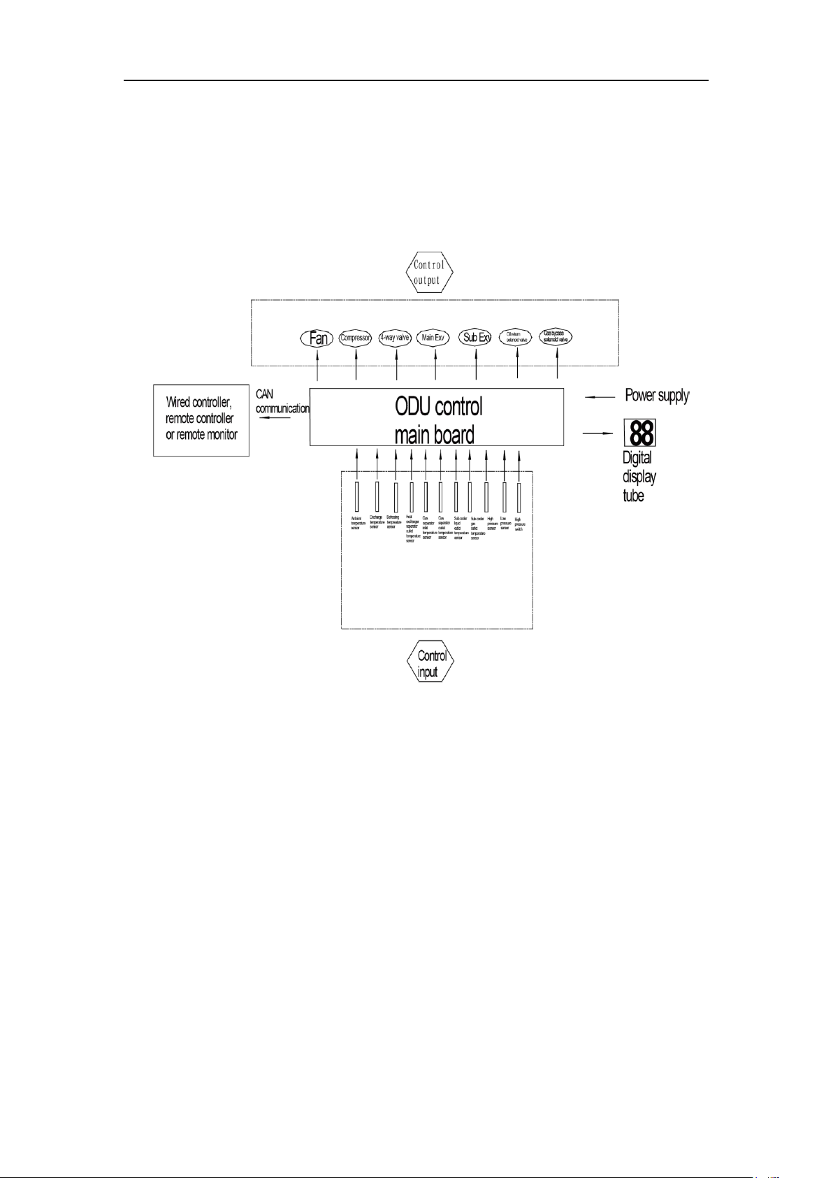
1.1 Schematic diagram of units’ control
(1) Interpretation on the schematic diagram
1) High pressure switch is used to identify system’s high and low pressure. When
pressure is too high, the switch will break off and send a signal to main board.
Main board will pass this signal to controller, where the error will be displayed, and
stop unit from working.
2) High/low pressure sensor is used to test unit’s high/low pressure and send
real-time data to controller, which will control each unit’s output according to the
control logic.
3) Temperature sensors are used to test the tube temperature of the unit and send
data to the controller, which will control each unit’s output according to the control
logic.
9
DC Inverter Side Discharge VRF Ⅱ for North America
1.2 Operation Flow Chart
1.2.1 Operation Flow Chart of Indoor Unit
1) Cooling operation
2) Heating operation
3) Drying operation
4) Operation procedure is the same as that of cooling operation
5) Fan operation
6) The EXV of the indoor unit closes in fan mode, so that there is no refrigerant flow
in the refrigerant pipe of that indoor unit. But the fan of that indoor unit operates.
10
DC Inverter Side Discharge VRF Ⅱ for North America
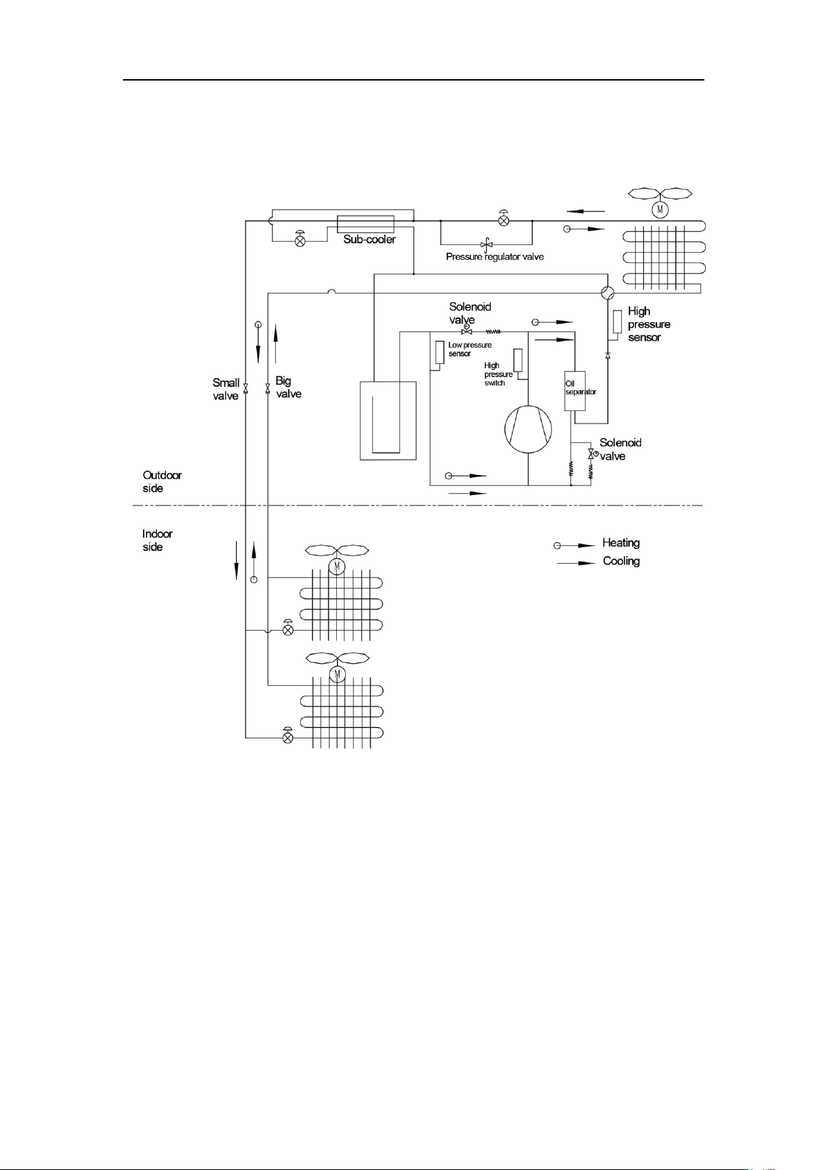
1.2.2 Operation Flow Chart of Outdoor Unit
1) Cooling operation
2) Heating operation
1.3 Unit Control Functions
1.3.1Control functions of outdoor unit
1) Include the following contents.
2) Compressor capacity output.
3) Compressor start-up control.
4) Outdoor fan control.
5) Defrosting control.
6) Heating EXV control.
7) Subcooling valve control.
8) Refrigerant lacking control.
1.3.2Control functions of indoor unit
1) Include the following contents
2) Cool
11
DC Inverter Side Discharge VRF Ⅱ for North America
3) Dry
4) Heat
5) Fan
6) Heating temperature compensation
7) Anti-freezing
8) Air swing
9) Drainage pump
10) IDU EXV
11) Static pressure level
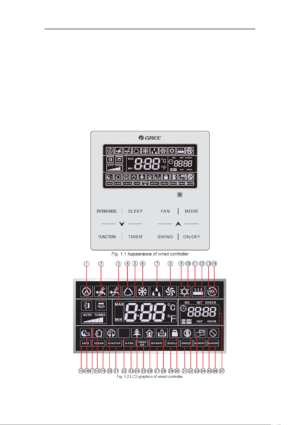
2 Wired Controller
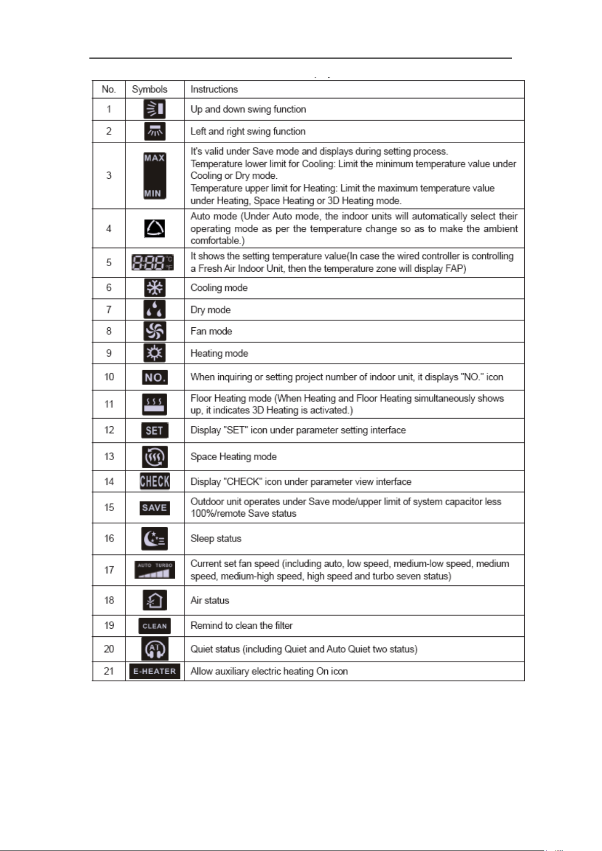
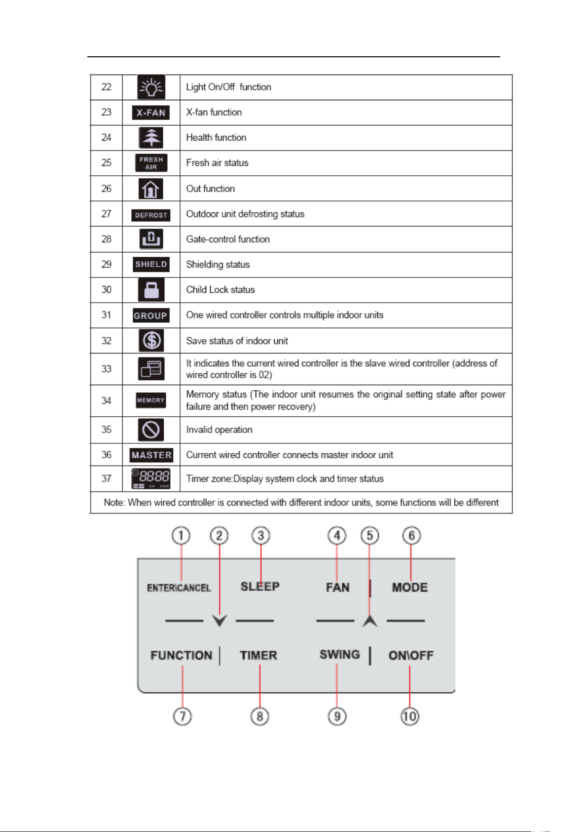
2.1 Control panel
12
DC Inverter Side Discharge VRF Ⅱ for North America
13
DC Inverter Side Discharge VRF Ⅱ for North America
Button Graphics
14
DC Inverter Side Discharge VRF Ⅱ for North America
mm
112
22
2.7
3.3 5 42.5
40
82.5
inch
4.41
0.87
0.11
0.13
0.20
1.67
1.57
3.25
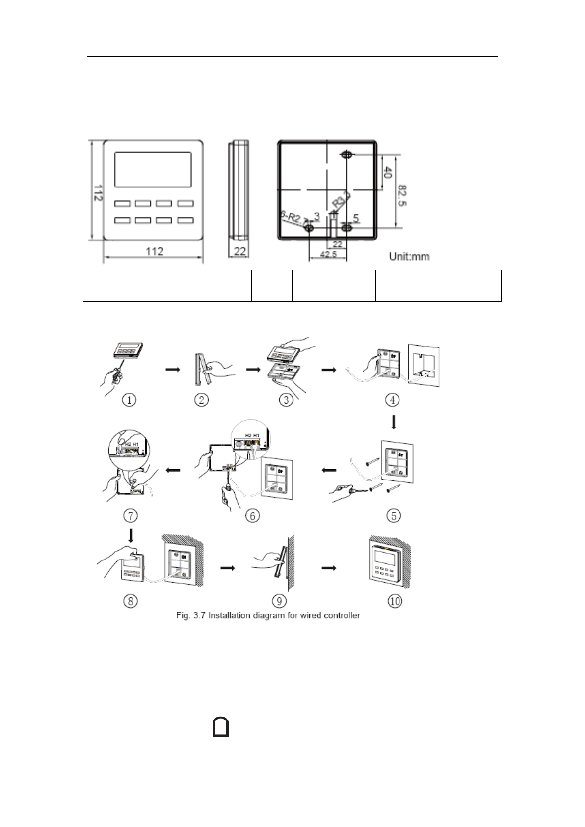
2.2 Installation and removal
2.2.1 Installation dimensions
2.2.2 Installation method
Above is a simple installation method of wired controller. Please pay attention to the
following:
1) Before installation, disconnect power of the indoor unit. Do not operate when
power is connected.
2) Pull out the 2-core twisted pair cable from the installation hole on the wall and lead
it through the hole on the back plate of wired controller.
15
DC Inverter Side Discharge VRF Ⅱ for North America
If caliber of the communication cord is too large, which causes difficulty in leading or sticking the cord
according to above point 2 and point 5, strip some of the sheath of the communication cable to meet the
installation requirement.
3) Place the wired controller on wall and secure its back plate on wall with screw
M4X25.
4) Connect the 2-core twisted pair cable to terminal H1 and terminal H2. Tighten up
the screws.
5) Stick the cable in the slot that is left of the terminals and buckle the wired
controller’s panel with its back plate.
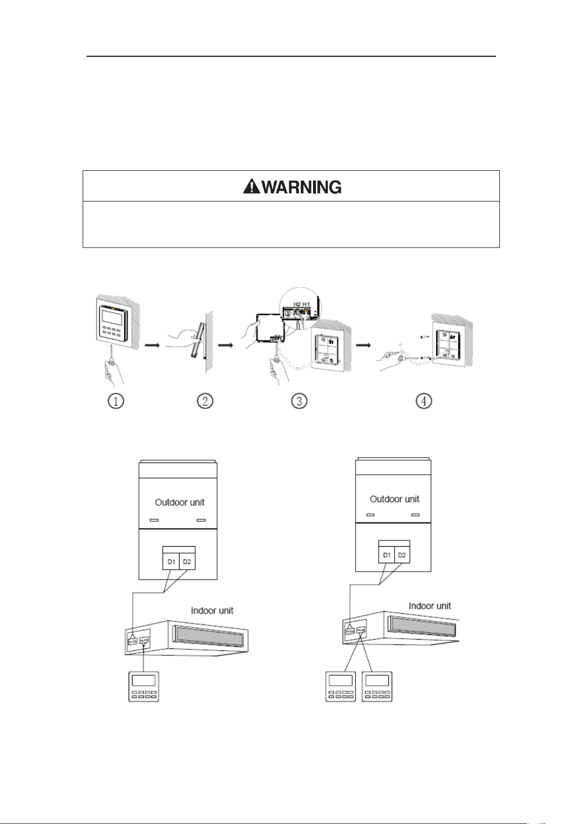
2.2.3 Removal method
Fig.2.1.3 Removal of Wired Controller
2.2.4 Connection of communication cord
There are 4 ways to connect wired controller with indoor units’ network:
Fig. 2.2.4.1 One wired controller Fig. 2.2.4.2 Two wired controllers
control one indoor unit controls one indoor unit
16
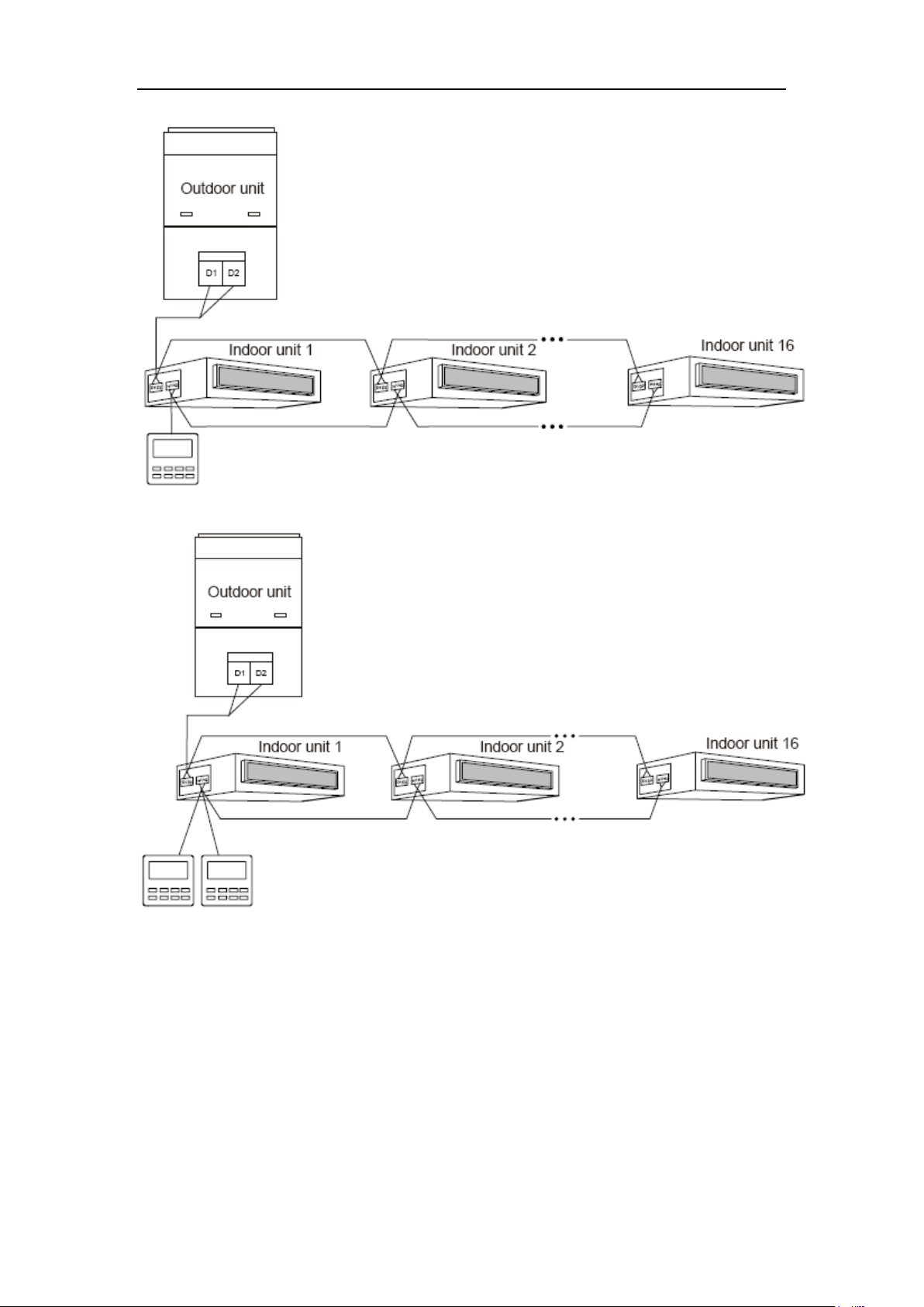
DC Inverter Side Discharge VRF Ⅱ for North America
Fig. 2.2.4.3 One wired controller controls multiple indoor units simultaneously.
Fig. 3.6Two wired controllers control multiple indoor units simultaneously.
17
DC Inverter Side Discharge VRF Ⅱ for North America
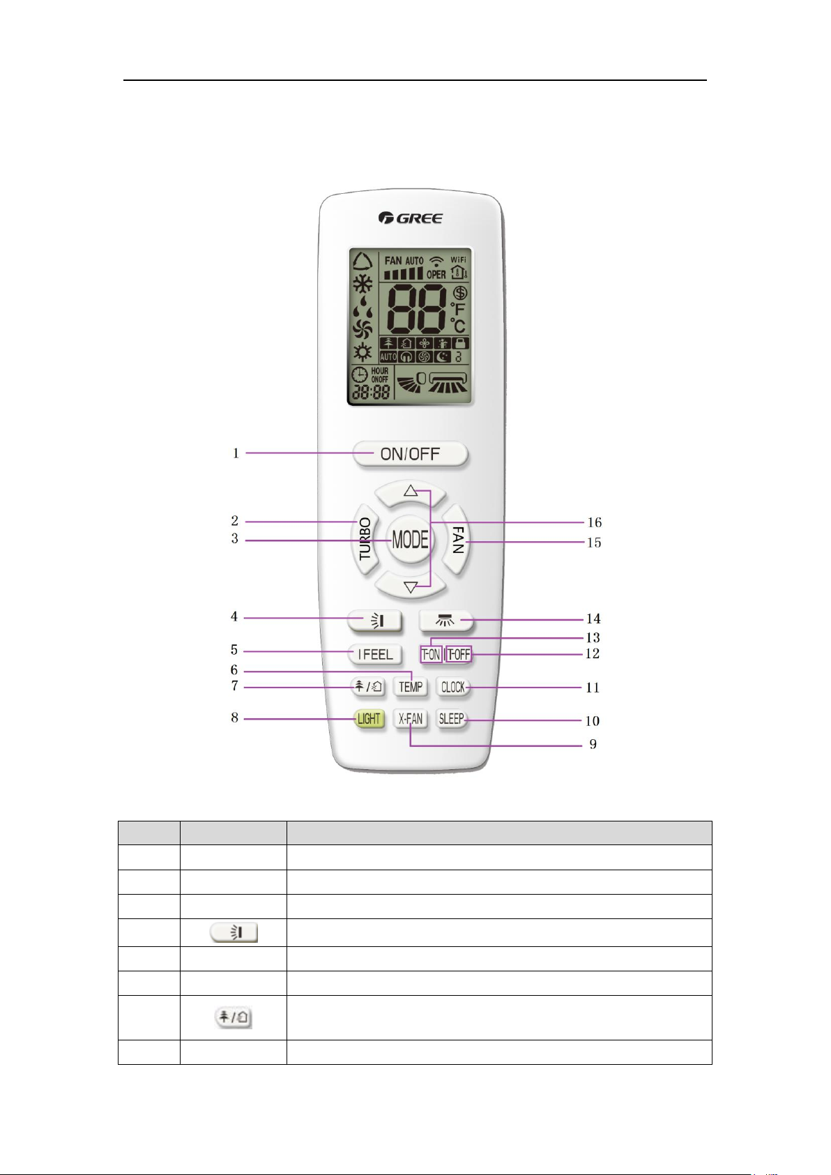
No.
Button name
Function
1
ON/OFF
Turn on or turn off the unit
2
TURBO
Set turbo function
3
MODE
Set operation mode
4
Set up&down swing status
5
I FEEL
Set I FEEL function
6
TEMP
Switch temperature displaying type on the unit’s display
7
Set health function and air function
8
LIGHT
Set light function
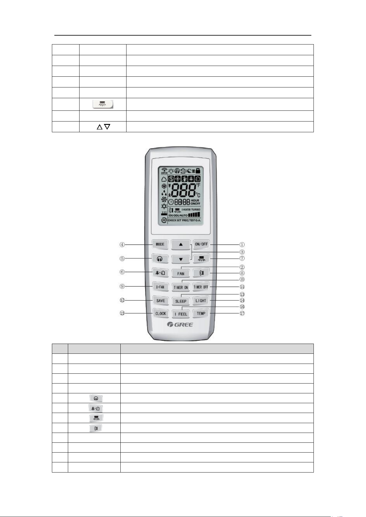
3 Remote Controller
(1) Remote controller YAP1F
Button name and function introduction
18
DC Inverter Side Discharge VRF Ⅱ for North America
9
X-FAN
Set X-FAN function
10
SLEEP
Set sleep function
11
CLOCK
Set clock of the system
12
TOFF
Set timer off function
13
TON
Set timer on function
14
Set left&right swing status
15
FAN
Set fan speed
16
/
Set temperature and time
No.
Button name
Function
1
ON/OFF
Turn on or turn off the unit
2
FAN
Set fan speed
3
▲/▼
Set temperature and time
4
MODE
Set operation mode
5 Set quiet function
6
Set health function and air function
7 Set left&right swing status
8 Set up&down swing status
9
X-FAN
Set X-FAN function
10
TIMER ON
Set timer on function
11
TIMER OFF
Set timer off function
12
SAVE
Set energy-saving function
(2) Remote controller YV1L1
19
DC Inverter Side Discharge VRF Ⅱ for North America
13
SLEEP
Set sleep function
14
LIGHT
Set light function
15
CLOCK
Set clock of the system
16
I FEEL
Set I FEEL function
17
TEMP
Switch temperature displaying type on the unit’s display
4 Monitoring Software
4.1 Function introduction
With the rapid development of building complex, more and more central air
conditioners in various models are used in different places, resulting in inconvenience for
the management of air conditioners. Integrating with telecommunication technology and
computing software, Gree Commissioning Tool Kits can realize the comprehensive
monitor, control and commissioning on central air conditioners. It is an efficient solution for
the management of central air conditioners that are separated in different parts of a
building. Administrator doesn’t need to control every unit on site, but rather controls the
units by just sitting in front of a computer. This will not only improve the productivity, but
also reduce cost on human resources, property and management.
Gree Commissioning Tool Kits can monitor and control the 2nd generation of Gree
Multi VRF. User can monitor and control units by monitoring the computer. This software is
an efficient tool for the intelligent air conditioning management as well as installation and
after-sales service and commissioning. It can debug units and control units’ operation
status quickly and conveniently. It will not only improve the productivity but also reduce the
difficulty and cost of commissioning and maintenance, providing better and faster service
to customers.
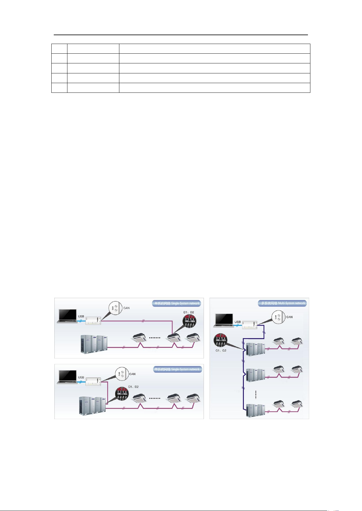
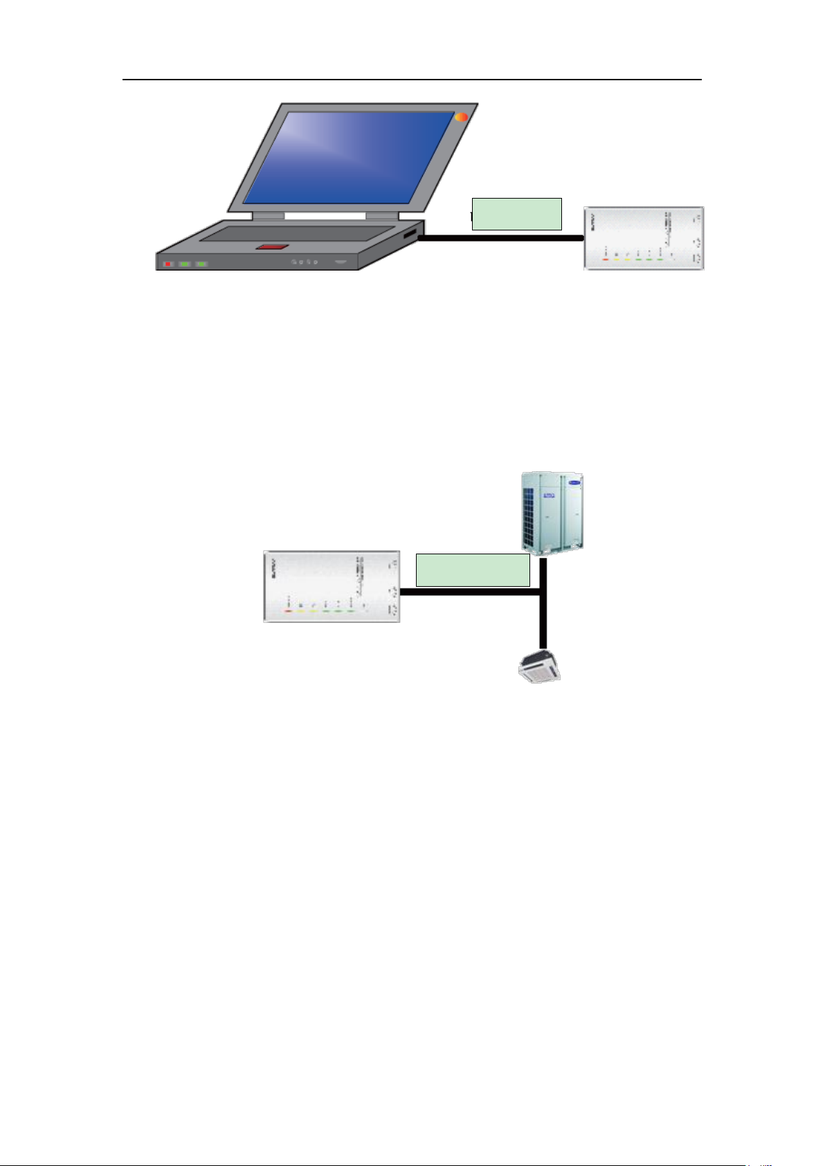
4.2 Connection of computer and units
It can be connected with single-system network or multi-system network. In the
single-system network, indoor units or outdoor units are connectable, while in the
multi-system network, only the master outdoor unit can be connected.
Seen from the diagram, Gree commissioing network is made up of 3 parts:
20
DC Inverter Side Discharge VRF Ⅱ for North America
Name
Model
Material no.
Remark
Gree USB data converter
MC40-00/B
30118027
Convert the air conditioning
communication into computing
communication
Gree Commissioning Tool
Kits (CD-ROM)
DG40-33/A(C)
36400000003
Include Gree debugger, monitoring
software, USB driver and USB
converter configuring software.
USB wire
\
40020082
Wire connecting computer’s USB
interface and converter
Communicaiton board
\
30118015
This board can be used when units
are far from the computer.
Board connection wire (1m)
\
4001023229
4-core wire connecting units and
converter
Board connection wire
(5.5m)
\
4001023214
4-core wire connecting units and
converter
Instruction manual
\
64134100023
Instruction manual
The 1st part is the monitoring computer, including Gree debugger and Gree USB
converter driver that are installed in the computer.
The 2nd part is Gree USB converter, which is to convert the air conditioning
communication into computing communication. This part is made up of Gree USB data
converter and USB data wire.
The 3rd part is air conditioners, including outdoor units, indoor units and the
connection wires. If connection wire is not long enough, it’s OK to connect via the patching
board of the commissioning tool kits. In a single-system network, both indoor units and
outdoor units can be connected, while in a multi-system network, only the master outdoor
unit can be connected.
4.3 Parts introduction
4.3.1 List of parts
4.3.2 Gree USB data converter
4.3.2.1 Functions introduction
Gree USB data converter will convert the RS485, HBS and CAN commucation within
the air conditioners into the communication that is recognizable by computer’s USB
interface.
21
DC Inverter Side Discharge VRF Ⅱ for North America
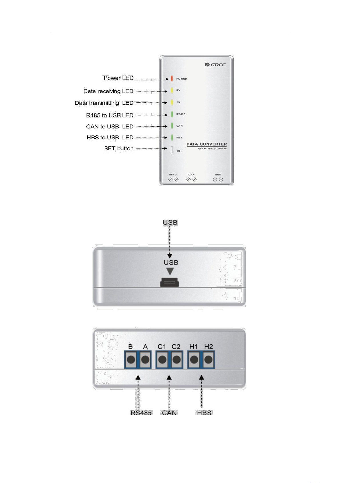
4.3.2.2 Appearance
22

DC Inverter Side Discharge VRF Ⅱ for North America
4.3.2.3 Operation instruction
(1) Power LED: a red light. If the red light is on, it indicates normal power supply. If the
red light is off, it indicates the power supply of converter is not normal.
(2) Communication LEDs: yellow lights. When converter is working and the computer is
transmitting data, the TX data transmitting light will be flickering. When units are
uploading data to the computer, the RX data receiving light will be flickering.
(3) When converter is under RS485 data transferring mode, the function LED of RS485
to USB will be on.
(4) When converter is under CAN data transferring mode, the function LED of CAN to
USB will be on.
(5) When converter is under HBS data transferring mode, the function LED of HBS to
USB will be on.
(6) USB interface: connect USB data wire.
(7) CAN interface: When converter is under CAN communication mode, connect air
conditioner’s CAN data interface. CAN interface exhibits no polarity (A and B are
equal).
(8) HBS interface: When HBS converter is under HBS communication mode, connect air
conditioner’s HBS data interface. HBS interface exhibits no polarity (This interface is
not yet available for Gree debugger and the monitoring software).
(9) RS485 interface: When RS485 converter is under RS485 communication mode,
connect air conditioner’s RS485 data interface. RS485 interface exhibits polarity and
terminal A and B are different.
4.3.2.4 Installation notice
(1) Install indoors. To avoid collision, it is suggested to place it in the monitoring room
together with the computer.
(2) No need of power supply. Power is supplied through computer’s USB interface.
4.3.3 Communication board
Communication board is mainly used for transferring data. It functions similar with a
patching board. Provided that units are far away from the monitoring computer,
communication board can be used for connection.
4.3.4 Communication cord
4.3.4.1 USB wire
(1) Connect USB wire with computer’s USB interface at one end and with the USB
interface of USB data converter at the other end, as indicated below:
23
DC Inverter Side Discharge VRF Ⅱ for North America
USB Wire
Board Connection Wire
4.3.4.2 Board Connection Wire
(1) There are 2 board connection wires supplied for the commissioning tool kits. One is 1
meter’s long and the other is 5.5 meters’ long. They are only different in length. One
end of the wire shall connect with air conditioner’s communication interface and the
other end shall connect with CAN interface of Gree USB converter. As shown below,
the wire can be connected to the communication interface of outdoor unit or the
communication interface of indoor unit:
4.4 Software introduction
(1) One-button commissioning
Personnel responsible for the commissioning of air conditioners can start
commissioning by pressing one button according to the commissioning logic of
software, which will give the commissioning order to units. Then commissioning will
be started up automatically step by step. During the commissioning, the
corresponding process will be ticked in green on the software interface. If any
commissioning process is not normal, it will be displayed in red.
(2) Comprehensive monitoring
The software can monitor every part of the air conditioning system, including
functions, equipment and components operating status. The monitoring results will be
displayed in text or curve so that user can acquire the operating status of the entire
system conveniently and straightforwardly.
(3) Real-time control
24
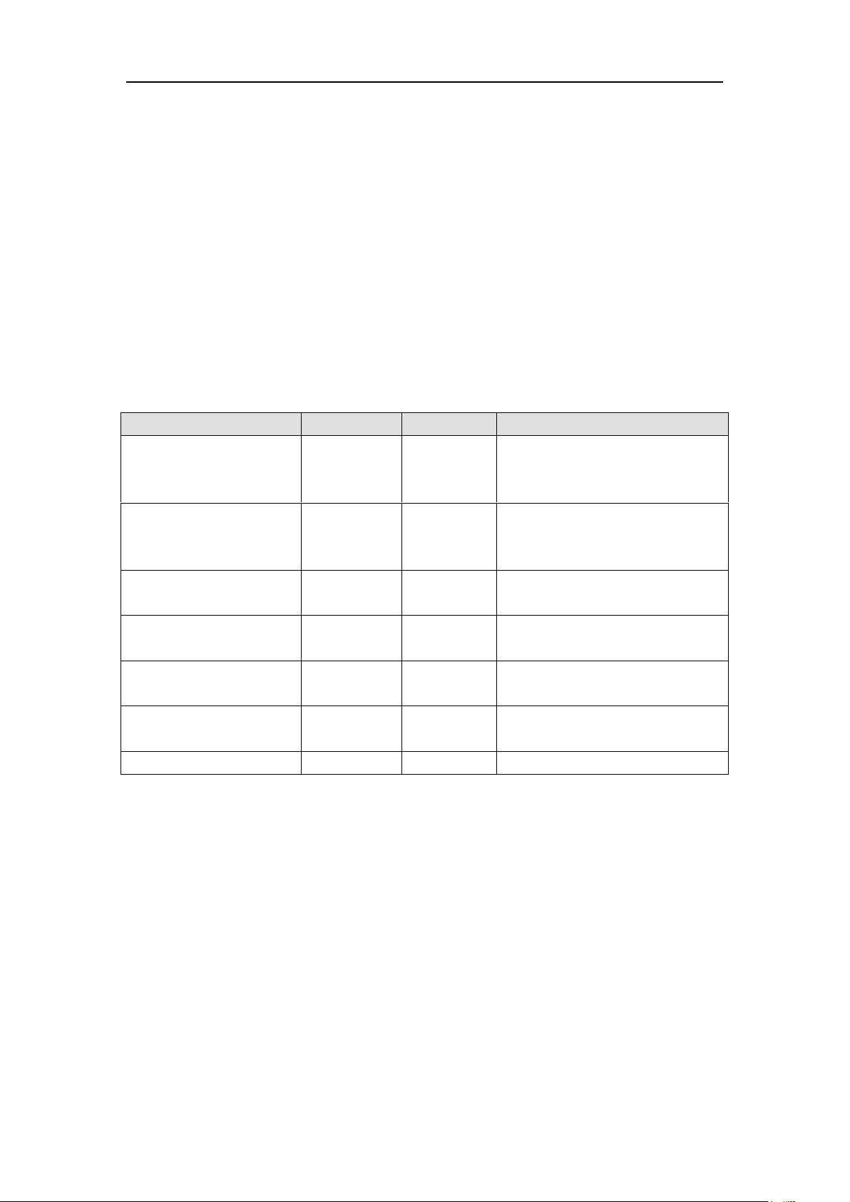
DC Inverter Side Discharge VRF Ⅱ for North America
Memory
1 GB at least
2 GB or above is preferred
Hard Disc
10 GB available
CPU
Core 2 or higher
1 GHz at least
2 GHz or above is preferred
Operation System
Windows Server 2003 SP3 or higher
Windows XP SP3 or higher
Windows Vista
Windows 7
Air conditioner’s operating time and requirements may be different based on areas
and functions. User can set units’ parameters on computer according to actual needs,
such as the on/off, temperature, fan speed, mode, etc. Meanwhile, the software can
also set or view the function parameters of outdoor units, gateway and other
equipment. In this way, the mangement of central air conditioners is realized.
(4) Replay history
Software can replay and save the historical monitoring information in the data base.
The replay speed can be selected and the information will be shown in text or curve.
This function has greatly saved the time to track problem cause and resolved the
difficulty of problem reproduction.
(5) Applicable to multiple series, models and users
Gree Commissioning Tool Kits is applicable to air conditioning system that comsists
of multiple series and models. Later, it will be developed to cover all series of Gree
central air conditioners, such as multi VRF, centrifugal chiller, screw type chiller,
ground source heat pump units, modular units, fan coiled units, close control units,
etc. It can be used by system and controller designers to develop and monitor units,
or used for maintenance and commissioning.
(6) Other functions
For the convenience of users, the software has added functions like connection guide,
printing screen, opening database folder, rebuilding database, changing database
saving path, etc.
4.4.1 Software installation
4.4.1.1 Installation requirements
(1) Computer Configuration
(2) CD Playing
Make sure you have administrator access to the computer and there is a CD-ROM in
the computer. Put the CD into the CD-ROM. If it’s automically running, then the
following display will be shown. Or double-click the file “Launcher.exe”.
25
DC Inverter Side Discharge VRF Ⅱ for North America
For the first time to use Gree Commissioning Tool Kits, install these
programmes: .Net Framework 4.0, USB Data Converter, Access Driver (necessary for
versions below OFFICE 2007), Gree Debugger.
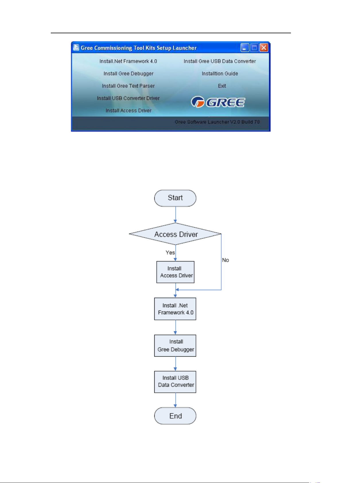
4.4.1.2 Installation flowchart
(1) Button Graphics
This flowchart describes basically the software installation process. See below for details.
26
DC Inverter Side Discharge VRF Ⅱ for North America
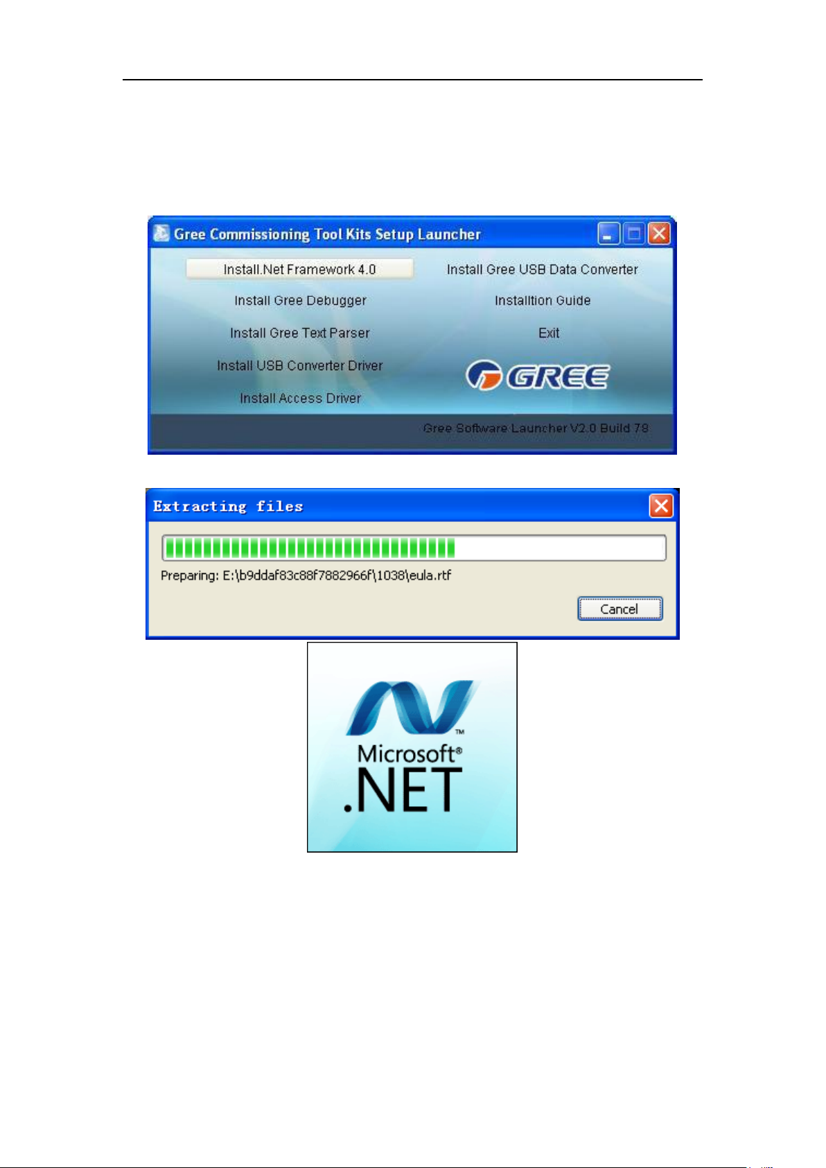
4.4.1.3 Installation process
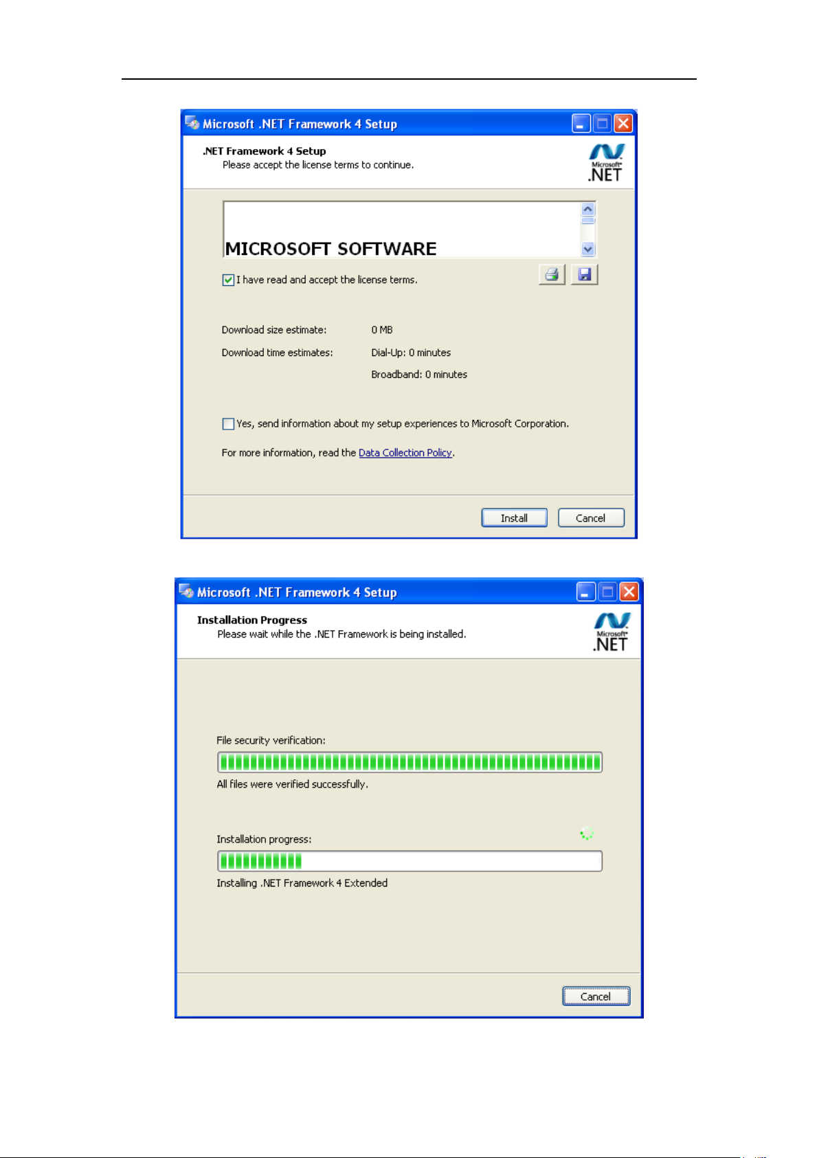
(1) Install .Net Framework 4.0
If your computer has installed .Net Framework 4.0 or versions above, there’s no need
to install again. Otherwise, click “Install .Net Framework 4.0”.
Extracting files
Click and select “I have read and accept the license terms”. Then click “Install”.
27
DC Inverter Side Discharge VRF Ⅱ for North America
Installation is in progress.
28
 Loading...