

Gree GMV-72WM/B-FU, GMV-144WM/B-F, GMV-120WM/B-F, GMV-120WM/B-FU, GMV-72WM/B-F Service Manual
...
GMV5 DC Inverter VRF Units SERVICE
MANUAL (For North America)
T1/R410A/60Hz
(GC201601-Π)

Contents
PREFACE ............................................................................................................................ 1
SAFTY PRECAUTIONS ...................................................................................................... 2
CHAPTER 1 INTRODUCTION TO BASIC FEATURES OF UNITS .................................... 7
1 MODELS LIST .......................................................................................................................................................... 7
2 BASIC OPERATING PRINCIPLE .......................................................................................................................... 7
3 INTERNAL PIPING DESIGN OF THE UNITS ...................................................................................................... 8
3.1 Piping Diagram of GMV-72WM/B-F(U) and GMV-96WM/B-F(U) ........................................................... 8
3.2 Piping Diagram of GMV-120WM/B-F(U) ..................................................................................................... 9
3.3 Names and Main Functions of Components.......................................................................................... 10
4 BASIC PARAMETERS OF UNIT.......................................................................................................................... 12
5 ELECTRICAL PARAMETERS ............................................................................................................................. 15
6 OPTIONAL ACCESSORIES ................................................................................................................................. 18
7 BASIC REQUIREMENT FOR PIPE CONNECTION ......................................................................................... 18
8 PRECAUTIONS ON REFRIGERANT LEAKAGE ............................................................................................. 21
9 UNIT OPERATING TEMPERATURE................................................................................................................... 23
CHAPTER 2 INSTALLATION ........................................................................................... 25
1 ENGINEERING INSTALLATION PREPARATION ............................................................................................ 25
1.1 INSTALLATION SAFETY .............................................................................................................................. 25
1.2 IMPORTANCE OF INSTALLATION ENGINEERING ................................................................................ 25
1.3 COOPERATION BETWEEN DIFFERENT PROFESSIONS .................................................................... 26
1.4 ONSITE REVIEW OF DESIGN DRAWING ................................................................................................ 29
1.5 CONSTRUCTION ORGANIZATION PROCESS ....................................................................................... 30
2 MATERIAL SELECTION ....................................................................................................................................... 31
2.1 REQUIREMENT FOR SELECTING CONSTRUCTION MATERIALS ................................................... 31
2.2 REQUIREMENT FOR SELECTING MAJOR MATERIALS ..................................................................... 31
3 INSTALLATION SPACE REQUIREMENT .......................................................................................................... 32
3.1 PLACE SELECTION FOR INSTALLING ODU .......................................................................................... 33
3.2 ODU DIMENSIONS AND INSTALLATION HOLE SIZE ........................................................................... 33
3.3 INSTALLATION SPACE REQUIREMENT FOR ODU .............................................................................. 35
4 REQUIREMENTS ON FOUNDATION INSTALLATION.................................................................................... 43
4.1 ODU FOUNDATION ....................................................................................................................................... 43
4.2 ODU FIXING .................................................................................................................................................... 44
4.3 VIBRATION REDUCTION FOR ODU ......................................................................................................... 44
5 PIPING CONNECTION .......................................................................................................................................... 45
5.1 Schematic Diagram of Piping Connection ............................................................................................. 45
5.2 Schematic Diagram of Piping Sequence ................................................................................................ 46
5.3 Allowable pipe length and drop height among indoor and outdoor units ..................................... 47
5.4 Connection Pipe among Outdoor Modules ............................................................................................ 49
5.5 Fitting pipe between Outdoor Unit and the First Manifold ................................................................. 51
6 PIPE INSTALLATION AND INSULATION .......................................................................................................... 57
6.1 PIPE INSTALLATION FOR THE COOLING SYSTEM ............................................................................. 57
6.2 PIPE INSTALLATION FOR THE CONDENSATE WATER SYSTEM ..................................................... 65
6.3 INSULATION SYSTEM .................................................................................................................................. 70
7 ELECTRIC AND CONTROLLER INSTALLATION ............................................................................................ 72
7.1 PRECAUTIONS .............................................................................................................................................. 72
7.2 INSTALLATION OF THE POWER CABLE ................................................................................................ 74
7.3 INSTALLATION OF THE COMMUNICATION SYSTEM .......................................................................... 78
8 VACUUMIZATION AND DESICCATION FOR THE REFRIGERANT SYSTEM ............................................ 86
8.1 AIR-TIGHTNESS TEST ................................................................................................................................. 86
8.2 VACUUMIZATION AND DESICCATION FOR THE SYSTEM ................................................................. 87
9 REFRIGERANT PERFUSION .............................................................................................................................. 89

9.1 CALCULATION METHOD FOR PERFUSING REFRIGERANT .......................................................... 89
9.2 METHOD FOR PERFUSING REFRIGERANT .......................................................................................... 91
CHAPTER 3 COMMISSIONING OPERATION ................................................................. 95
1 SECURITY REQUIREMENTS .............................................................................................................................. 95
1.1PRECAUTIONS FOR CONSTRUCTION ..................................................................................................... 95
1.2 PRECAUTIONS FOR THE USE OF REFRIGERANTS ........................................................................... 95
1.3 FUNCTION SETTINGS OF ODUS .............................................................................................................. 95
2 COMMISSIONING PROCESS ........................................................................................................................... 121
2.1 NECESSITY OF VRF ENGINEERING COMMISSIONING .................................................................... 121
2.2 REQUIRED FILES AND TOOLS FOR ENGINEERING COMMISSIONING ....................................... 121
2.3 ENGINEERING COMMISSIONING PROCEDURES .............................................................................. 122
2.4 REFERENCES FOR PROPER UNIT OPERATION PARAMETERS ................................................... 147
CHAPTER 4 MAINTENANCE ......................................................................................... 150
1 FAILURE CODE TABLE ...................................................................................................................................... 150
1.1 System Failure Code Table ...................................................................................................................... 150
2 EXCEPTION AND TROUBLESHOOTING ....................................................................................................... 156
2.1 How to locate a faulty IDU promptly ...................................................................................................... 156
2.2 Exception Analyzing and Troubleshooting .......................................................................................... 157
3 KEY PARTS MAINTENANCE ............................................................................................................................ 198
3.1 CAUTIONS ON CONTROLLER AP1 REPLACEMENT ......................................................................... 198
3.2 COMPRESSOR REPLACEMENT AND CAUTIONS .............................................................................. 204
3.3 CAUTIONS ON COMPRESSOR DRIVE REPLACEMENT ................................................................... 229
3.4 ASSEMBLING AND DISASSEMBLING KEY PARTS OF ODUS ........................................................ 233
3.5 UNIT MAINTENANCE ................................................................................................................................. 245
4 APPENDIXES ....................................................................................................................................................... 246
4.1 MINUTES ABOUT A DEBUG SOLUTION CONFIRMATION MEETING ............................................. 246
4.2 VISUAL INSPECTION CHECKLIST OF THE DEBUG SYSTEM ......................................................... 246
4.3 DEBUG PARAMETER RECORD LIST ..................................................................................................... 247
4.4 COMMON PARAMETER LISTS ................................................................................................................ 248
4.5 EXPLODED VIEWS AND SPARE PART LIST ........................................................................................ 258
CHAPTER 5 REMOTE CONTROL.................................................................................. 267
1 ENGINEERING DEBUGGER ............................................................................................................................. 267
1.1 Overview ....................................................................................................................................................... 267
1.2 System Networking .................................................................................................................................... 268
1.3 Hardware ....................................................................................................................................................... 269
1.4 Software Setup ............................................................................................................................................ 272
1.5. Using Debugger ......................................................................................................................................... 284
1.6 Software Debug ........................................................................................................................................... 302
2 REMOTE CONTROL ........................................................................................................................................... 303
2.1 MODBUS GATEWAY REMOTE MONITORING SYSTE ........................................................................ 303
2.2 BACnet GATEWAY REMOTE MONITORING SYSTE ........................................................................... 370

GMV5 D.C INVERTER MULTI VRF SERVICE MANUAL
PREFACE
This manual specifies safe operation requirements for GMV5 series VRF units from perspectives of
engineering and installation, commissioning and maintenance, as well as basic principles and
implementation methods. Professional operators must abide by relevant national (local) safety
requirements and technical specifications set forth in this manual during operations; otherwise, the air
conditioning system may fail or be damaged, and personnel safety accident may also occur.
1
GMV5 D.C INVERTER MULTI VRF SERVICE MANUAL
This is the safety alert symbol. It is used to alert you to potential personal injury hazards.
Obey all safety messages that follow this symbol to avoid possibleinjury or death.
WARNING
This mark indicates procedures which, if improperly performed, might lead to the death or
serious injury of the user.
CAUTION
This mark indicates procedures which, if improperly performed, might possibly result in
personal harm to the user, or damage to property.
NOTICE is used to address practices not related to personal injury.
SAFTY PRECAUTIONS
To prevent injury to the user or other people and property damage, the following instructions must
be followed.
Incorrect operation due to ignoring instruction will cause harm or damage. The seriousness is
classified by the following indications.
■Installation
Have all electric work done by a licensed electrician according to "Electric Facility
Engineering
Standard" and "Interior Wire Regulations" and the instructions given in this manual and
always use a special circuit.
• If the power source capacity is inadequate or electric work is performed improperly, electric shock
or fire may result.
Ask the dealer or an authorized technician to install the air conditioner.
• Improper installation by the user may result in water leakage, electric shock, or fire.
Always ground the product.
• There is risk of fire or electric shock.
Always install a dedicated circuit and breaker.
• Improper wiring or installation may cause fire or electric shock.
For re-installation of the installed product, always contact a dealer or an Authorized Service
Center.
• There is risk of fire, electric shock, explosion, or injury.
Do not install, remove, or re-install the unit by yourself (customer).
• There is risk of fire, electric shock, explosion, or injury.
Do not store or use flammable gas or combustibles near the air conditioner.
• There is risk of fire or failure of product.
Use the correctly rated breaker or fuse.
• There is risk of fire or electric shock.
2

GMV5 D.C INVERTER MULTI VRF SERVICE MANUAL
Prepare for strong wind or earthquake and install the unit at the specified place.
• Improper installation may cause the unit to topple and result in injury.
Do not install the product on a defective installation stand.
• It may cause injury, accident, or damage to the product.
When installing and moving the air conditioner to another site, do not charge it with a
different refrigerant from the refrigerant specified on the unit.
• If a different refrigerant or air is mixed with the original refrigerant, the refrigerant cycle may
malfunction and the unit may be damaged.
Do not reconstruct to change the settings of the protection devices.
• If the pressure switch, thermal switch, or other protection device is shorted and operated forcibly,
or parts other than those specified by GREE are used, fire or explosion may result.
Ventilate before operating air conditioner when gas leaked out.
• It may cause explosion, fire, and burn.
Securely install the cover of control box and the panel.
• If the cover and panel are not installed securely, dust or water may enter the outdoor unit and fire
or electric shock may result.
If the air conditioner is installed in a small room, measures must be taken to prevent the
refrigerant concentration from exceeding the safety limit when the refrigerant leaks.
• Consult the dealer regarding the appropriate measures to prevent the safety limit from being
exceeded.Should the refrigerant leak and cause the safety limit to be exceeded, hazards due to
lack of oxygen in the room could result.
■Operation
Do not damage or use an unspecified power cord.
• There is risk of fire, electric shock, explosion, or injury.
Use a dedicated outlet for this appliance.
• There is risk of fire or electrical shock.
Be cautious that water could not enter the product.
• There is risk of fire, electric shock, or product damage.
Do not touch the power switch with wet hands.
• There is risk of fire, electric shock, explosion, or injury.
When the product is soaked (flooded or submerged), contact an Authorized Service
Center.
• There is risk of fire or electric shock.
Be cautious not to touch the sharp edges when installing.
• It may cause injury.
Take care to ensure that nobody could step on or fall onto the outdoor unit.
3

GMV5 D.C INVERTER MULTI VRF SERVICE MANUAL
• This could result in personal injury and product damage.
Do not open the inlet grille of the product uring operation. (Do not touch the electrostatic
filter, if the unit is so equipped.)
• There is risk of physical injury, electric shock, or product failure.
■Installation
Always check for gas (refrigerant) leakage after installation or repair of product.
• Low refrigerant levels may cause failure of product.
Do not install the product where the noise or hot air from the outdoor unit could damage
the neighborhoods.
• It may cause a problem for your neighbors.
Keep level even when installing the product.
• To avoid vibration or water leakage.
Do not install the unit where combustible gas may leak.
• If the gas leaks and accumulates around the unit, an explosion may result.
Use power cables of sufficient current carrying capacity and rating.
• Cables that are too small may leak, generate heat, and cause a fire.
Do not use the product for special purposes, such as preserving foods, works of art, etc. It is
a consumer air conditioner, not a precision refrigeration system.
• There is risk of damage or loss of property.
Keep the unit away from children. The heat exchanger is very sharp.
• It can cause the injury, such as cutting the finger. Also the damaged fin may result in degradation
of capacity.
When installing the unit in a hospital, communication station, or similar place, provide
sufficient protection against noise.
• The inverter equipment, private power generator, high-frequency medical equipment, or radio
communication equipment may cause the air conditioner to operate erroneously, or fail to operate.
On the other hand, the air conditioner may affect such equipment by creating noise that disturbs
medical treatment or image broadcasting.
Do not install the product where it is exposed to sea wind (salt spray) directly.
• It may cause corrosion on the product. Corrosion, particularly on the condenser and evaporator
fins, could cause product malfunction or inefficient operation.
4

GMV5 D.C INVERTER MULTI VRF SERVICE MANUAL
■Operation
Do not use the air conditioner in specialenvironments.
• Oil, steam, sulfuric smoke, etc. can significantly reduce the performance of the air conditioner or
damage its parts.
Do not block the inlet or outlet.
• It may cause failure of appliance or accident.
Make the connections securely so that the outside force of the cable may not be applied
to the terminals.
• Inadequate connection and fastening may generate heat and cause a fire.
Be sure the installation area does not deteriorate with age.
• If the base collapses, the air conditioner could fall with it, causing property damage, product failure,
or personal injury.
Install and insulate the drain hose to ensure that water is drained away properly based on
the installation manual.
• A bad connection may cause water leakage.
Safely dispose of the packing materials.
• Packing materials, such as nails and other metal or wooden parts, may cause stabs or other
injuries. • Tear apart and throw away plastic packaging bags so that children may not play with
them. If children play with a plastic bag which was not torn apart, they face the risk of suffocation.
Turn on the power at least 6 hours before starting operation.
• Starting operation immediately after turning on the main power switch can result in severe damage
to internal parts. Keep the power switch turned on during the operational season.
Be very careful about product transportation.
• Only one person should not carry the product if it weighs more than 44lbs (20kg).
• Some products use PP bands for packaging. Do not use any PP bands for a means of
transportation. It is dangerous.
• Do not touch the heat exchanger fins. Doing so may cut your fingers.
• When transporting the outdoor unit, suspending it at the specified positions on the unit base. Also
support the outdoor unit at four points so that it cannot slip sideways.
Do not touch any of the refrigerant piping during and after operation.
• It can cause a burn or frostbite.
Do not operate the air conditioner with the panels or guards removed.
• Rotating, hot, or high-voltage parts can cause injuries.
Do not directly turn off the main power switch after stopping operation.
• Wait at least 5 minutes before turning off the main power switch. Otherwise it may result in water
leakage or other problems.
Auto-addressing should be done in condition of connecting the power of all indoor and
5

GMV5 D.C INVERTER MULTI VRF SERVICE MANUAL
outdoor units. Auto-addressing should also be done in case of changing the indoor unit PCB.
Use a firm stool or ladder when cleaning or maintaining the air conditioner.
• Be careful and avoid personal injury.
Do not insert hands or other objects through the air inlet or outlet while the air conditioner is
plugged in.
• There are sharp and moving parts that could cause personal injury.
6
GMV5 D.C INVERTER MULTI VRF SERVICE MANUAL
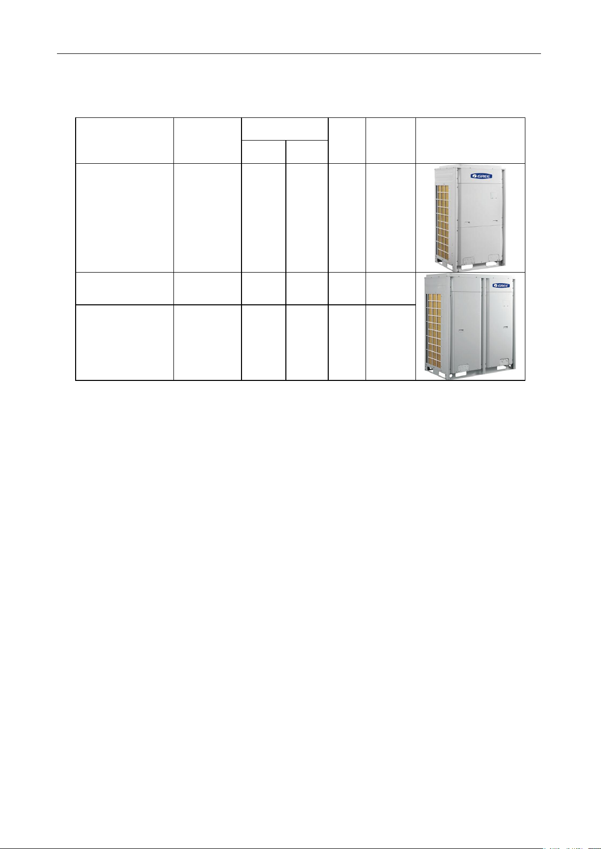
Model
Product Code
Capacity
Ref.
Power
Supply
Appearance
Cooling
(Btu/h)
Heating
(Btu/h)
GMV-72WM/B-F(U)
CN851W1380
CN851W1381
72000
81000
R410a
208/230V
3~60Hz
GMV-96WM/B-F(U)
CN851W1390
CN851W1391
96000
108000
R410a
208/230V
3~60Hz
GMV-120WM/B-F(U)
CN851W1420
CN851W1421
120000
135000
R410a
208/230V
3~60Hz
CHAPTER 1 INTRODUCTION TO BASIC FEATURES OF UNITS
1 MODELS LIST
2 BASIC OPERATING PRINCIPLE
Outdoor units of GMV5 VRF air conditioner can be implemented by combining multiple modules in
parallel. Similarly, indoor units (IDUs) consist of multiple units connecting in parallel. The operating
principle is as follows: When an IDU is operating in cooling mode, the outdoor unit (ODU) can
correspondingly enable the outdoor module based on the operating load requirement of the IDU. The
outdoor heat exchanger serves as a system condenser, and the heat exchangers of cooling IDUs are
connected in parallel to serve as a system evaporator. The circulation of air supply and air return of the
IDU is performed to adjust the indoor temperature and humidity. When an IDU is operating in heating
mode, all four-way valves in the ODU module are switched into energized status. The outdoor heat
exchange serves as the system evaporator, and the heat exchanger of the IDU serves as the system
condenser. The circulation of air supply and air return of the IDU is performed to adjust the indoor
temperature and humidity.
7
GMV5 D.C INVERTER MULTI VRF SERVICE MANUAL
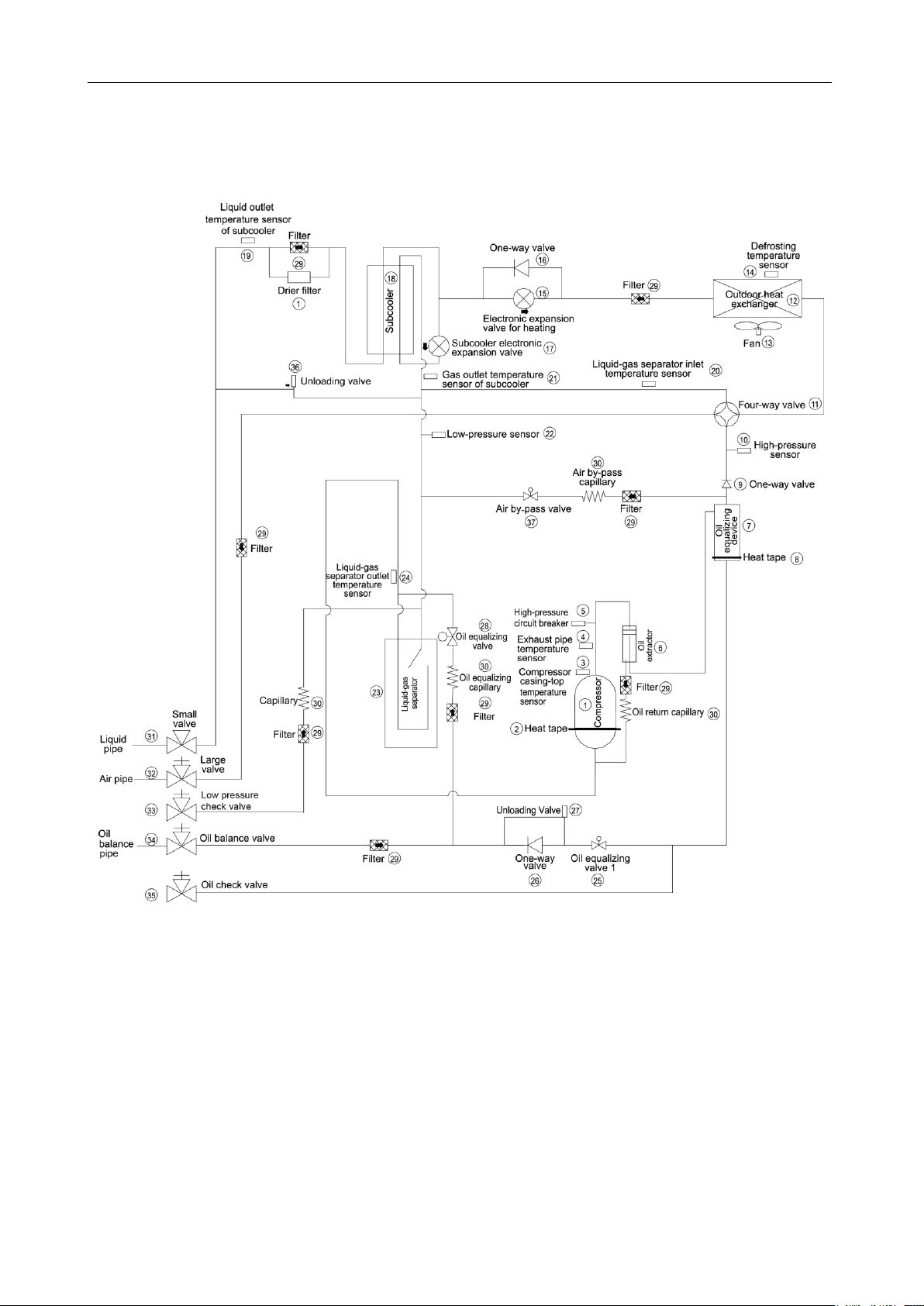
3 INTERNAL PIPING DESIGN OF THE UNITS
3.1 Piping Diagram of GMV-72WM/B-F(U) and GMV-96WM/B-F(U)
8
GMV5 D.C INVERTER MULTI VRF SERVICE MANUAL
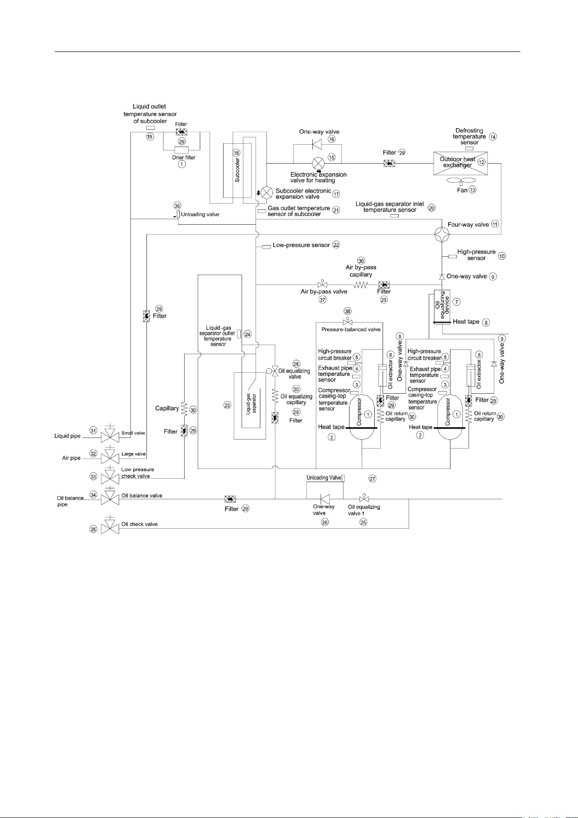
3.2 Piping Diagram of GMV-120WM/B-F(U)
9
GMV5 D.C INVERTER MULTI VRF SERVICE MANUAL
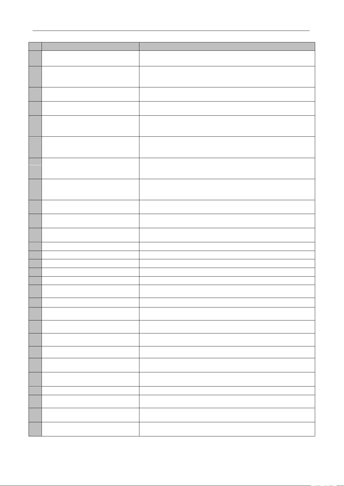
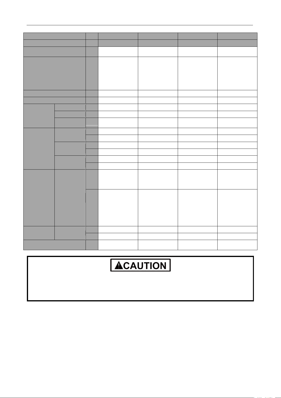
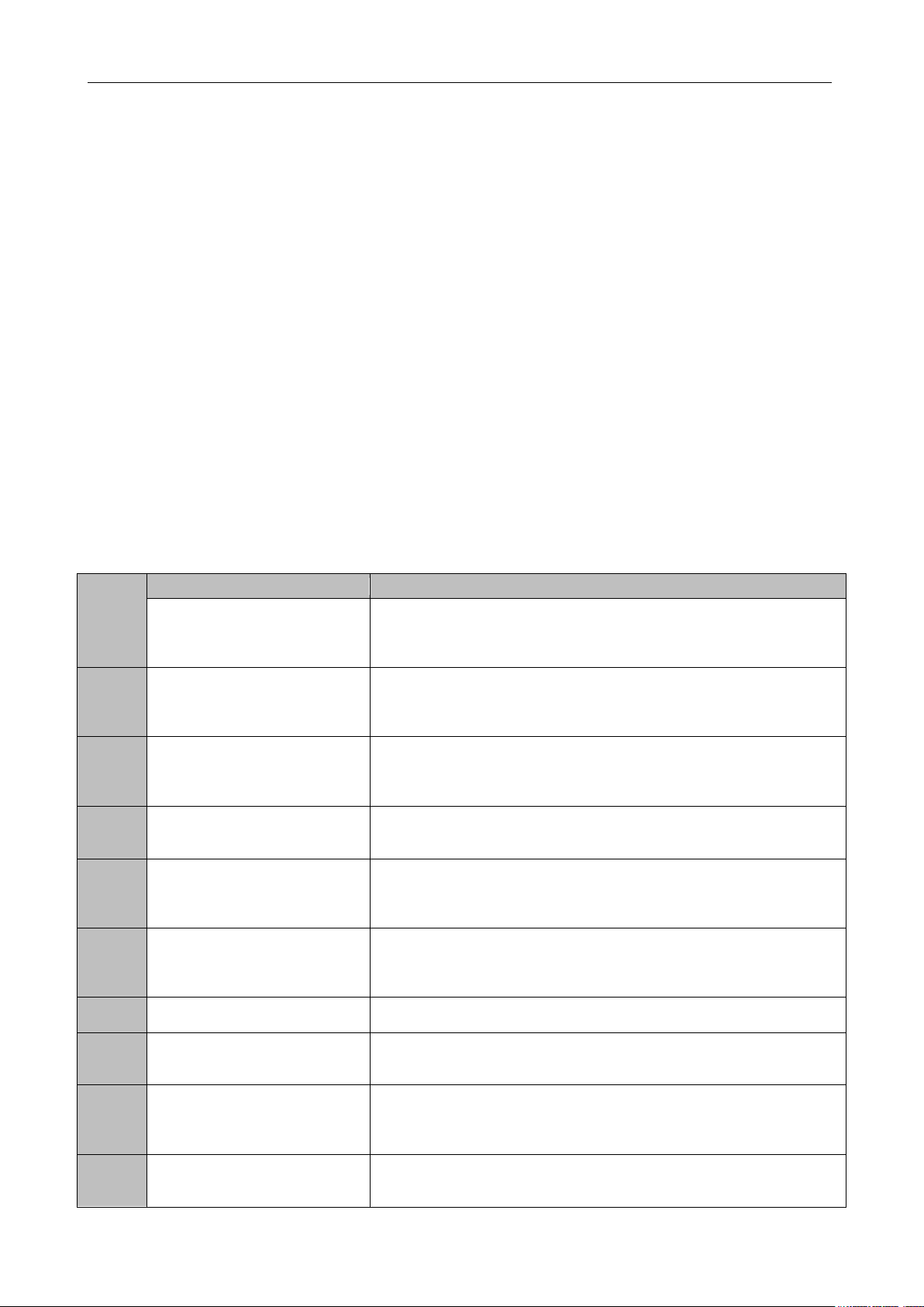
No
Name
Main Function
1
Compressor
Adjusts its own rotational speed based on the actual requirement of the
system to implement capacity control.
2
Compressor heat tape
Maintains a proper oil temperature in the compressor when the
compressor is in standby status, ensuring the reliability during
compressor startup.
3
Compressor casing-top temperature
sensor
Detects a compressor's exhaust gas temperature for compressor
control and protection.
4
Exhaust pipe temperature sensor of
compressor
Detects a compressor's exhaust gas temperature for compressor
control and protection.
5
High-pressure circuit breaker
Protects a compressor by sending feedback signal to stop the system
when the compressor's discharge temperature exceeds the operating
value of high-pressure circuit breaker.
6
Oil extractor
Separates the gas and oil in the system to ensure compressor
reliability.
7
Oil balance device
Equalizes the oil for all modules in the case of excess oil in the current
module when multiple modules are arranged in parallel, thus ensuring
the system reliability.
8
Heat tape of oil balance device
Maintains a proper oil temperature in the compressor when the
compressor is in standby status, ensuring the reliability of compressor
startup.
9
One-way valve
Prevents high-pressure gas from entering the compressor and fast
balances the suction pressure and discharge pressure in a compressor.
10
High-pressure sensor
Detects the high pressure value in the system in real time mode for
compressor protection and other control functions.
11
Four-way valve
Used for the switching between the cooling and heating functions of
system IDU.
12
Heat exchanger
Used for outdoor heat exchange.
13
Fan
Strengthens heat exchanging.
14
Defrosting temperature sensor
Used for defrosting detection.
15
Electronic expansion valve for heating
Controls refrigerant adjustment in heating mode.
16
One-way valve
Controls refrigerant flow direction.
17
Subcooler electronic expansion valve
Controls the degree of subcooling of tube refrigerant when the system
is running in cooling mode, and reduces the capacity loss on pipes.
18
Subcooler
Controls the degree of subcooling of tube.
19
Liquid outlet temperature sensor of
subcooler
Detects tube temperature.
20
Inlet temperature sensor of gas-liquid
separator
Detects the inlet temperature of gas-liquid separator to prevent the
system from running when the refrigerant flows back to the compressor.
21
Gas outlet temperature sensor of
subcooler
Detects gas temperature of subcooler.
22
Low-pressure sensor
Detects system low pressure to avoid extra-low operating pressure.
23
Gas-liquid separator
Separate gas and liquid to prevent the system from running when the
refrigerant flows back to the compressor.
24
Outlet temperature sensor of
gas-liquid separator
Detects internal status of gas-liquid separator to further control the
compressor suction performance.
25
Oil balance valve 1
Used for oil balance control among modules.
26
One-way valve
Used for oil balance control among modules and avoid reverse flow of
oil.
27
Unloading valve
Avoids over-high pressure caused by pipeline blind spot.
28
Oil balance valve 2
Used for oil balance control among modules.
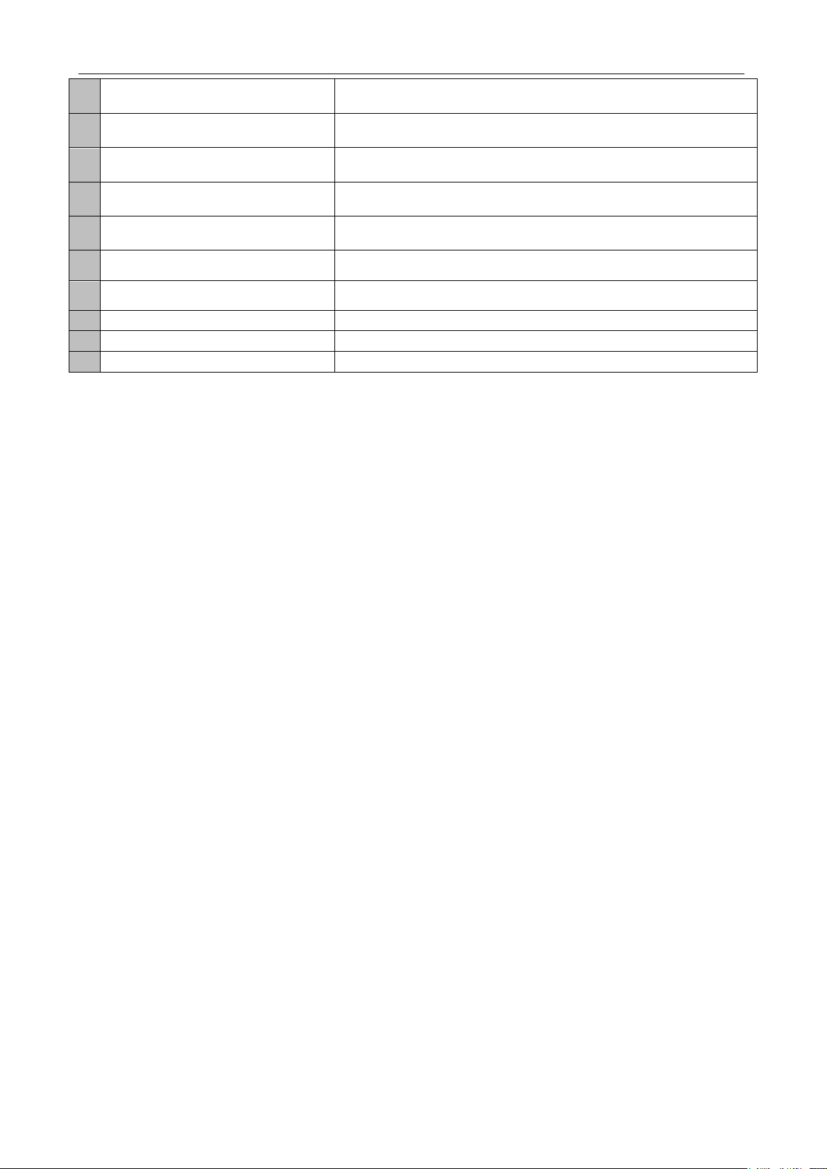
3.3 Names and Main Functions of Components
10
GMV5 D.C INVERTER MULTI VRF SERVICE MANUAL
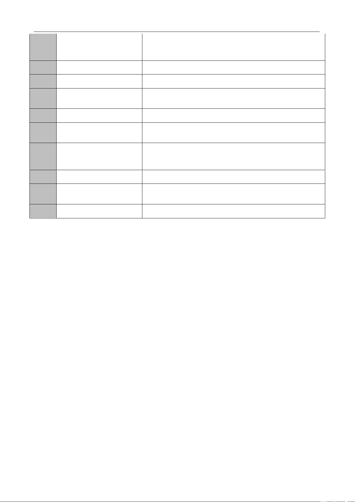
29
Filter
Prevents impurities from entering components and parts.
30
Capillary tube
Supports flow regulating and pressure reduction.
31
Liquid valve
Stop valve, closed when the unit is delivered from the factory and will
be opened after installation.
32
Gas valve
Stop valve, closed when the unit is delivered from the factory and will
be opened after installation.
33
Low-pressure measurement valve
Detects the low pressure value or charges refrigerant during system
running.
34
Oil balance valve
Stop valve, closed when the unit is delivered from the factory and will
be opened after installation.
35
Oil check valve
Checks the quality of refrigerating machine oil of compressor during
maintenance.
36
Unloading valve
Avoid over-high pressure caused by pipeline blind spot.
37
Air by-pass valve
Avoids extra-high or low operating pressure.
38
Pressure-balanced valve
Ensures success startup of compressor.
11
GMV5 D.C INVERTER MULTI VRF SERVICE MANUAL
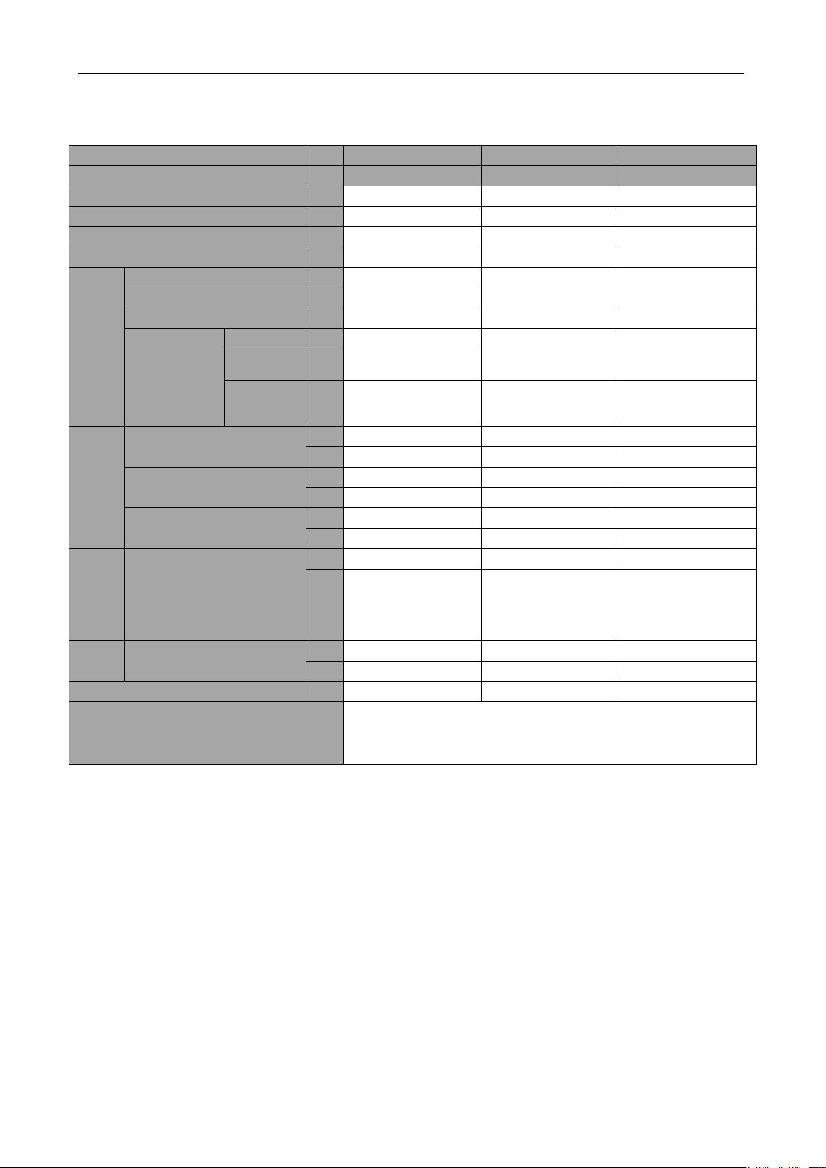
Outdoor Units_Heat Pump
-
6Ton
8Ton
10Ton
Horse Power
HP
8
10
12
Model
-
GMV-72WM/B-F(U)
GMV-96WM/B-F(U)
GMV-120WM/B-F(U)
Module combination
-
GMV-72WM/B-F(U)
GMV-96WM/B-F(U)
GMV-120WM/B-F(U)
Power Supply
-
208/230V 3~60Hz
208/230V 3~60Hz
208/230V 3~60Hz
Code
-
CN851W1380
CN851W1390
CN851W1420
Compr
essor
Type
-
Inverter scroll type
Inverter scroll type
Inverter scroll type
Number
N
1 1 2
Refrigeration Oil Brand
-
FVC68D or FV-68H
FVC68D or FV-68H
FVC68D or FV-68H
Oil Charge①
Total L 4 4 5.5
Compresso
r
L
1 1 1×2
Oil
Banlance
Tank
L
3 3 3.5
Pipe
Conne
ction
Gas Pipe Size
mm
19.05
22.2
28.6
in.
3/4
7/8
1 1/8
Liquid Pipe Size
mm
9.52
9.52
12.7
in.
3/8
3/8
1/2
Oil Balance Pipe Size
mm
9.52
9.52
9.52
in.
3/8
3/8
3/8
Dimen
sions
(width
×depth
×heigh
t)
External Dimension
mm
930×765×1605
1340×765×1605
1340×765×1605
in.
36-3/5×30-1/8×63-1/
5
52-3/4×30-1/8×63-1/
5
52-3/4×30-1/8×63-1/
5
Weight
Net Weight
kg
225
300
360
lbs.
496
661
794
Maximum qty of connected indoor units
unit
12
16
20
Remark
Oil charge includes the total oil amount of outdoor units, residual
oil amount of compressor and oil balance tank. When replacing the
compressor or oil balance tank, only the corresponding required oil
amount shall be charged
4 BASIC PARAMETERS OF UNIT
12
GMV5 D.C INVERTER MULTI VRF SERVICE MANUAL
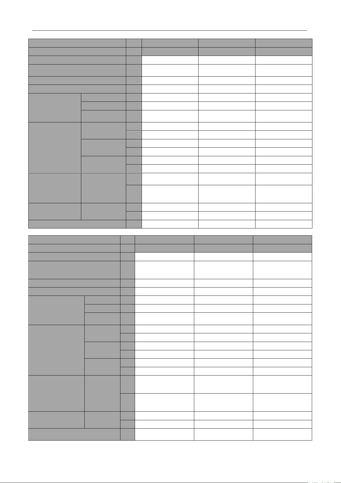
Outdoor Units_Heat Pump
-
12Ton
14Ton
16Ton
Horse Power
HP
14
18
20
Model
-
GMV-144WM/B-F(U)
GMV-168WM/B-F(U)
GMV-192WM/B-F(U)
Module combination
-
GMV-72WM/B-F(U)+
GMV-72WM/B-F(U)
GMV-72WM/B-F(U)+
GMV-96WM/B-F(U)
GMV-96WM/B-F(U)+
GMV-96WM/B-F(U)
Code
- - -
Power Supply
-
208/230V 3~60Hz
208/230V 3~60Hz
208/230V 3~60Hz
Compressor
Type
-
Inverter scroll type
Inverter scroll type
Inverter scroll type
Number N 1+1
1+1
1+1
Refrigeration Oil
Brand
-
FVC68D or FV-68H
FVC68D or FV-68H
FVC68D or FV-68H
Pipe Connection
Gas Pipe Size
mm
28.6
28.6
28.6
in.
1 1/8
1 1/8
1 1/8
Liquid Pipe Size
mm
12.7
15.9
15.9
in.
1/2
5/8
5/8
Oil Balance Pipe
Size
mm
9.52
9.52
9.52
in.
3/8
3/8
3/8
Dimensions
(width×depth×height
)
External
Dimension
mm
930×765×1605+
930×765×1605
930×765×1605+
1340×765×1605
1340×765×1605+
1340×765×1605
in.
36-3/5×30-1/8×63-1/5
+
36-3/5×30-1/8×63-1/5
36-3/5×30-1/8×63-1/5
+
52-3/4×30-1/8×63-1/5
52-3/4×30-1/8×63-1/5
+
52-3/4×30-1/8×63-1/5
Weight
Net Weight
kg
225+225
225+300
300+300
lbs.
496+496
496+661
661+661
Maximum qty of connected indoor units
unit
25
29
33
Outdoor Units_Heat Pump
-
18Ton
20Ton
22Ton
Horse Power
HP
22
24
26
Model
-
GMV-216WM/B-F(U)
GMV-240WM/B-F(U)
GMV-264WM/B-F(U)
Module combination
-
GMV-96WM/B-F(U)+
GMV-120WM/B-F(U)
GMV-120WM/B-F(U)+
GMV-120WM/B-F(U)
GMV-72WM/B-F(U)+
GMV-96WM/B-F(U)+
GMV-96WM/B-F(U)
Code
- - -
Power Supply
-
208/230V 3~60Hz
208/230V 3~60Hz
208/230V 3~60Hz
Compressor
Type
-
Inverter scroll type
Inverter scroll type
Inverter scroll type
Number N 1+2
2+2
1+1+1
Refrigeration
Oil Brand
-
FVC68D or FV-68H
FVC68D or FV-68H
FVC68D or FV-68H
Pipe Connection
Gas Pipe
Size
mm
28.6
34.9
34.9
in.
1 1/8
1 3/8
1 3/8
Liquid Pipe
Size
mm
15.9
15.9
19.05
in.
5/8
5/8
3/4
Oil Balance
Pipe Size
mm
9.52
9.52
9.52
in.
3/8
3/8
3/8
Dimensions
(width×depth×height)
External
Dimension
mm
1340×765×1605+
1340×765×1605
1340×765×1605+
1340×765×1605
930×765×1605+
1340×765×1605+
1340×765×1605
in.
52-3/4×30-1/8×63-1/5+
52-3/4×30-1/8×63-1/5
52-3/4×30-1/8×63-1/5+
52-3/4×30-1/8×63-1/5
36-3/5×30-1/8×63-1/5+
52-3/4×30-1/8×63-1/5+
52-3/4×30-1/8×63-1/5
Weight
Net Weight
kg
300+360
360+360
225+300+300
lbs.
661+749
749+749
496+661+661
Maximum qty of connected indoor
units
unit
37
41
45
13
GMV5 D.C INVERTER MULTI VRF SERVICE MANUAL
Outdoor Units_Heat Pump
-
24Ton
26Ton
28Ton
30Ton
Horse Power
HP
28
32
34
36
Model
-
GMV-288WM/B-F
(U)
GMV-312WM/B-F
(U)
GMV-336WM/B-F
(U)
GMV-360WM/B-F
(U)
Module combination
-
GMV-96WM/B-F(
U)+
GMV-96WM/B-F(
U)+
GMV-90WM/B-F(
U)
GMV-96WM/B-F(
U)+
GMV-96WM/B-F(
U)+
GMV-120WM/B-F
(U)
GMV-96WM/B-F(
U)+
GMV-120WM/B-F
(U)+
GMV-120WM/B-F
(U)
GMV-120WM/B-F
(U)+
GMV-120WM/B-F
(U)+
GMV-120WM/B-F
(U)
Code
- - -
Code
Power Supply
-
208/230V 3~60Hz
208/230V 3~60Hz
208/230V 3~60Hz
208/230V 3~60Hz
Compressor
Type
-
Inverter scroll type
Inverter scroll type
Inverter scroll type
Inverter scroll type
Number
N
1+1+1
1+1+2
1+2+2
2+2+2
Refrigeration
Oil Brand
-
FVC68D or
FV-68H
FVC68D or
FV-68H
FVC68D or
FV-68H
FVC68D or
FV-68H
Pipe
Connection
Gas Pipe
Size
mm
34.9
34.9
41.3
41.3
in.
1 3/8
1 3/8
1 5/8
1 5/8
Liquid Pipe
Size
mm
19.05
19.05
19.05
19.05
in.
3/4
3/4
3/4
3/4
Oil Balance
Pipe Size
mm
9.52
9.52
9.52
9.52
in.
3/8
3/8
3/8
3/8
Dimensions
(width×depth
×height)
External
Dimension
mm
1340×765×1605+
1340×765×1605+
1340×765×1605
1340×765×1605+
1340×765×1605+
1340×765×1605
1340×765×1605+
1340×765×1605+
1340×765×1605
1340×765×1605+
1340×765×1605+
1340×765×1605
in.
52-3/4×30-1/8×63
-1/5+
52-3/4×30-1/8×63
-1/5+
52-3/4×30-1/8×63
-1/5
52-3/4×30-1/8×63
-1/5+
52-3/4×30-1/8×63
-1/5+
52-3/4×30-1/8×63
-1/5
52-3/4×30-1/8×63
-1/5+
52-3/4×30-1/8×63
-1/5+
52-3/4×30-1/8×63
-1/5
52-3/4×30-1/8×63
-1/5+
52-3/4×30-1/8×63
-1/5+
52-3/4×30-1/8×63
-1/5
Weight
Net Weight
kg
225+300+360
225+360+360
300+360+360
360+360+360
lbs.
496+661+749
496+749+749
661+749+749
749+749+749
Maximum qty of connected
indoor units
unit
49
53
58
61
No matter how many outdoor units there are, the total rated capacity of indoor units must not
exceed 135% of the total rated capacity of outdoor units. Stable and safe operation can only be
guaranteed in a range of 50%~135%.
14

GMV5 D.C INVERTER MULTI VRF SERVICE MANUAL
Model
Power Supply
Fuse Capacity
Minimum Circuit
Ampacity
Maximum Overcurrent
Protection
V/Ph/Hz
A A A
GMV-72WM/B-F(U)
208V/230V 3~ 60Hz
45
30
45
GMV-96WM/B-F(U)
208V/230V 3~ 60Hz
70
45
70
GMV-120WM/B-F(U)
208V/230V 3~ 60Hz
100
74
100
GMV-144WM/B-F(U)
208V/230V 3~ 60Hz
70
55
70
GMV-168WM/B-F(U)
208V/230V 3~ 60Hz
90
70
90
GMV-192WM/B-F(U)
208V/230V 3~ 60Hz
125
99
125
GMV-216WM/B-F(U)
208V/230V 3~ 60Hz
125
111
125
GMV-240WM/B-F(U)
208V/230V 3~ 60Hz
150
140
150
GMV-264WM/B-F(U)
208V/230V 3~ 60Hz
150
123
150
GMV-288WM/B-F(U)
208V/230V 3~ 60Hz
150
136
150
GMV-312WM/B-F(U)
208V/230V 3~ 60Hz
175
164
175
GMV-336WM/B-F(U)
208V/230V 3~ 60Hz
200
177
200
GMV-360WM/B-F(U)
208V/230V 3~ 60Hz
225
205
225
Power cable wire gauge and circuit breaker must be selected based on the above parameters
and in compliance with local safety requirements. If there is conflict between above parameters and
national requirements, please contact the manufacture promptly.
If power cable wire gauge and circuit breaker is out of the above design range, fire hazard may
occur.
5 ELECTRICAL PARAMETERS
15
GMV5 D.C INVERTER MULTI VRF SERVICE MANUAL
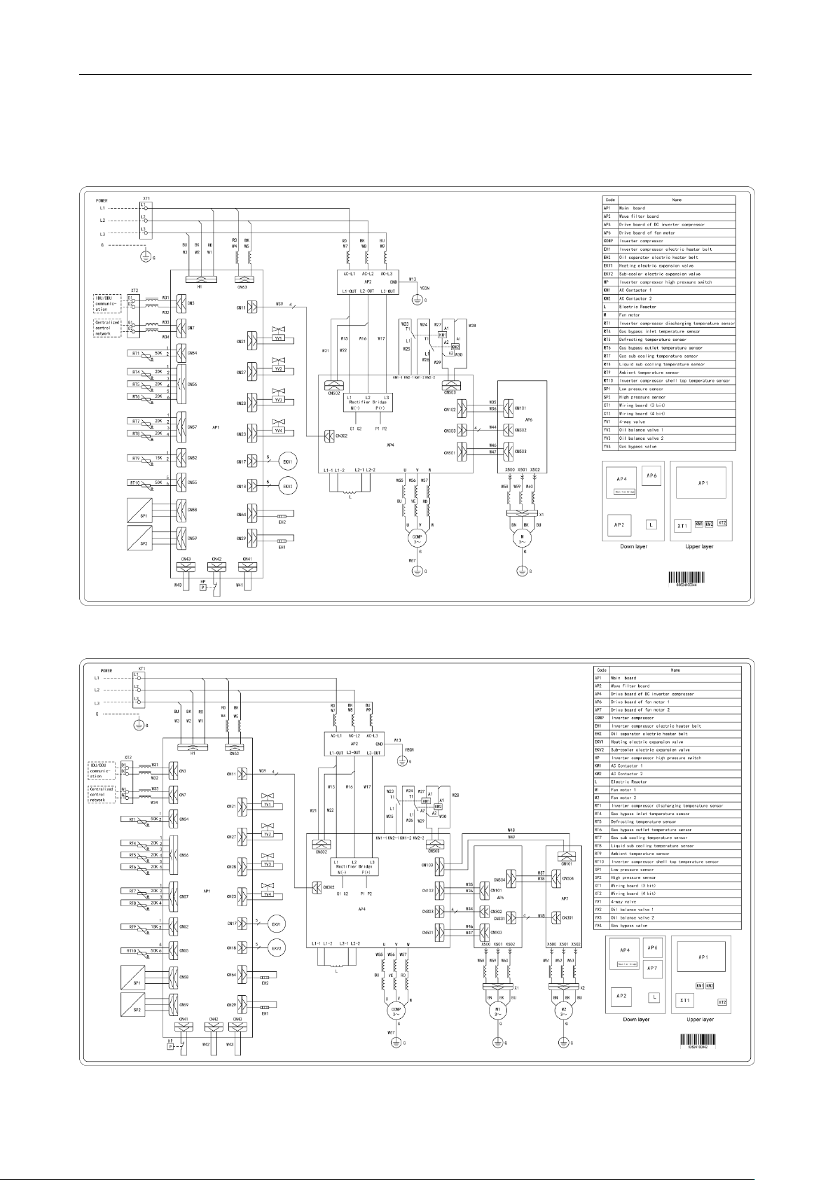
2. Circuit Diagram
2.1 Circuit Diagram of ODU
2.1.1 Circuit diagram of GMV-72WM/B-F(U)
2.1.2 Circuit diagram of GMV-96WM/B-F(U)
16
GMV5 D.C INVERTER MULTI VRF SERVICE MANUAL
When conducting maintenance based on above circuit diagrams, units must be power-off. Please
strictly following the circuit diagrams when reconnecting the wires, otherwise, electric shock may occur.
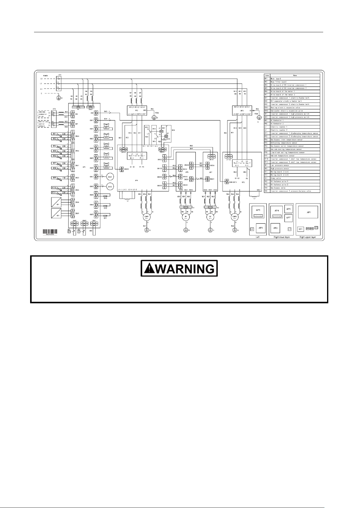
2.1.3Circuit diagram of GMV-120WM/B-F(U)
17
GMV5 D.C INVERTER MULTI VRF SERVICE MANUAL
Export Model
Remark
Manifold
ODU
ML01/A
For model selection, refer to Pipe Selection.
IDU
FQ01A/A, FQ01B/A, FQ02/A,
FQ03/A
Remote-control Receiver Board
JS03
Applicable for air-duct-type IDUs.
Commissioning Remote Controller
YV1L1
Provides the commissioning functions for
function settings of IDUs.
Commissioning Software
DE40-33/A(C)
Applicable for units that support CAN bus
communication technology.
Remote
Monitoring
System
Software
FE31-00/AD(BM)
Applicable for units that support CAN bus
communication technology.
Optoelectronic Isolation
Converter
GD02
Modbus Gateway
ME30-24/E4(M)
BACnet Gateway
MG30-24/D2(B)
6 OPTIONAL ACCESSORIES
GMV5 series VRF units support the following optional accessories:
NOTICE! Contact local sales company for optional accessories.
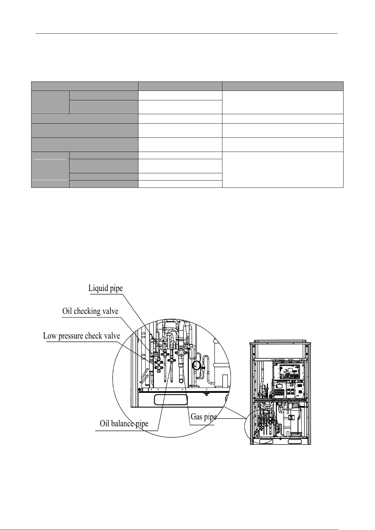
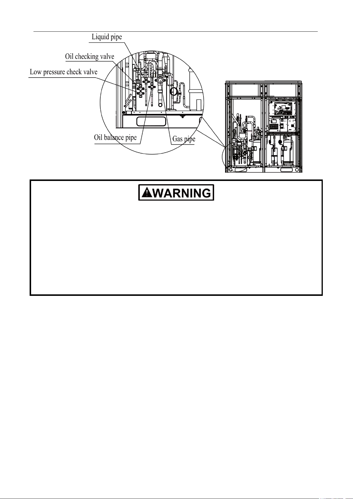
7 BASIC REQUIREMENT FOR PIPE CONNECTION
7.1 Outdoor units adopt the modular combination design of individual
cooling system, that is, units are connected by using pipes in parallel
during installation. The tubing system used among modules includes air
pipes, liquid pipes and oil balance pipes.
18
GMV5 D.C INVERTER MULTI VRF SERVICE MANUAL
Functions of oil check valve: During after-sale maintenance, the oil check valve can be used to
extract lubricating oil samples, which are further detected to analyze the oil quality in the system.
The oil check valve can also serve as the inlet for lubricating oil charging. Before extracting
lubricating oil from the system, stop the system for at least 12 hours and release refrigerant. Do not
extract oil until system‘s pressure drops to 0.05MPa (7.25psi) or below; otherwise, overheat oil may
burn the operator.
Functions of low-pressure check valve: It is mainly used for low pressure detection of the system
and refrigerant charging during after-sale maintenance.
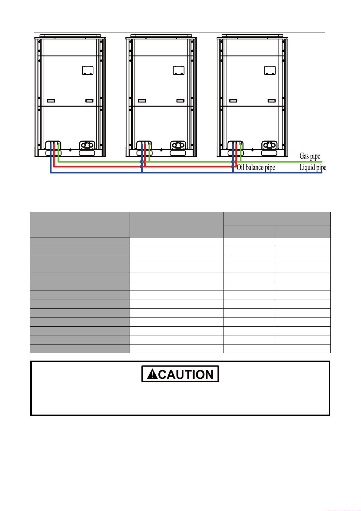
Pipe connection diagram of outdoor modules
19
GMV5 D.C INVERTER MULTI VRF SERVICE MANUAL
Model
Maximum Number of
Connected IDUs (units)
Capacity Range of Connected IDU
(kBtu/h)
Minimum Capacity
Maximum Capacity
GMV-72WM/B-F(U)
12
36.0
97.2
GMV-96WM/B-F(U)
16
48.0
129.6
GMV-120WM/B-F(U)
20
60.0
162.0
GMV-144WM/B-F(U)
25
72.0
194.4
GMV-168WM/B-F(U)
29
84.0
226.8
GMV-192WM/B-F(U)
33
96.0
259.2
GMV-216WM/B-F(U)
37
108.0
291.6
GMV-240WM/B-F(U)
41
120.0
324.0
GMV-264WM/B-F(U)
45
132.0
356.4
GMV-288WM/B-F(U)
49
144.0
388.8
GMV-312WM/B-F(U)
53
156.0
421.2
GMV-336WM/B-F(U)
58
168.0
453.6
GMV-360WM/B-F(U)
61
180.0
486.0
During installation, please strictly follow the above capacity range and number to construct,
otherwise, units may work abnormally and compressors may even be damaged
7.2 Each ODU system can be connected to multiple IDUs. Detailed information about the number of units to be connected and capacity ranges is shown in the following table:
20
GMV5 D.C INVERTER MULTI VRF SERVICE MANUAL
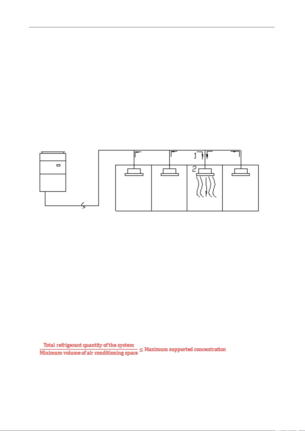
8 PRECAUTIONS ON REFRIGERANT LEAKAGE
Personnel related to air conditioning engineering design and installation operators must abide by
the safety requirement for preventing refrigerant leakage specified in local laws and regulations. If such
safety requirement is unavailable in local documents, the design and operation must be implemented
based on the following principles: GMV5 series VRF units adopt the R410A refrigerant, which is
nonflammable and nontoxic. However, the space for refrigerant leakage must be sufficient to ensure that
the refrigerant concentration does not exceed that specified in the safety requirement; otherwise, people
involved can be stifled by the refrigerant.
The maximum refrigerant charge and maximum refrigerant concentration in the system are
calculated directly based on the size of the air conditioning space. The unit of refrigerant concentration is
1 kg/m³ or 1lb/m³.
1) Flow direction of refrigerant leakage.
2) Room for refrigerant leakage. Since the concentration of refrigerant is greater than that of air, pay
attention to the spaces where the refrigerant may residue, for example, the basement.
Method for calculating the maximum concentration of refrigerant:
(1) Calculate the refrigerant charge quantity of each system.
Charge quantity of an ODU upon delivery (for the system consisting of multiple modules in parallel,
the accumulative charge quantity of modules upon delivery is used) + Onsite charge quantity = Total
refrigerant charge quantity in the system (kg)
(2) Calculate the volume of maximum air conditioning space (m³).
Volume of air conditioning space (m³) = Length x Width x Height
Note: The length, width and height here refer to the effective length, width and height of the indoor
space.
(3) Calculate the maximum refrigerant concentration of the refrigeration system.
Note: If the maximum supported refrigerant concentration is not available in relevant local standard,
use 0.3kg /m³ (0.66lbs/m³)as the maximum supported refrigerant concentration.
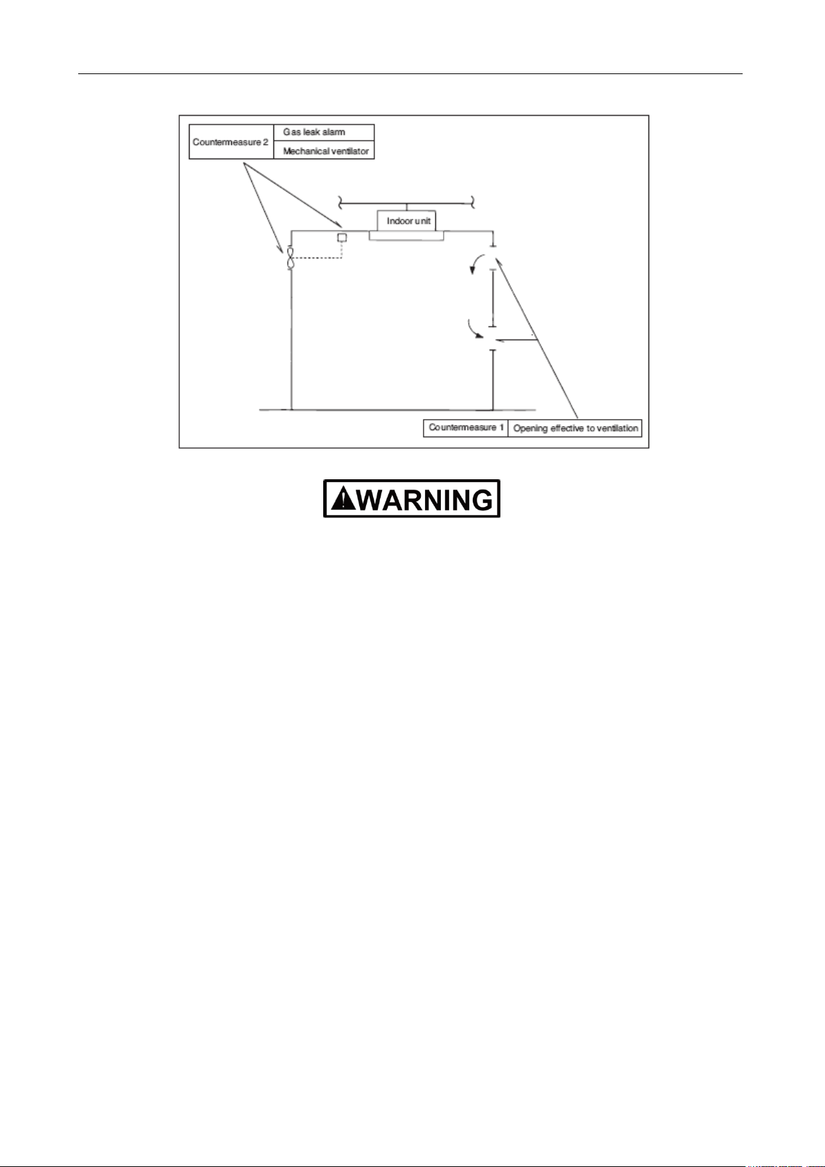
(4) If the maximum refrigerant concentration exceeds the allowed threshold, the refrigeration system
must be redesigned. In this case, separate the refrigeration system into multiple small-capacity
21
GMV5 D.C INVERTER MULTI VRF SERVICE MANUAL
refrigeration systems, or contact local Gree sales company.
If the above equation can not be satisfied, then follow the following steps.
Selection of air conditioning system: select one of the next
1). Installation of effective opening part
2). Reconfirmation of Outdoor Unit capacity and piping length
3). Reduction of the amount of refrigerant
4). Installation of 2 or more security device (alarm for gas leakage)
Change Indoor Unit type
: installation position should be over 6.6ft from the floor (Wall mounted type → Cassette type)
Adoption of ventilation system
: choose ordinary ventilation system or building ventilation system
Limitation in piping work
: Prepare for earthquake and thermal stress
22
GMV5 D.C INVERTER MULTI VRF SERVICE MANUAL
Cooling
Ambient temperature: -5ºC(23ºF)~52ºC(125.6ºF)
Heating
Ambient temperature: -20ºC (-4ºF)~24ºC (75.2ºF)
Cooling
Ambient temperature: 16ºC(60.8ºF)~45ºC(113ºF)
Heating
Ambient temperature: -7ºC (19.4ºF)~16ºC (60.8ºF)
If unit operates out of the above range, it may not work stably and components may even be
damaged.
9 UNIT OPERATING TEMPERATURE
In the case of a full fresh air conditioning IDU, the unit operating temperature is as follows:
23

GMV5 D.C INVERTER MULTI VRF SERVICE MANUAL
CHAPTER 2 INSTALLATION
24
GMV5 D.C INVERTER MULTI VRF SERVICE MANUAL
No.
Installation Problem
Possible Consequence
1
Dust or impurities enter into the
refrigeration system.
Pipes are more likely to be blocked; air conditioning performance is
reduced; compressor wear is increased
or even hinder the normal operation of the system and burn the
compressor.
2
Nitrogen is not filled into the
refrigerant pipe or insufficient
Nitrogen is filled before welding.
Pipes are more likely to be blocked; air conditioning performance is
reduced; compressor wear is increased
or even hinder the normal operation of the system and burn the
compressor.
3
The vacuum degree in the
refrigerant pipe is insufficient.
The refrigeration performance is reduced. The system fails to keep
normal operation due to frequent protection measures. When the problem
getting serious, compressor and other major components can be
damaged.
4
Water enters into the refrigeration
system.
Copper plating may appear on the compressor and reduce the
compressor efficiency with abnormal noise generated; failures may occur
in the system due to ice plug.
5
The refrigerant pipe specifications
do not meet the configuration
requirements.
Smaller configuration specifications can increase the system pipe
resistance and affect the cooling performance; larger configuration
specifications are waste of materials and can also reduce the cooling
performance.
6
Refrigerant pipe is blocked.
The cooling performance is reduced; in certain cases,
it may cause long-term compressor operating under overheat conditions;
the lubricating effect can be affected and the compressor may be burnt if
impurities were mixed with the lubricating oil.
7
Refrigerant pipe exceeds the limit.
The loss in pipe is considerable and the unit energy efficiency decreases,
which are harmful for long-term running of the system.
8
Incorrect amount of refrigerant is
filled.
The system cannot correctly control the flow allocation; the compressor
may be operating under over-heating environment or running when the
refrigerant flows back to the compressor..
9
The refrigerant pipe leaks.
Insufficient refrigerant circulating in the system decreases the cooling
performance of the air conditioner. Long-term operation under such
circumstance may cause an overheating compressor or even damage the
compressor.
10
Water drainage from the
condensate water pipe is not
smooth.
Residual water in IDUs can affect the normal operation of the system.
The possible water leakage can damage the IDU's decoration.
CHAPTER 2 INSTALLATION
1 ENGINEERING INSTALLATION PREPARATION
1.1 INSTALLATION SAFETY
Personnel and property safety are highly concerned during the entire installation process.
Installation implementation must abide by relevant national safety regulations to ensure personnel and
property safety.
All personnel involved in the installation must attend safety education courses and pass
corresponding safety examinations before installation. Only qualified personnel can attend the
installation. Relevant personnel must be held responsible for any violation of the regulation.
1.2 IMPORTANCE OF INSTALLATION ENGINEERING
VRF air conditioning systems use refrigerant, instead of other agent, to directly evaporate to carry
out the system heat. High level of pipe cleanness and dryness is required in the system. Since various
pipes need to be prepared and laid out onsite, carelessness or maloperation during installation may
leave impurities, water, or dust inside refrigerant pipes. If the design fails to meet the requirement,
various problems may occur in the system or even lead to system breakdown.
Problems that usually occur during installation are as follows:
25
GMV5 D.C INVERTER MULTI VRF SERVICE MANUAL
11
The ratio of slop for condensate
water pipe is insufficient or the
condensate water pipe is
incorrectly connected.
Reverse slop or inconsistent connection of condensate water pipe can
hinder the smooth drainage and cause leakage of the IDU.
12
The air channel is improperly
fixed.
The air channel will deform; vibration and noise occur during unit
operating.
13
The guide vane of air channel is
not reasonably manufactured.
Uneven air quantity allocation reduces the overall performance of the air
conditioner.
14
The refrigerant pipe or condensate
water pipe does not meet the
insulation requirement.
Water can easily condensate and drip to damage the indoor decoration,
or even trigger the protection mode of system due to overheating
operation.
15
The installation space for IDU is
insufficient.
Since there is a lack of space for maintenance and checking, indoor
decoration might need to be damaged during such operation.
16
The IDU or the location of the air
outlet or return air inlet is not
designed reasonably.
The air outlet or return air inlet may be short-circuited, thus affecting the
air conditioning performance.
17
The ODU is improperly installed.
The ODU is difficult to be maintained; unit exhaust is not smooth, which
reduces the heat exchanging performance or even prevent the system
from normal operation; in addition, the cold and hot air for heat exchange
and the noise may annoy people in surrounding areas.
18
Power cables are incorrectly
provided.
Unit components may be damaged and potential safety hazard may
occur.
19
Control communication cables are
incorrectly provided or improperly
connected.
The normal communication in the system fails or the control over IDUs
and ODUs turn in a mess.
20
Control communication cables are
not properly protected.
The communication cables are short-circuited or disconnected, and the
unit cannot be started up due to communication failure.
Understand the special requirement (if any) for unit installation before implementation to ensure
installation quality. Relevant installers must have corresponding engineering construction qualifications.
Special type operators involved in the engineering implementation, such as welders, electricians,
and refrigeration mechanics must have relevant operating licenses and are accredited with vocational
qualification certification.
1.3 COOPERATION BETWEEN DIFFERENT PROFESSIONS
A quality installation of air conditioning engineering depends on careful organization and close
cooperation between different professions such as architecture, structure, electric, water supply and
drainage, fire-fighting, and decoration. Pipes must be laid in places away from any automatic spray head
for fire-fighting, and must be reasonably arranged to ensure that the pipes fit the electric, luminaries, and
decoration.
1.3.1 Requirements for cooperation with civil engineering:
(1) The riser should be installed in the air conditioning tube well, and the horizontal pipe should be
placed in the ceiling, if possible.
(2) A place should be reserved for the ODU base to prevent the waterproof layer or insulating layer
on the roof from being damaged in later phase of installation.
(3) At places on walls or floors where pipes need to go through, holes or casing should be preserved.
If the pipe needs to go through a bearing beam, a steel casing must be prepared.
1.3.2 Requirements for cooperation with decoration engineering:
The air conditioning installation should not damage the bearing structure or the decorative style. Air
conditioning pipes should be laid out along the bottom of the beam as possible. If pipes meet one
another at the same elevation, process based on the following principles:
26

GMV5 D.C INVERTER MULTI VRF SERVICE MANUAL
(1) Drain pipes enjoy the highest priority. Air ducts and pressure pipes should leave places for
gravity pipes.
(2) Air ducts and small pipes should leave places for major pipes.
1.3.3 Requirements for cooperation with electric
After the capacity of air conditioning unit is determined, check the following aspects with relevant
electric design personnel:
(1) Whether the electrical load is designed based on the requirement of the air conditioning unit;
(2) Whether the power cable and circuit breaker meet the unit requirement and abide by relevant
national safety regulations;
(3) Whether the regional power supply quality (including voltage fluctuation and interference noise)
meet the international requirement;
(4) Any nonconformity must be resolved through coordination.
27
 Loading...