

Gree GMV-72WM/B-FU, GMV-144WM/B-F, GMV-120WM/B-F, GMV-120WM/B-FU, GMV-144WM/B-FU Owner's Manual
...
Owner's Manual
Original Instructions
Commercial Air Conditioners
GMV DC Inverter VRF
Models:
GMV-72WM/B-F (U)
GMV-96WM/B-F (U)
GMV-120WM/B-F (U)
GMV-144WM/B1-F (U)
……
GMV-360WM/B-F (U)
This is the safety alert symbol. It is used to alert you to potential personal injury
hazards. Obey all safety messages that follow this symbol to avoid possible
injury or death.
This mark indicates procedures which, if improperly performed, might lead to the death
or serious injury of the user.
This mark indicates procedures which, if improperly performed, might possibly result in
personal harm to the user, or damage to property.
NOTICE is used to address practices not related to personal injury.
(1) Instructions for installation and use of this product are provided by the manufacturer.
(2) Installation must be performed in accordance with the requirements of NEC and CEC by authorized personnel
only.
(3) For safety operation, please strictly follow the instructions in this manual.
(4) During operation, the gross rated capacity of working IDU should be within the gross rated capacity of ODU.
Otherwise, IDU’s cooling/heating performance will be reduced.
(5) This manual must be in the hands of direct operators or maintenance men.
(6) In case of malfunction and operation failure, please examine the following items and contact our authorized
service centers as soon as possible.
1) Nameplate (model, cooling capacity, product code, ex-factory date).
2) Malfunction status (detail description of conditions before and after malfunction occurs).
(7) All units have been strictly tested and proved to be qualified before ex-factory. To avoid unit damage or even
operation failure which may be caused by improper disassembly, please do not disassemble units by yourself.
If disassembly is needed, please contact our authorized serve centers for help.
(8) All graphics and information in this manual are only for reference. Manufacturer reserves the right for
changes in terms of sales or production at any time and without prior notice.
(9) If the supply cord is damaged, it must be replaced by the manufacturer, its service agent or similarly qualified
persons in order to avoid a hazard.
Preface
Gree DC Inverter Multi VRF System, with the most advanced technologies in the world, uses
eco-friendly refrigerant R410A as its cooling medium. For correct installation and operation, please
read this manual carefully.
his appliance can be used by children aged from 8 years and above and persons with
T
reduced physical, sensory or mental capabilities or lack of experience and knowledge if they have
been given supervision or instruction concerning use of the appliance in a safe way and
understand the hazards involved. Children shall not play with the appliance. Cleaning and user
maintenance shall not be made by children without supervision.
DISPOSAL: Do not dispose this product as unsorted municipal waste. Collection of
such waste separately for special treatment is necessary.

Contents
1 Safety Precautions ................................................................................................ 1
2 Product Introduction ............................................................................................. 2
2.1 Names of Main Parts ........................................................................................................... 2
2.2 Combinations of Outdoor Units ........................................................................................... 2
2.3 Combinations of Indoor and Outdoor Units .......................................................................... 3
2.4 The Range of Production Working Temperature.................................................................... 4
3 Preparation before Installation ............................................................................. 4
3.1 Standard Parts ..................................................................................................................... 4
3.2 Installation Site ................................................................................................................... 4
3.3 Piping Work Requirements .................................................................................................. 9
4 Installation Instruction .......................................................................................... 9
4.1 ODU Foundation ................................................................................................................. 9
4.2 Physical Dimension of the Outdoor Unit and Mounting Hole ............................................... 10
4.3 Connection Pipe ................................................................................................................ 13
4.4 Installation of the Connection Pipe .................................................................................... 23
4.5 Air Purging and Refrigerant Charge .................................................................................... 28
4.6 Electric Wiring ................................................................................................................... 31
4.7 System Communication ..................................................................................................... 33
4.8 Connection Method and Steps for System Communication ................................................. 38
4.9 External Electrical Wiring Diagram ..................................................................................... 43
5 Check Items after Installation and Trial Run ..................................................... 45
5.1 Check Items after Installation ............................................................................................ 45
5.2 Trial Run ........................................................................................................................... 45
6 Common Malfunction and Troubleshooting ...................................................... 58
7 Error Indication .................................................................................................... 60
8 Maintenance and Care......................................................................................... 64
8.1 Outdoor Heat Exchanger .................................................................................................... 64
8.2 Drain Pipe ......................................................................................................................... 64
8.3 Notice before Seasonal Use ............................................................................................... 65
8.4 Maintenance after Seasonal Use ........................................................................................ 65
8.5 Parts Replacement ............................................................................................................ 65
9 After-sales Service .............................................................................................. 65
(1) This product can’t be installed at corrosive, inflammable or explosive environment or the place with special
requirements, such as kitchen. Otherwise, it will affect the normal operation or shorten the service life of the
unit, or even cause fire hazard or serious injury. As for above special places, please adopt special air
conditioner with anti-corrosive or anti-explosion function.
(2) Follow this instruction to complete the installation work. Please carefully read this manual before unit startup
and service.
(3) Wire size of power cord should be large enough. The damaged power cord and connection wire should be
replaced by exclusive cable.
(4) After connecting the power cord, please fix the electric box cover properly in order to avoid accident.
(5) Never fail to comply with the nitrigen charge requirements. Charge nitrogen when welding pipes.
(6) Never short-circiut or cancel the pressure switch to prevent unit damage.
(7) Please firstly connect the wired controller before energization, otherwise wired controller cannot be used.
(8) Before using the unit, please check if the piping and wiring are correct to avoid water leakage, refrigerant
leakage, electric shock, or fire etc..
(9) Do not insert fingers or objects into air outlet/inlet grille.
(10) Open the door and window and keep good ventilation in the room to avoid oxygen deficit when the gas/oil
supplied heating equipment is used.
(11) Never start up or shut off the air conditioner by means of directly plug or unplug the power cord.
(12) Turn off the unit after it runs at least five minutes; otherwise it will influence oil return of the compressor.
(13) Do not allow children operate this unit.
(14) Do not operate this unit with wet hands.
(15) Turn off the unit or cut off the power supply before cleaning the unit, otherwise electric shock or injury may
happen.
(16) Never spray or flush water towards unit, otherwise malfunction or electric shock may happen.
(17) Do not expose the unit to the moist or corrosive circumstances.
(18) Under cooling mode, please don't set the room temperature too low and keep the temperature difference
between indoor and outdoor unit within 5℃(41℉).
(19) User is not allowed to repair the unit. Fault service may cause electric shock or fire accidents. Please contact
Gree appointed service center for help.
(20) Before installation, please check if the power supply is in accordance with the requirements specified on the
nameplate. And also take care of the power safety.
(21) Installation should be conducted by dealer or qualified personnel. Please do not attempt to install the unit by
yourself. Improper handling may result in water leakage, electric shock or fire disaster etc..
(22) Be sure to use the exclusive accessory and part to prevent the water leakage, electric shock and fire
accidents.
(23) Make sure the unit can be earthed properly and soundly after plugging into the socket so as to avoid electric
shock. Please do not connect the ground wire to gas pipe, water pipe, lightning rod or telephone line.
(24) Electrify the unit 8 hours before operation. Please switch on for 8 hours before operation. Do not cut off the
power when 24 hours short-time halting (to protect the compressor).
(25) If refrigerant leakage happens during installation, please ventilate immediately. Poisonous gas will emerge if
the refrigerant gas meets fire.
(26) Volatile liquid, such as diluent or gas will damage the unit appearance. Only use soft cloth with a little neutral
detergent to clean the outer casing of unit.
(27) If anything abnormal happens (such as burning smell), please power off the unit and cut off the main power
supply, and then immediately contact Gree appointed service center. If abnormality keeps going, the unit
might be damaged and lead to electric shock or fire.
1 Safety Precautions
GMV DC Inverter VRF
GREE will not assume responsibility of personal injury or equipment damage caused by
improper installation and commission, unnecessary service and incapable of following the rules
and instructions listed in this manual.
1
GMV DC Inverter VRF
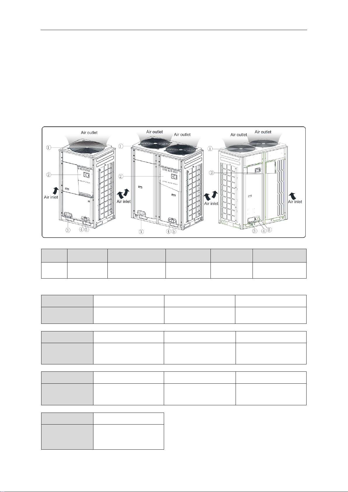
NO.
① ②
③
④ ⑤
Name
Fan, Motor
Electric Box Assembly
Valve interface
Power cord
through-hole
Communication code
through-hole
Model (Single)
GMV-144WM/B-F(U)
GMV-168WM/B-F(U)
GMV-192WM/B-F(U)
Model (Combined)
GMV-72WM/B-F(U)
+ GMV-72WM/B-F(U)
GMV-72WM/B-F(U)
+ GMV-96WM/B-F(U)
GMV-96WM/B-F(U)
+ GMV-96WM/B-F(U)
Model (Single)
GMV-216WM/B-F(U)
GMV-240WM/B-F(U)
GMV-264WM/B-F(U)
Model (Combined)
GMV-96WM/B-F(U)
+ GMV-120WM/B-F(U)
GMV-120WM/B-F(U)
+ GMV-120WM/B-F(U)
GMV-72WM/B-F(U)
+ GMV-96WM/B-F(U)
+ GMV-96WM/B-F(U)
Model (Single)
GMV-288WM/B-F(U)
GMV-312WM/B-F(U)
GMV-336WM/B-F(U)
Model (Combined)
GMV-96WM/B-F(U)
+ GMV-96WM/B-F(U)
+ GMV-96WM/B-F(U)
GMV-96WM/B-F(U)
+ GMV-96WM/B-F(U)
+ GMV-120WM/B-F(U)
GMV-96WM/B-F(U)
+ GMV-120WM/B-F(U)
+ GMV-120WM/B-F(U)
Model (Single)
GMV-360WM/B-F(U)
Model (Combined)
GMV-120WM/B-F(U)
+ GMV-120WM/B-F(U)
+ GMV-120WM/B-F(U)
2 Product Introduction
Gree Multi VRF Modular System adopts inverter compressor technology. According to change
the displacement of compressor, stepless capacity regulation within range of 10%-100% can be
realized. Various product lineup is provided with capacity range from 72kBtu/h to 360kBtu/h, which
can be widely used in working area and especially applicable to the place with variable load
change. Gree air conditioner is absolutely your best choice.
2.1 Names of Main Parts
2.2 Combinations of Outdoor Units
Fig.1
2
GMV DC Inverter VRF
ODU Model
Max number of
connectable IDU (unit)
ODU Model
Max number of
connectable IDU (unit)
GMV-72WM/B-F(U)
13
GMV-216WM/B-F(U)
36
GMV-96WM/B-F(U)
16
GMV-240WM/B-F(U)
39
GMV-120WM/B-F(U)
19
GMV-264WM/B-F(U)
46
GMV-144WM/B1-F(U)
23
GMV-288WM/B-F(U)
50
GMV-168WM/B1-F(U)
29
GMV-312WM/B-F(U)
53
GMV-144WM/B-F(U)
23
GMV-336WM/B-F(U)
56
GMV-168WM/B-F(U)
29
GMV-360WM/B-F(U)
59
GMV-192WM/B-F(U)
33
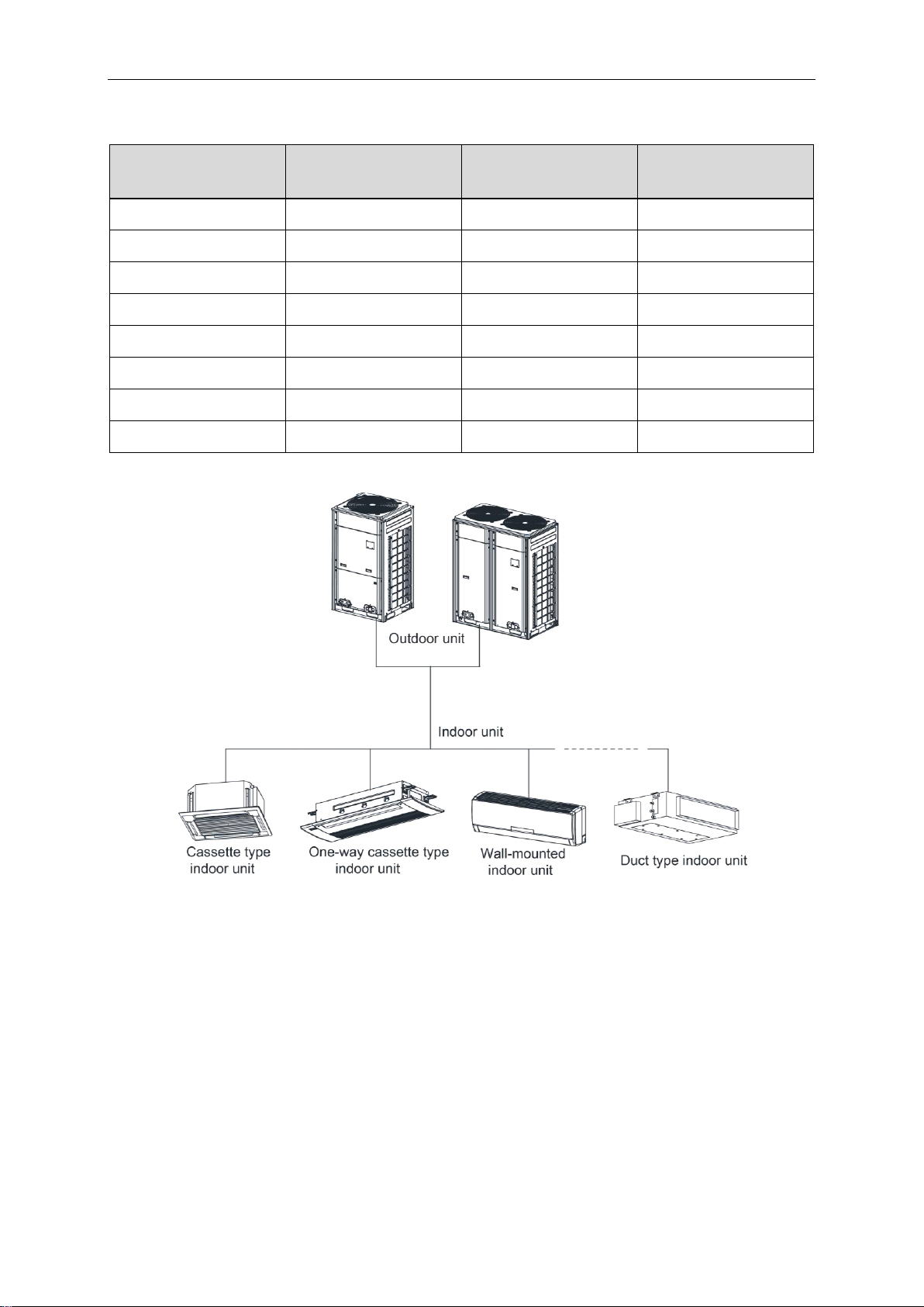
2.3 Combinations of Indoor and Outdoor Units
The total capacity of indoor units should be within 50%~135% of that of outdoor units.
Fig.2
Fig.2 is the combination view of the ODU of Modular DC Inverter Multi VRF System and the
IDU of Multi VRF System. IDU can be cassette type, one-way cassette type, wall-mounted type,
duct type, etc. When any one IDU receives operation signal, ODU will start to work according to
the capacity; when all IDUs stop, ODU will also stop.
3
GMV DC Inverter VRF
Cooling
Ambient temperature: -5℃(23℉)~52℃(125.6℉)
Heating
Ambient temperature: -20℃ (-4℉)~24℃ (75.2℉)
Cooling
Ambient temperature: 16°C(60.8℉)~45°C(113℉)
Heating
Ambient temperature: -7°C(19.4℉)~16°C(60.8℉)
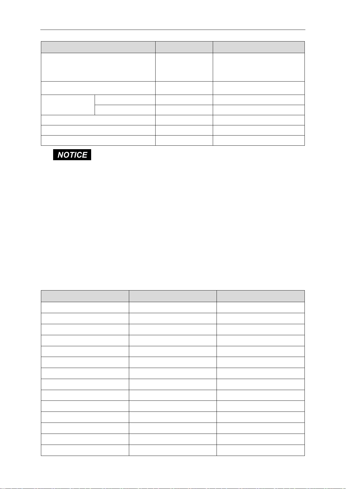
Parts for Outdoor Unit
Number
Name
Picture
Quantity
Remarks
1
Owner's Manual
1
2
Wiring (match with
resistance)
1
Must be connected to the last IDU
of communication connection
3
Mark (Master )
2
Attach on the wired controller of
master IDU or on the front panel
(1) Install the unit at a place where is adequate to withstand the weight of the unit and make sure the unit would
not shake or fall off.
(2) Never expose the unit under direct sunshine and rainfall. Install the unit at a place where is against dust,
typhoon and earthquake.
(3) Try to keep the unit away from combustible, inflammable and corrosive gas or exhaust gas.
(4) Leave some space for heat exchanging and servicing so as to guarantee unit normal operation.
(5) Keep the indoor and outdoor units close to each other as much as possible so as to decrease the pipe length
and bends.
(6) Never allow children to approach to the unit and take measures to prevent children touching the unit.
2.4 The Range of Production Working Temperature
When the indoor units are all VRF fresh air processor, the unit operating range is as follows:
NOTICE!
Out of the working Temperature Range may damage this product and will invalidate
the warranty.
3 Preparation before Installation
NOTICE!
(in.).
3.1 Standard Parts
Please use the following standard parts supplied by Gree.
The picture is only used for reference and the actual product prevails. Unit: mm
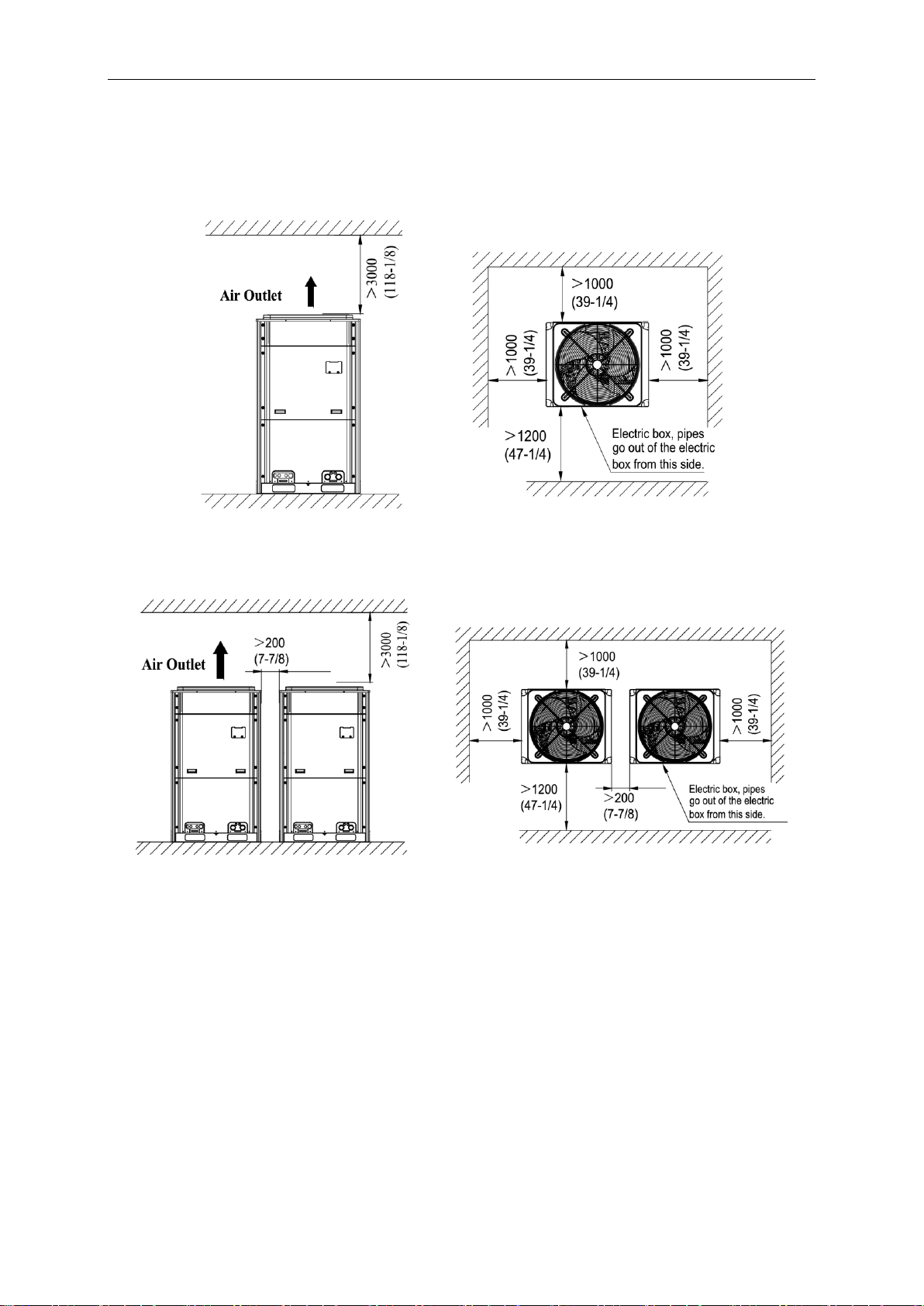
3.2 Installation Site
4
GMV DC Inverter VRF
3.2.1 When the outdoor unit is totally surrounded by walls, please refer to following figures for space dimension.
3.2.1.1 Space dimension for single-module unit
Unit: mm (in.)
Fig.3
3.2.1.2 Space dimension for dual-module unit
Fig.4
Unit: mm (in.)
5
GMV DC Inverter VRF
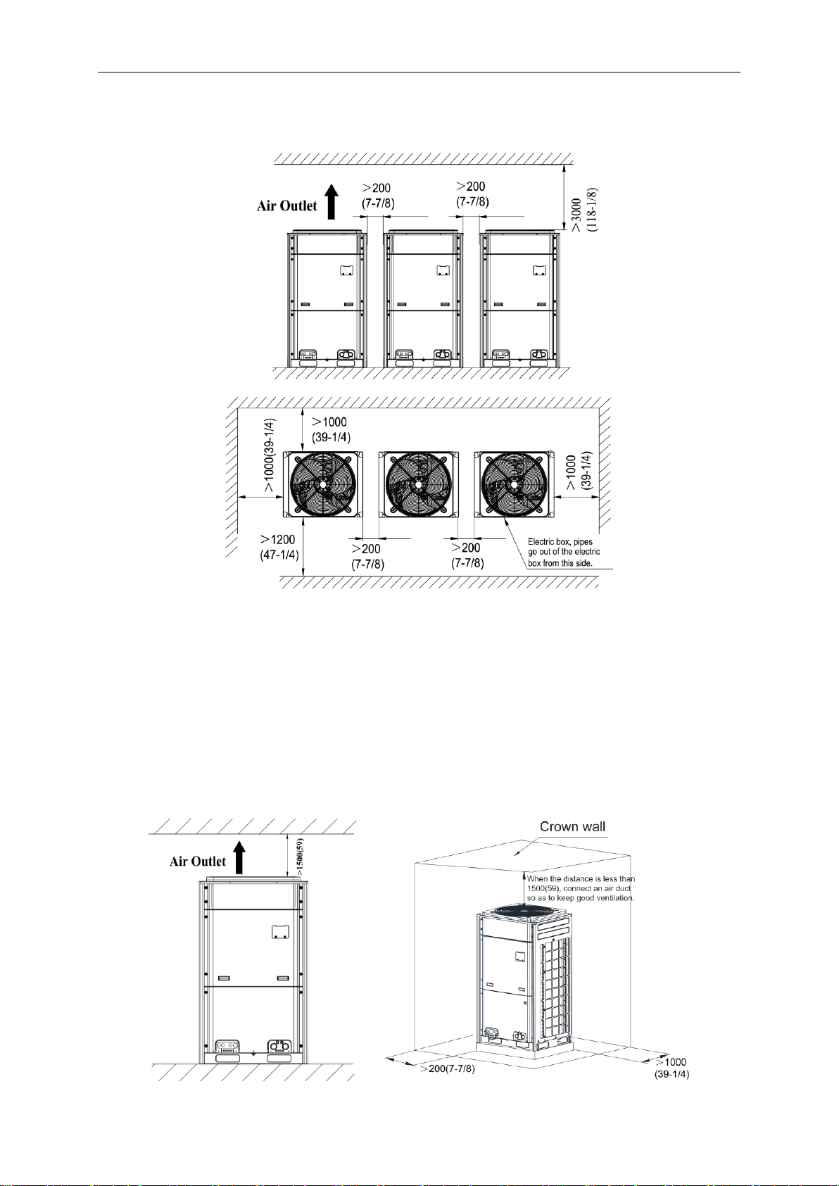
3.2.1.3 Space dimension for three-module unit
Unit: mm (in.)
Fig.5
3.2.2 Space dimension for outdoor unit top
When there is wall (or similar obstruction) above the unit, keep the distance between the unit
top and the wall at least 3000mm (118-1/8in.) or above. When the unit is located in a totally open
space with no obstructions in four directions, keep the distance between the unit top and wall at
least 1500mm (59in.) or above (See Fig.6). When space is limited within 1500mm (59in.) or the
unit is not set in an open space, air outlet pipe is required to be installed in order to keep good
ventilation (See Fig.7).
Unit: mm (in.)
Fig.6 Fig.7
6
GMV DC Inverter VRF
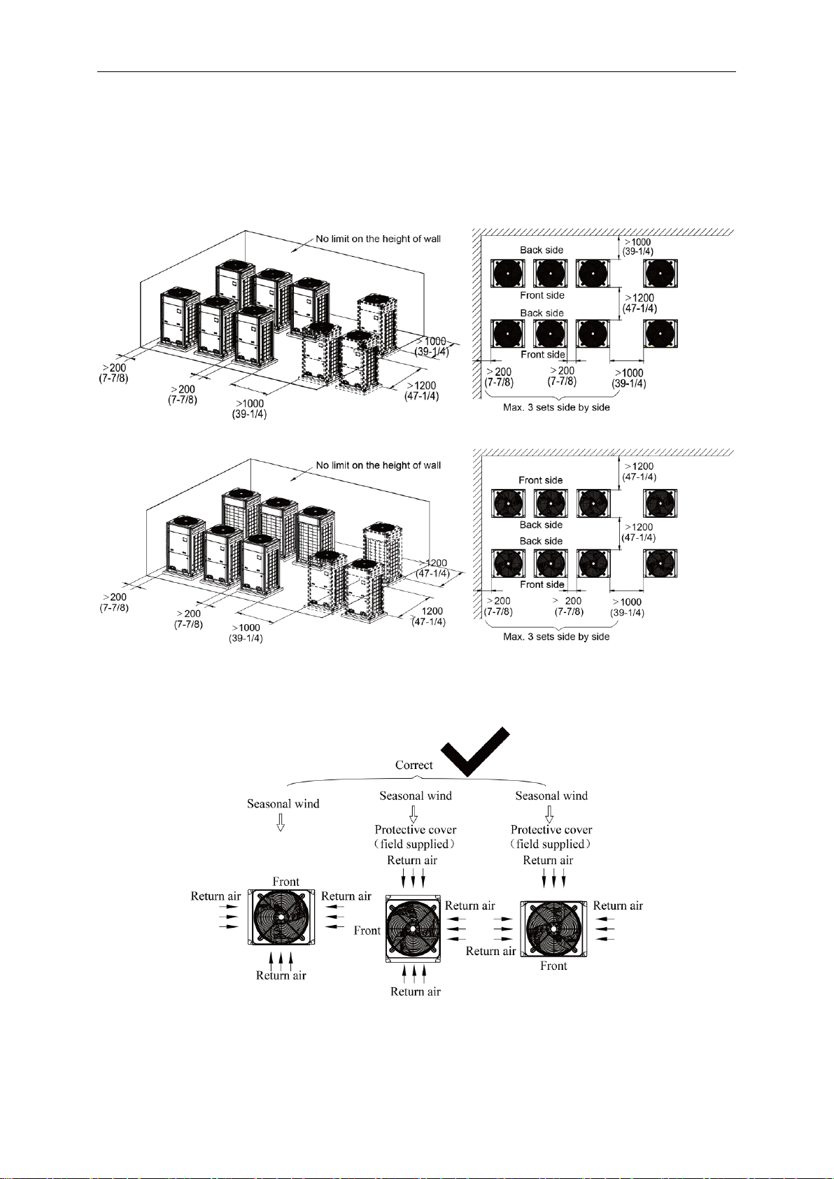
3.2.3 Space dimension for multiple-module unit
For keeping good ventilation, make sure there is no obstruction above the unit.
When the unit is located at a half-open space (front and left/right side is open), install the unit
as per the same or opposite direction.
Unit: mm (in.)
Fig.8
Fig.9
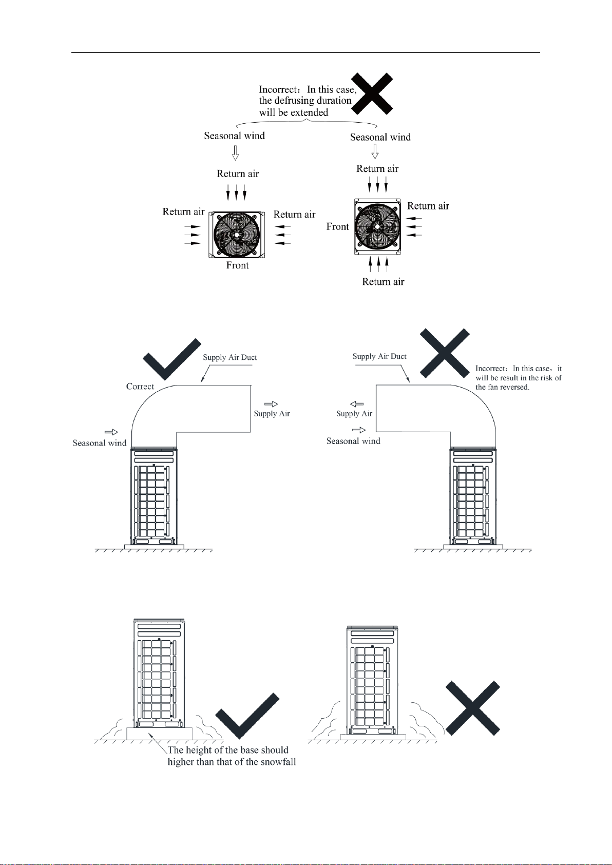
3.2.4 Considering the seasonal wind in outdoor unit installation
Anti-monsoon installation requirement for unit not connecting exhaust duct
Fig.10
7
GMV DC Inverter VRF
Fig.11
Anti-monsoon installation requirement for unit connecting exhaust duct
Fig.12
3.2.5 Considering snow in outdoor unit installation
Fig.13
8
GMV DC Inverter VRF
R410A Refrigerant System
Outer Diameter mm(in.)
Wall Thickness mm(in.)
Type
Φ6.35(1/4)
≥0.8(1/32)
O
Φ9.52(3/8)
≥0.8(1/32)
O
Φ12.7(1/2)
≥0.8(1/32)
O
Φ15.9(5/8)
≥1.0(3/76)
O
Φ19.05(3/4)
≥1.0(3/76)
1/2H
Φ22.2(7/8)
≥1.2(1/21)
1/2H
Φ28.6(1-1/8)
≥1.2(1/21)
1/2H
Φ34.9(1-3/8)
≥1.3(2/39)
1/2H
Φ41.3(1-5/8)
≥1.5(1/17)
1/2H
3.3 Piping Work Requirements
There should be no fall among outdoor modules. Refer to the table below for piping work
requirements.
4 Installation Instruction
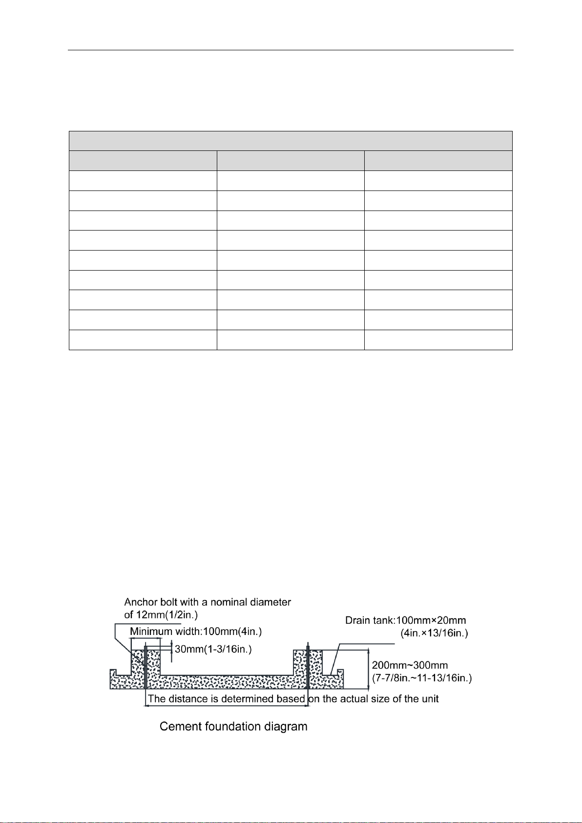
4.1 ODU Foundation
The concrete foundation of the ODU must be strong enough. Ensure that the drainage is
smooth and that the ground drainage or floor drainage is not affected.
Requirements on the concrete foundation are as follows:
A. The concrete foundation must be flat and have enough rigidity and strength to undertake
the unit’s weight during running. The height of the foundation is 200 mm(7-7/8 in.) to 300
mm(11-13/16 in.), which is determined based on the size of the unit.
B. Build a drainage ditch around the foundation to discharge the condensate water.
C. If the air conditioner is installed on the roof, check the intensity of the building and take
waterproof measures.
D. If a u-steel foundation is adopted, the structure must be designed with sufficient rigidity
and strength.
Fig. 14
9
GMV DC Inverter VRF
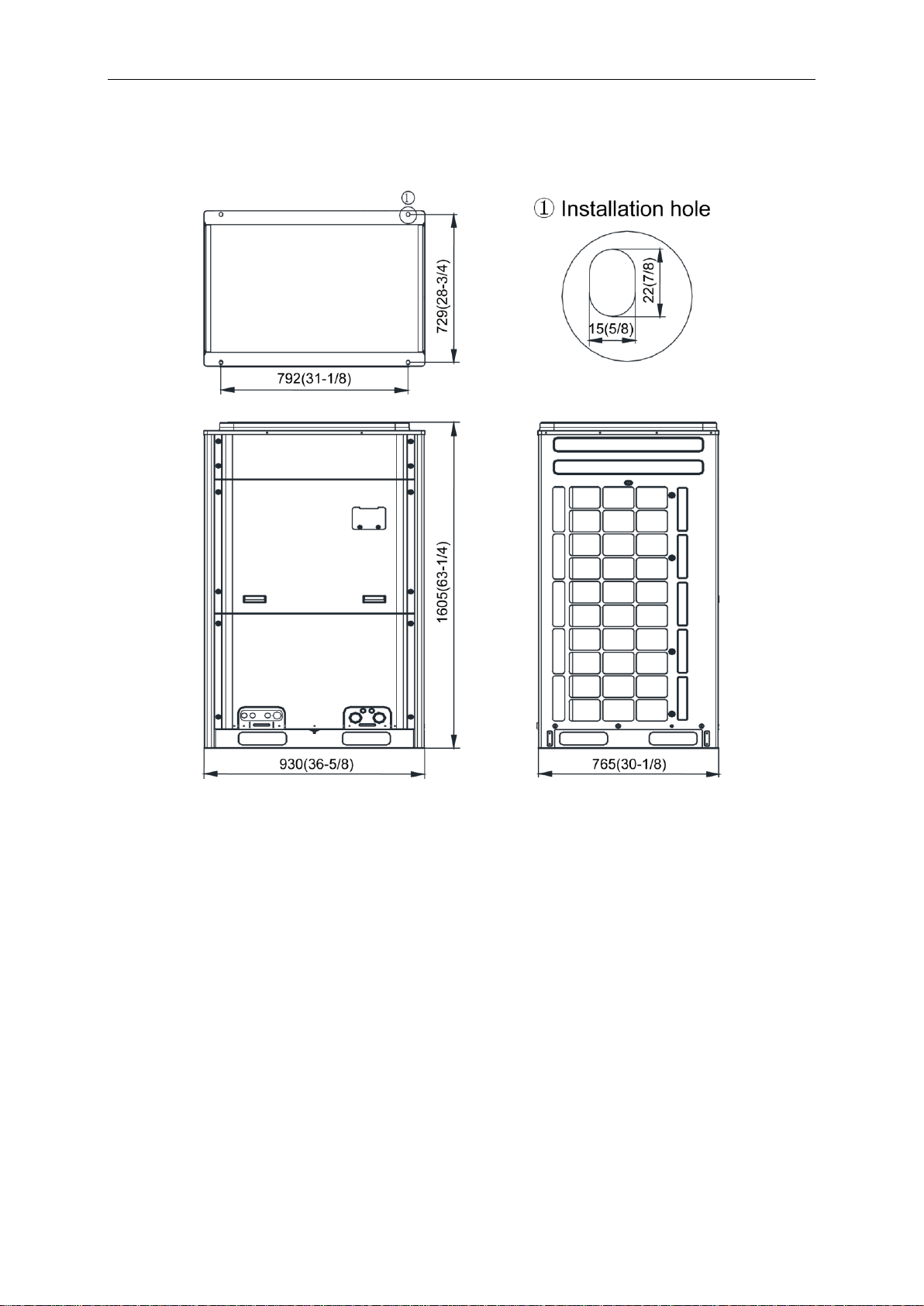
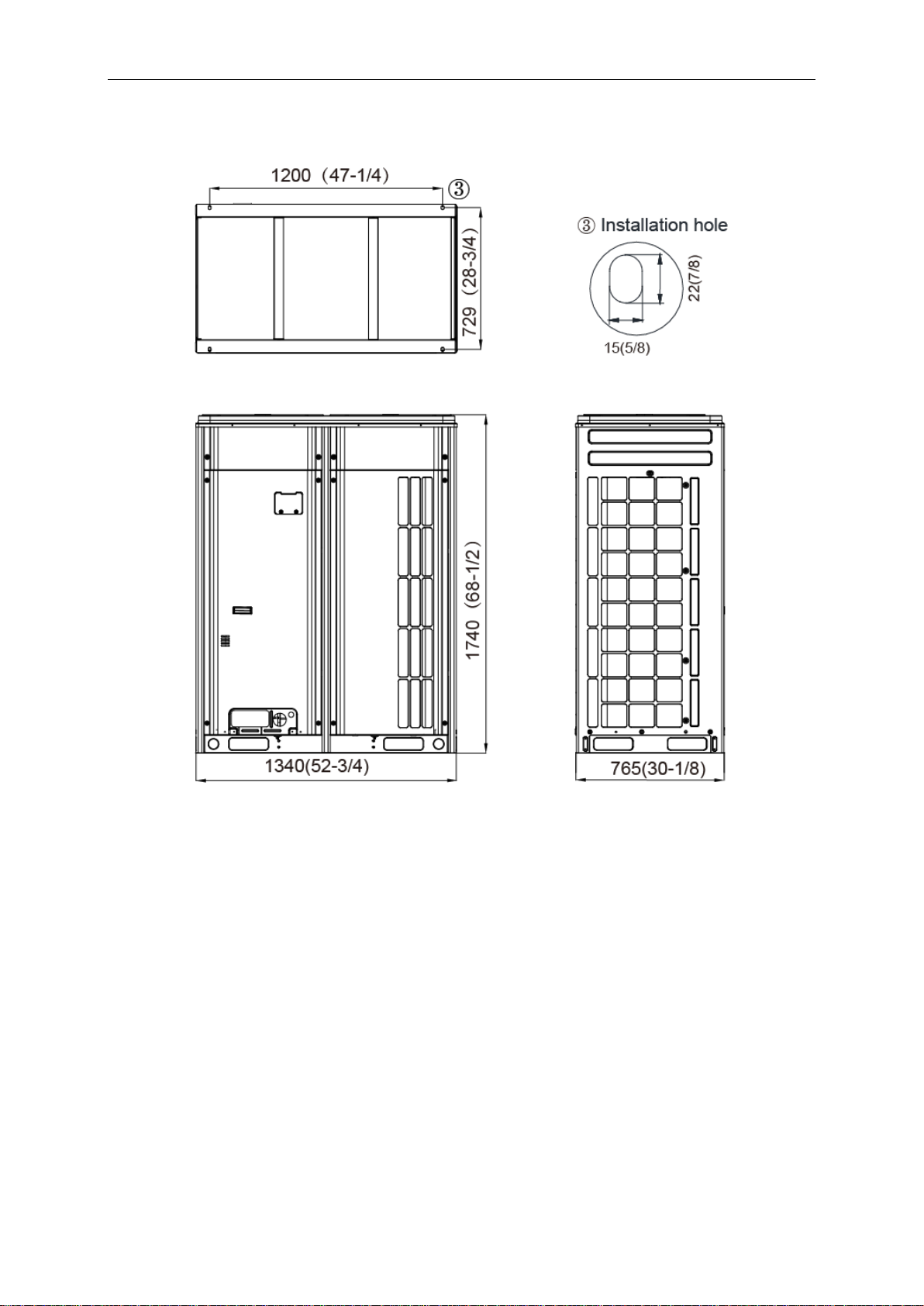
4.2 Physical Dimension of the Outdoor Unit and Mounting Hole
Outline and Physical Dimensions of GMV-72WM/B-F (U).
Unit: mm (in.)
Fig.15
10
GMV DC Inverter VRF
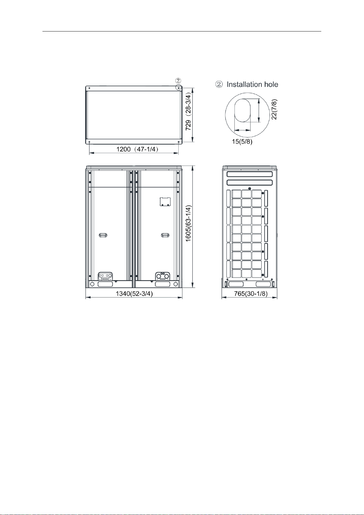
Outline and Physical Dimensions of GMV-96WM/B-F(U) 、GMV-120WM/B-F(U) and
GMV-144WM/B1-F(U).
Unit: mm (in.)
Fig.16
11
GMV DC Inverter VRF
Outline and Physical Dimensions of GMV-168WM/B1-F(U).
Unit: mm (in.)
Fig.17
12
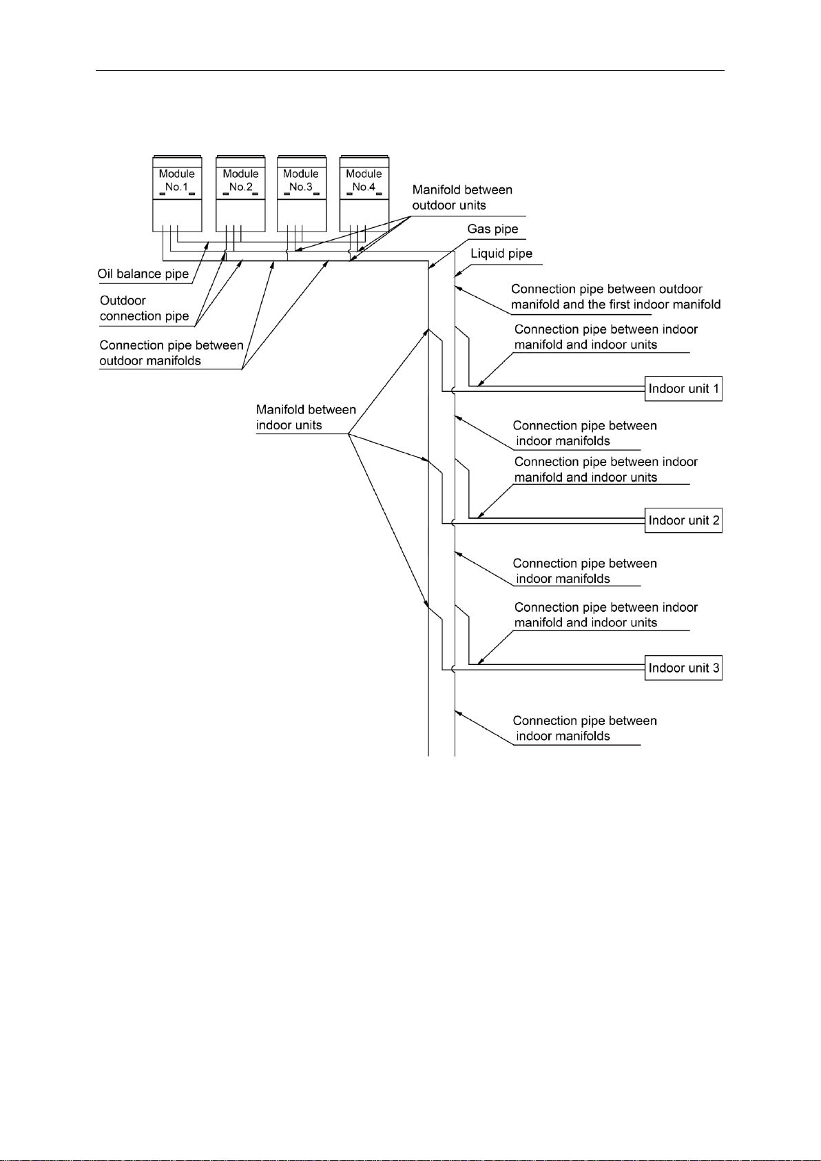
4.3 Connection Pipe
4.3.1 Schematic Diagram of Piping Connection
GMV DC Inverter VRF
Fig.18
13
GMV DC Inverter VRF
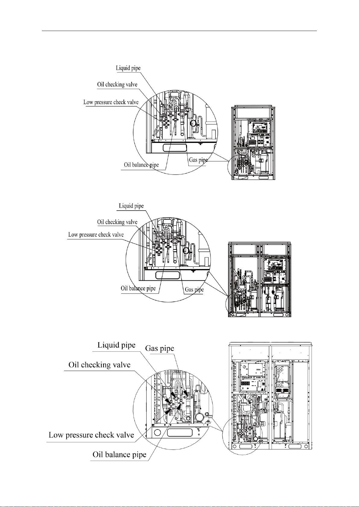
4.3.2 Schematic Diagram of Piping Sequence
GMV-72WM/B-F (U)
Fig.19
GMV-96WM/B-F(U) / GMV-120WM/B-F(U) and GMV-144WM/B1-F(U)
GMV-168WM/B1-F(U)
Fig.20
Fig.21
14
GMV DC Inverter VRF
R410A Refrigerant System
Allowable Value m(ft.)
Fitting Pipe
Total length (actual length) of fitting pipe
≤1000(3280-3/4)
L1+L2+L3+L4+…+L9+a+b+…+i+j
Length of farthest
fitting pipe m(ft.)
Actual length
≤165(541-1/4)
L1+L6+L7+L8+L9+j
Equivalent length
≤190(623-1/4)
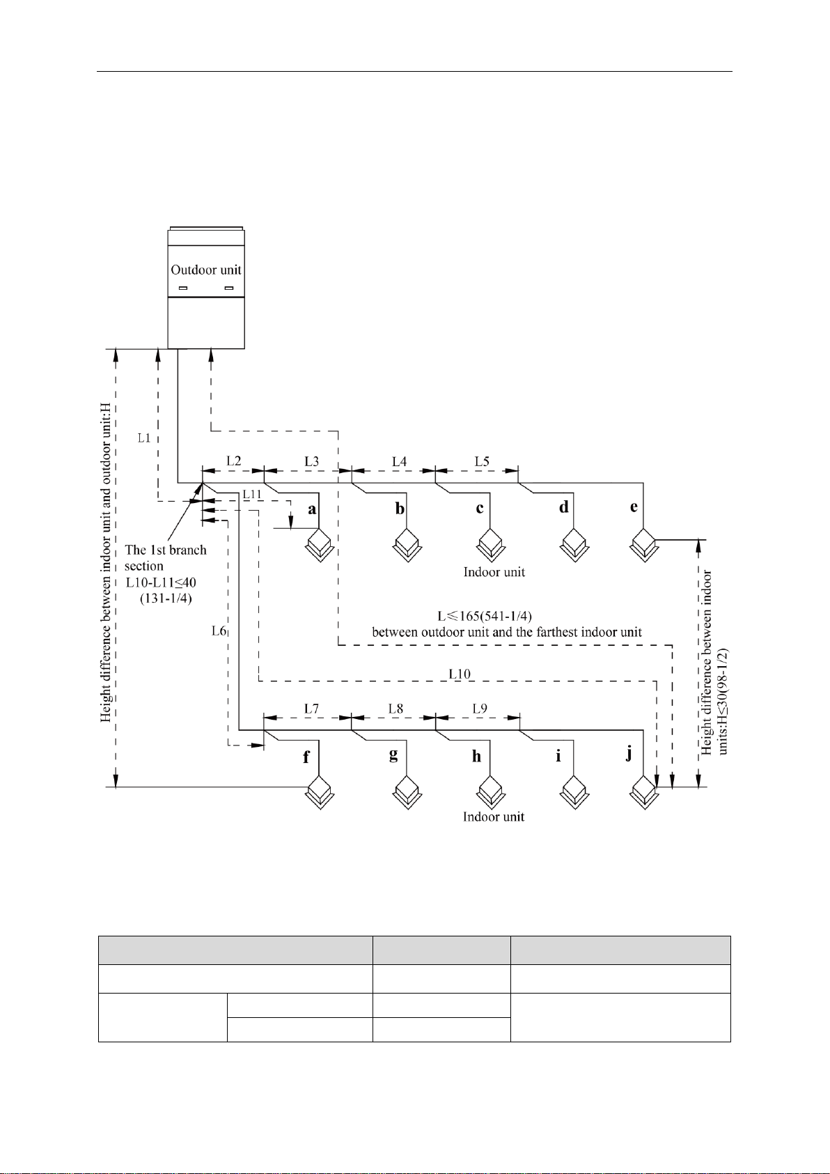
4.3.3 Allowable pipe length and drop height among indoor and outdoor units
Y type branch joint is adopted to connect indoor and outdoor units. Connecting method is
shown in the figure below.
Remark: Equivalent length of one Y-type manifold is about 0.5m (1-3/4ft.).
Unit: m (ft.)
Fig.22
L10: Length from the first branch to the farthest IDU;
L11: Length from the first branch to the nearest IDU;
Equivalent length of branch of IDU is 0.5m (1-3/4ft.).
.
15
GMV DC Inverter VRF
R410A Refrigerant System
Allowable Value m(ft.)
Fitting Pipe
Difference between the pipe length from the
first branch of IDU to the farthest IDU and the
pipe length from the first branch of IDU to the
nearest IDU
≤40(131-1/4)
L10-L11
Equivalent length from the first branch to the
furthest piping (1)
≤40(131-1/4)
L6+L7+L8+L9+j
Height difference
between outdoor unit
and indoor unit
Outdoor unit at upper(2)
≤90(295-1/4)
——
Outdoor unit at lower(2)
≤90(295-1/4)
——
Height difference between indoor units
≤30(98-2/4)
——
Maximum length of Main pipe(3)
<
90(295-1/4)
L1
From IDU to its nearest branch (4)
≤40(131-1/4)
a,b,c,d,e,f,g,h,i,j
Outdoor Model
Gas pipe size mm(in.)
Liquid pipe size mm(in.)
GMV-72WM/B-F(U)
No need to enlarge pipe size
No need to enlarge pipe size
GMV-96WM/B-F(U)
No need to enlarge pipe size
Φ12.7(1/2)
GMV-120WM/B-F(U)
No need to enlarge pipe size
Φ15.9(5/8)
GMV-144WM/B-F(U)
Φ34.9(1-3/8)
Φ15.9(5/8)
GMV-144WM/B1-F(U)
Φ34.9(1-3/8)
Φ15.9(5/8)
GMV-168WM/B1-F(U)
Φ34.9(1-3/8)
Φ19.05(3/4)
GMV-168WM/B-F(U)
Φ34.9(1-3/8)
Φ19.05(3/4)
GMV-192WM/B-F(U)
Φ34.9(1-3/8)
Φ19.05(3/4)
GMV-216WM/B-F(U)
Φ34.9(1-3/8)
Φ19.05(3/4)
GMV-240WM/B-F(U)
No need to enlarge pipe size
Φ19.05(3/4)
GMV-264WM/B-F(U)
No need to enlarge pipe size
Φ22.2(7/8)
GMV-288WM/B-F(U)
No need to enlarge pipe size
Φ22.2(7/8)
GMV-312WM/B-F(U)
No need to enlarge pipe size
Φ22.2(7/8)
GMV-336WM/B-F(U)
No need to enlarge pipe size
Φ22.2(7/8)
(1) Normally, the pipe length from the first branch of IDU to the farthest IDU is 40m
(131-1/4ft.). Under the following conditions, the length can reach 90m (295-1/4ft.).
1) Actual length of pipe in total: L1+L2x2+L3x2+L4x2+…+L9x2+a+b+…+i+j≤1000m
(3280-3/4ft.).
2) Length between each IDU and its nearest branch a, b, c, d, e, f, g, h, i, j≤40m
(131-1/4ft.).
3) Difference between the pipe length from the first branch of IDU to the farthest IDU and
the pipe length from the first branch of IDU to the nearest IDU: L10-L11≤40m
(131-1/4ft.).
(2) When the maximum length of the main pipe from ODU to the first branch of IDU is≥90m
(295-1/4ft.), then adjust the pipe size of the gas pipe and liquid pipe of main pipe
according to the following table.
16
GMV DC Inverter VRF
Outdoor Model
Gas pipe size mm(in.)
Liquid pipe size mm(in.)
GMV-360WM/B-F(U)
No need to enlarge pipe size
Φ22.2(7/8)
(3) If the length between an IDU and its nearest branch is above 10m (32-4/5ft.), then
increase the size of the liquid pipe of IDU (only for the pipe size that is≤6.35mm (1/4in.).
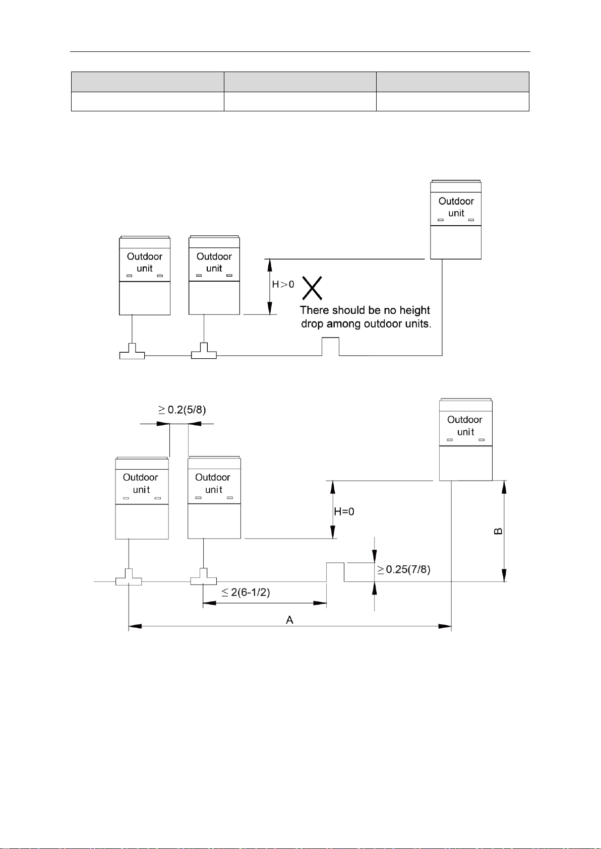
4.3.4 Connection Pipe among Outdoor Modules
NOTICE!
Fig.23
Unit: m (ft.)
Fig.24
When the distance between outdoor units exceeds 2m (6-1/2ft.), U-type oil trap
should be added at low-pressure gas pipe. A+B≤10m (32-7/8ft.).
17
GMV DC Inverter VRF
Basic Module
Pipe between ODU and the first branch of IDU
Gas Pipe mm(in.)
Liquid Pipe mm(in.)
GMV-72WM/B-F(U)
Φ19.05(3/4)
Φ9.52(3/8)
GMV-96WM/B-F(U)
Φ22.2(7/8)
Φ9.52(3/8)
GMV-120WM/B-F(U)
Φ28.6(1-1/8)
Φ12.7(1/2)
GMV-144WM/B1-F(U)
Φ28.6(1-1/8)
Φ12.7(1/2)
GMV-168WM/B1-F(U)
Φ28.6(1-1/8)
Φ15.9(5/8)
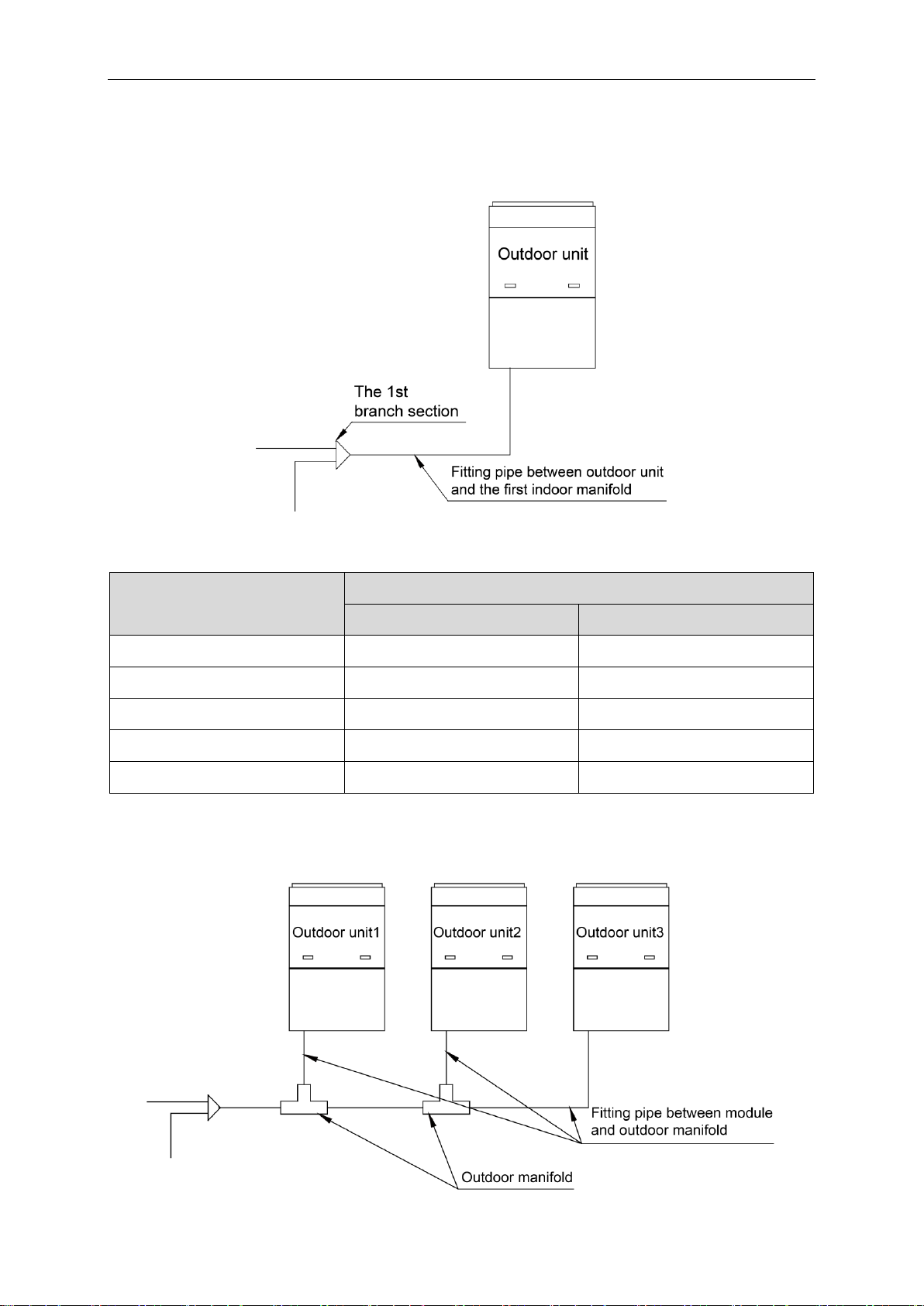
4.3.5 Fitting pipe between Outdoor Unit and the First Manifold
4.3.5.1 For single module system, pipe size (between outdoor unit and the first manifold) is determined by that of outdoor unit.
Fig.25
Pipe size of basic outdoor module is shown as follows:
4.3.5.2 For multi-module unit, select appropriate manifold connected to outdoor module as per the pipe size of basic module. Pipe size of basic outdoor module is shown as follows:
Fig.26
18
 Loading...