

Gree GUHD24ND3FO, GFH24D3FI, GUHD42ND3FO, GUHD48ND3FO, GFH36D3FI Service Manual
...
U-MATCH SERIES DC INVERTER AIR
CONDITIONERS SERVICE MANUAL
T1/R410A/60Hz
(GC201410 - І )

CONTENTE
PRODUCT.................................................................................................................................................................... 2
1 MODELS LIST ................................................................................................................................................. 2
1.1 Outdoor Unit ........................................................................................................................................ 2
1.2 Indoor Unit ........................................................................................................................................... 3
2 NOMENCLATURE .......................................................................................................................................... 4
2.1 Outdoor Unit ........................................................................................................................................ 4
2.2 Indoor Unit ........................................................................................................................................... 4
3 PRODUCT DATA ............................................................................................................................................. 5
3.1 Product Data of Indoor Unit ............................................................................................................. 5
3.2 Operation Range ............................................................................................................................... 11
3.3 Electrical Data ................................................................................................................................... 11
4 PIPING DIAGRAM ........................................................................................................................................ 12
CONTROL.................................................................................................................................................................. 14
1 OPERATION FLOWCHART ........................................................................................................................ 14
1.1 Cooling/Dry Operation .................................................................................................................... 14
1.2 Heating Operation ............................................................................................................................ 15
2 WIRELESS REMOTE CONTROLLER ...................................................................................................... 16
2.1 Operation and Display View .......................................................................................................... 16
3 WIRED CONTROLLER ................................................................................................................................ 18
3.1 Display View ...................................................................................................................................... 18
3.2 Operation View .................................................................................................................................. 20
4 OPERATION INSTRUCTION OF SPECIAL FUNCTIONS ..................................................................... 23
4.1 Setting of Filter Clean Reminder Function ................................................................................ 23
4.2 Low Temperature Drying Function .............................................................................................. 25
4.3 Lock Function ................................................................................................................................... 25
4.4 Memory Function.............................................................................................................................. 26
4.5 Door Control Function/Human Sensitive Function ................................................................. 26
4.6 Switch between Fahrenheit and Centigrade ............................................................................. 26
4.7 Enquiry of Ambient Temperature ................................................................................................. 26
4.8 Enquiry of Historical Malfunction ................................................................................................ 27
4.9 Debugging Function ........................................................................................................................ 27
5 INSTALLATION OF WIRED CONTROLLER ............................................................................................ 31
5.1 Standard Accessories ..................................................................................................................... 31
5.2 Installation Position and Requirement ....................................................................................... 31
5.3 Installation of Wired Controller ..................................................................................................... 32
5.4 Removal of Wired Controller ......................................................................................................... 32
6 TROUBLESHOOTING ................................................................................................................................. 33
6.1 Display of Error Code ...................................................................................................................... 33
7 CENTRALIZED CONTROLLER ................................................................................................................. 34

7.1 Smart Zone Controller ..................................................................................................................... 34
7.2 Additional Special Functions ........................................................................................................ 38
INSTALLATION ......................................................................................................................................................... 53
1 INDOOR UNIT INSTALLATION .................................................................................................................. 53
1.1 Installation of Duct Type ................................................................................................................. 53
1.2 Installation of Floor Ceiling Type ................................................................................................. 62
1.3 Installation of Cassette Type ......................................................................................................... 68
2 OUTDOOR UNIT INSTALLATION.............................................................................................................. 78
2.1 Before Installation ............................................................................................................................ 78
2.2 Installation Site ................................................................................................................................. 78
2.3 Caution for Installation ................................................................................................................... 79
2.4 Dimension Data ................................................................................................................................. 79
3 REFRIGERATION PIPING WORK ............................................................................................................. 80
3.1 Refrigeration Piping Work Procedures and Caution in Connecting ................................... 80
3.2 Specification of Connection Pipe ................................................................................................. 85
4 ELECTRIC WIRING WORK ........................................................................................................................ 85
4.1 Wiring Precautions .......................................................................................................................... 85
4.2 Electrical Wiring................................................................................................................................ 86
MAINTENANCE ........................................................................................................................................................ 94
1 TROUBLE TABLE ......................................................................................................................................... 94
1.1 Main Control Malfunction ............................................................................................................... 94
1.2 Description of Drive Malfunction ................................................................................................. 97
2 FLOW CHART OF TROUBLESHOOTING ............................................................................................... 98
2.1 Troubleshooting Flow Chart of Main Control Malfunction .................................................... 98
2.2 Troubleshooting Flow Chart of Drive Malfunction................................................................. 105
2.3 Interface ............................................................................................................................................ 110
2.4 IPM, PFC Testing Method ............................................................................................................. 116
3 WIRING DIADRAM ..................................................................................................................................... 117
3.1 Outdoor unit ..................................................................................................................................... 117
3.2 Indoor unit ........................................................................................................................................ 120
4 DISASSEMBLY AND ASSEMBLY PROCEDURE OF MAIN PARTS ................................................. 124
4.1 Outdoor Unit .................................................................................................................................... 124
4.2 Indoor Unit ....................................................................................................................................... 128
5 EXPLODED VIEWS AND SPARE PART LIST ....................................................................................... 142
5.1 Outdoor Unit .................................................................................................................................... 142
5.2 Indoor Unit ....................................................................................................................................... 154

U-Match Series DC Inverter Service Manual
1
PRODUCT
U-Match Series DC Inverter Service Manual
2
PRODUCT
1 MODELS LIST
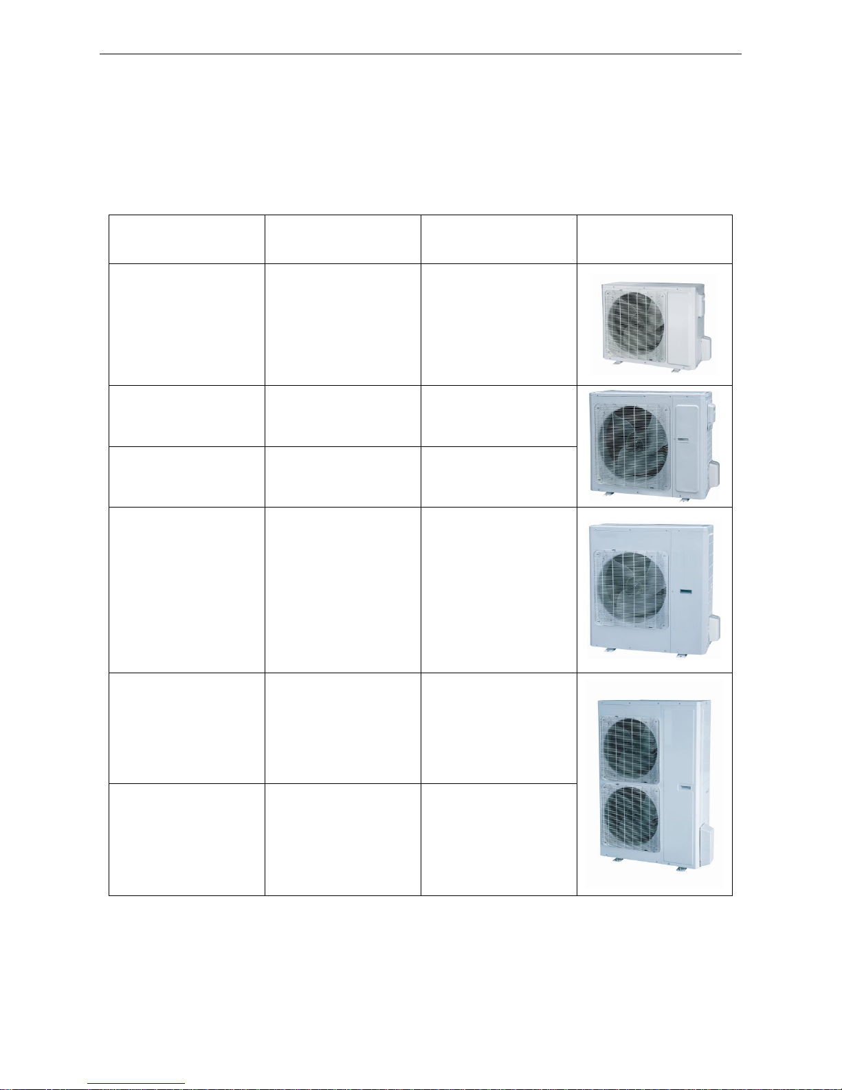
1.1 Outdoor Unit
Model Name
Product Code
Power Supply
(V, Ph, Hz)
Appearance
GUHD18ND3FO
CF090W0751
208/230V~60Hz
GUHD24ND3FO
CF090W0761
208/230V~60Hz
GUHD30ND3FO
CF090W0830
208/230V~60Hz
GUHD36ND3FO
CF090W0771
208/230V~60Hz
GUHD42ND3FO
CF090W0840
208/230V~60Hz
GUHD48ND3FO
CF090W0781
208/230V~60Hz
U-Match Series DC Inverter Service Manual
3
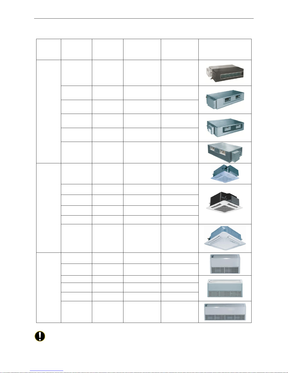
1.2 Indoor Unit
Type
Model Name
Product Code
Nominal Capacity
Cooling/Heating
(Btu/h)
Power Supply
(V, Ph, Hz)
Appearance
Duct
Type
GFH18D3FI
CF060N0512
CF060N0513
17100/18800
208/230V~60Hz
GFH24D3FI
CF060N0522
CF060N0523
23800/27200
208/230V~60Hz
GFH30D3FI
CF060N0580
CF060N0590
28200/31200
208/230V~60Hz
GFH36D3FI
CF060N0532
CF060N0533
34000/41000
208/230V~60Hz
GFH42D3FI
CF060N0600
CF060N0610
39500/44000
208/230V~60Hz
GFH48D3FI
CF060N0542
CF060N0543
48000/54500
208/230V~60Hz
Cassette
Type
GKH18D3FI
ET010N0801
17100/18400
208/230V~60Hz
GKH24D3FI
ET010N0811
23800/27200
208/230V~60Hz
GKH30D3FI
ET010N0840
28200/31200
208/230V~60Hz
GKH36D3FI
ET010N0821
34000/41000
208/230V~60Hz
GKH42D3FI
ET010N0850
39500/44000
208/230V~60Hz
GKH48D3FI
ET010N0831
48000/54500
208/230V~60Hz
Ceiling
Type
GTH18D3FI
ED020N1081
17100/19100
208/230V~60Hz
GTH24D3FI
ED020N1091
23800/27200
208/230V~60Hz
GTH30D3FI
ED020N1120
28200/31200
208/230V~60Hz
GTH36D3FI
ED020N1101
34000/41000
208/230V~60Hz
GTH42D3FI
ED020N1130
39500/44000
208/230V~60Hz
GTH48D3FI
ED020N1111
48000/54500
208/230V~60Hz
Note: 1 Ton =12000Btu/h = 3.517kW
Note: The universal outdoor units means that the customer can choose any of three kind of indoor unit to
match the outdoor unit without any change with it.
U-Match Series DC Inverter Service Manual
4
2 NOMENCLATURE
2.1 Outdoor Unit
G U H D 18 N D 3 F O 1 2 3 4 5 6 7 8 9
10
NO.
Description
Options
1
Gree Electric Appliances Inc
Capital Letter :G 2 Unit Type
U=U-Match Outdoor Unit
3
Product Type
C=Cool Only
H=Heat Pump without Aux Electric Heaters
4
Compressor Power Supply
Type Code
N=Constant Frequency
D=DC Inverter
A=AC Inverter
5
Nominal Cooling Capacity
Nominal Cooling Capacity=Number×1000Btu/h
6
Climate Type
N=Climate T1 Condition
T= Climate T3 Condition
7
Power Supply Code
K= 220-240V~ 50Hz
M=380-415V 3N~ 50Hz
D=208/230V ~ 60Hz
8
Refrigerant
1 =R22; 2=R407C; 3=R410A
9
Design Code
Design Code: A, B, C, D……
Design Change Code=0 (default)
1,2,3......
10
Unit Code
O=Outdoor unit
2.2 Indoor Unit
G F H
18 T D 3 F I 1 2 3 4 5 6 7 8 9 NO.
Description
Options
1
Gree Electric Appliances Inc
Capital Letter: G 2 Unit Type
F=Duct Type; K=Cassette Type; T=Floor-ceiling Type
3
Product Type
C=Cool Only; H=Heat Pump without Aux Electric Heaters
4
Nominal Cooling Capacity
Nominal Cooling Capacity=Number×1000Btu/h
5
Climate Type
Omit=Climate T1 Condition;
T=Climate T3 Condition
6
Power Supply Code
K=220-240V~ 50Hz
M=380-415V 3N~ 50Hz
D=208/230V ~ 60Hz
7
Refrigerant
1=R22; 2=R407C; 3=R410A
8
Design Code
Design Code: A, B, C, D……
Design Change Code=0 (default)
1,2,3...... 9 Unit Code
I=indoor unite
U-Match Series DC Inverter Service Manual
5
3 PRODUCT DATA
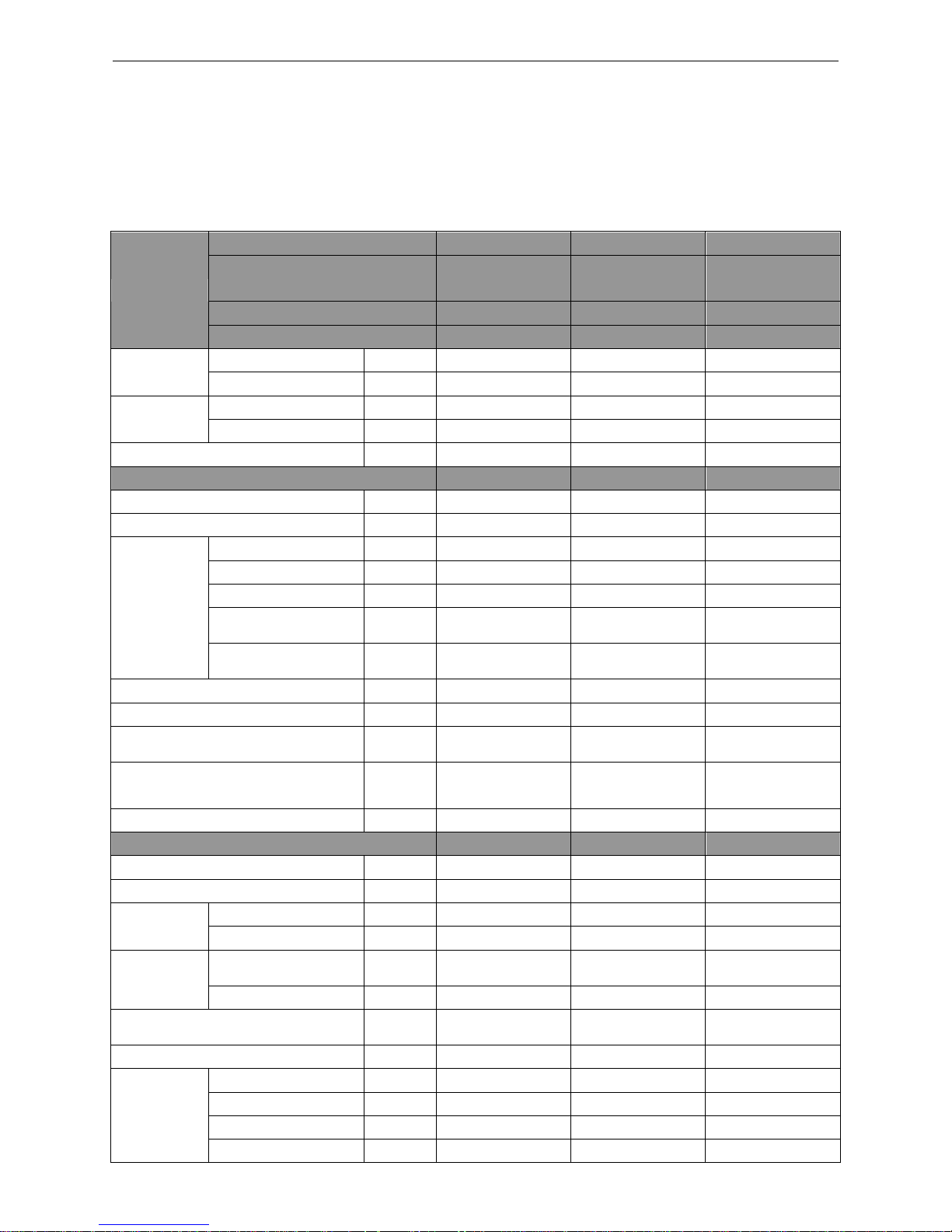
3.1 Product Data of Indoor Unit
3.1.1 Duct Type
Model
Indoor unit
GFH18D3FI
GFH24D3FI
GFH30D3FI
Product Code
CF060N0512
CF060N0513
CF060N0522
CF060N0523
CF060N0580
CF060N0590
Outdoor unit
GUHD18ND3FO
GUHD24ND3FO
GUHD30ND3FO
Product Code
CF090W0751
CF090W0761
CF090W0830
Capacity
Cooling Capacity
Btu/h
17100(5400~19800)
23800(7400~29000)
28200(8200~29600)
Heating Capacity
Btu/h
18800(4700~23200)
27200(8200~32400)
31200(8200~33600)
Power Input
Cooling
kW
1.55(0.55~1.75)
2.23(0.85~2.50)
3.30(0.85~3.70)
Heating
kW
1.65(0.50~1.90)
2.36(0.80~2.75)
3.10(0.80~3.50)
SEER / HSPF
(Btu/h)/W
16.00/9.50
16.00/9.00
16.00/9.00
Indoor Unit
GFH18D3FI
GFH24D3FI
GFH30D3FI
Power Supply
V/Ph/Hz
208/230V~60Hz
208/230V~60Hz
208/230V~60Hz
Heat Exchange
-
Cross Fin Coil
Cross Fin Coil
Cross Fin Coil
Fan
Drive
-
Direct
Direct
Direct
Motor Output
kW
0.06×1
0.15×1
0.15×1
Air Flow
m3/h(CFM)
1000(585)
1400(820)
1400(820)
Rated Ext. Static
Pressure
Pa(InWg)
25(0.1)
25(0.1)
37(0.15)
Ext. Static Pressure
Range
Pa(InWg)
0~30(0~0.12)
0~75(0~0.3)
0~75(0~0.3)
Sound Pressure Level(SS/H/M/L)
dB(A)
40/39/36/28
47/46/44/40
47/46/44/40
Air Filter
-
PP
PPKZ
PPKZ
Drain Piping
mm(inch)
Φ30×1.5
(φ1.18×0.06)
Φ20×1.2
(φ0.79×0.05)
Φ20×1.2
(φ0.79×0.05)
Outline Dimensions (W×H×D)
mm
(inch)
1037×266×721
(40.8×10.5×28.4)
1279×268×558
(50.4×10.6×22.0)
1279×268×558
(50.4×10.6×22.0)
Net Weight
kg(lb)
33.0(72.8)
34.0(75.0)
35.0(77.2)
Outdoor Unit
GUHD18ND3FO
GUHD24ND3FO
GUHD30ND3FO
Power Supply
V/Ph/Hz
208/230V~60Hz
208/230V~60Hz
208/230V~60Hz
Heat Exchange
-
Cross Fin Coil
Cross Fin Coil
Cross Fin Coil
Compressor
Type
-
Rotary
Rotary
Rotary
Power Input
W
1440
2550
2550
Refrigerant
Control
-
Electronic Expansion
Valve
Electronic Expansion
Valve
Electronic Expansion
Valve
Charge
kg(oz)
1.4(49.4)
2.2(77.6)
2.4(84.7)
Outline Dimensions (W×H×D)
mm(inch)
955×700×396
(37.6×27.6×15.6)
980×790×427
(38.6×31.1×16.8)
980×790×427
(38.6×31.1×16.8)
Net Weight
kg(lb)
48.0(105.8)
69.0(152.1)
72.0(158.8)
Piping
Connections
Liquid
Inch
Φ1/4
Φ3/8
Φ3/8
Gas
Inch
Φ1/2
Φ5/8
Φ5/8
Max. Length
m(ft)
20(65.6)
30(98.4)
30(98.4)
Max. Height
m(ft)
15(49.2)
15(49.2)
15(49.2)
U-Match Series DC Inverter Service Manual
6
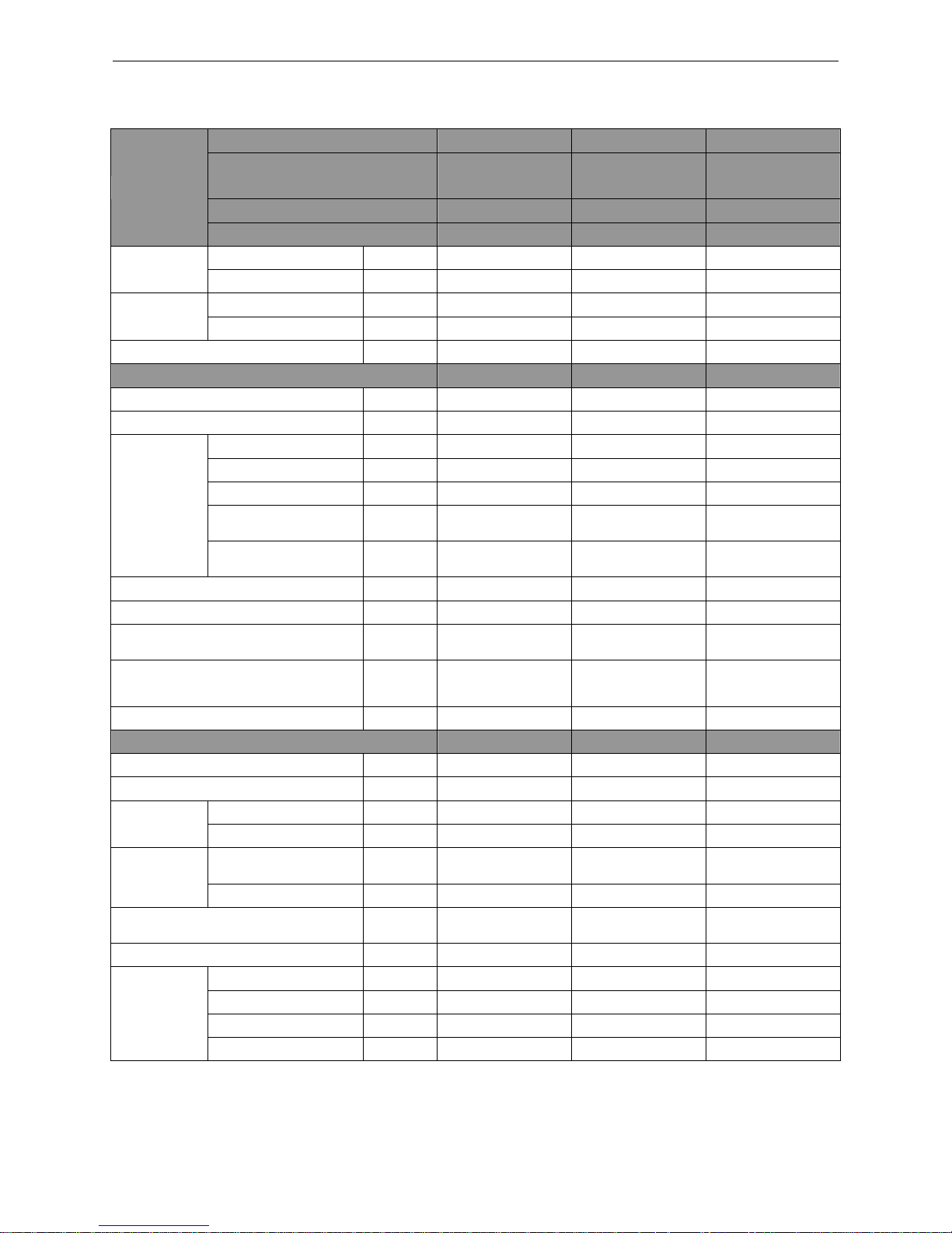
Model
Indoor unit
GFH36D3FI
GFH42D3FI
GFH48D3FI
Product Code
CF060N0532
CF060N0533
CF060N0600
CF060N0610
CF060N0542
CF060N0543
Outdoor unit
GUHD36ND3FO
GUHD42ND3FO
GUHD48ND3FO
Product Code
CF090W0771
CF090W0840
CF090W0781
Capacity
Cooling Capacity
Btu/h
34000(10800~39000)
39500(12000~42500)
48000(20400~49500)
Heating Capacity
Btu/h
41000(9800~49500)
44000(13000~52500)
54500(17500~58000)
Power Input
Cooling
kW
3.28(0.70~4.50)
4.15(0.65~4.70)
5.15(1.40~5.60)
Heating
kW
3.75(0.70~4.60)
3.90(0.76~4.75)
5.15(1.30~5.50)
SEER / HSPF
(Btu/h)/W
16.00/9.00
16.00/9.00
16.00/9.00
Indoor Unit
GFH36D3FI
GFH42D3FI
GFH48D3FI
Power Supply
V/Ph/Hz
208/230V~60Hz
208/230V~60Hz
208/230V~60Hz
Heat Exchange
-
Cross Fin Coil
Cross Fin Coil
Cross Fin Coil
Fan
Drive
-
Direct
Direct
Direct
Motor Output
kW
0.25×1
0.25×1
0.56×1
Air Flow
m3/h(CFM)
2000(1175)
2000(1175)
2500(1470)
Rated Ext. Static
Pressure
Pa(InWg)
37(0.15)
37(0.15)
50(0.2)
Ext. Static Pressure
Range
Pa(InWg)
0~100(0~0.4)
0~100(0~0.4)
0~125(0~0.5)
Sound Pressure Level(SS/H/M/L)
dB(A)
53/52/48/44
53/52/48/44
55/53/49/45
Air Filter
-
PPKZ
PPKZ
PPKZ
Drain Piping
mm(inch)
Φ20×1.2
(φ0.79×0.05)
Φ20×1.2
(φ0.79×0.05)
Φ20×1.2
(φ0.79×0.05)
Outline Dimensions (W×H×D)
mm
(inch)
1226×290×775
(48.3×11.4×30.5)
1226×290×775
(48.3×11.4×30.5)
1340×350×750
(52.8×13.8×29.5)
Net Weight
kg(lb)
46.0(101.4)
46.0(101.4)
56.0(123.5)
Outdoor Unit
GUHD36ND3FO
GUHD42ND3FO
GUHD48ND3FO
Power Supply
V/Ph/Hz
208/230V~60Hz
208/230V~60Hz
208/230V~60Hz
Heat Exchange
-
Cross Fin Coil
Cross Fin Coil
Cross Fin Coil
Compressor
Type
-
Rotary
Rotary
Rotary
Power Input
W
4150
4150
4580
Refrigerant
Control
-
Electronic Expansion
Valve
Electronic Expansion
Valve
Electronic Expansion
Valve
Charge
kg(oz)
3.5(123.5)
3.7(130.5)
4.0(141.1)
Outline Dimensions (W×H×D)
mm(inch)
1107×1100×440
(43.6×43.3×17.3)
958×1349×412
(37.7×53.1×16.2)
958×1349×412
(37.7×53.1×16.2)
Net Weight
kg(lb)
93.0(205.1)
95.0(209.5)
105.0(231.5)
Piping
Connections
Liquid
Inch
Φ3/8
Φ3/8
Φ3/8
Gas
Inch
Φ5/8
Φ5/8
Φ5/8
Max. Length
m(ft)
30(98.4)
50(164.0)
50(164.0)
Max. Height
m(ft)
15(49.2)
30(98.4)
30(98.4)
U-Match Series DC Inverter Service Manual
7
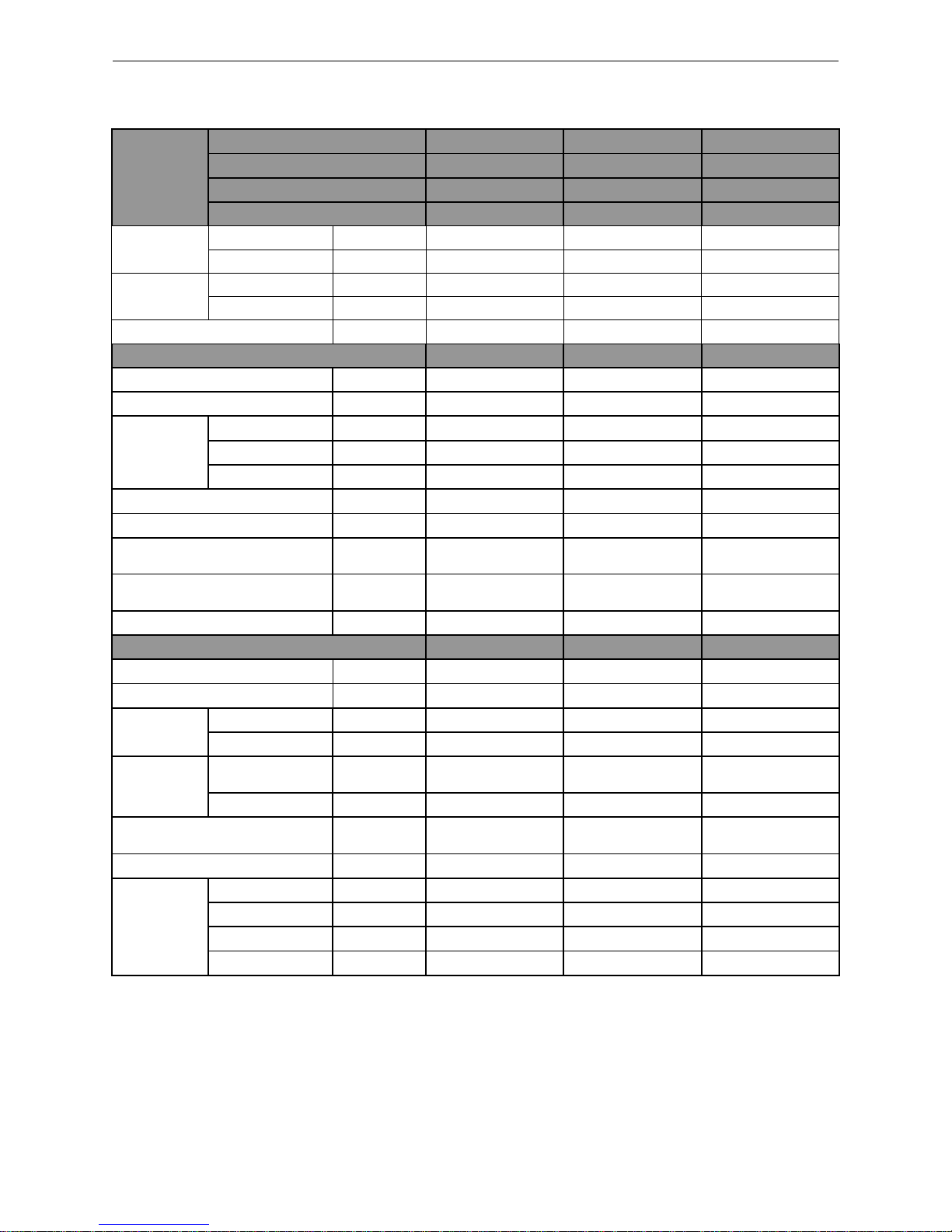
3.1.2 Cassette Type
Model
Indoor unit
GKH18D3FI
GKH24D3FI
GKH30D3FI
Product Code
ET010N0801
ET010N0811
ET010N0840
Outdoor unit
GUHD18ND3FO
GUHD24ND3FO
GUHD30ND3FO
Product Code
CF090W0751
CF090W0761
CF090W0830
Capacity
Cooling Capacity
Btu/h
17100(5400~18700)
23800(8200~29000)
28200(8800~31400)
Heating Capacity
Btu/h
18400(4700~22200)
27200(8200~32400)
31200(8200~33600)
Power Input
Cooling
kW
1.70(0.55~1.75)
2.23(0.85~2.50)
2.70(0.85~3.70)
Heating
kW
1.80(0.50~1.90)
2.36(0.80~2.75)
2.50(0.80~3.50)
SEER / HSPF
(Btu/h)/W
16.00/9.50
16.00/9.00
17.00/9.00
Indoor Unit
GKH18D3FI
GKH24D3FI
GKH30D3FI
Power Supply
V/Ph/Hz
208/230V~ 60Hz
208/230V~ 60Hz
208/230V~ 60Hz
Heat Exchange
-
Cross Fin Coil
Cross Fin Coil
Cross Fin Coil
Fan
Drive - Direct
Direct
Direct
Motor Output
kW
0.045×1
0.045×1
0.075×1
Air Flow
m3/h(CFM)
760(445)
1300(765)
1500(880)
Sound Pressure Level(SS/H/M/L)
dB(A)
47/46/44/37
47/46/42/38
49/48/45/40
Air Filter
-
PP
ABS+PP
ABS+PP
Drain Piping
mm(inch)
Φ25×1.5
(φ0.98×0.06)
Φ25×1.5
(φ0.98×0.06)
Φ25×1.5
(φ0.98×0.06)
Outline Dimensions (W×H×D)
mm(inch)
665×240×596
(26.2×9.4×23.5)
917×240×840
(36.1×9.4×33.1)
917×320×840
(36.1×12.6×33.1)
Net Weight
kg(lb)
20.0(44.1)
27.0(59.5)
32.0(70.6)
Outdoor Unit
GUHD18ND3FO
GUHD24ND3FO
GUHD30ND3FO
Power Supply
V/Ph/Hz
208/230V~ 60Hz
208/230V~ 60Hz
208/230V~ 60Hz
Heat Exchange
-
Cross Fin Coil
Cross Fin Coil
Cross Fin Coil
Compressor
Type
-
Rotary
Rotary
Rotary
Power Input
W
1440
2550
2550
Refrigerant
Control
-
Electronic
Expansion Valve
Electronic
Expansion Valve
Electronic
Expansion Valve
Charge
kg(oz)
1.4(49.4)
2.2(77.6)
2.4(84.7)
Outline Dimensions (W×H×D)
mm(inch)
955×700×396
(37.6×27.6×15.6)
980×790×427
(38.6×31.1×16.8)
980×790×427
(38.6×31.1×16.8)
Net Weight
kg(lb)
48.0(105.8)
69.0(152.1)
72.0(158.8)
Piping
Connections
Liquid
Inch
Φ1/4
Φ3/8
Φ3/8
Gas
Inch
Φ1/2
Φ5/8
Φ5/8
Max. Length
m(ft)
20(65.6)
30(98.4)
30(98.4)
Max. Height
m(ft)
15(49.2)
15(49.2)
15(49.2)
U-Match Series DC Inverter Service Manual
8
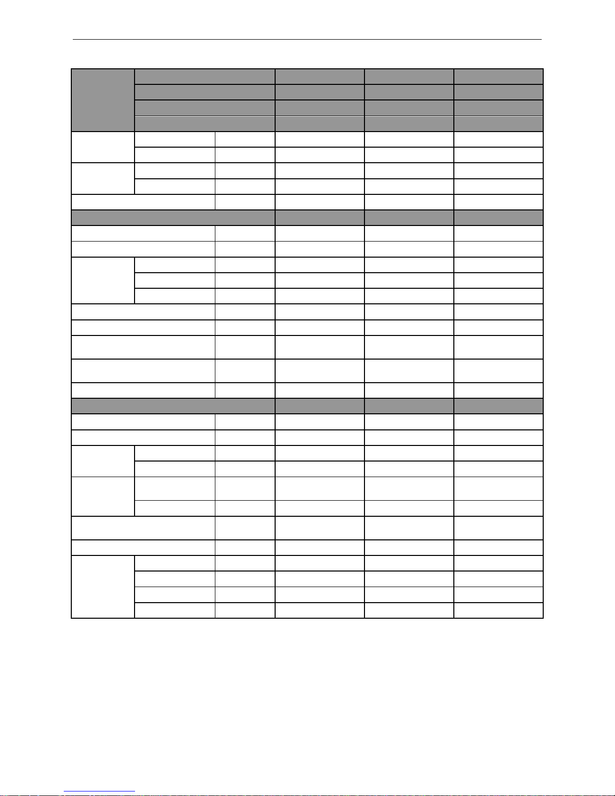
Model
Indoor unit
GKH36D3FI
GKH42D3FI
GKH48D3FI
Product Code
ET010N0821
ET010N0850
ET010N0831
Outdoor unit
GUHD36ND3FO
GUHD42ND3FO
GUHD48ND3FO
Product Code
CF090W0771
CF090W0840
CF090W0781
Capacity
Cooling Capacity
Btu/h
34000(10800~39000)
39500(11000~41000)
48000(20400~50500)
Heating Capacity
Btu/h
41000(9800~49500)
44000(12000~51000)
54500(17500~61500)
Power Input
Cooling
kW
3.28(0.75~4.50)
4.40(0.53~4.65)
5.50(1.30~5.70)
Heating
kW
3.75(0.60~4.80)
4.45(0.64~4.80)
4.80(1.20~5.40)
SEER / HSPF
(Btu/h)/W
16.00/9.00
16.00/9.00
16.00/9.00
Indoor Unit
GKH36D3FI
GKH42D3FI
GKH48D3FI
Power Supply
V/Ph/Hz
208/230V~ 60Hz
208/230V~ 60Hz
208/230V~ 60Hz
Heat Exchange
-
Cross Fin Coil
Cross Fin Coil
Cross Fin Coil
Fan
Drive - Direct
Direct
Direct
Motor Output
kW
0.075×1
0.075×1
0.1×1
Air Flow
m3/h(CFM)
1860(1095)
1860(1095)
2300(1350)
Sound Pressure Level(SS/H/M/L)
dB(A)
51/49/46/43
51/49/46/43
53/52/47/41
Air Filter
-
ABS+PP
ABS+PP
ABS+PP
Drain Piping
mm(inch)
Φ25×1.5
(φ0.98×0.06)
Φ25×1.5
(φ0.98×0.06)
Φ25×1.5
(φ0.98×0.06)
Outline Dimensions (W×H×D)
mm(inch)
917×320×840
(36.1×12.6×33.1)
917×320×840
(36.1×12.6×33.1)
910×290×910
(35.8×11.4×35.8)
Net Weight
kg(lb)
32.0(70.6)
32.0(70.6)
43.0(94.8)
Outdoor Unit
GUHD36ND3FO
GUHD42ND3FO
GUHD48ND3FO
Power Supply
V/Ph/Hz
208/230V~ 60Hz
208/230V~ 60Hz
208/230V~ 60Hz
Heat Exchange
-
Cross Fin Coil
Cross Fin Coil
Cross Fin Coil
Compressor
Type - Rotary
Rotary
Rotary
Power Input
W
4150
4150
4580
Refrigerant
Control
-
Electronic
Expansion Valve
Electronic
Expansion Valve
Electronic
Expansion Valve
Charge
kg(oz)
3.5(123.5)
3.7(130.5)
4.0(141.1)
Outline Dimensions (W×H×D)
mm(inch)
1107×1100×440
(43.6×43.3×17.3)
958×1349×412
(37.7×53.1×16.2)
958×1349×412
(37.7×53.1×16.2)
Net Weight
kg(lb)
93.0(205.1)
95.0(209.5)
105.0(231.5)
Piping
Connections
Liquid
Inch
Φ3/8
Φ3/8
Φ3/8
Gas
Inch
Φ5/8
Φ5/8
Φ5/8
Max. Length
m(ft)
30(98.4)
50(164.0)
50(164.0)
Max. Height
m(ft)
15(49.2)
30(98.4)
30(98.4)
U-Match Series DC Inverter Service Manual
9
3.1.3 Floor-ceiling Type
Model
Indoor unit
GTH18D3FI
GTH24D3FI
GTH30D3FI
Product Code
ED020N1081
ED020N1091
ED020N1120
Outdoor unit
GUHD18ND3FO
GUHD24ND3FO
GUHD30ND3FO
Product Code
CF090W0751
CF090W0761
CF090W0830
Capacity
Cooling Capacity
Btu/h
17100(5400~19800)
23800(8200~27800)
28200(8800~31400)
Heating Capacity
Btu/h
19100(4700~23200)
27200(8200~30600)
31200(8200~33600)
Power Input
Cooling
kW
1.55(0.55~1.75)
2.23(0.85~2.50)
2.40(0.85~3.70)
Heating
kW
1.55(0.50~1.90)
2.36(0.80~2.75)
2.60(0.80~3.50)
SEER / HSPF
(Btu/h)/W
17.00/9.50
16.00/9.00
17.00/9.00
Indoor Unit
GTH18D3FI
GTH24D3FI
GTH30D3FI
Power Supply
V/Ph/Hz
208/230V~ 60Hz
208/230V~ 60Hz
208/230V~ 60Hz
Heat Exchange
-
Cross Fin Coil
Cross Fin Coil
Cross Fin Coil
Fan
Drive - Direct
Direct
Direct
Motor Output
kW
0.06×1
0.06×1
0.15×1
Air Flow
m3/h(CFM)
1000(585)
1200(705)
1500(880)
Sound Pressure Level(SS/H/M/L)
dB(A)
44/42/38/32
49/48/46/40
49/46/44/38
Air Filter
-
PP
PP
PP
Drain Piping
mm(inch)
Φ17×1.75
(φ0.67×0.07)
Φ17×1.75
(φ0.67×0.07)
Φ17×1.75
(φ0.67×0.07)
Outline Dimensions (W×H×D)
mm(inch)
1220×225×700
(48.0×8.9×27.6)
1220×225×700
(48.0×8.9×27.6)
1420×245×700
(55.9×9.6×27.6)
Net Weight
kg(lb)
39.0(86.0)
40.0(88.2)
48.0(105.8)
Outdoor Unit
GUHD18ND3FO
GUHD24ND3FO
GUHD30ND3FO
Power Supply
V/Ph/Hz
208/230V~ 60Hz
208/230V~ 60Hz
208/230V~ 60Hz
Heat Exchange
-
Cross Fin Coil
Cross Fin Coil
Cross Fin Coil
Compressor
Type - Rotary
Rotary
Rotary
Power Input
W
1440
2550
2550
Refrigerant
Control
-
Electronic Expansion
Valve
Electronic Expansion
Valve
Electronic Expansion
Valve
Charge
kg(oz)
1.4(49.4)
2.2(77.6)
2.4(84.7)
Outline Dimensions (W×H×D)
mm(inch)
955×700×396
(37.6×27.6×15.6)
980×790×427
(38.6×31.1×16.8)
980×790×427
(38.6×31.1×16.8)
Net Weight
kg(lb)
48.0(105.8)
69.0(152.1)
72.0(158.8)
Piping
Connections
Liquid
Inch
Φ1/4
Φ3/8
Φ3/8
Gas
Inch
Φ1/2
Φ5/8
Φ5/8
Max. Length
m(ft)
20(65.6)
30(98.4)
30(98.4)
Max. Height
m(ft)
15(49.2)
15(49.2)
15(49.2)
U-Match Series DC Inverter Service Manual
10
Model
Indoor unit
GTH36D3FI
GTH42D3FI
GTH48D3FI
Product Code
ED020N1101
ED020N1130
ED020N1111
Outdoor unit
GUHD36ND3FO
GUHD42ND3FO
GUHD48ND3FO
Product Code
CF090W0771
CF090W0840
CF090W0781
Capacity
Cooling Capacity
Btu/h
34000(10800~39000)
39500(12000~42500)
48000(20400~50500)
Heating Capacity
Btu/h
41000(9800~49500)
44000(13000~52500)
54500(17500~61500)
Power Input
Cooling
kW
3.28(0.80~4.60)
4.05(0.60~4.70)
4.95(1.30~5.50)
Heating
kW
3.75(0.65~4.80)
4.05(0.69~4.80)
4.60(1.20~5.40)
SEER / HSPF
(Btu/h)/W
16.00/9.00
16.00/9.00
16.00/9.00
Indoor Unit
GTH36D3FI
GTH42D3FI
GTH48D3FI
Power Supply
V/Ph/Hz
208/230V~ 60Hz
208/230V~ 60Hz
208/230V~ 60Hz
Heat Exchange
-
Cross Fin Coil
Cross Fin Coil
Cross Fin Coil
Fan
Drive - Direct
Direct
Direct
Motor Output
kW
0.15×1
0.15×1
0.25×1
Air Flow
m3/h(CFM)
1900(1115)
1900(1115)
2300(1350)
Sound Pressure Level(SS/H/M/L)
dB(A)
54/53/51/46
55/54/52/47
56/55/50/46
Air Filter
-
PP
PP
PP
Drain Piping
mm(inch)
Φ17×1.75
(φ0.67×0.07)
Φ17×1.75
(φ0.67×0.07)
Φ17×1.75
(φ0.67×0.07)
Outline Dimensions (W×H×D)
mm(inch)
1420×245×700
(55.9×9.6×27.6)
1420×245×700
(55.9×9.6×27.6)
1700×245×700
(66.9×9.6×27.6)
Net Weight
kg(lb)
48.0(105.8)
50.0(110.3)
59.0(130.1)
Outdoor Unit
GUHD36ND3FO
GUHD42ND3FO
GUHD48ND3FO
Power Supply
V/Ph/Hz
208/230V~ 60Hz
208/230V~ 60Hz
208/230V~ 60Hz
Heat Exchange
-
Cross Fin Coil
Cross Fin Coil
Cross Fin Coil
Compressor
Type - Rotary
Rotary
Rotary
Power Input
W
4150
4150
4580
Refrigerant
Control
-
Electronic Expansion
Valve
Electronic Expansion
Valve
Electronic Expansion
Valve
Charge
kg(oz)
3.5(123.5)
3.7(130.5)
4.0(141.1)
Outline Dimensions (W×H×D)
mm(inch)
1107×1100×440
(43.6×43.3×17.3)
958×1349×412
(37.7×53.1×16.2)
958×1349×412
(37.7×53.1×16.2)
Net Weight
kg(lb)
93.0(205.1)
95.0(209.5)
105.0(231.5)
Piping
Connections
Liquid
Inch
Φ3/8
Φ3/8
Φ3/8
Gas
Inch
Φ5/8
Φ5/8
Φ5/8
Max. Length
m(ft)
30(98.4)
50(164.0)
50(164.0)
Max. Height
m(ft)
15(49.2)
30(98.4)
30(98.4)
Note:
Nominal capacities are based on the follow conditions.
Indoor
Outdoor
Cooling
DB: 26.7℃(80.0℉)
WB: 19.4℃(67.0℉)
DB: 35.0℃(95.0℉)
WB: 23.9℃(75.0℉)
Heating
DB: 21.1℃(70.0℉)
WB: 15.6℃(60.0℉)
DB: 8.33℃(47.0℉)
WB: 6.11℃(43.0℉)
Piping Length
18k~48k units
7.6m(25.0ft)
The air volume is measured at the relevant standard external static pressure.
Noise is tested in the Semi anechoic room, so it should be slightly higher in the actual operation due to
environmental change.
U-Match Series DC Inverter Service Manual
11
3.2 Operation Range
Mode
Range of Outdoor Temperature
Cooling
-18.0℃(0℉)~48.0℃(118.4℉)
Heating
-18.0℃(0℉)~24.0℃(75.2℉)
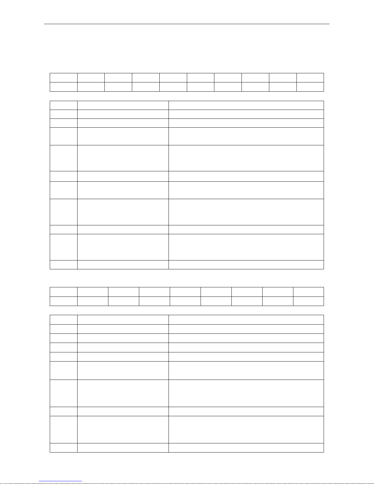
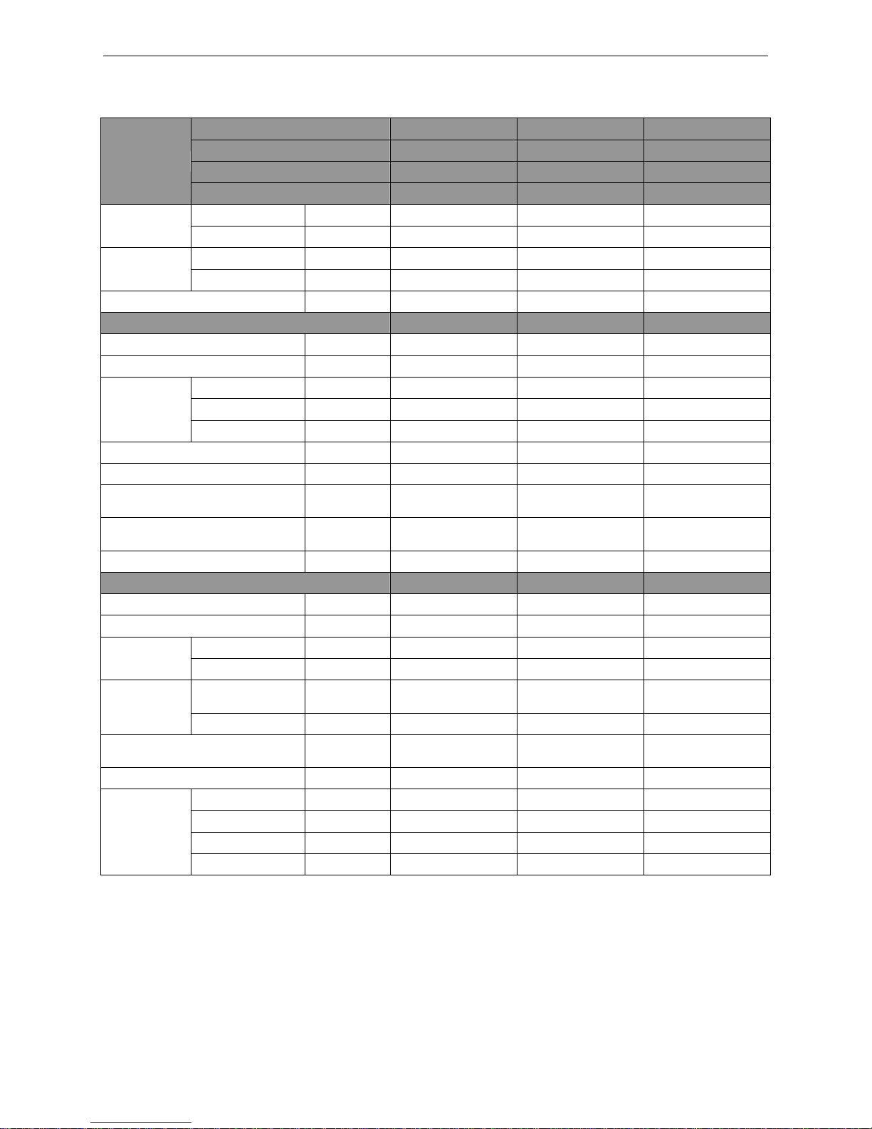
3.3 Electrical Data
3.3.1 Outdoor unit
Table 1-3-1 Electrical Data of Outdoor Unit
Model
Compressor
Fan Motor
Fuse/Breaker
Capacity
Minimum
Circuit
Ampacity
Maximum
Overcurrent
Protection
Power Supply
Qty.
RLA
FLA
V/Ph/Hz
− A A A A A GUHD18ND3FO
208/230V ~ 60Hz
1
12.0
1.5
5/25
17
25
GUHD24ND3FO
208/230V ~ 60Hz
1
18.0
1.5
5/40
24
40
GUHD30ND3FO
208/230V ~ 60Hz
1
18.0
1.5
5/40
24
40
GUHD36ND3FO
208/230V ~ 60Hz
1
21.2
2.0
5/45
29
45
GUHD42ND3FO
208/230V ~ 60Hz
1
21.2
2*2.0
5/50
31
50
GUHD48ND3FO
208/230V ~ 60Hz
1
32.5
2*2.0
5/70
45
70
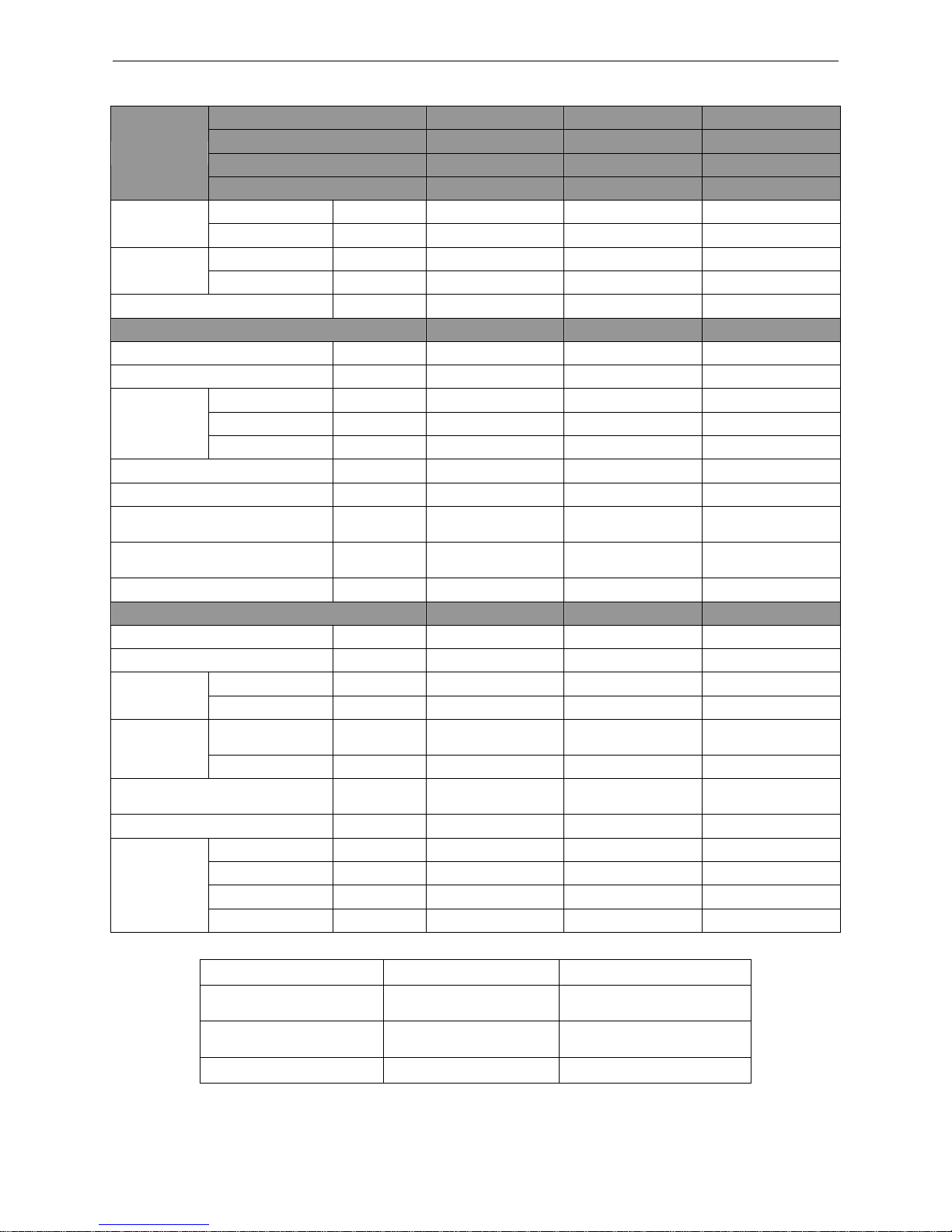
3.3.2 Indoor unit
Table 1-3-2 Electrical Data of Indoor Unit
Model
Power Supply
Fan Motor FLA
Fuse/Breaker
Capacity
Minimum Circuit
Ampacity
Maximum
Overcurrent
Protection
V/Ph/Hz
A A A
A
GFH18D3FI
208V/230V ~ 60Hz
0.6
5/15
1
15
GFH24D3FI
208V/230V ~ 60Hz
1.3
5/15
2
15
GFH30D3FI
208V/230V ~ 60Hz
1.3
5/15
2
15
GFH36D3FI
208V/230V ~ 60Hz
2.1
5/15
3
15
GFH42D3FI
208V/230V ~ 60Hz
2.1
5/15
3
15
GFH48D3FI
208V/230V ~ 60Hz
4.0
5/15
5
15
GKH18D3FI
208V/230V ~ 60Hz
0.5
5/15
1
15
GKH24D3FI
208V/230V ~ 60Hz
0.5
5/15
1
15
GKH30D3FI
208V/230V ~ 60Hz
0.9
5/15
1.5
15
GKH36D3FI
208V/230V ~ 60Hz
0.9
5/15
1.5
15
GKH42D3FI
208V/230V ~ 60Hz
0.9
5/15
1.5
15
GKH48D3FI
208V/230V ~ 60Hz
1.5
5/15
2
15
GTH18D3FI
208V/230V ~ 60Hz
0.6
5/15
1
15
GTH24D3FI
208V/230V ~ 60Hz
0.6
5/15
1
15
GTH30D3FI
208V/230V ~ 60Hz
1.4
5/15
2
15
GTH36D3FI
208V/230V ~ 60Hz
1.4
5/15
2
15
GTH42D3FI
208V/230V ~ 60Hz
1.4
5/15
2
15
GTH48D3FI
208V/230V ~ 60Hz
2.1
5/15
3
15
U-Match Series DC Inverter Service Manual
12
Notes:
RLA: Rated load amperes (marked in the nameplate of the outdoor unit)
FLA: Full load current
① The fuse is located on the main board.
② Install the disconnect device with a contact gap of at least 3mm (1/8inch) in all poles nearby
the units (Both indoor unit and outdoor unit).The appliance must be positioned so that the
plug is accessible.
③ Take 2 pieces of power cord of 0.75mm2 (AWG18) as the communication lines between
indoor and outdoor unit, with their longest lengths of 50m (164feet). Please select the
appropriate line length as per the actual installation conditions. The communication lines can
not be twisted together. For the unit (≤30k), it’s recommended to use 8m (26-1/4feet) long
communication line.
④ Take 2 pieces of power cord of 0.75mm2 (AWG18) as the communication lines between the
wired controller and the indoor unit, with their longest lengths of 30m (98-2/5feet). Please
select the appropriate line length as per the actual installation conditions. The
communication lines can not be twisted together. It’s recommended to use 8m (26-1/4feet)
long communication line.
⑤ The wire size of the communication line should be no less than 0.75mm2 (AWG18). It’s
recommended to take 0.75mm2 (AWG18) power cords as the communication line.
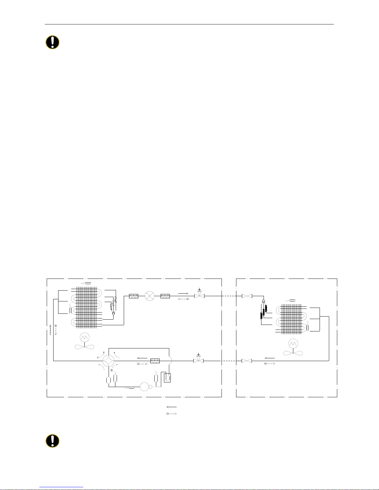
4 PIPING DIAGRAM
Indoor Unit
Outdoor Unit
TH-OE
TH-D
Condenser
Filter
Electronic Expansion Valve
Liquid Solid Valve
with Service Port
Liquid Solid
Valve
4-Way Valve
Muffler
TH-C
Low Pressure Switch
Accumulator
High Pressure
Switch
Compressor
Gas Stop Valve
with Service Port
Gas Stop
Valve
TH-IE
Evaporator
TH-E
Cooling
Heating
TH-OE: Outdoor Environment Thermal Bulb
TH-C: Outdoor Condenser Thermal Bulb
TH-D: Compressor Discharge Thermal Bulb
TH-IE: Indoor Environment Thermal Bulb
TH-E: Indoor Evaporator Thermal Bulb
Filter
Filter
Notes:
It is just a schematic diagram and some parts may differ from the real objects inside the unit.

U-Match Series DC Inverter Service Manual
13
CONTROL
U-Match Series DC Inverter Service Manual
14
CONTROL
1 OPERATION FLOWCHART
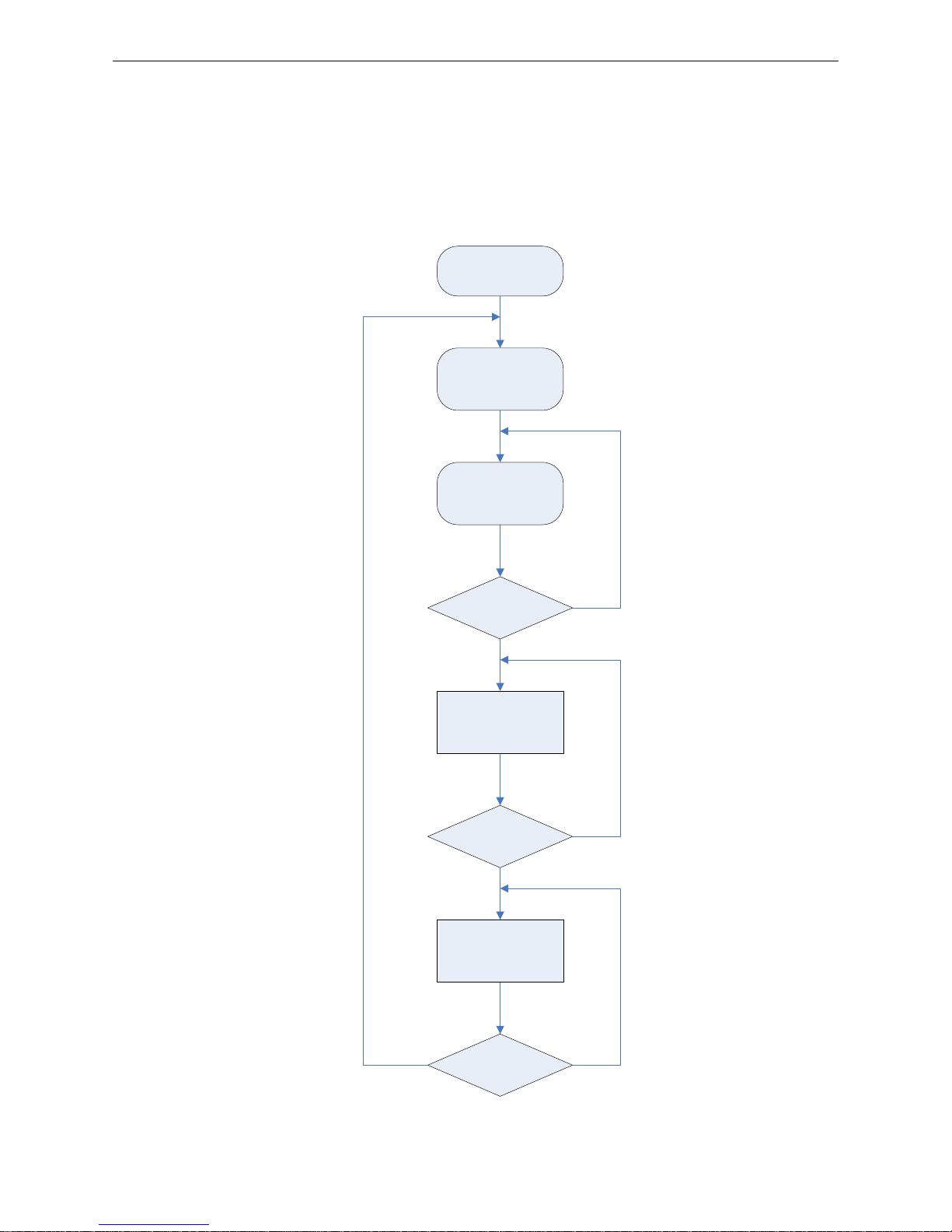
1.1 Cooling/Dry Operation
Satisfying open
Comp. condition
Temp of indoor
≤Set temp
Comp. stop
for 3 min
NY
N
Y
Y
N
Open unit running at
cool or dry mode
Indoor fan run
Comp. and outdoor
fan run
Comp. and
outdoor fan stop
Power
On
U-Match Series DC Inverter Service Manual
15
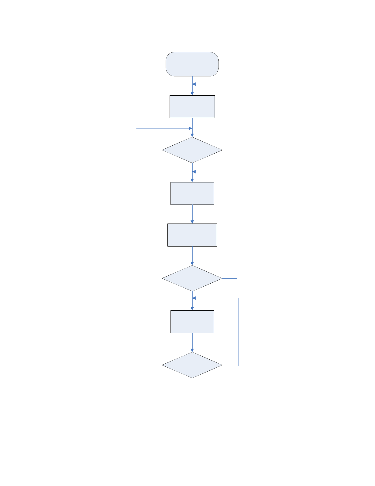
1.2 Heating Operation
Satisfying open
comp. condition
N
Y
N
Y
Y
N
Power
On
Comp. and
outdoor
fan run
Avoid cool wind
(only when comp.
start)
Temp of indoor
≥Set temp
Comp. and
outdoor fan stop
Comp. stop
for 3 min
Open unit running
at heat mode
U-Match Series DC Inverter Service Manual
16
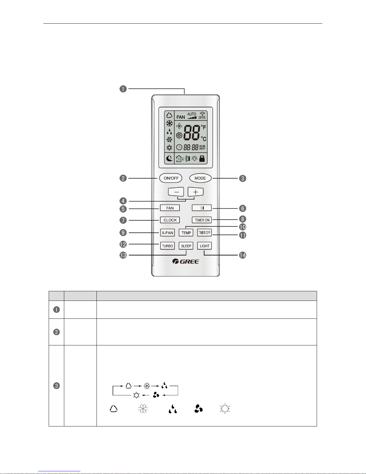
2 WIRELESS REMOTE CONTROLLER
2.1 Operation and Display View
Table 2-2-1 Operation instruction of wireless remote controller
No.
Name
Function Description
Signal
transmitter
Signal transmitter
ON/OFF
button
Press this button and the unit will be turned on; press it once more and the unit will be
turned off. When turning off the unit, the Sleep function will be canceled, but the
presetting time is still remained.
MODE
button
By pressing this button, Auto, Cool, Dry, Fan, Heat mode can be selected circularly.
Auto mode is default after power on. Under the Auto mode, the setting temperature will
not be displayed; Under the Heat mode, the initial value is 28°C (82°F); under other
modes, the initial value is 25°C (77°F).
AUTO; COOL; DRY; FAN; HEAT (only for cooling and heating
unit)
U-Match Series DC Inverter Service Manual
17
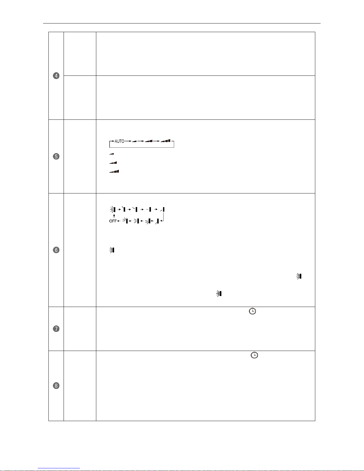
- button
Preset temperature can be decreased by pressing this button. Pressing and holding this
button for more than 2 seconds can make the temperature changed quickly until release
this button and then transmit this order. The temperature adjustment is unavailable under
the Auto mode, but the order can be sent by pressing this button. Centigrade setting
range: 16~30; Fahrenheit scale setting range 61~86.
+ button
Preset temperature can be increased by pressing this button. Pressing and holding this
button for more than 2 seconds can make the temperature changed quickly until release
the button and then transmit this order. The temperature adjustment is unavailable under
the Auto mode, but the order can be sent by pressing this button. Centigrade setting
range: 16~30; Fahrenheit scale setting range 61~86.
FAN button
By pressing this button, Auto, Low, Middle, High speed can be circularly selected. After
power on, Auto fan speed is default.
Low speed
Middle speed
High speed
Note: Under the DRY mode, the fan will be kept running at the low speed and the fan speed
isn't adjustable.
SWING
UP/DOWN
button
Press this button to set up the swing angle, which circularly changes as below:
When the guide louver starts to swing up and down, if SWING functions are canceled, the
air guide louver will stop and remains at the current position.
Indicates the guide louver swings up and down among those five directions
(Simplified SWING function applicable for some Fan Coil Units: When the wireless
remote controller is energized initially with the unit under the OFF status, it should be set
by pressing the + button and the SWING button simultaneously, with the symbol
blinking twice. Then, after the unit is turned on, this function can be activated by pressing
the SWING button, with the displayed symbol indicating swing function is on and
without this displayed symbol indicating swing function is off).
CLOCK
button
By pressing this button, the clock is allowed to be set, with blinking, and then press
the +/- button to adjust the clock within 5 seconds. If the +/-button is pressed down
constantly for more than 2 seconds, the clock setting will be increased or decreased 10
minutes every 0.5 seconds. After that, another press on the CLOCK button accepts the
setting. 12:00 is the default, when the wireless remote controller is energized.
TIMER ON
button
When TIMER ON is activated, ON will blink while the symbol will disappear. Within 5
seconds it is allowed to set the ON time by pressing the +/- button. Each press will make
the time increase or decrease one minute. Besides, the time can also be set by pressing
the +/- button constantly. That is, in the early 2.5 seconds, the time will
increase/decrease quickly per single minute, and in the late 2.5, the time will
increase/decrease per ten minutes. After the desired time value is set, press TIENE ON
again to conform the setting within five seconds. After that, another press on TIMER ON
will cancel the setting. Prior to this setting, the clock shall be set to the actual time.
U-Match Series DC Inverter Service Manual
18
X-FAN
button
Pressing this button can activate or deactivate the X-FAN function. In Cool or Dry mode,
by pressing this button, if " " is displayed, it indicates the X-FAN function is activated.
By repressing this button, if " " disappears, it indicates the X-FAN function is
deactivated. After energizing, X-FAN OFF is defaulted. If the unit is turned off, X-FAN can
be deactivated but can't be activated.
TEMP
button
By pressing this button it is allowed to select displaying the indoor setting temperature or
the indoor ambient temperature.
Indoor setting temperature is default after the indoor unit is energized initially.
By pressing the TEMP button, when the temperature symbol is displayed, the indoor
displayer will show the indoor setting temperature; when is displayed, it will show the
indoor ambient temperature; when is invalidation, If current displays indoor ambient
temperature, if received the other remote control signal, it will display presetting
temperature, 5s later, will back to display the ambient temperature (This function is
applicable to partial of models).
TIMER
OFF button
By pressing this button it is available to go to the TIMER OFF setting state with the same
setting method as that of the TIMER ON, in which case the OFF symbol blinks.
TURBO
button
In the Cool or Heat mode, pressing this button can activate or deactivate the TURBO
function. When the TURBO function is activated, its symbol will be displayed; when
the running mode or the fan speed is changed, this function will be canceled
automatically (This function is applicable to partial of models).
SLEEP
button
By pressing this button, Sleep On and Sleep Off can be selected. After powered on,
Sleep Off is defaulted. Once the unit is turned off, the Sleep function is canceled. When
Sleep is set to On, the symbol of SLEEP will display. Under the Fan and Auto
modes, this function is not available.
LIGHT
button
Press this button to select LIGHT on or off in the displayer. When the LIGHT is set to on,
the icon will be displayed and the indicating light in the displayer will be on. When
the LIGHT is set to off, the icon will be disappeared and the indicating light in the
displayer will be off.
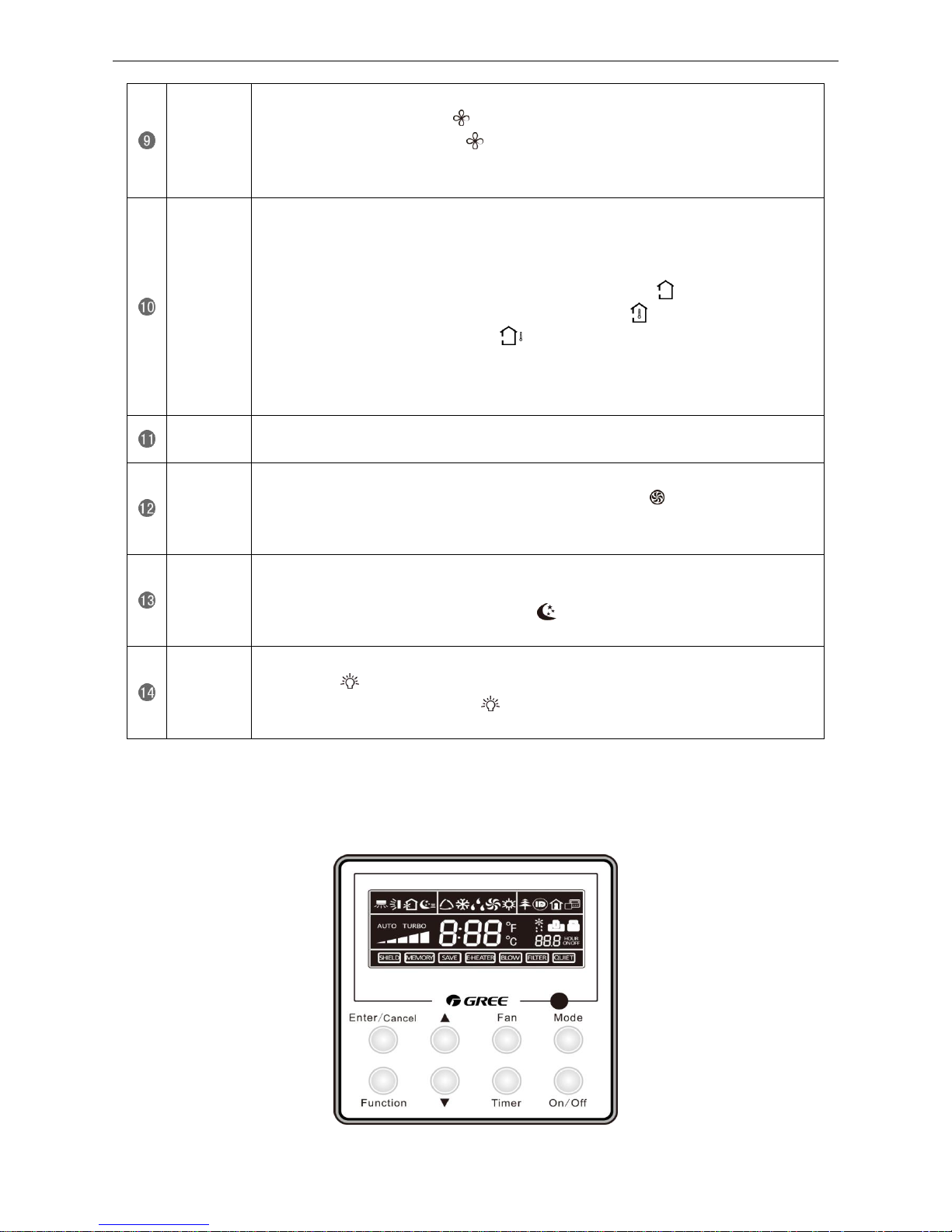
3 WIRED CONTROLLER
3.1 Display View
Figure 2-3-1 Appearance of wired controller
U-Match Series DC Inverter Service Manual
19
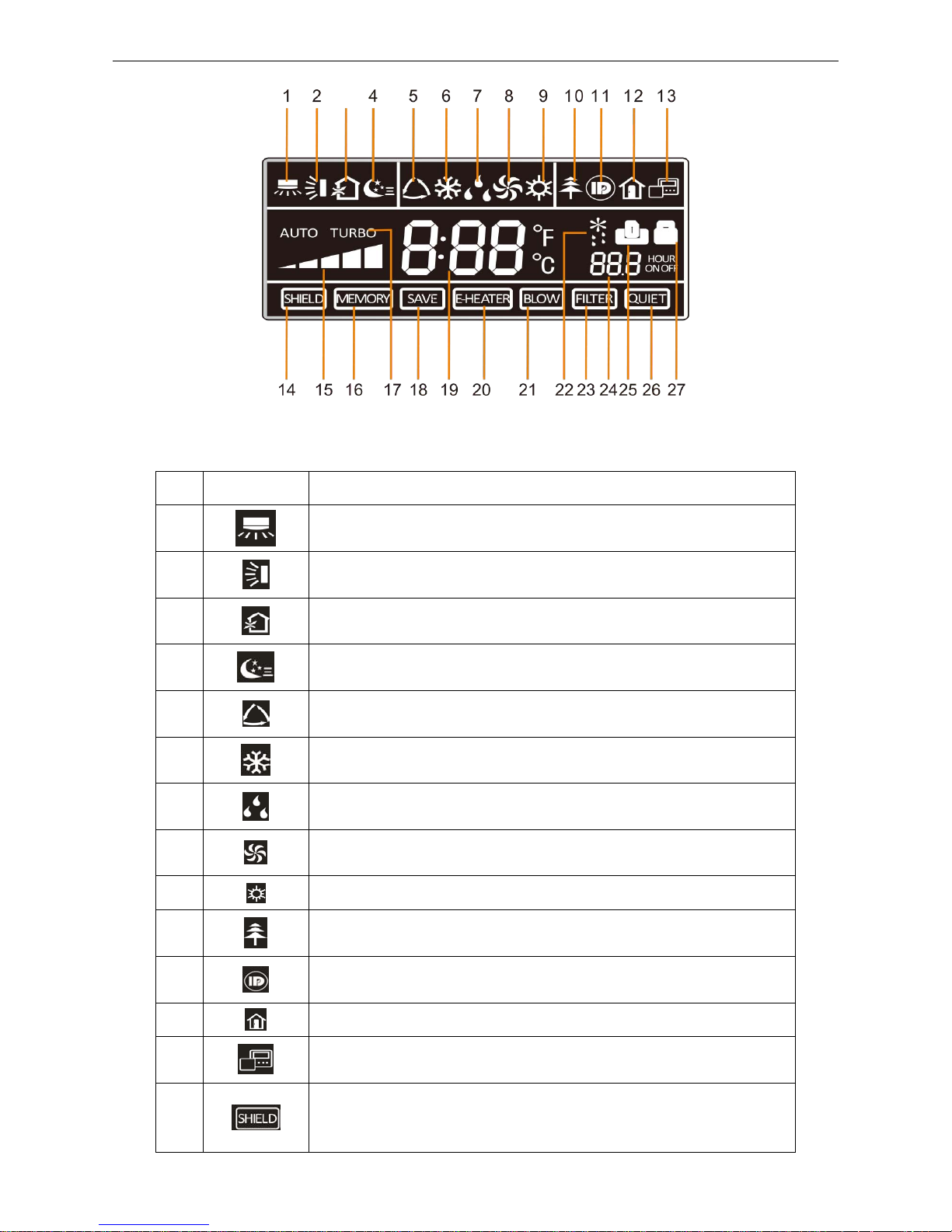
Figure 2-3-2 LCD display of wired controller
Table 2-3-1 Instruction to LCD Display
No.
Icons
Introduction
1 Left and right swing function
2 Up and down swing function
3 Air exchange function
4 Sleep function
5 Auto mode
6 COOL mode 7
DRY mode
8 FAN mode
9 HEAT mode
10 Health function
11 I-Demand function
12 Vacation function
13 Status display of master and slave wired controller
14
Shield function
The button operation, temperature setting, "On/Off" operation, "Mode" setting,
and "Save" setting are disabled.
U-Match Series DC Inverter Service Manual
20
15 Fan speed
16
Memory function
The unit will resume the original setting state after power recovery.
17 Turbo function
18 Energy-saving function
19 Ambient/setting temperature
20 Electric heater
21 Blow function
22 Defrosting function
23 Filter cleaning
24 Timer Setting
25 Keycard control / Detected status sensed by human body
26 Quiet function
27 Lock function
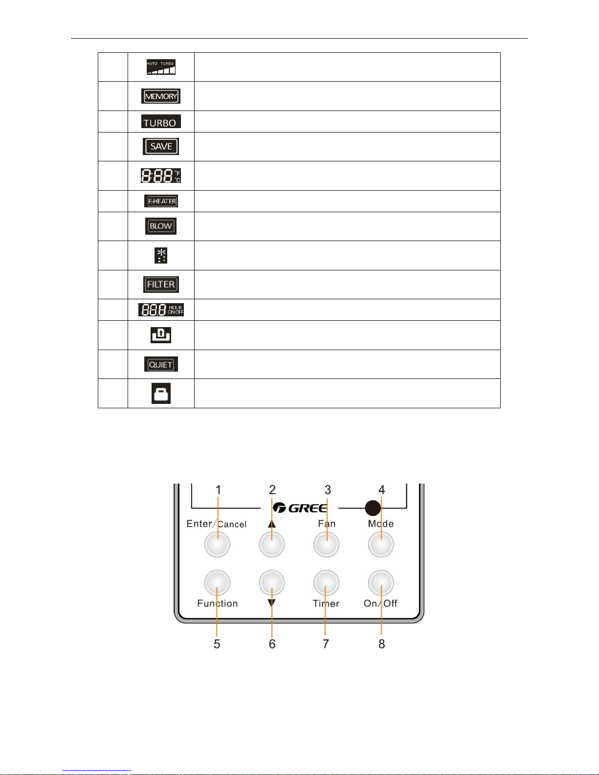
3.2 Operation View
3.2.1 Silk Screen of Buttons
Figure 2-3-3 Silk screen of buttons
U-Match Series DC Inverter Service Manual
21
3.3.2 Instruction to Function of Buttons
Table 2-3-2 Instruction to buttons of wired controller
No.
Description
Functions
1
Enter/Cancel
①. Function selection and canceling;
②. Press it for 5s to view the ambient temperature; press Mode button
to select viewing outdoor ambient temperature or indoor ambient
temperature.
2
▲
①. Running temperature setting range of indoor unit:
16~30℃(61~86℉);
②. Timer setting range: 0.5~24hr;
③. Setting of air function level;
④. Setting of energy-saving temperature;
⑤. Setting of cleaning class.
6
▼
3
Fan
Setting of high/medium high/medium/medium low/low/auto fan speed.
4
Mode
Setting of auto/cooling/heating/fan/dry mode of indoor unit.
5
Function
Switch over among these functions of swing/air/sleep/health/
I-Demand/out/turbo/save/e-heater/X-fan/clean/quiet.
7
Timer
Timer setting.
8
On/Off
Turn on/off indoor unit.
4 Mode
and
2 ▲
Memory function
Press Mode and ▲ buttons at the same time for 5s under off state of the
unit to enter/cancel memory function (If memory function is set, indoor
unit will resume original setting state after power failure and then power
recovery. If not, indoor unit is defaulted to be off after power recovery.
Ex-factory setting of memory function is on).
2 ▲
and
6 ▼
Lock
Upon startup of the unit without malfunction or under off state of the unit,
press ▲ and ▼ buttons at the same time for 5s to enter lock state. In this
case, any other buttons won‟t respond when pressing. Repress ▲ and ▼
buttons for 5s to quit lock state.
4 Mode
and
5 Function
Enquiry and
setting of address
of wired
controller
Under off state of the unit, press Mode and Function buttons at the same
time for 5s to set the address. (More details please refer to project
debugging)
5 Function
and
7 Timer
Setting of project
parameters
(More details
please refer to
the Notes)
Under off state of the unit, press Function and Timer buttons at the same
time for 5s to go to the debugging menu. Press Mode button to adjust the
setting items and press ▲ or ▼ buttons to set the actual value.
4 Mode
and
6 ▼
Switch between
Fahrenheit and
Centigrade
Under off state of the unit, press Mode and ▼ buttons at the same time
for 5s to switch between Fahrenheit and Centigrade.
5 Function
and
6 ▼
Viewing historical
malfunction
Continuously press Function and ▼ buttons for 5s to view historical
malfunction. Then press ▲ and ▼ buttons to adjust displayed content s.
The timer displaying position displays the sequence of malfunction and
the detailed error code. The 5th displayed malfunction is the last
malfunction.
1 Enter/Cancel
and
4 Mode
Setting of master
and slave wired
controller
Under off state of the unit, press Enter/Cancel and Mode buttons at the
same time for 5s to set master and slave wired controller. Press ▲ or ▼
button to adjust. (More details please refer to project debugging)
U-Match Series DC Inverter Service Manual
22
Note:
The following functions can be set through Function and Timer buttons: setting of ambient
temperature sensor, selecting three speeds in high speed and three speeds in low speed of indoor fan
motor, display setting of freeze protection error code, setting of cold air prevention and hot air hot
prevention function, setting of refrigerant-lacking protection function, selecting of blowing residual heat of
indoor unit, selecting of compressor electric heater mode, selecting of low-power consumption mode,
selecting door control function, selecting human sensitive function, long-distance monitoring, temperature
compensation value at the air return port.
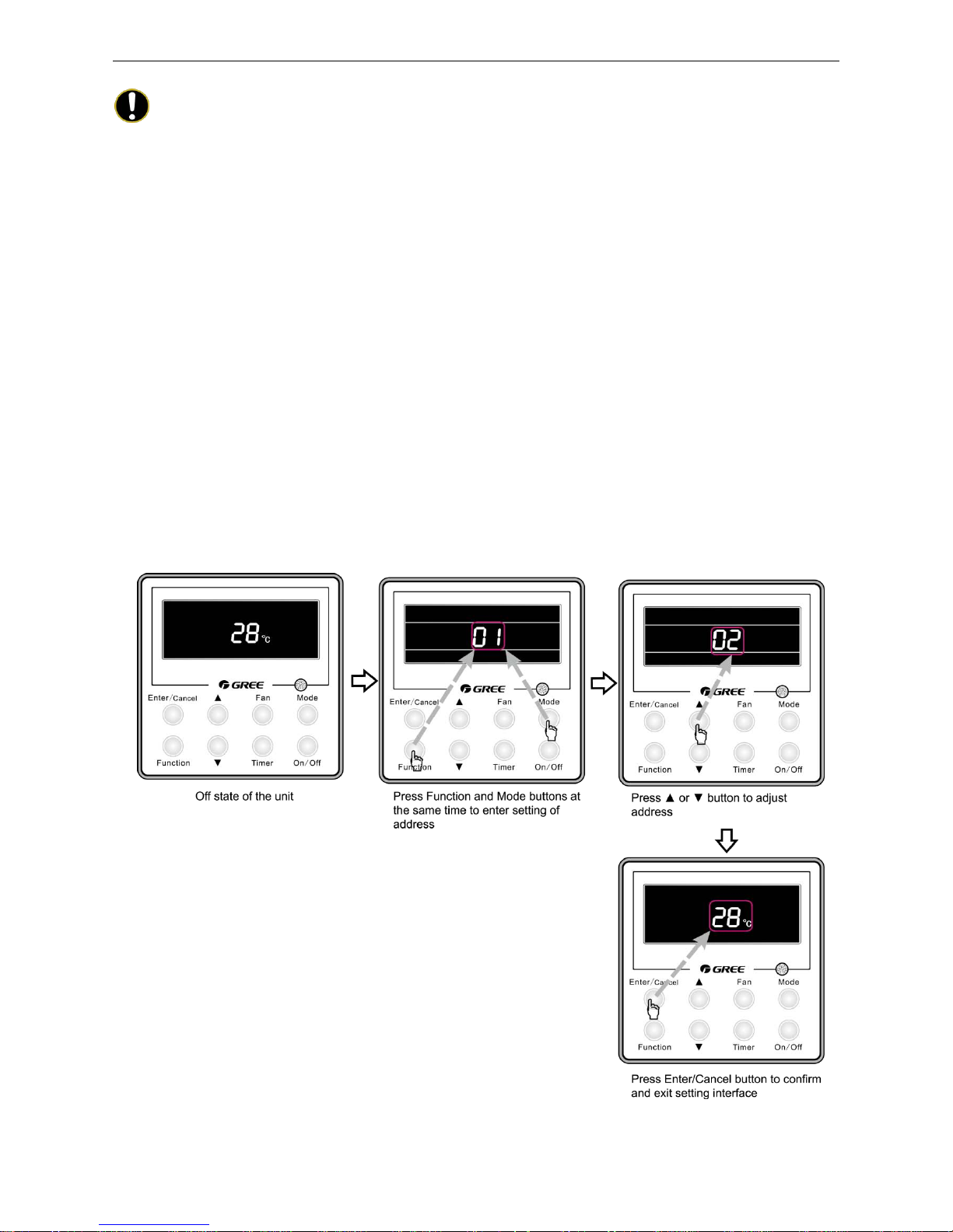
3.2.3 Setting of Wired Controller’s Address
3.2.3.1 Enquiry and Setting of Wired Controller’s Address
Under off state of the unit, press Function and Mode buttons at the same time for 5s to enter setting
interface of wired controller‟s address. In this case, LCD displays address number. Then press▲ or ▼
button to adjust address and then press Enter/Cancel button to confirm. The address setting is related to
the setting of Debugging Function 4.9.10. When the selection in 4.9.10 is 00, address of centralized
controller is to be set and the address setting range is 01~16; when the selection in 4.9.10 is 01, address of
long-distance monitor is to be set and the address setting range is 01~255.
Enquiry and setting of wired controller‟s address is shown as Figure 2-3-4 below:
Figure 2-3-4 Enquiry and setting of wired controller‟s address
U-Match Series DC Inverter Service Manual
23
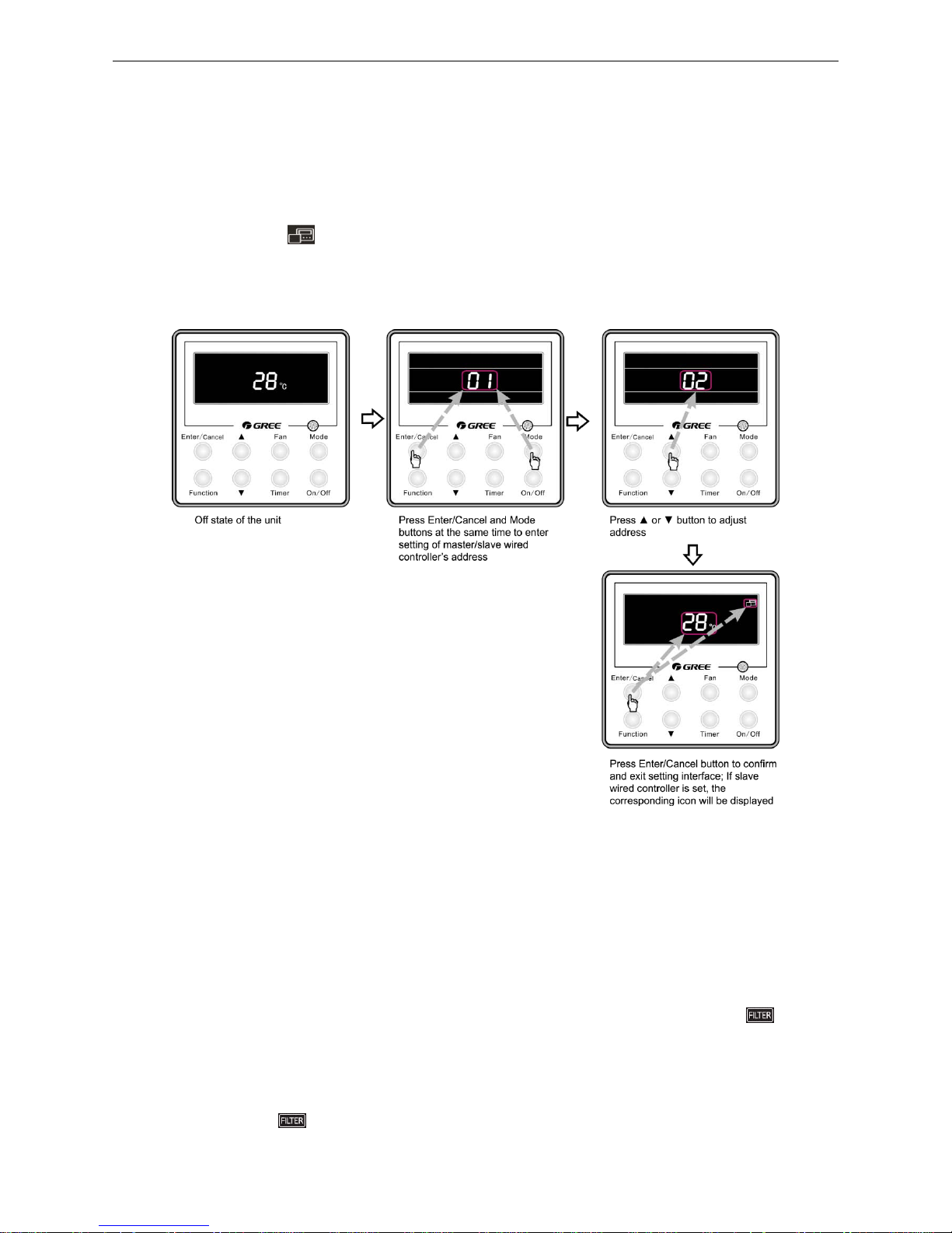
3.2.3.2 Setting of Master/Slave Wired Controller’s Address
Under off status of the unit, press Enter/Cancel and Mode buttons at the same time for 5s to go to the
enquiry and setting interface of master/slave wired controller. In this case, LCD displays wired controller‟s
address (01 for master wired controller and 02 for slave wired controller). Press ▲ or ▼ button to adjust
address of master/slave wired controller and then press Enter/Cancel button to confirm. If slave wired
controller is set, the icon will be displayed.
Note: If there is only one wired controller, it only can be set as the master; if there are two wired
controllers, one should be the master and the other should be the slave.
Setting of master/slave wired controller‟s address is shown as Figure 2-3-5 below:
Figure 2-3-5 Enquiry and setting of master/slave wired controller‟s address
4 OPERATION INSTRUCTION OF SPECIAL
FUNCTIONS
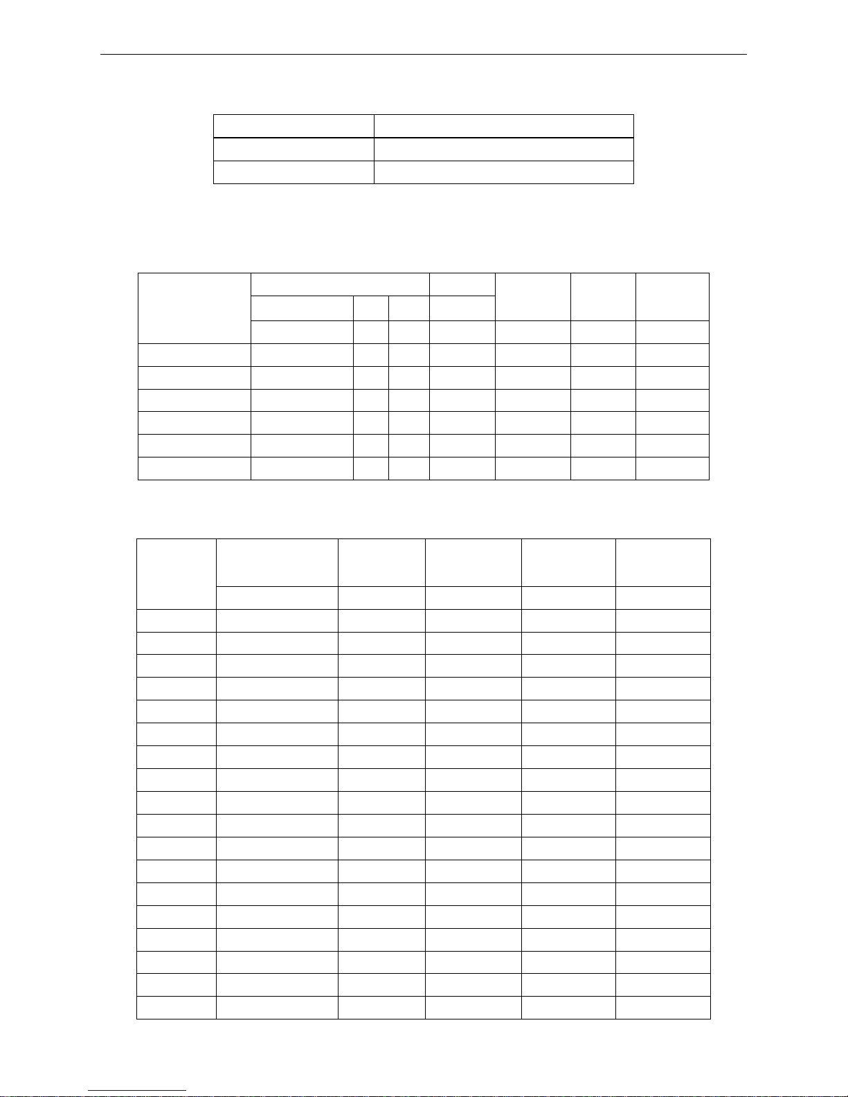
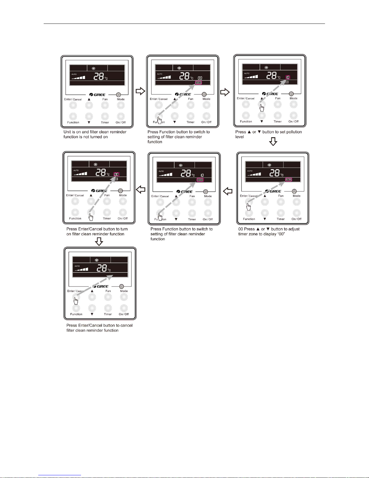
4.1 Setting of Filter Clean Reminder Function
When unit is on, press Function button to switch to filter clean reminder function. The icon will
blink and then enter setting of filter clean reminder function. Timer zone displays the set pollution level and
you can press ▲ or ▼ button to adjust the level. Then press Enter/Cancel button to turn on this function.
When filter clean reminder function is turned on, press Function button to switch to filter clean
reminder function. The icon will blink and press ▲ or ▼ button to adjust timer zone to display “00”.
Then press Enter/Cancel button to cancel this function.
U-Match Series DC Inverter Service Manual
24
Setting of filter clean reminder function is shown as Figure 2-4-1 below:
Figure 2-4-1 Setting of filter clean reminder function
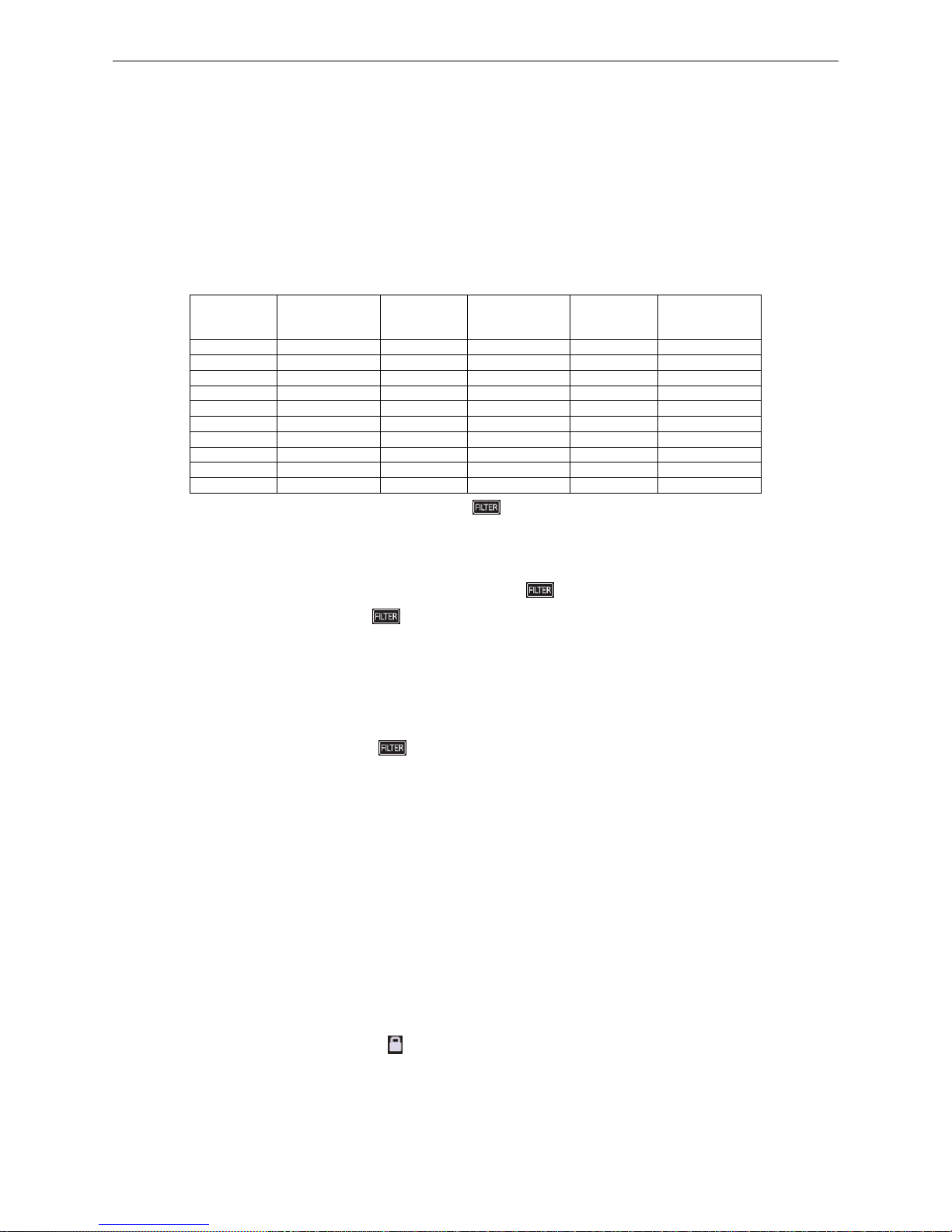
When setting the filter clean reminder function, timer zone will display 2 digits, of which the former
indicates the pollution degree of operating place and the latter indicates the accumulated operating time of
indoor unit. There are 4 types of situations:
(1) Clean Reminder is off (Timer zone shows “00“);
(2) Slight pollution: the former digit in timer zone shows 1 while the latter one shows 0, which
indicates the accumulated operating time is 5500hr. Each time the latter digit increases 1, the
accumulated operating time increases 500hr. When it reaches 9, it means the accumulated
operating time is 10000hr;
(3) Medium pollution: the former digit in timer zone shows 2 while the latter one shows 0, which
indicates the accumulated operating time is 1400hr. Each time the latter digit increases 1, the
U-Match Series DC Inverter Service Manual
25
accumulated operating time increases 400hr. When it reaches 9, it means the accumulated
operating time is 5000hr;
(4) Heavy pollution: the former digit in timer zone shows 3 while the latter one shows 0, which
indicates the accumulated operating time is 100hr. Each time the latter digit increases 1, the
accumulated operating time increases 100hr. When it reaches 9, it means the accumulated
operating time is 1000hr;
The detailed pollution level and the corresponding time is as shown in Table 2-4-1 below:
Table 2-4-1 Pollution level and corresponding time
Pollution
level
Accumulated
operating time
(hour)
Pollution
level
Accumulated
operating time
(hour)
Pollution
level
Accumulated
operating time
(hour)
10
5500
20
1400
30
100
11
6000
21
1800
31
200
12
6500
22
2200
32
300
13
7000
23
2600
33
400
14
7500
24
3000
34
500
15
8000
25
3400
35
600
16
8500
26
3800
36
700
17
9000
27
4200
37
800
18
9500
28
4600
38
900
19
10000
29
5000
39
1000
If filter clean reminder function is turned on, the icon will be on.
(1) If cleaning time is not reached, no mater the setting is changed or not, the accumulated operating
time won‟t be recalculated when pressing Enter/Cancel button;
(2) If cleaning time is reached, in unit on or off state, will blink every 0.5s for reminder. Press
Function button to switch to icon and press ▲ and ▼ button to adjust the level. Then press
Enter/Cancel button, so the accumulated operating time won‟t be cleared (If the adjusted level is
higher than the present accumulated operating time, the icon won‟t blink any more; if the adjusted
level is lower than the present accumulated operating time, the icon will go on blinking).
(3) The only way to cancel filter clean reminder function is to press Function button to switch to filter
clean reminder function. The icon will blink and press ▲ or ▼ button to adjust timer zone to
display “00”. In this case, the accumulated operating time will be cleared.
4.2 Low Temperature Drying Function
Under dry mode and when set temperature is 16℃(61℉), continuously press ▼ button for twice and
then the set temperature will be 12℃ (54℉). In this case, the unit will enter low temperature drying
function.
When low temperature drying function is turned on, press ▲ button or Mode button to exit low
temperature drying function.
4.3 Lock Function
When unit is turned on normally or turned off, pressing ▲ and ▼ buttons at the same time for 5s will
turn on Lock function. LCD will display . Pressing ▲ and ▼ buttons at the same time for 5s to turn off
this function.
When Lock function is turned on, any other buttons won‟t respond when pressing. The function can be
memorized after power failure and then power recovery.
U-Match Series DC Inverter Service Manual
26
4.4 Memory Function
Press Mode and ▲ buttons at the same time for 5s under off state of the unit to turn on or cancel
memory function. If memory function is set, is displayed. If not, indoor unit is defaulted to be off
after power recovery.
If memory function is set, indoor unit will resume original setting state after power failure and then
power recovery.
Note:
If cut off power with 5s after memorized content is changed, the memorized content may be
abnormal. Do not cut off power within 5s after memorized content is changed.
4.5 Door Control Function/Human Sensitive Function
Door control function or human sensitive function can be selected (More details please refer to
Debugging Function). These two functions can‟t be turned on at the same time.
When door control function is selected, the wired controller will work when the room card is inserted
and stop working when the room card is not inserted; when human sensitive function is selected, the wired
controller will work when it senses there is somebody in the room and stop working when it senses there is
nobody in the room. When the door control function senses the room card is not inserted or human
sensitive function senses there is nobody in the room, the wired controller will display icon.
Notes:
① In long-distance monitoring or centralized control, no matter the room card is inserted or not,
the ON/OFF of unit can be controlled. If long-distance monitoring or centralized control
information is received when the room card is not inserted, icon is cleared. When the
card is reinserted, door control function is judged to be turned on. If long-distance monitoring
or centralized control information is received when the room card is inserted, it will keep the
original status.
② The unit can not be controlled by buttons when the card is not inserted.
③ When door control function and human sensitive function have been set at the same time, it
is defaulted that door control function is valid and human sensitive function is invalid.
4.6 Switch between Fahrenheit and Centigrade
Under off state of the unit, press Mode and ▼ buttons at the same time for 5s to switch between
Fahrenheit and Centigrade.
4.7 Enquiry of Ambient Temperature
Under off or on state of the unit, press it for 5s to view the ambient temperature. In this case, timer
zone displays ambient temperature type 01 or 02. Ambient temperature zone displays the corresponding
temperature of that type. 01 stands for outdoor ambient temperature and 02 stands for the indoor ambient
temperature after compensation. Press Mode button to switch between 01 and 02. Pressing other buttons
except Mode button or receiving remote control signal will exit enquiry state. If there is no operation within
20s will also exit enquiry state.

U-Match Series DC Inverter Service Manual
27
Notes:
① If the unit is not connected to outdoor ambient temperature sensor, display of outdoor
ambient temperature will be shielding after energizing for 12hr.
② If there is malfunction of outdoor ambient temperature sensor, display of outdoor ambient
temperature will be shielding after energizing for 12hr.
4.8 Enquiry of Historical Malfunction
Under off or on state of the unit, continuously press Function and ▼ buttons for 5s to view historical
malfunction.
In enquiry state, set temperature displaying zone displays “00”. Press ▲ and ▼ buttons to view the 5
malfunctions happened recently. The timer displaying position displays the detailed error code. The 5th
displayed malfunction is the last malfunction.
4.9 Debugging Function
Under off state of the unit, press Function and Timer buttons at the same time for 5s to go to the
debugging menu. Press Mode button to adjust the setting items and press ▲ or ▼ button to set the actual
value.
4.9.1 Setting ambient temperature sensor (dual ambient temperature
sensors function)
Under debugging state, press Mode button to adjust to “00” in temperature displaying zone. Timer
zone displays setting state and press ▲ or ▼ button to adjust. There are 3 selections:
(1) The ambient temperature at air return is set as indoor ambient temperature (timer zone displays
01).
(2) The temperature at wired controller is set as indoor ambient temperature (timer zone displays 02).
(3) Select the temperature sensor at air return in cooling, dry and fan mode; select the temperature
sensor at wired controller in heating and auto mode.
4.9.2 Selecting three speeds in high speed and three speeds in low speed
of indoor fan motor
Under debugging state, press Mode button to adjust to “01” in temperature displaying zone. Timer
zone displays setting state and press ▲ or ▼ button to adjust. There are 2 selections:
(1) Three speeds in low speed (LCD displays 01)
(2) Three speeds in high speed (LCD displays 02)
Three speeds in low speed include high, medium and low speeds; three speeds in high speed include
super high, high and medium speed.
Note:
For this series, this function is invalid.
 Loading...