

Gree GEH09AA-K3DNA1B, GEH09AA-K3DNA1C, GEH12AA-K3DNA1B, GEH12AA-K3DNA1C, GEH18AA-K3DNA1B Service Manual
...
GREE ELECTRIC APPLIANCES,INC.OF ZHUHAI
Change for Life
Service Manual
Models: GEH09AA-K3DNA1B
GEH09AA-K3DNA1C
GEH12AA-K3DNA1B
GEH12AA-K3DNA1C
GEH18AA-K3DNA1B
GEH18AA-K3DNA1C
(Refrigerant R410A)

Service Manual
Table of Contents
Table of Contents
Part
Ⅰ
: Technical Information
.........................................................................1
1. Summary
........................................................................................................................1
2. Specications
............................................................................................................2
2.1 Specication Sheet .............................................................................................................2
2.2 Operation Characteristic Curve ..........................................................................................8
2.3 Capacity Variation Ratio According to Temperature ...........................................................9
2.4 Cooling and Heating Data Sheet in Rated Frequency .....................................................10
2.5 Noise Curve ......................................................................................................................10
3. Outline Dimension Diagram
.........................................................................................12
3.1 Indoor Unit ........................................................................................................................12
3.2 Outdoor Unit .....................................................................................................................13
4. Refrigerant System Diagram
......................................................................15
5. Electrical Part
...........................................................................................................16
5.1 Wiring Diagram .................................................................................................................16
5.2 PCB Printed Diagram .......................................................................................................19
6. Function and Control
........................................................................................24
6.1 Remote Controller Introduction .......................................................................................24
6.2 Brief Description of Modes and Functions ........................................................................28
Part
Ⅱ
: Installation and Maintenance
...................................................30
7. Notes for Installation and Maintenance
............................................30
8. Installation
..................................................................................................................32
8.1 Choosing an Installation Site ............................................................................................32
8.2 Indoor Unit Installation Drawings ......................................................................................32
8.3 Installation Tips .................................................................................................................34
8.4 Indoor Unit Installation ......................................................................................................34
8.5 Outdoor Unit Installation ...................................................................................................39
8.6 Vacuum Pumping and Leak Detection .............................................................................40
8.7 Check after Installation and Test Operation .....................................................................41

Service Manual
9. Maintenance
............................................................................................................42
9.1 Error Code List ...............................................................................................................42
9.2 Troubleshooting for Main Malfunction ............................................................................44
9.3 Maintenance Method for Normal Malfunction .................................................................49
10. Exploded View and Parts List
..............................................................51
10.1 Indoor Unit ....................................................................................................................51
10.2 Outdoor Unit .................................................................................................................54
11. Removal Procedure
.......................................................................................60
11.1 Removal Procedure of Indoor Unit ...............................................................................60
11.2 Removal Procedure of Outdoor Unit ............................................................................64
Appendix:
........................................................................................................................76
Appendix 1: Reference Sheet of Celsius and Fahrenheit ....................................................76
Appendix 2: Conguration of Connection Pipe .....................................................................76
Appendix 3: Pipe Expanding Method ...................................................................................77
Appendix 4: List of Resistance for Temperature Sensor ......................................................78
1
Technical Information
Service Manual
1. Summary
Part
Ⅰ
: Technical Information
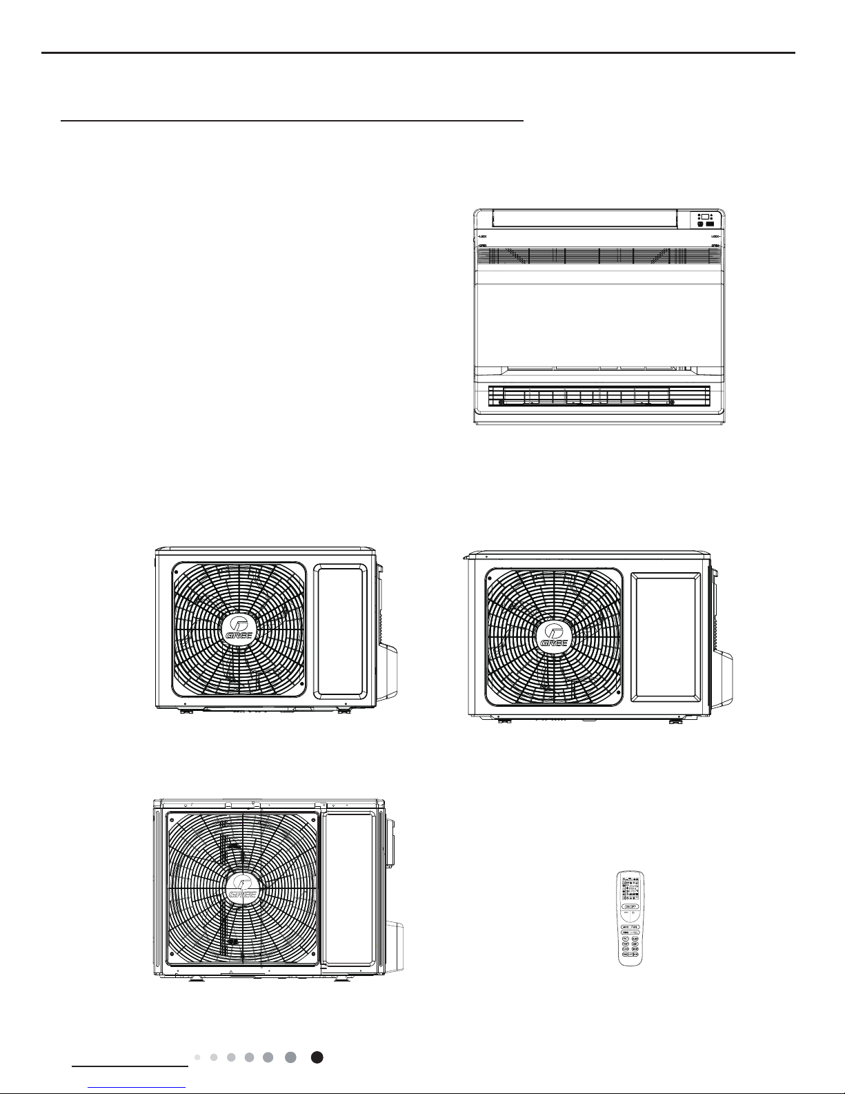
Indoor Unit
Outdoor Unit
GEH09AA-K3DNA1B/O
GEH09AA-K3DNA1C/O
GEH12AA-K3DNA1B/O
GEH12AA-K3DNA1C/O
GEH18AA-K3DNA1B/O
GEH18AA-K3DNA1C/O
GEH09AA-K3DNA1B/I
GEH09AA-K3DNA1C/I
GEH12AA-K3DNA1B/I
GEH12AA-K3DNA1C/I
GEH18AA-K3DNA1B/I
GEH18AA-K3DNA1C/I
Remote Controller
YAA1FB1
2
Technical Information
Service Manual
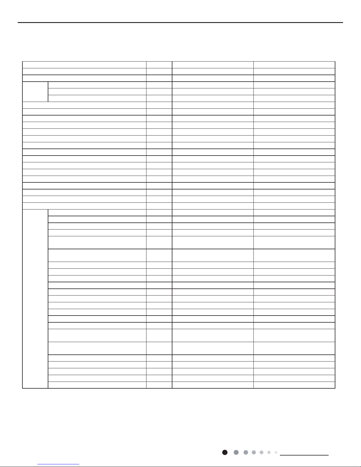
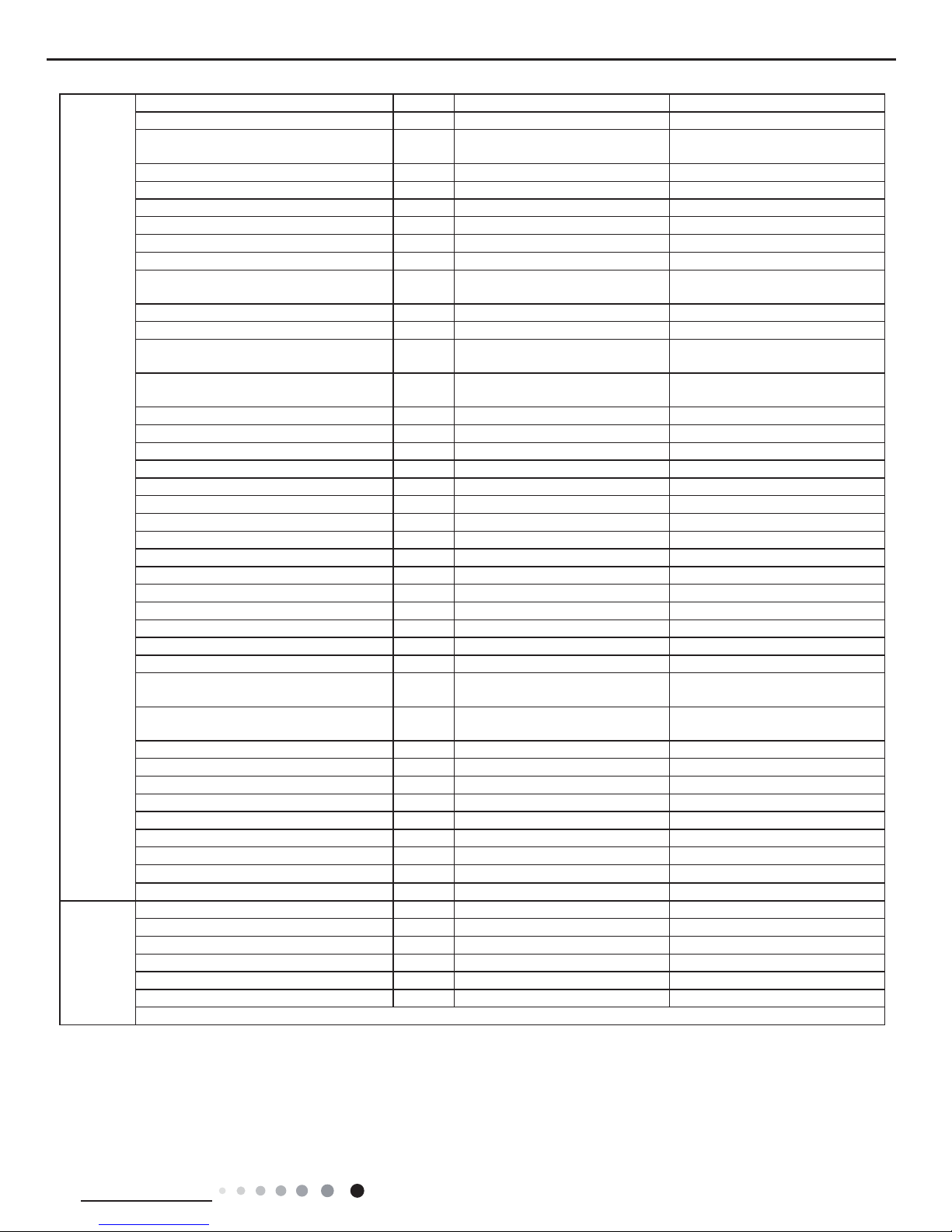
2. Specications
2.1 Specication Sheet
Parameter Unit Value
Model GEH09AA-K3DNA1B GEH09AA-K3DNA1C
Product Code CV010001200 CV010002000
Power
Supply
Rated Voltage V
~
220-240 220-240
Rated Frequency Hz 50 50
Phases 1 1
Power Supply Mode Indoor Indoor
Cooling Capacity(Min~Max) W 2600(450~3200) 2600(450~3200)
Heating Capacity(Min~Max) W 2750(450~3750) 2750(450~3750)
Cooling Power Input(Min~Max) W 720(200~1200) 720(200~1200)
Heating Power Input(Min~Max) W 720(200~1550) 740(200~1550)
Cooling Current Input A 3.2 3.1
Heating Current Input A 3.2 3.3
Rated Input W 1550 1550
Rated Current A 5.3 5.3
Air Flow Volume(SH/H/HM/M/LM/L/SL) m3/h 500/430/410/370/330/280/250 500/430/410/370/330/280/250
Dehumidifying Volume L/h 0.8 0.8
EER W/W 3.61 3.71
COP W/W 3.82 3.72
SEER W/W 6.1 6.5
HSPF W/W / /
Application Area m
2
12-18 12-18
Indoor
Unit
Indoor Unit Model GEH09AA-K3DNA1B/I GEH09AA-K3DNA1C/I
Indoor Unit Product Code CV010N01200 CV010N02000
Fan Type Centrifugal Centrifugal
Fan Diameter Length(DXL) mm Φ80X370 Φ80X370
Cooling Speed
(SH/H/HM/M/LM/L/SL)
r/min 650/560/530/480/430/370/320 650/560/530/480/430/370/320
Heating Speed
(SH/H/HM/M/LM/L/SL)
r/min 650/560/530/480/430/370/320 650/560/530/480/430/370/320
Fan Motor Power Output W 30 30
Fan Motor RLA A 0.15 0.15
Fan Motor Capacitor μF / /
Evaporator Form Aluminum Fin-copper Tube Aluminum Fin-copper Tube
Evaporator Pipe Diameter mm Φ6.35 Φ7
Evaporator Row-n Gap mm 2-1.2 2-1.3
Evaporator Coil Length (LXDXW) mm 511X24X396 511X25.4X400
Swing Motor Model MP24EB/MP24AE MP24EB/MP24AE
Swing Motor Power Output W 1/1 1.5/1.5
Fuse Current A 3.15 3.15
Sound Pressure Level
(SH/H/HM/M/LM/L/SL)
dB (A) 40/38/36/33/30/26/24 40/38/36/33/30/26/24
Sound Power Level
(SH/H/HM/M/LM/L/SL)
dB (A) 50/48/46/43/40/36/34 50/48/46/43/40/36/34
Dimension (WXHXD) mm 700X600X215 700X600X215
Dimension of Carton Box (LXWXH) mm 785X682X280 785X682X280
Dimension of Package(LXWXH) mm 788X697X283 788X697X283
Net Weight kg 15 15
Gross Weight kg 18 18
3
Technical Information
Service Manual
The above data is subject to change without notice. Please refer to the nameplate of the unit.
Outdoor
Unit
Outdoor Unit Model GEH09AA-K3DNA1B/O GEH09AA-K3DNA1C/O
Outdoor Unit Product Code CV010W01200 CV010W02000
Compressor Manufacturer
ZHUHAI LANDA COMPRESSOR
CO.,LTD
ZHUHAI GREE DAIKIN DEVICE
CO.,LTD
Compressor Model QXA-A086zE190A 1GDY23AXD
Compressor Oil FVC 68D or RB 68EP DAPHNE FVC50K
Compressor Type Rotary Rotary
Compressor LRA. A 20 16.5
Compressor RLA A 4.5 4
Compressor Power Input W 780 845
Compressor Overload Protector
1NT11L-6233 or KSD115ºC or
HPC115/95U1
KSD115ºC or HPC115/95
Throttling Method Electron expansion valve Electron expansion valve
Set Temperature Range ºC 16~30 16~30
Cooling Operation Ambient Temperature
Range
ºC 18~43 -15~43
Heating Operation Ambient Temperature
Range
ºC -15~24 -20~24
Condenser Form Aluminum Fin-copper Tube Aluminum Fin-copper Tube
Condenser Pipe Diameter mm Φ7 Φ7
Condenser Rows-n Gap mm 2-1.4 2-1.4
Condenser Coil Length (LXDXW) mm 506X38.1X679 506X38.1X679
Fan Motor Speed rpm 900 900
Fan Motor Power Output W 30 30
Fan Motor RLA A 0.24 0.36
Fan Motor Capacitor μF / /
Outdoor Unit Air Flow Volume m3/h 1600 1600
Fan Type Axial-ow Axial-ow
Fan Diameter mm Φ400 Φ400
Defrosting Method Automatic Defrosting Automatic Defrosting
Climate Type T1 T1
Isolation I I
Moisture Protection IP24 IP24
Permissible Excessive Operating Pressure
for the Discharge Side
MPa 4.3 4.3
Permissible Excessive Operating Pressure
for the Suction Side
MPa 2.5 2.5
Sound Pressure Level (H/M/L) dB (A) 50/-/- 52/-/-
Sound Power Level (H/M/L) dB (A) 61/-/- 62/-/-
Dimension(WXHXD) mm 776X540X320 776X540X320
Dimension of Carton Box (LXWXH) mm 848X360X580 848X360X580
Dimension of Package(LXWXH) mm 851X363X595 851X363X595
Net Weight kg 31 32
Gross Weight kg 33.5 34.5
Refrigerant R410A R410A
Refrigerant Charge kg 0.9 0.9
Connection
Pipe
Connection Pipe Length m 5 5
Connection Pipe Gas Additional Charge g/m 20 20
Outer Diameter Liquid Pipe mm Φ6 Φ6
Outer Diameter Gas Pipe mm Φ9.52 Φ9.52
Max Distance Height m 10 10
Max Distance Length m 15 15
Note: The connection pipe applies metric diameter.
4
Technical Information
Service Manual
Parameter Unit Value Value
Model GEH12AA-K3DNA1B GEH12AA-K3DNA1C
Product Code CV010001300 CV010001900
Power
Supply
Rated Voltage V
~
220-240 220-240
Rated Frequency Hz 50 50
Phases 1 1
Power Supply Mode Indoor Indoor
Cooling Capacity(Min~Max) W 3500(600~3950) 3500(600~3950)
Heating Capacity(Min~Max) W 3650(600~4700) 3650(600~4700)
Cooling Power Input(Min~Max) W 1100(220~1400) 1100(220~1400)
Heating Power Input(Min~Max) W 1100(220~1580) 1000(220~1580)
Cooling Current Input A 4.9 4.9
Heating Current Input A 4.9 4.4
Rated Input W 1580 1580
Rated Current A 6.2 6.2
Air Flow Volume(SH/H/HM/M/LM/L/SL) m3/h 600/520/480/440/400/360/280 600/520/480/440/400/360/280
Dehumidifying Volume L/h 1.2 1.2
EER W/W 3.18 3.18
COP W/W 3.32 3.65
SEER W/W 6.1 6.3
HSPF W/W / /
Application Area m
2
16-24 16-24
Indoor
Unit
Indoor Unit Model GEH12AA-K3DNA1B/I GEH12AA-K3DNA1C/I
Indoor Unit Product Code CV010N01300 CV010N01900
Fan Type Centrifugal Centrifugal
Fan Diameter Length(DXL) mm Φ80X370 Φ80X370
Cooling Speed
(SH/H/HM/M/LM/L/SL)
r/min 750/650/600/550/500/450/350 750/650/600/550/500/450/350
Heating Speed
(SH/H/HM/M/LM/L/SL)
r/min 750/650/600/550/500/450/350 750/650/600/550/500/450/350
Fan Motor Power Output W 30 30
Fan Motor RLA A 0.15 0.15
Fan Motor Capacitor μF / /
Evaporator Form Aluminum Fin-copper Tube Aluminum Fin-copper Tube
Evaporator Pipe Diameter mm Φ6.35 Φ7
Evaporator Row-n Gap mm 2-1.2 2-1.3
Evaporator Coil Length (LXDXW) mm 511X24X396 511X25.4X400
Swing Motor Model MP24EB/MP24AE MP24EB/MP24AE
Swing Motor Power Output W 1/1 1.5/1.5
Fuse Current A 3.15 3.15
Sound Pressure Level
(SH/H/HM/M/LM/L/SL)
dB (A) 42/40/38/37/35/32/26 42/40/38/37/35/32/26
Sound Power Level
(SH/H/HM/M/LM/L/SL)
dB (A) 52/50/48/47/45/42/36 52/50/48/47/45/42/36
Dimension (WXHXD) mm 700X600X215 700X600X215
Dimension of Carton Box (LXWXH) mm 785X682X280 785X682X280
Dimension of Package(LXWXH) mm 788X697X283 788X697X283
Net Weight kg 15 15
Gross Weight kg 18 18
5
Technical Information
Service Manual
The above data is subject to change without notice. Please refer to the nameplate of the unit.
Outdoor
Unit
Outdoor Unit Model GEH12AA-K3DNA1B/O GEH12AA-K3DNA1C/O
Outdoor Unit Product Code CV010W01300 CV010W01900
Compressor Manufacturer
ZHUHAI LANDA COMPRESSOR
CO.,LTD
ZHUHAI GREE DAIKIN DEVICE
CO.,LTD
Compressor Model QXA-A091zE190A 1GDY23AXD
Compressor Oil FVC 68D or RB 68EP DAPHNE FVC50K
Compressor Type Rotary Rotary
Compressor LRA. A 20 16.5
Compressor RLA A 4.5 4
Compressor Power Input W 780 845
Compressor Overload Protector
1NT11L-6233 or KSD115ºC or
HPC115/95U1
KSD115ºC or HPC115/95
Throttling Method Electron expansion valve Electron expansion valve
Set Temperature Range ºC 16~30 16~30
Cooling Operation Ambient Temperature
Range
ºC 18~43 -15~43
Heating Operation Ambient Temperature
Range
ºC -15~24 -20~24
Condenser Form Aluminum Fin-copper Tube Aluminum Fin-copper Tube
Condenser Pipe Diameter mm Φ9.52 Φ9.52
Condenser Rows-n Gap mm 2-1.4 2-1.4
Condenser Coil Length (LXDXW) mm 512X44X741 512X44X741
Fan Motor Speed rpm 900 900
Fan Motor Power Output W 30 30
Fan Motor RLA A 0.24 0.36
Fan Motor Capacitor μF / /
Outdoor Unit Air Flow Volume m3/h 1800 1800
Fan Type Axial-ow Axial-ow
Fan Diameter mm Φ400 Φ400
Defrosting Method Automatic Defrosting Automatic Defrosting
Climate Type T1 T1
Isolation I I
Moisture Protection IP24 IP24
Permissible Excessive Operating Pressure
for the Discharge Side
MPa 4.3 4.3
Permissible Excessive Operating Pressure
for the Suction Side
MPa 2.5 2.5
Sound Pressure Level (H/M/L) dB (A) 54/-/- 54/-/-
Sound Power Level (H/M/L) dB (A) 63/-/- 63/-/-
Dimension(WXHXD) mm 848X540X320 848X540X320
Dimension of Carton Box (LXWXH) mm 878X360X580 878X360X580
Dimension of Package(LXWXH) mm 881X363X595 881X363X595
Net Weight kg 33 34
Gross Weight kg 35.5 36.5
Refrigerant R410A R410A
Refrigerant Charge kg 1.15 1.15
Connection
Pipe
Connection Pipe Length m 5 5
Connection Pipe Gas Additional Charge g/m 20 20
Outer Diameter Liquid Pipe mm Φ6 Φ6
Outer Diameter Gas Pipe mm Φ9.52 Φ9.52
Max Distance Height m 10 10
Max Distance Length m 20 20
Note: The connection pipe applies metric diameter.
6
Technical Information
Service Manual
Parameter Unit Value Value
Model GEH18AA-K3DNA1B GEH18AA-K3DNA1C
Product Code CV010001400 CV010001800
Power
Supply
Rated Voltage V
~
220-240 220-240
Rated Frequency Hz 50 50
Phases 1 1
Power Supply Mode Indoor Indoor
Cooling Capacity(Min~Max) W 5200(1260~6600) 5200(1260~6600)
Heating Capacity(Min~Max) W 5500(1120~6800) 5500(1120~6800)
Cooling Power Input(Min~Max) W 1760(380~2450) 1650(380~2450)
Heating Power Input(Min~Max) W 1600(350~2500) 1550(350~2500)
Cooling Current Input A 7.8 7.3
Heating Current Input A 7.1 6.9
Rated Input W 2500 2500
Rated Current A 10.9 10.9
Air Flow Volume(SH/H/HM/M/LM/L/SL) m3/h 650/620/550/500/450/410/320 700/650/580/520/460/410/320
Dehumidifying Volume L/h 1.8 1.8
EER W/W 2.95 3.15
COP W/W 3.44 3.55
SEER W/W 5.6 5.8
HSPF W/W / /
Application Area m
2
23-34 23-34
Indoor
Unit
Indoor Unit Model GEH18AA-K3DNA1B/I GEH18AA-K3DNA1C/I
Indoor Unit Product Code CV010N01400 CV010N01800
Fan Type Centrifugal Centrifugal
Fan Diameter Length(DXL) mm Φ80X370 Φ80X370
Cooling Speed
(SH/H/HM/M/LM/L/SL)
r/min 840/800/720/650/580/530/410 840/800/720/650/580/530/410
Heating Speed
(SH/H/HM/M/LM/L/SL)
r/min 930/840/760/690/620/570/450 930/840/760/690/620/570/450
Fan Motor Power Output W 30 30
Fan Motor RLA A 0.15 0.15
Fan Motor Capacitor μF / /
Evaporator Form Aluminum Fin-copper Tube Aluminum Fin-copper Tube
Evaporator Pipe Diameter mm Φ6.35 Φ7
Evaporator Row-n Gap mm 2-1.2 2-1.3
Evaporator Coil Length (LXDXW) mm 511X24X396 511X25.4X400
Swing Motor Model MP24EB/MP24AE MP24EB/MP24AE
Swing Motor Power Output W 1.5/1.5 1.5/1.5
Fuse Current A 3.15 3.15
Sound Pressure Level
(SH/H/HM/M/LM/L/SL)
dB (A) 48/46/44/41/38/36/32 48/46/44/41/38/36/32
Sound Power Level(SH/H/HM/M/LM/L/SL) dB (A) 58/56/54/51/48/46/42 58/56/54/51/48/46/42
Dimension (WXHXD) mm 700X215X600 700X215X600
Dimension of Carton Box (LXWXH) mm 785X280X682 785X280X682
Dimension of Package(LXWXH) mm 788X283X697 788X283X697
Net Weight kg 15 15
Gross Weight kg 18 18
7
Technical Information
Service Manual
Outdoor
Unit
Outdoor Unit Model GEH18AA-K3DNA1B/O GEH18AA-K3DNA1C/O
Outdoor Unit Product Code CV010W01400 CV010W01800
Compressor Manufacturer
ZHUHAI LANDA COMPRESSOR
CO.,LTD
ZHUHAI LANDA COMPRESSOR
CO.,LTD
Compressor Model QXA-B141zF030A QXA-B141zF030
Compressor Oil 68EP 68EP
Compressor Type Rotary Rotary
Compressor LRA. A 25 18
Compressor RLA A 7.2 7.2
Compressor Power Input W 1440 1440
Compressor Overload Protector
1NT11L-6233 or KSD115ºC or
HPC115/95U1
1N T11L-6 233 o r KSD 115 ºC or
HPC115/95U1
Throttling Method Electron expansion valve Electron expansion valve
Set Temperature Range ºC 16~30 16~30
Cooling Operation Ambient Temperature
Range
ºC 18~43 -15~43
Heating Operation Ambient Temperature
Range
ºC -15~24 -20~24
Condenser Form Aluminum Fin-copper Tube Aluminum Fin-copper Tube
Condenser Pipe Diameter mm Φ7 Φ7
Condenser Rows-n Gap mm 2-1.4 2-1.4
Condenser Coil Length (LXDXW) mm 851X38.1X660 851X38.1X660
Fan Motor Speed rpm 800 800
Fan Motor Power Output W 60 60
Fan Motor RLA A 0.28 0.39
Fan Motor Capacitor μF / /
Outdoor Unit Air Flow Volume m3/h 3200 3200
Fan Type Axial-ow Axial-ow
Fan Diameter mm Φ520 Φ520
Defrosting Method Automatic Defrosting Automatic Defrosting
Climate Type T1 T1
Isolation I I
Moisture Protection IP24 IP24
Permissible Excessive Operating Pressure
for the Discharge Side
MPa 4.3 4.3
Permissible Excessive Operating Pressure
for the Suction Side
MPa 2.5 2.5
Sound Pressure Level (H/M/L) dB (A) 56/-/- 55/-/-
Sound Power Level (H/M/L) dB (A) 63/-/- 65/-/-
Dimension(WXHXD) mm 963X700X396 963X700X396
Dimension of Carton Box (LXWXH) mm 1026X455X735 1026X455X735
Dimension of Package(LXWXH) mm 1029X458X750 1029X458X750
Net Weight kg 46 45
Gross Weight kg 51 49.5
Refrigerant R410A R410A
Refrigerant Charge kg 1.3 1.3
Connection
Pipe
Connection Pipe Length m 5 5
Connection Pipe Gas Additional Charge g/m 20 20
Outer Diameter Liquid Pipe mm Φ6 Φ6
Outer Diameter Gas Pipe mm Φ12 Φ12
Max Distance Height m 10 10
Max Distance Length m 25 25
Note: The connection pipe applies metric diameter.
The above data is subject to change without notice. Please refer to the nameplate of the unit.
8
Technical Information
Service Manual
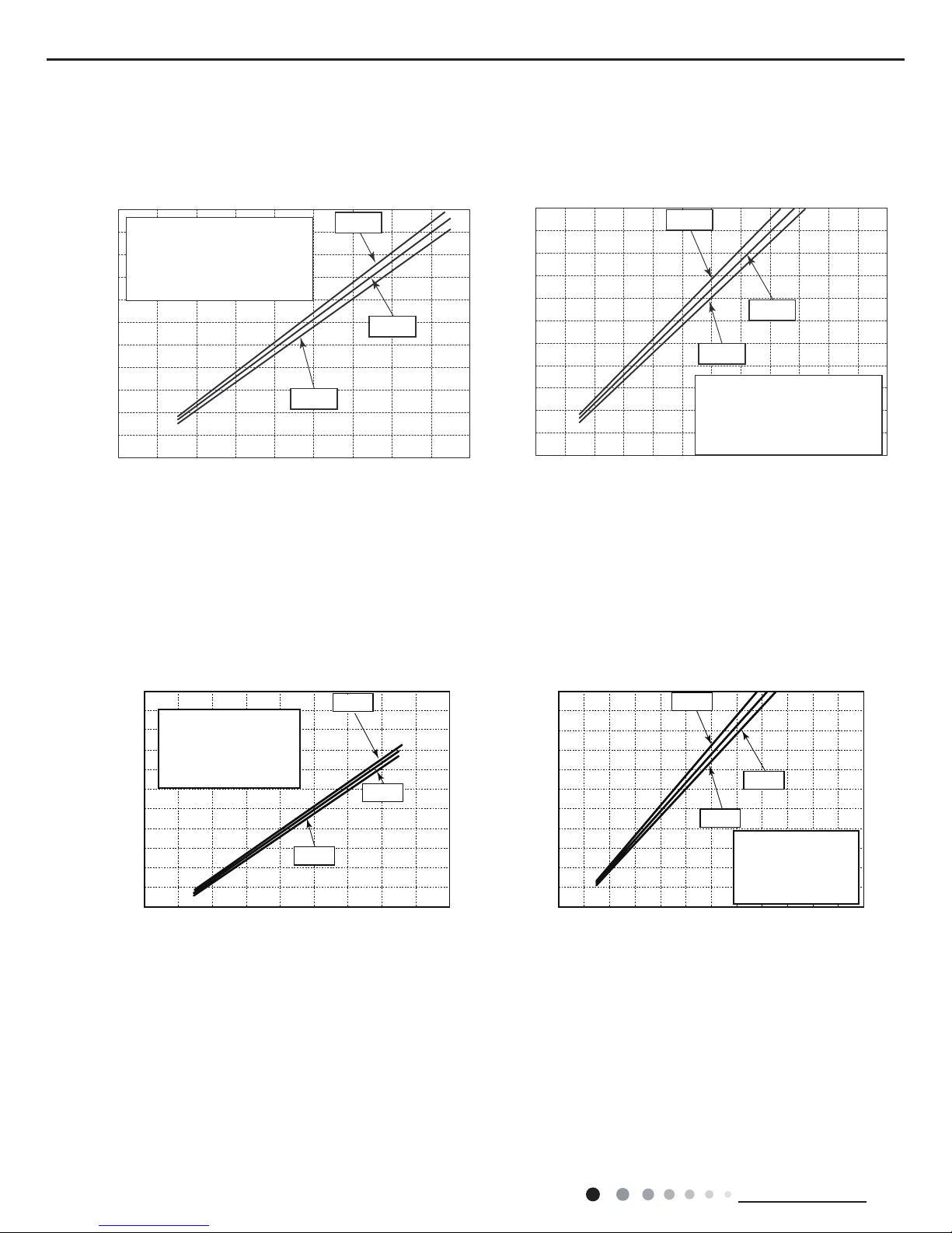
2.2 Operation Characteristic Curve
Cooling
Cooling
09K 12K
18K
Heating
Heating
0
09070605040302010
11 0210010908070605040302010
80
11
10
9
8
7
6
5
4
3
2
1
0
11
10
9
8
7
6
5
4
3
2
1
0
• Conditions
Indoor : DB27˚C/WB19˚C
Outdoor : DB35˚C/WB24˚C
Indoor air flow : High
Pipe length : 5m
• Conditions
Indoor : DB20˚C/WB15˚C
Outdoor : DB7˚C/WB6˚C
Indoor air flow : High
Pipe length : 5m
220V
230V
240V
220V
230V
240V
Current (A)
Current (A)
Compressor frequency(Hz)
Compressor frequency(Hz)
Cooling Heating
0 10 20 30 40 50 60 70 90 0 10 20 30 40 50 60 70 80 90 100 120 110
80
11
10
9
8
7
6
5
4
3
2
1
0
Compressor speed (rps)
) A ( t n e r r u C
11
10
9
8
7
6
5
4
3
2
1
0
Compressor speed (rps)
) A ( t n e r r u C
220V
230V
240V
220V
230V
240V
• Conditions
Indoor: DB27°C/WB19°C
Outdoor: DB35°C/WB24°C
Indoor air flow: High
Pipe length: 5m
• Conditions
Indoor: DB20°C/WB15°C
Outdoor: DB7°C/WB6°C
Indoor air flow: High
Pipe length: 5m
9
Technical Information
Service Manual
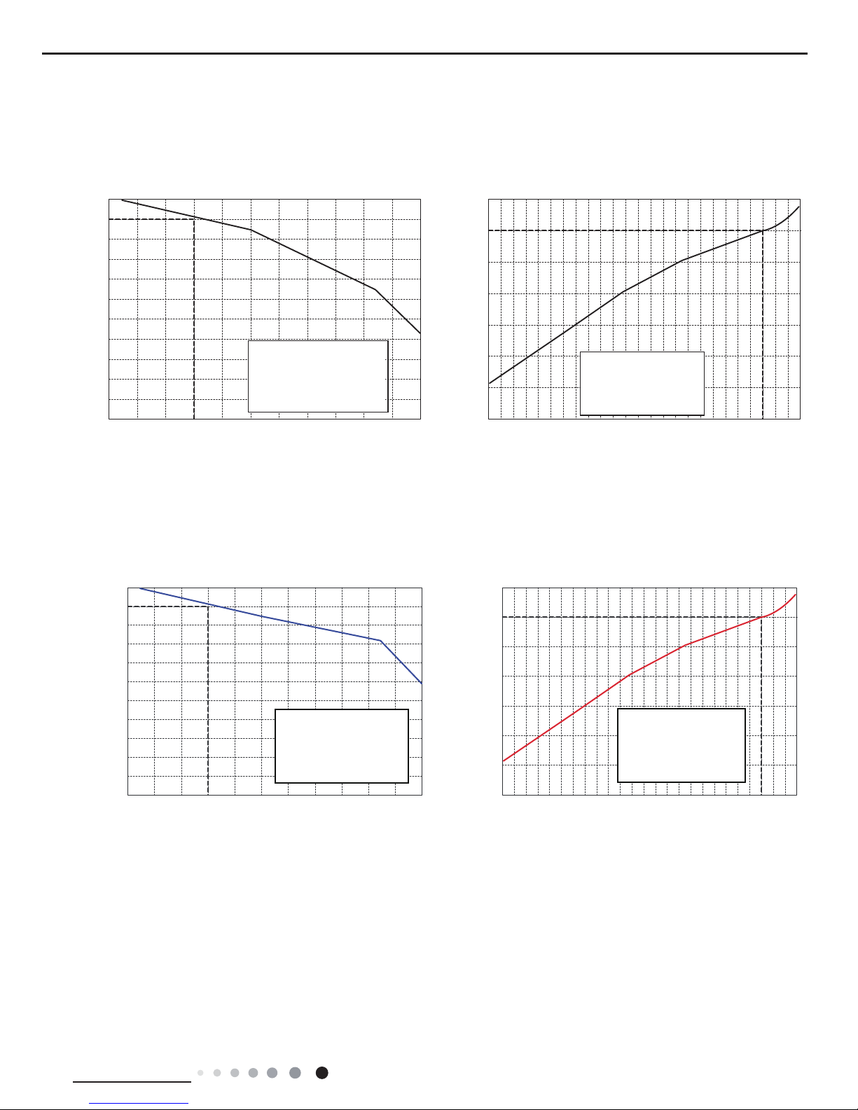
2.3 Capacity Variation Ratio According to Temperature
09K 12K
18K
Cooling
Cooling
Heating
Heating
32 33 34 35 36 37 38 39 43 –15 –10 –5 0 5 7 10
40 41 42
100
105
95
90
85
80
75
70
65
60
55
50
Outdoor temp. (˚C)
110
100
90
80
70
60
50
40
Outdoor temp. (˚C)
Capacity ratio (%)
Capacity ratio (%)
• Conditions
Indoor: DB27°C/WB19°C
Outdoor: DB35°C/WB24°C
Indoor air flow: High
Pipe length: 5m
• Conditions
Indoor: DB20°C/WB15°C
Outdoor: DB7°C/WB6°C
Indoor air flow: High
Pipe length: 5m
100
105
95
90
85
80
75
70
65
60
55
50
Outdoor temp. (˚C)
)%( oitar yticapaC
110
100
90
80
70
60
50
40
Outdoor temp. (˚C)
)%( oitar yticapaC
32
33 34 35 36 37 38 39 40 41 42 43
Cooling Heating
-15 -10 -5 0 5 7 10
• Conditions
Indoor: DB27°C/WB19°C
Outdoor: DB35°C/WB24°C
Indoor air flow: High
Pipe length: 5m
• Conditions
Indoor: DB20°C/WB15°C
Outdoor: DB7°C/WB6°C
Indoor air flow: High
Pipe length: 5m
10
Technical Information
Service Manual
2.4 Cooling and Heating Data Sheet in Rated Frequency
Rated cooling
condition(°C)
(DB/WB)
Model
Pressure of gas pipe
connecting indoor and
outdoor unit
Inlet and outlet pipe
temperature of heat
exchanger
Fan speed of
indoor unit
Fan speed of
outdoor unit
Compressor
frequency
(Hz)
Indoor Outdoor P (MPa) T1 (°C) T2 (°C)
27/19 35/24
09K 0.9 to 1.1 12 to 14 70 to 40 Super High High 52
12K 0.9 to 1.1 12 to 14 70 to 40 Super High High 72
18K 0.9 to 1.1 12 to 14 80 to 40 Super High High 70
Rated heating
condition(°C)
(DB/WB)
Model
Pressure of gas pipe
connecting indoor and
outdoor unit
Inlet and outlet pipe
temperature of heat
exchanger
Fan speed of
indoor unit
Fan speed of
outdoor unit
Compressor
frequency
(Hz)
Indoor Outdoor P (MPa) T1 (°C) T2 (°C)
20/- 7/6
09K 2.2 to 2.4 70 to 35 2 to 4 Super High High 65
12K 2.2 to 2.4 70 to 35 2 to 4 Super High High 77
18K 2.2 to 2.4 70 to 40 1 to 5 Super High High 70
Instruction:
T1: Inlet and outlet pipe temperature of evaporator
T2: Inlet and outlet pipe temperature of condenser
P: Pressure at the side of big valve
Connection pipe length: 5 m.
Cooling:
Heating:
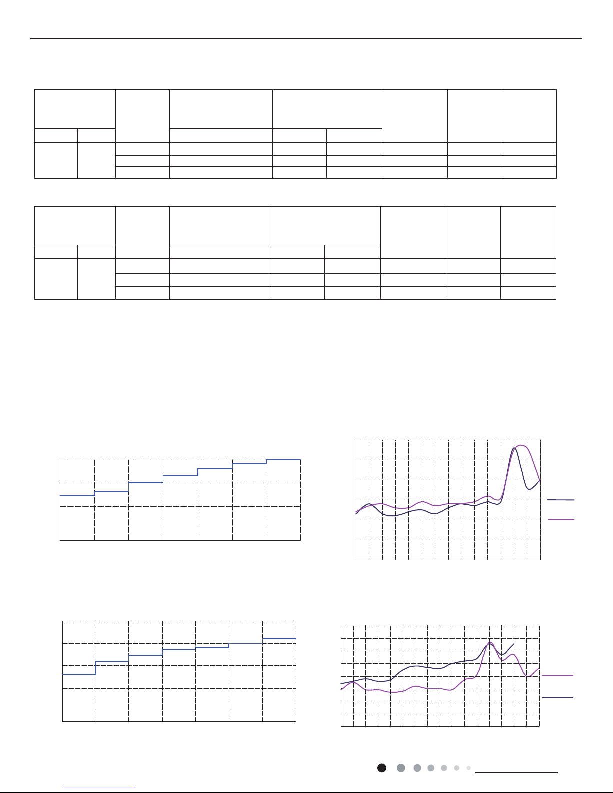
2.5 Noise Curve
20
30
40
Indoor side noise when blowing
Outdoor side noise when blowing
Indoor fan motor rotating speed
SH H HM M LM L SL
46
47
48
49
50
51
52
15 20 25 30 35 40 45 50 55 60 65 70 75 80 85
Noise dB(A)
Cooling
Heating
09K
12K
45
46
47
48
49
50
51
52
53
1 2 3 4 5 6 7 8 9 10 11 12 13 14 15 16 17
Compressor frequency(Hz)
Noise dB(A)
Cooling
Heating
Indoor side noise when blowing Outdoor side noise when blowing
Indoor fan motor rotating speed
SLLLMMHMHSH
20
30
40
50
11
Technical Information
Service Manual
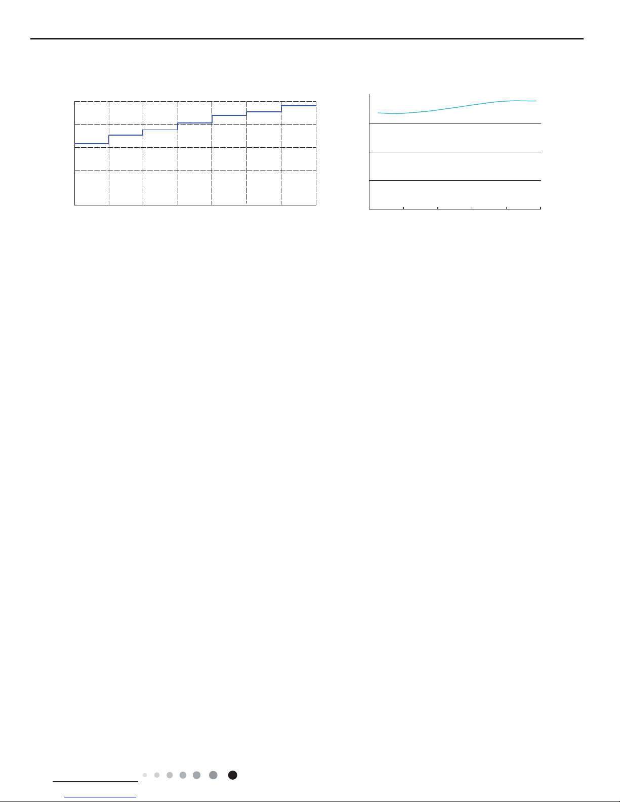
18K
Compressor frequency(Hz)
Indoor side noise when blowing Outdoor side noise when blowing
Indoor fan motor rotating speed
SLLLMMHMHSH
20
30
40
50
20
30
40
50
60
200 40 60 80 100
)A(Bd/esioN
12
Technical Information
Service Manual
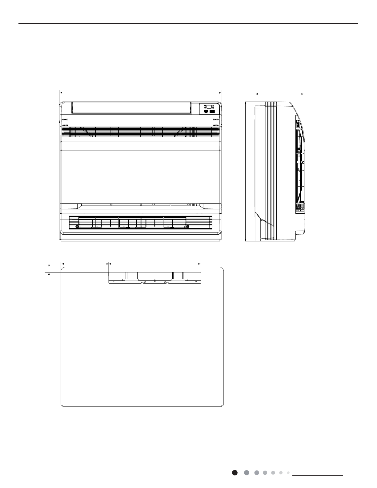
3. Outline Dimension Diagram
3.1 Indoor Unit
700
215
600
398
205
22
Unit:mm
13
Technical Information
Service Manual
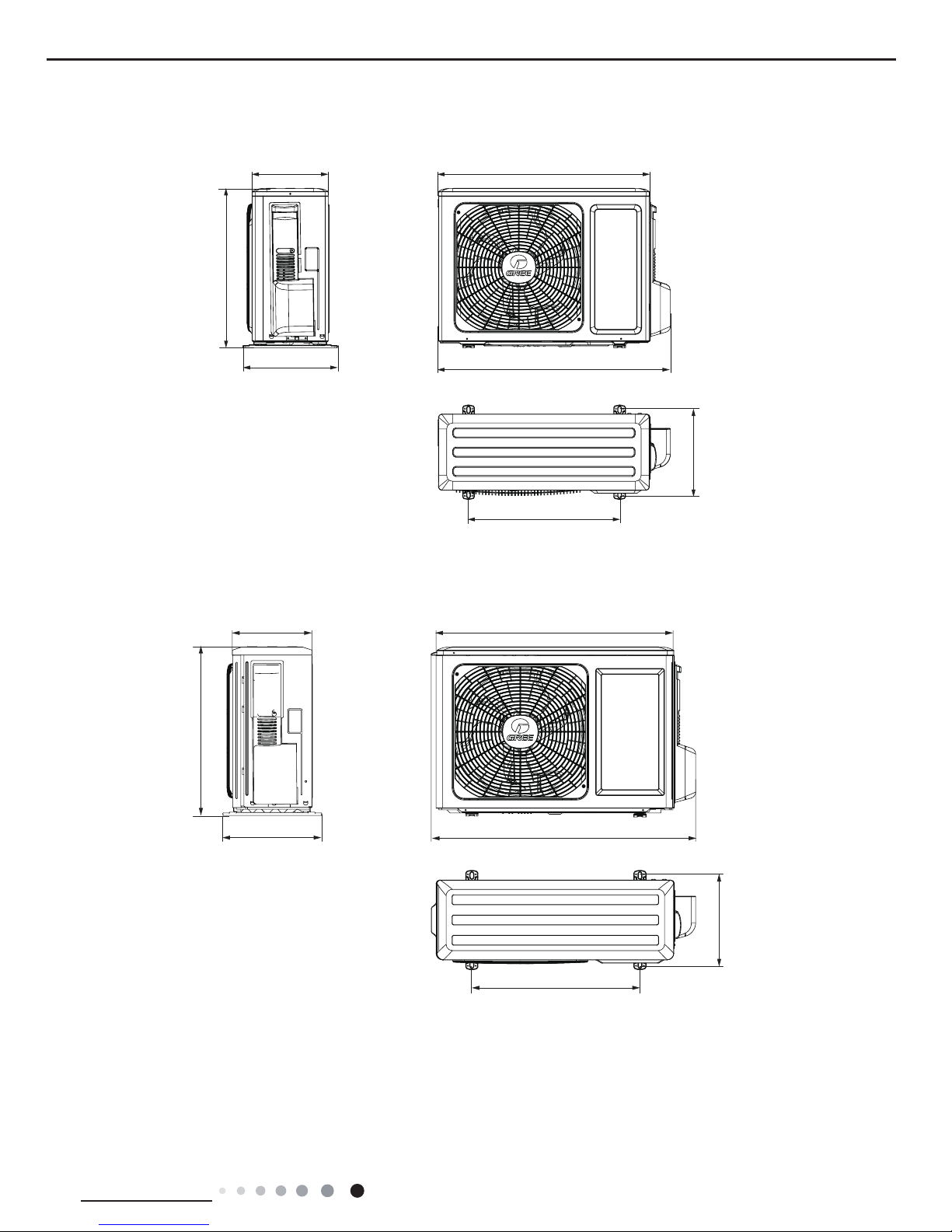
3.2 Outdoor Unit
762
848
257
320
540
286
540
712
766
257
320
540
286
510
09K
12K
Unit:mm
14
Technical Information
Service Manual
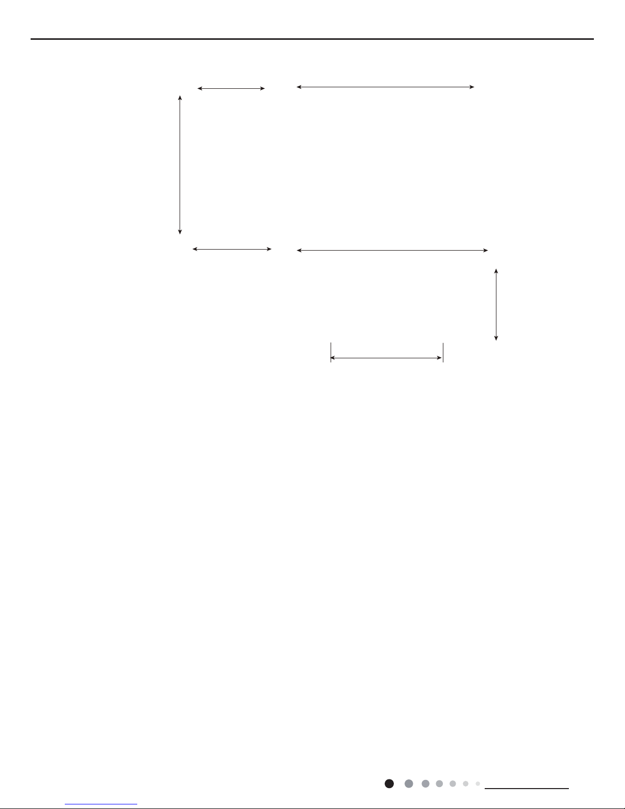
18K
963
892
700
396
341
368
560
15
Technical Information
Service Manual
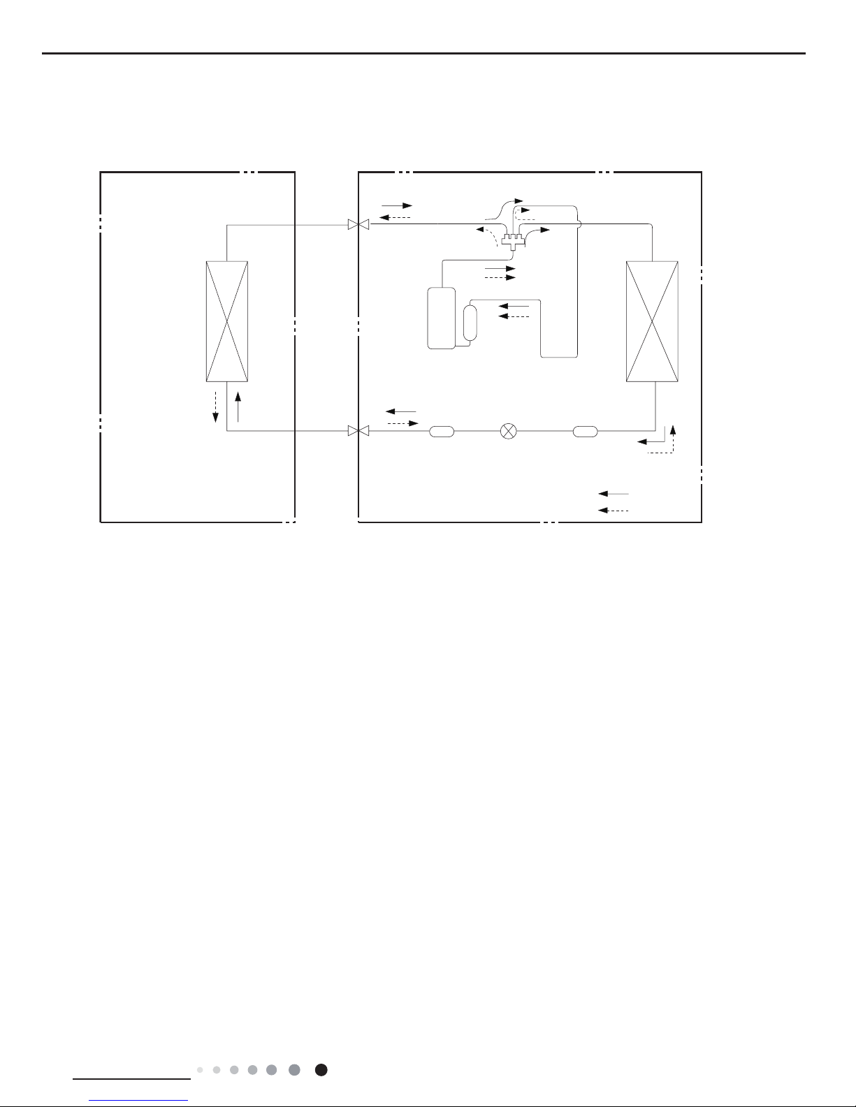
Indoor unit
Outdoor unit
COOLING
HEATING
4-Way valve
Discharge
Suction
Heat
exchanger
(evaporator)
Heat
exchanger
(condenser)
Valve
Valve
Liquid pipe
side
Gas pipe
side
Strainer
Electron
expansion
valve
Strainer
4. Refrigerant System Diagram
Connection pipe specication:
Liquid pipe:1/4" (6mm)
Gas pipe:3/8" (9.52mm)(09K/12K)
Gas pipe:1/2" (16mm)(18K)
16
Technical Information
Service Manual
5. Electrical Part
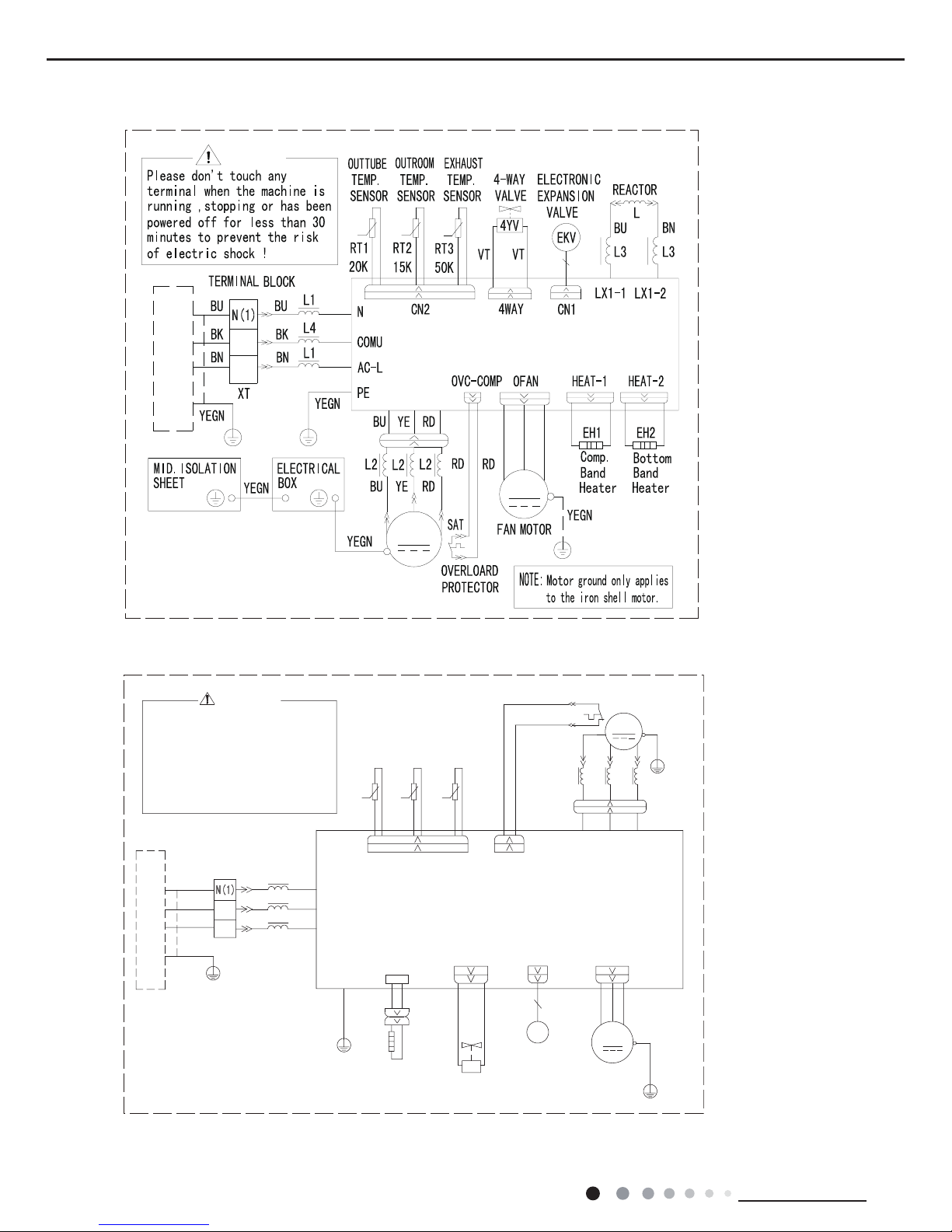
5.1 Wiring Diagram
● Indoor Unit
● Instruction
Symbol Symbol Color Symbol Symbol Color Symbol Name
WH White GN Green CAP Jumper cap
YE Yellow BN Brown COMP Compressor
RD Red BU Blue Grounding wire
YEGN Yellow/Green BK Black / /
VT Violet OG Orange / /
Note: Jumper cap is used to determine fan speed and the swing angle of horizontal lover for this model.
/
/
6:,7&+
<(*1
%.
%8
0
6:,1*'2:1
287'22581,7
&$3
-803
$335,17('&,5&8,7%2$5'
5220
57
57
78%(
6(1625 6(1625
52207(03
78%(7(03
32:(5
%8:+
/
1
1
',63/$<
5(&(,9(5$1'
',63/$<%2$5'
',63
$3
',63
0
)$1
'&02725
02725
67(33,1*
6:,1*83
0
$3
6
&1
6(/(&7
02725
67(33,1*
02725
%1%.
<(*1*1
1
;7
%1
&20287
$&/
%8
%.
%1
3(
(9$325$725
<(*1
7(50,1$/
%/2&.
/
(
(/(&75,&%2;
3(
<(*1
<(*1
/
0$*1(7,&
5,1*
&2/'3/$60$
*(1(5$725
+($/7+1
+($/7+/
; ;
5' %8
5' %8
17
Technical Information
Service Manual
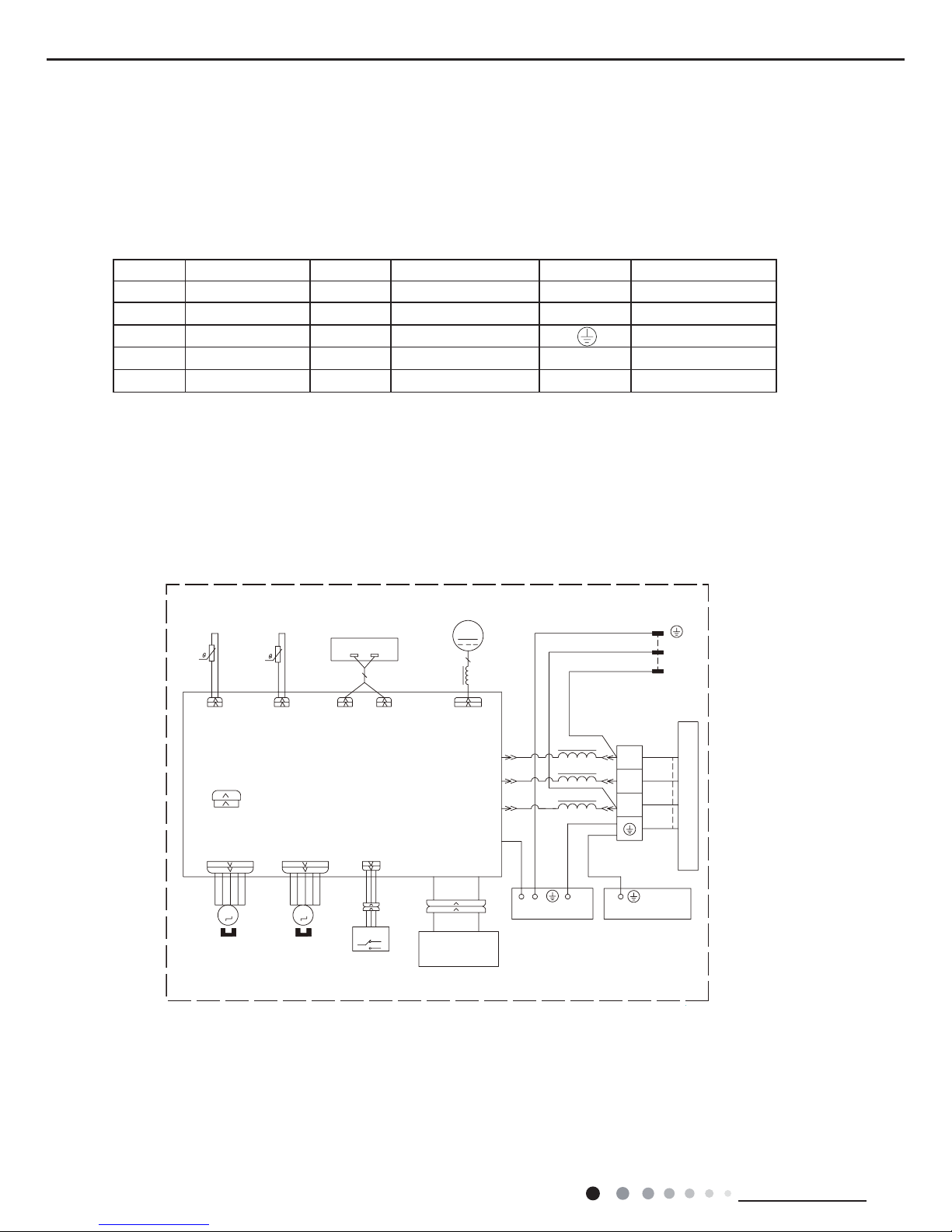
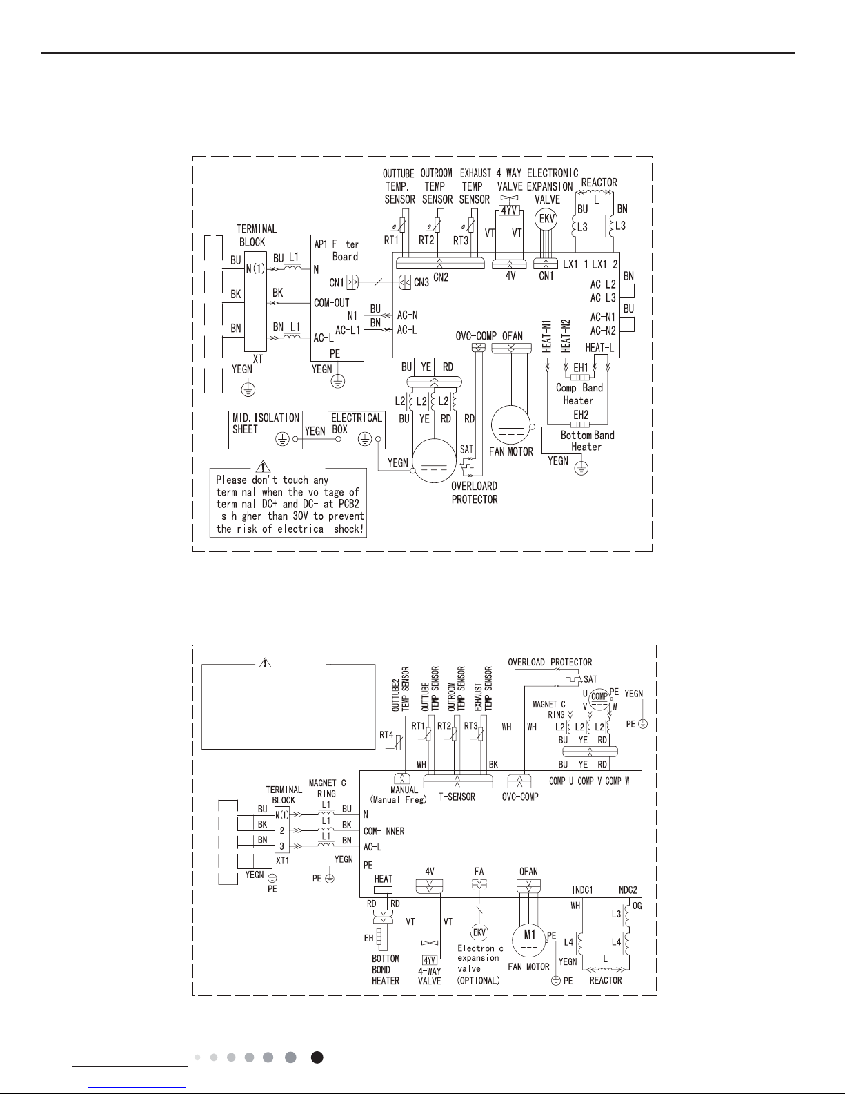
● Outdoor Unit
3(
,1'22581,7
:$51,1*
8
9
:
&203
&203
8
9
:
3(
3(
3(
3(
$30DLQ%RDUG
3(
3(
0
GEH18AA-K3DNA1B/O
$3
&203
;
,1'22581,7
3OHDVHGRQWWRXFKDQ\
HOHFWURQLFFRPSRQHQWRU
WHUPLQDOZKHQWKHPDFKLQHLV
UXQQLQJVWRSSLQJRUKDV
EHHQSRZHUHGRIIIRUOHVV
WKDQPLQXWHVWRSUHYHQW
WKHULVNRIHOHFWULFVKRFN
:$51,1*
©
©
©
©
GEH09AA-K3DNA1B/O GEH12AA-K3DNA1B/O
18
Technical Information
Service Manual
These circuit diagrams are subject to change without notice, please refer to the one supplied with the unit.
%1
%.
%8
YDOYH
H[SDQVLRQ
<(*1
(OHFWURQLF
)$
(.9
<(*1
$3
%/2&.
7(50,1$/
)$1027253(<(*1
7(036(1625
(;+$867
7(036(1625
2875220
28778%(
7(036(1625
%.:+
%8 <(
&203
;
&203
6$7
:+ :+
29&B&203
2)$1
3(
5'
0
575757
&20B,11(5
3(
3(
:98
5'%8 <(
1
$&B/
<(*1
7B6(1625
%8
%1
%.
;7
3(
,1'22581,7
29(5/2$' 3527(&725
/
/
0$*1(7,&
5,1*
0$*1(7,&
5,1*
/
/
//
:$<
<9
:$<
9$/9(
97 97
3(
3(
+($7B%
5'5'
%$1'
+($7(5
%27720
(+
3OHDVHGRQWWRXFKDQ\
WHUPLQDOZKHQWKHYROWDJH
RIWHUPLQDO3'&DQG
1'&DW$3LVKLJKHU
WKDQ9WRSUHYHQWWKH
ULVNRIHOHFWULFVKRFN
:$51,1*
0$,1%2$5'
. . .
:5'9<(8%8
GEH18AA-K3DNA1C/O
GEH09AA-K3DNA1C/O GEH12AA-K3DNA1C/O
,1'22581,7
8
9
:
&203
&203
8
9
:
3(
3(
3(
3(
$30DLQ%RDUG
3(
3(
0
3(
:$51,1*
19
Technical Information
Service Manual
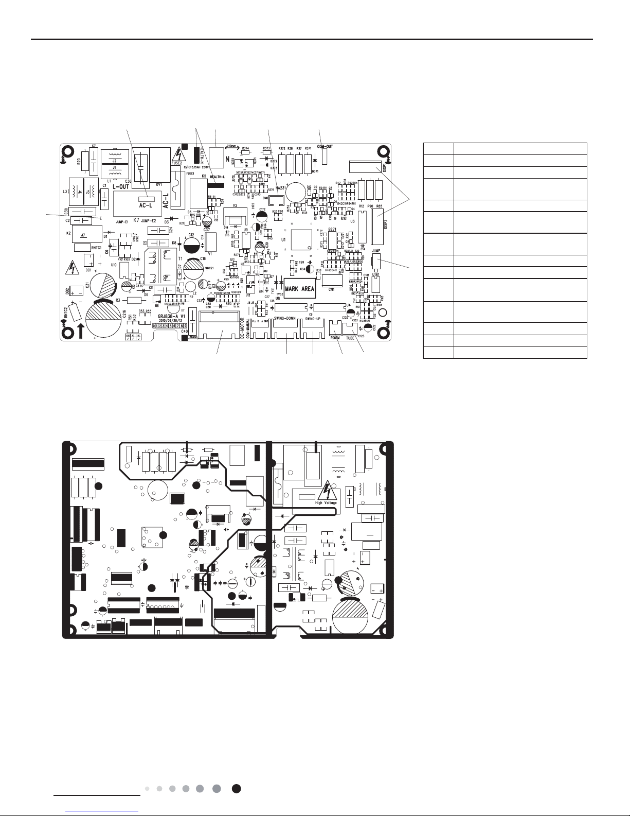
5.2 PCB Printed Diagram
Indoor Unit
● Top view
● Bottom view
No. Name
1 Connect earthing wire
2 Input of live wire
3
Wiring terminal for health
function (optional)
4 Input of neutral wire
5
Control the wiring terminal of
down swing
6
Communication interface for
indoor unit and outdoor unit
7 Terminal of display interface
8 Needle stand of jumper cap
9
Wiring terminal of indoor tube
temperature sensor
10
Wiring terminal of indoor
ambient temperature sensor
11
Wiring terminal of up swing
12 Wiring terminal of down swing
13 Wiring terminal of DC motor
1
2
3
4
5
6
7
8
9
10
1112
13
20
Technical Information
Service Manual
1
2 3 4
5
6
7
8
9
10
● Top view
Outdoor Unit
● Bottom view
GEH09AA-K3DNA1B/O GEH12AA-K3DNA1B/O
No.
Name
1 Leading foot 1 of induction
2 4-way valve
3 Electric heating of compressor
4 Electric heating of chassis
5 Fan
6 10-core communication wire
7 Electronic expansion valve
8 Overload protection
9 Temperature sensor
10 Leading foot 2 of induction

21
Technical Information
Service Manual
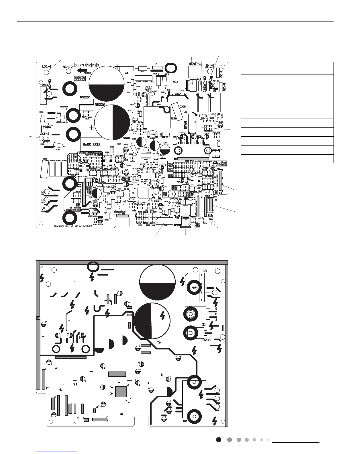
1 2 3 4 5
6
78910
● Top view
● Bottom view
GEH09AA-K3DNA1C/O GEH12AA-K3DNA1C/O
1
Live wire input of Dred
communication plate
2 Heating belt 1
3 Heating belt 2
4 4-way valve
5
Neutral wire input of Dred
communication plate
6 Dred function terminal
7
Electronic expansion valve
terminal
8
Overload terminal of
compressor
9
Overload terminal of
compressor
10 Temperature sensor terminal

22
Technical Information
Service Manual
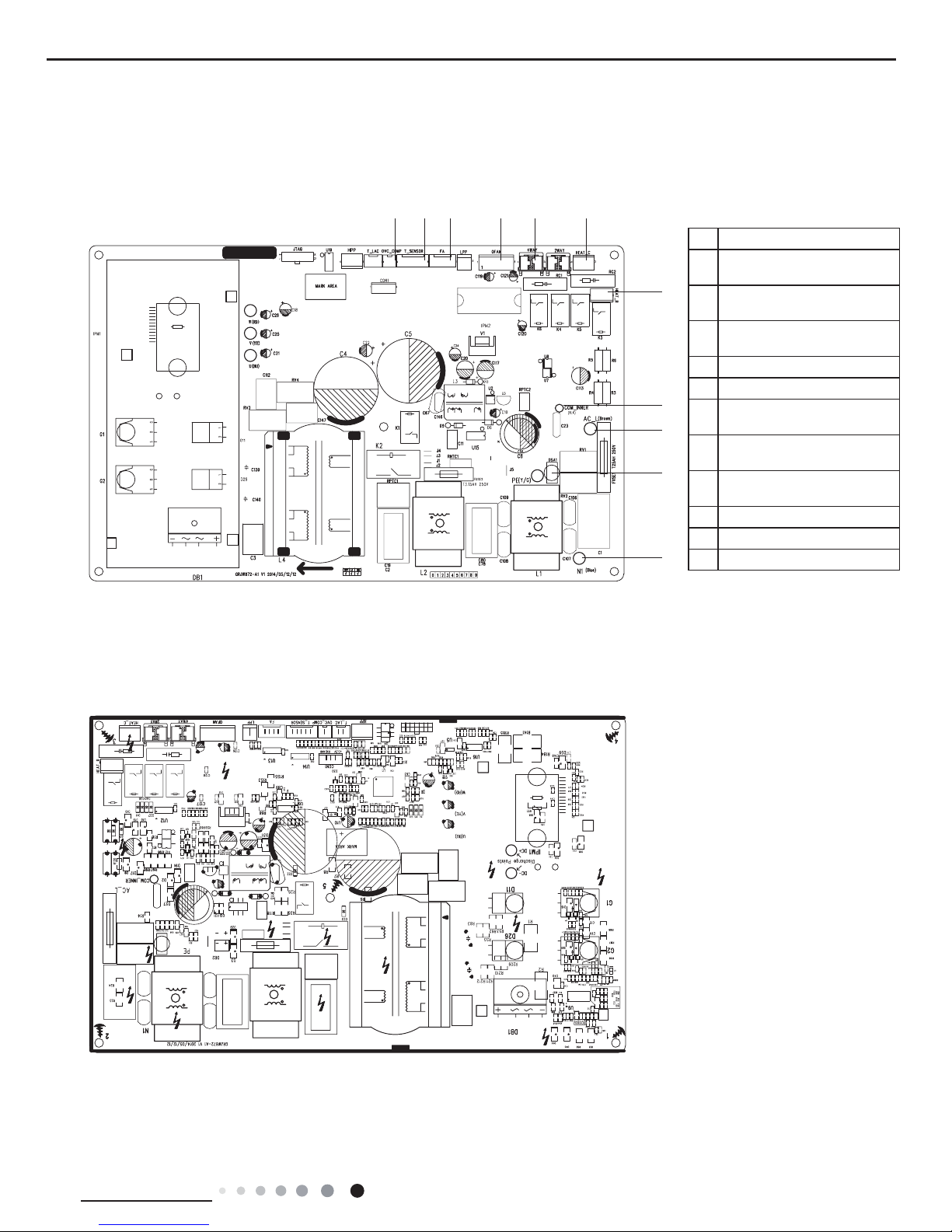
1
12
2 3
4 5
6
7
8
9
10
11
● Bottom view
No. Name
1
Wiring terminal of
compressor
2
Overload protection
terminal of compressor
3
Terminal of outdoor
temperature sensor
4
Terminal of electronic
expansion valve
5 Terminal of outdoor fan
6 Terminal of 4-way valve
7
Wiring terminal of
chassis electric heater
8
Communication wire
with IDU
5 Terminal of outdoor fan
6 Terminal of 4-way valve
7
Wiring terminal of
chassis electric heater
8
Communication wire
with IDU
9
Live wire of power
supply
10 Grounding wire
11
Neutral wire of power
supply
12 PFC induction wire
● Top view
GEH18AA-K3DNA1B/O
23
Technical Information
Service Manual
No. Name
1
Terminal of compressor
overload protection
2
Terminal of temperature
sensor
3
Terminal of electronic
expansion valve
4
Terminal of outdoor fan
5
Terminal of 4-way valve
6
Terminal of
compressorelectric heating
7
Terminal of chassis electric
heating
8
Terminal of indoor unit and
outdoor unit communication
9
Power supply live wire
10
Earthing wire
11
Power supply neutral wire
1 2 3 4 5 6
7
8
9
10
11
● Bottom view
● Top view
GEH18AA-K3DNA1C/O
 Loading...