

Gree GEH12AA-K6DNA1A/O, GEH12AA-K6DNA1A, GEH18AA-K6DNA1F/O, GEH18AA-K6DNA1F, GEH09AA-K6DNA1F/I Service Manual
...
Change for life
Service Manual
GREE ELECTRIC APPLIANCES, INC. OF ZHUHAI

Table of Contents
Service Manual
Part
1. Summary
2. Specications
2.1 Specication Sheet ...........................................................................................................3
2.2 Operation Characteristic Curve ........................................................................................7
2.3 Capacity Variation Ratio According to Temperature .........................................................7
2.4 Noise Curve ......................................................................................................................8
3. Outline Dimension Diagram
3.1 Indoor Unit ........................................................................................................................9
3.2 Outdoor Unit ...................................................................................................................10
: Technical Information
Ⅰ
......................................................................................................................1
..........................................................................................................3
.........................................................................................9
4. Refrigerant System Diagram
5. Electrical Part
5.1 Wiring Diagram ...............................................................................................................13
5.2 PCB Printed Diagram .....................................................................................................17
6. Function and Control
.........................................................................................................13
......................................................................................20
.......................................................................1
....................................................................12
6.1 Remote Controller Introduction .....................................................................................20
6.2 GREE+ App Operation Manual ......................................................................................24
6.3 Ewpe Smart App Operation Manual ...............................................................................25
6.4 Brief Description of Modes and Functions ......................................................................26
Part
: Installation and Maintenance
Ⅱ
7. Notes for Installation and Maintenance
8. Installation
8.1 Requirements for Electric Connection ............................................................................32
8.2 Installation of indoor unit ................................................................................................32
8.3 Outdoor Unit Installation .................................................................................................38
8.4 Vacuum Pumping and Leak Detection ...........................................................................39
8.5 Check after Installation and Test Operation ...................................................................39
9. Maintenance
9.1 Error Code List ...............................................................................................................40
................................................................................................................32
............................................................................................................40
.................................................28
..........................................28
9.2 Procedure of Troubleshooting ........................................................................................47
9.3 Maintenance Method for Normal Malfunction .................................................................60
Table of Contents

Service Manual
10. Exploded View and Parts List
10.1 Indoor Unit ....................................................................................................................62
10.2 Outdoor Unit .................................................................................................................65
11. Removal Procedure
11.1 Removal Procedure of Indoor Unit ...............................................................................71
11.2 Removal Procedure of Outdoor Unit ............................................................................75
Appendix:
Appendix 1: Reference Sheet of Celsius and Fahrenheit ....................................................90
Appendix 2: Conguration of Connection Pipe .....................................................................90
Appendix 3: Pipe Expanding Method ...................................................................................91
Appendix 4: List of Resistance for Temperature Sensor ......................................................92
........................................................................................................................90
.......................................................................................71
..............................................................62
Service Manual
Part
Ⅰ
: Technical Information
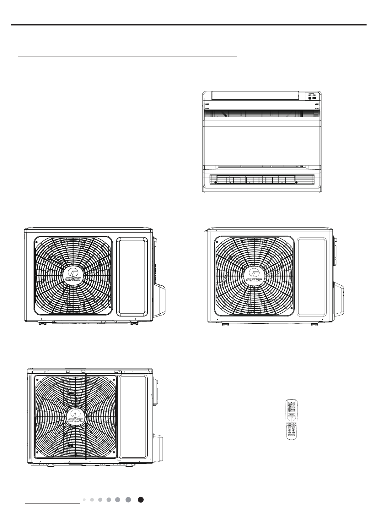
1. Summary
Indoor Unit
GEH12AA-K6DNA1A/I
GEH09AA-K6DNA1F/I
GEH18AA-K6DNA1F/I
Outdoor Unit
GEH09AA-K6DNA1F/O
GEH12AA-K6DNA1A/O
GEH18AA-K6DNA1F/O
Technical Information
Remote Controller
YAA1FB8(WiFi)
1

Model List:
Service Manual
No Model Product code Indoor model
1
GEH09AA-K6DNA1F
2 CV010002701 CV010N02701
3
GEH12AA-K6DNA1A
4 CV010002901 CV010N02901
5
GEH18AA-K6DNA1F
6 CV010002801 CV010N02801
CV010002700
CV010002900
CV010002800
GEH09AA-K6DNA1F/I
GEH12AA-K6DNA1A/I
GEH18AA-K6DNA1F/I
Indoor product
code
CV010N02700
CV010N02900
CV010N02800
Outdoor model
GEH09AA-K6DNA1F/O CV010W02700
GEH12AA-K6DNA1A/O CV010W02900
GEH18AA-K6DNA1F/O CV010W02800
Outdoor product
code
Remote
Controller
YAA1FB8(WiFi)
2
Technical Information
Service Manual
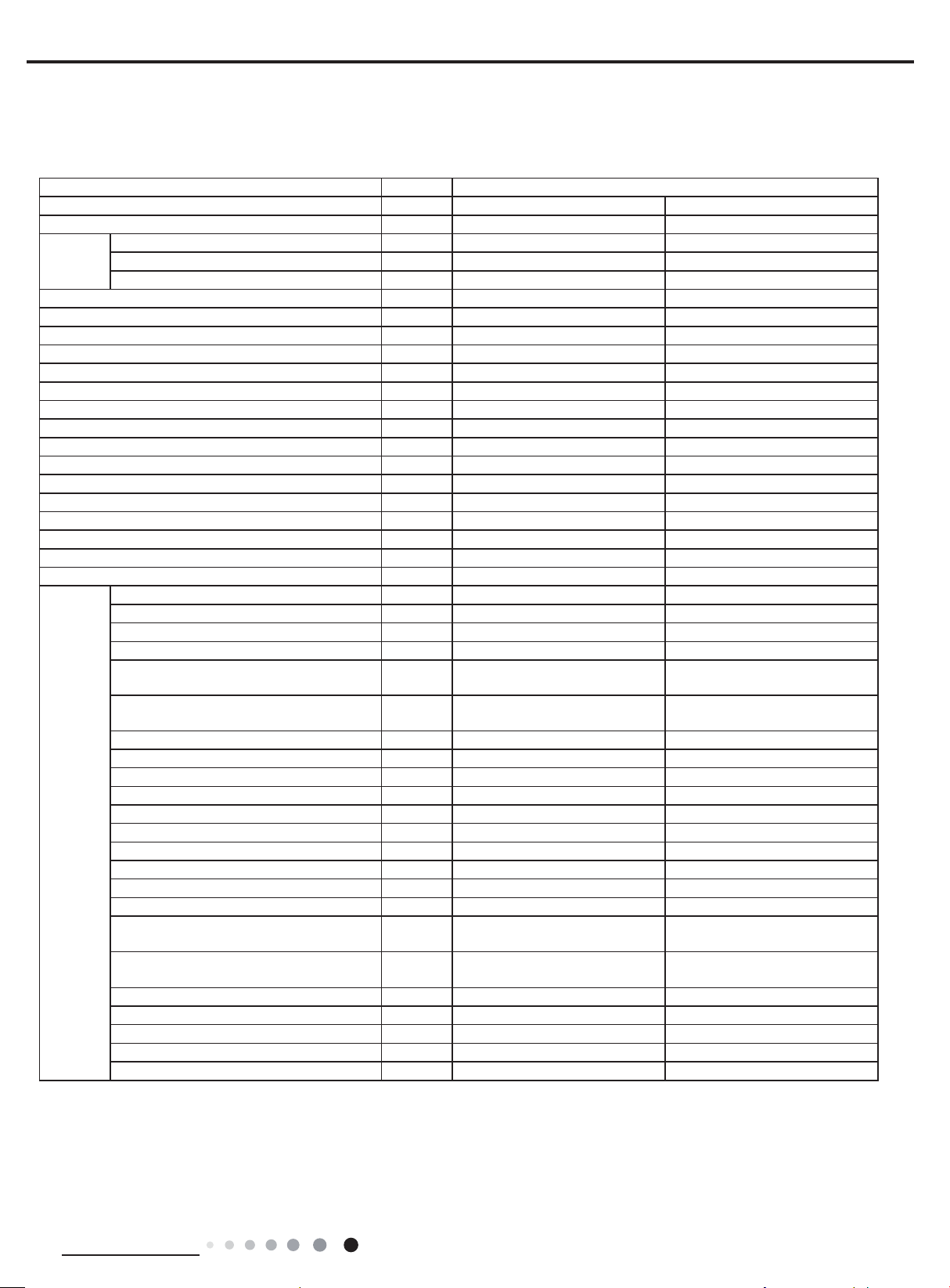
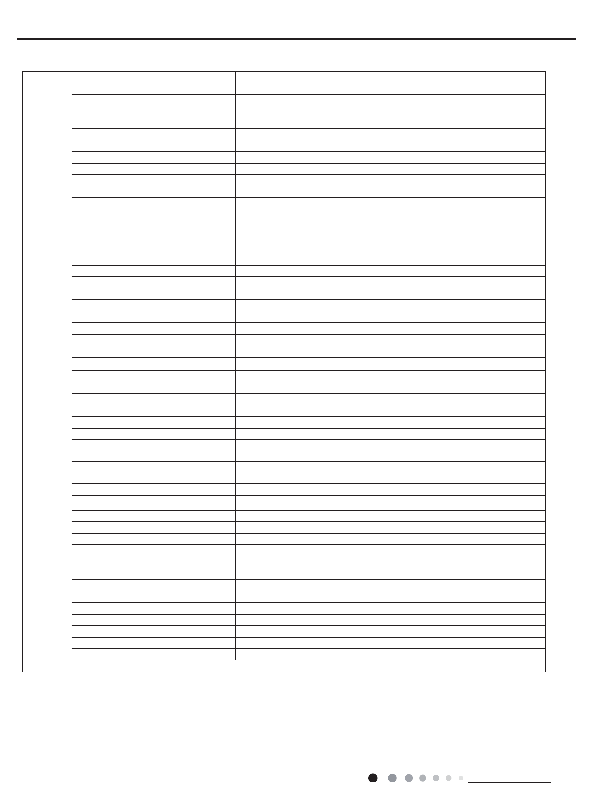
2. Specications
2.1 Specication Sheet
Parameter Unit Value
Model GEH12AA-K6DNA1A GEH09AA-K6DNA1F
Product Code CV010002900/CV010002901 CV010002700/CV010002701
Power
Supply
Power Supply Mode Outdoor Outdoor
Cooling Capacity(Min~Max) W 3520(800~4400) 2700(700~3400)
Heating Capacity(Min~Max) W 3800(1100~4400) 2900(600~3500)
Cooling Power Input(Min~Max) W 1000(160~1500) 720(170~1300)
Heating Power Input(Min~Max) W 960(165~1500) 730(130~1350)
Cooling Current Input A 4.48 3.5
Heating Current Input A 4.30 3.6
Rated Input W 1500 1350
Rated Current A 6.72 6.0
Air Flow Volume(SH/H/HM/M/LM/L/SL) m3/h 600/520/480/440/400/360/280 500/430/410/370/330/280/250
Dehumidifying Volume L/h 1.2 0.8
EER W/W 3.52 3.75
COP W/W 3.96 3.97
SEER W/W 7.0 7.2
SCOP(Average/Warmer/Colder) W/W 4.1/5.3/- 4.0/5.3/Application Area m
Indoor
Unit
Rated Voltage V
Rated Frequency Hz 50 50
Phases 1 1
Indoor Unit Model GEH12AA-K6DNA1A/I GEH09AA-K6DNA1F/I
Indoor Unit Product Code CV010N02900/CV010N02901 CV010N02700/CV010N02701
Fan Type Centrifugal Centrifugal
Fan Diameter Length(DXL) mm Φ370X80 Φ370X80
Cooling Speed
(SH/H/HM/M/LM/L/SL)
Heating Speed
(SH/H/HM/M/LM/L/SL)
Fan Motor Power Output W 30 30
Fan Motor RLA A 0.15 0.15
Fan Motor Capacitor μF / /
Evaporator Form Aluminum Fin-copper Tube Aluminum Fin-copper Tube
Evaporator Pipe Diameter mm Φ7 Φ7
Evaporator Row-n Gap mm 2-1.3 2-1.3
Evaporator Coil Length (LXDXW) mm 511X400X25.4 511X400X25.4
Swing Motor Model MP24EB/MP24AE MP24EB/MP24AE
Swing Motor Power Output W 1.5/1.5 1.5/1.5
Fuse Current A 3.15 3.15
Sound Pressure Level
(SS/H/MH/M/ML/L/SL)
Sound Power Level
(SS/H/MH/M/ML/L/SL)
Dimension (WXHXD) mm 700X215X600 700X215X600
Dimension of Carton Box (LXWXH) mm 785X280X682 785X280X682
Dimension of Package(LXWXH) mm 788X295X685 788X295X685
Net Weight kg 15.5 15.5
Gross Weight kg 18.5 18.5
~
2
r/min 750/650/600/550/500/450/350 650/560/530/480/430 /370/320
r/min 750/650/600/550/500/450/350 650/560/530/480/430/370/320
dB (A)
dB (A)
Cooling:44/40/38/36/33/29/25
Heating:44/40/38/36/33/29/25
Cooling:54/50/48/46/43/39/35
Heating:54/50/48/46/43/39/35
220-240 220-240
16-24 12-18
Cooling:39/36/33/31/29/26/23
Heating:38/36/32/30/28/25/22
Cooling:50/48/45/44/42/38/34
Heating:50/48/45/44/42/38/34
Technical Information
3
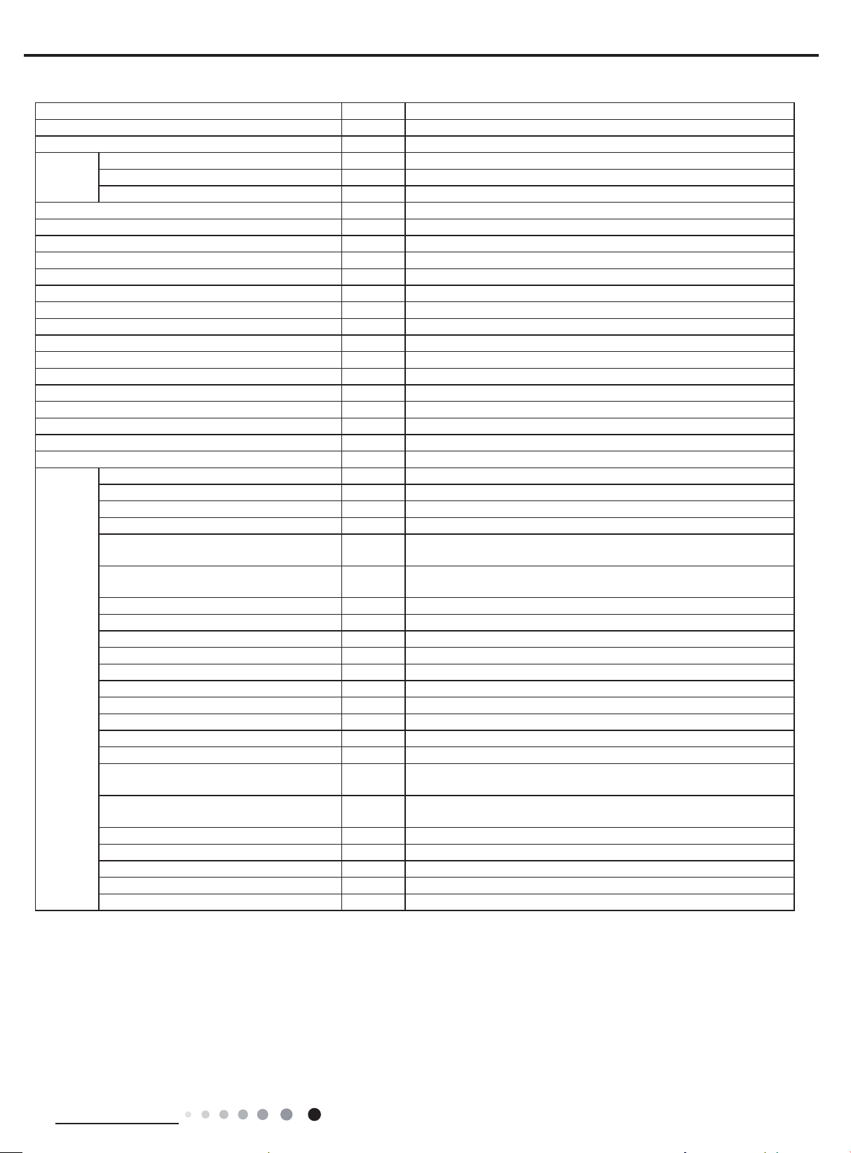
Outdoor
Unit
Connection
Pipe
Service Manual
Outdoor Unit Model GEH12AA-K6DNA1A/O GEH09AA-K6DNA1F/O
Outdoor Unit Product Code CV010W02900 CV010W02700
Compressor Manufacturer
Compressor Model QXF-A102zE190B QXF-A079zE190A
Compressor Oil FW68DA FW68DA
Compressor Type Rotary Rotary
Compressor LRA. A / /
Compressor RLA A 4.60 4.6
Compressor Power Input W 1023 790
Compressor Overload Protector HPC115/95U1/KSD115ºC HPC115/95U1/KSD115ºC
Throttling Method Electron expansion valve Electron expansion valve
Set Temperature Range ºC 16~30 16~30
Cooling Operation Ambient Temperature
Range
Heating Operation Ambient Temperature
Range
Condenser Form Aluminum Fin-copper Tube Aluminum Fin-copper Tube
Condenser Pipe Diameter mm Φ7.94 Φ7
Condenser Rows-n Gap mm 1-1.4 1-1.4
Condenser Coil Length (LXDXW) mm 731X19.05X550 710X19.05X508
Fan Motor Speed rpm 900 900
Fan Motor Power Output W 30 30
Fan Motor RLA A 0.36 0.36
Fan Motor Capacitor μF / /
Outdoor Unit Air Flow Volume m3/h 2200 1600
Fan Type Axial-ow Axial-ow
Fan Diameter mm Φ438 Φ400
Defrosting Method Automatic Defrosting Automatic Defrosting
Climate Type T1 T1
Isolation I I
Moisture Protection IPX4 IPX4
Permissible Excessive Operating
Pressure for the Discharge Side
Permissible Excessive Operating
Pressure for the Suction Side
Sound Pressure Level (H/M/L) dB (A) 52/-/- 49/-/-
Sound Power Level (H/M/L) dB (A) 62/-/- 60/-/-
Dimension(WXHXD) mm 848X596X320 782X540X320
Dimension of Carton Box (LXWXH) mm 878X360X630 820X355X580
Dimension of Package(LXWXH) mm 881X363X645 823X358X595
Net Weight kg 30.5 27.5
Gross Weight kg 33.5 30
Refrigerant R32 R32
Refrigerant Charge kg 0.75 0.55
Connection Pipe Length m 5 5
Connection Pipe Gas Additional Charge g/m 16 16
Outer Diameter Liquid Pipe mm Φ6 Φ6
Outer Diameter Gas Pipe mm Φ9.52 Φ9.52
Max Distance Height m 10 10
Max Distance Length m 20 20
Note: The connection pipe applies metric diameter.
MPa 4.3 4.3
MPa 2.5 2.5
ZHUHAI LANDA COMPRESSOR
CO.,LTD
ºC -15~43 -15~43
ºC -22~24 -22~24
ZHUHAI LANDA COMPRESSOR
CO., LTD
The above data is subject to change without notice. Please refer to the nameplate of the unit.
4
Technical Information
Service Manual
Parameter Unit Value
Model GEH18AA-K6DNA1F
Product Code CV010002800/CV010002801
Power
Supply
Rated Voltage V
~
Rated Frequency Hz 50
Phases 1
220-240
Power Supply Mode Outdoor
Cooling Capacity(Min~Max) W 5200(1260~6600)
Heating Capacity(Min~Max) W 5330(1120~6800)
Cooling Power Input(Min~Max) W 1550(380~2450)
Heating Power Input(Min~Max) W 1500(350~2500)
Cooling Current Input A 7.1
Heating Current Input A 6.7
Rated Input W 2500
Rated Current A 11.1
Air Flow Volume(SH/H/HM/M/LM/L/SL) m3/h 700/650/580/520/460/410/320
Dehumidifying Volume L/h 1.8
EER W/W 3.4
COP W/W 3.55
SEER W/W 6.6
SCOP(Average/Warmer/Colder) W/W /
Application Area m
2
23-34
Indoor Unit Model GEH18AA-K6DNA1F/I
Indoor Unit Product Code CV010N02800/CV010N02801
Fan Type Centrifugal
Fan Diameter Length(DXL) mm Φ370X80
Cooling Speed
(SH/H/HM/M/LM/L/SL)
Heating Speed
(SH/H/HM/M/LM/L/SL)
r/min
r/min
840/800/720/650/580/530/410
810/770/690/620/550/500/380
930/840/760/690/620/570/480
850/800/720/650/580/530/470
Fan Motor Power Output W 30
Fan Motor RLA A 0.15
Fan Motor Capacitor μF /
Evaporator Form Aluminum Fin-copper Tube
Indoor
Unit
Evaporator Pipe Diameter mm Φ7
Evaporator Row-n Gap mm 2-1.3
Evaporator Coil Length (LXDXW) mm 511X400X25.4
Swing Motor Model MP24EB/MP24AE
Swing Motor Power Output W 1.5/1.5
Fuse Current A 3.15
Sound Pressure Level
(SS/H/MH/M/ML/L/SL)
Sound Power Level
(SS/H/MH/M/ML/L/SL)
dB (A) 47/45/42/40/37/35/31
dB (A) 57/55/52/50/47/45/41
Dimension (WXHXD) mm 700X215X600
Dimension of Carton Box (LXWXH) mm 785X280X682
Dimension of Package(LXWXH) mm 788X283X697
Net Weight kg 15.5
Gross Weight kg 18.5
Technical Information
5
Outdoor
Unit
Connection
Pipe
Outdoor Unit Model GEH18AA-K6DNA1F/O
Outdoor Unit Product Code CV010W02800
Compressor Manufacturer ZHUHAI LANDA COMPRESSOR CO.,LTD
Compressor Model QXF-B141zF030A
Compressor Oil 68DA
Compressor Type Rotary
Compressor LRA. A 25
Compressor RLA A 6.5
Compressor Power Input W 1410
Compressor Overload Protector 1NT11L-6233 or KSD115ºC or HPC115/95U1
Throttling Method Electron expansion valve
Set Temperature Range ºC 16~30
Cooling Operation Ambient Temperature
Range
Heating Operation Ambient Temperature
Range
Condenser Form Aluminum Fin-copper Tube
Condenser Pipe Diameter mm Φ7
Condenser Rows-n Gap mm 2-1.4
Condenser Coil Length (LXDXW) mm 851X38.1X660
Fan Motor Speed rpm 800
Fan Motor Power Output W 60
Fan Motor RLA A 0.4
Fan Motor Capacitor μF /
Outdoor Unit Air Flow Volume m3/h 3200
Fan Type Axial-ow
Fan Diameter mm Φ520
Defrosting Method Automatic Defrosting
Climate Type T1
Isolation I
Moisture Protection IPX4
Permissible Excessive Operating
Pressure for the Discharge Side
Permissible Excessive Operating
Pressure for the Suction Side
Sound Pressure Level (H/M/L) dB (A) 57/-/-
Sound Power Level (H/M/L) dB (A) 65/-/-
Dimension(WXHXD) mm 965X700X396
Dimension of Carton Box (LXWXH) mm 1026X455X735
Dimension of Package(LXWXH) mm 1029X458X750
Net Weight kg 46
Gross Weight kg 50.5
Refrigerant R410A
Refrigerant Charge kg 0.95
Connection Pipe Length m 5
Connection Pipe Gas Additional Charge g/m 20
Outer Diameter Liquid Pipe mm Φ6
Outer Diameter Gas Pipe mm Φ12
Max Distance Height m 10
Max Distance Length m 25
Note: The connection pipe applies metric diameter.
ºC -15~43
ºC -22~24
MPa 4.3
MPa 2.5
Service Manual
The above data is subject to change without notice. Please refer to the nameplate of the unit.
6
Technical Information
Service Manual
10
gnilooC
Capacity ratio(%)
gnitaeH
Outdoor temp.(°C)
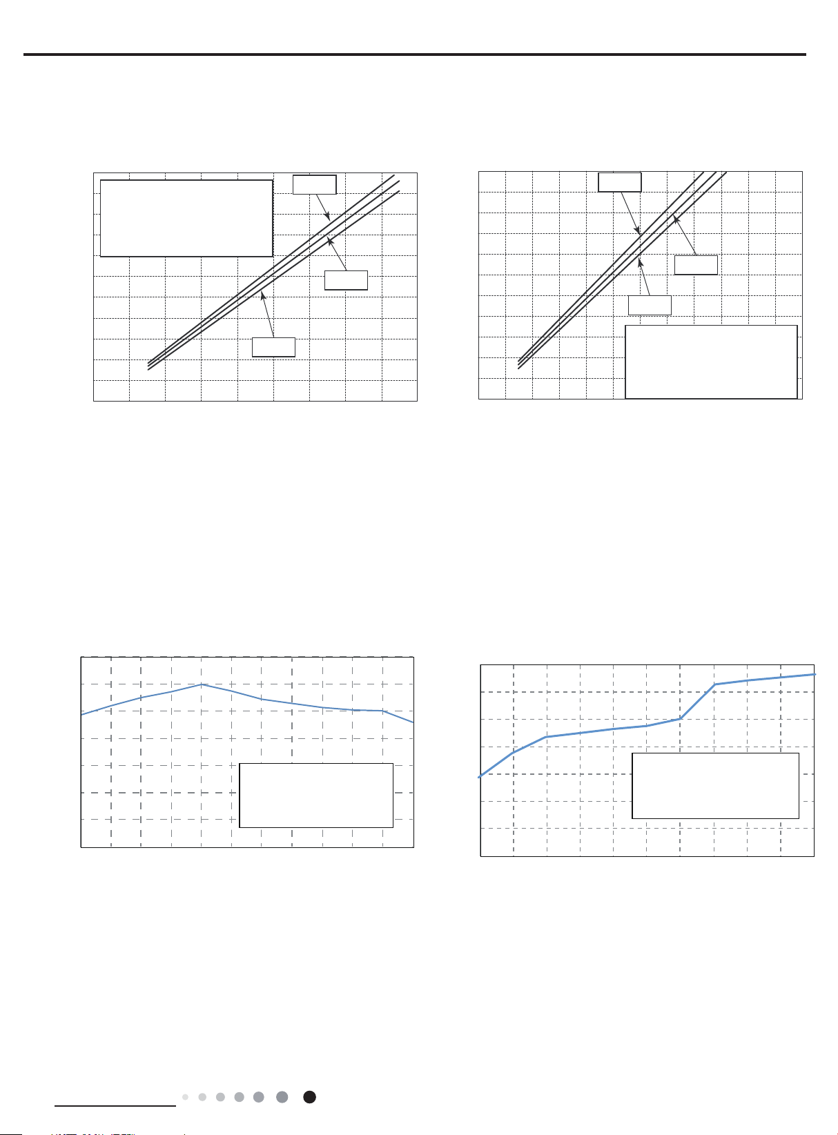
2.2 Operation Characteristic Curve
Cooling
11
10
9
8
7
6
5
Current (A)
4
3
2
1
0
• Conditions
Indoor : DB27˚C/WB19˚C
Outdoor : DB35˚C/WB24˚C
Indoor air flow : High
Pipe length : 5m
Compressor frequency(Hz)
240V
220V
230V
80
09070605040302010
Heating
11
10
9
8
7
6
5
Current (A)
4
3
2
1
0
220V
230V
240V
• Conditions
Indoor : DB20˚C/WB15˚C
Outdoor: DB7˚C/WB6˚C
Indoor air flow : High
Pipe length : 5m
Compressor frequency(Hz)
0
1
210010908070605040302010
2.3 Capacity Variation Ratio According to Temperature
140
120
100
80
60
Condition
40
20
0
-15-10 -5 0510 15 20 25 30 35 43
Indoor:DB27°C WB19°C
Indoor air flow:
High
Pipe length:5m
Outdoor temp.(°C)
140
120
%)
100
80
60
40
Capacity ratio(
20
0
-22 -15 -10 -7 0 2 7 15 18 21 24
Conditions
Indoor:DB20°C
Indoor air flow:Super High
Pipe length:5m
Technical Information
7
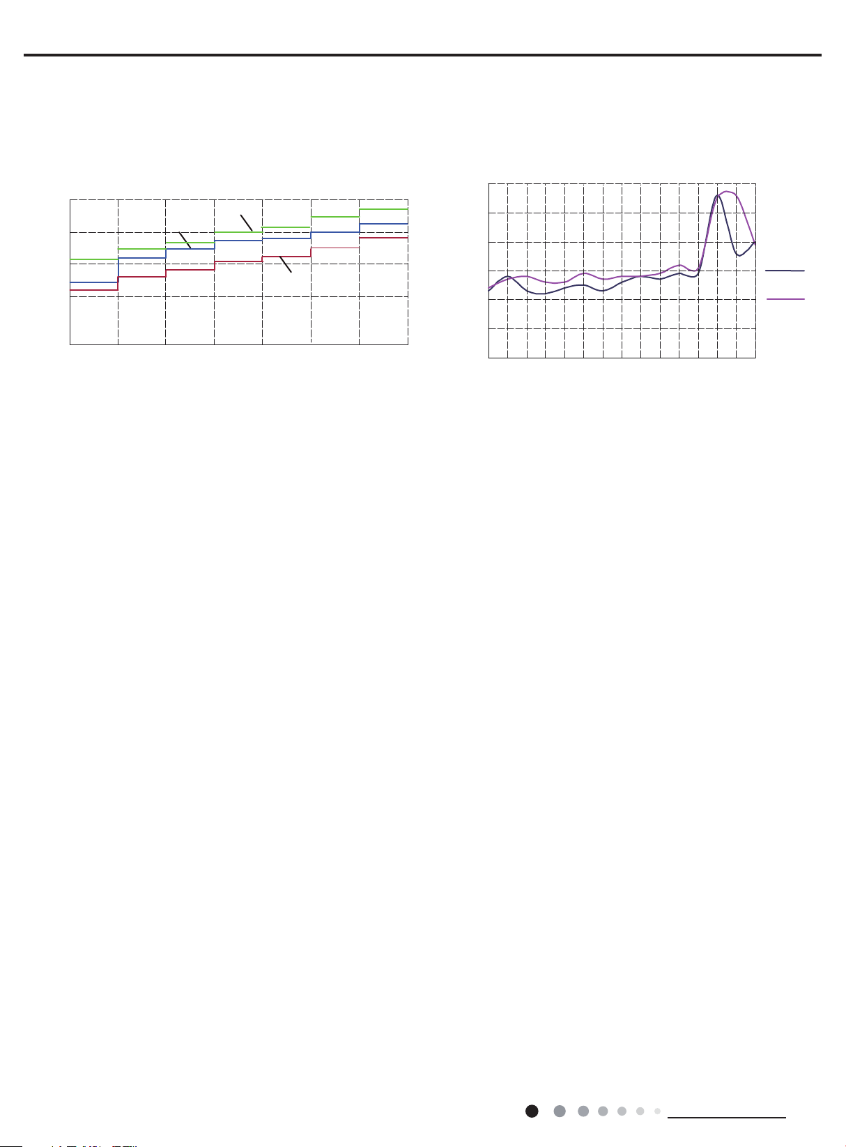
2.4 Noise Curve
45
46
47
48
49
50
51
52
53
12345678910 11 12 13 14 15 16 17
Compressor frequency(Hz)
Noise dB(A)
Cooling
Heating
Indoor side noise when blowing Outdoor side noise when blowing
20
30
40
50
Outdoor side noise when blowing
Heating
Compressor frequency(Hz)
Service Manual
52
12K
SL LLM
Indoor fan motor rotating speed
18K
09K
MHMHSH
51
50
49
48
Noise dB(A)
47
46
15 20 25 30 35 40 45 50 55 60 65 70 75 80 85
Cooling
8
Technical Information

Service Manual
3. Outline Dimension Diagram
3.1 Indoor Unit
22
205
700
215
600
398
Technical Information
Unit:mm
9
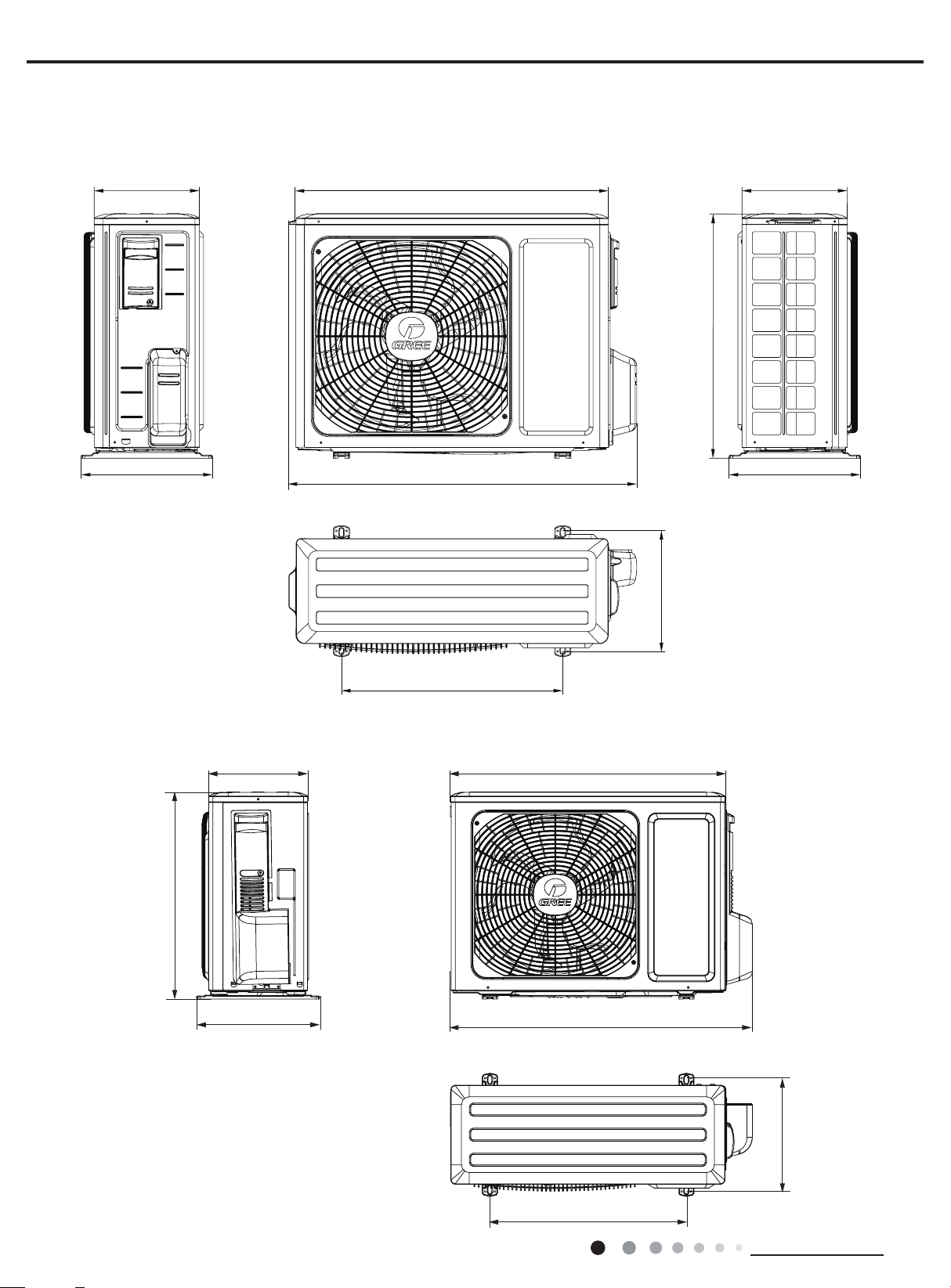
3.2 Outdoor Unit
257
257
780
712
540
GEH12AA-K6DNA1A/O
Service Manual
596
320 320
GEH09AA-K6DNA1F/O
257
848
286
Unit:mm
540
10
320
782
286
Unit:mm Unit:mm
510
Technical Information

Service Manual
892
700
GEH18AA-K6DNA1F/O
341
Unit:mm
396
963
368
560
Technical Information
11
Indoor unit
Outdoor unit
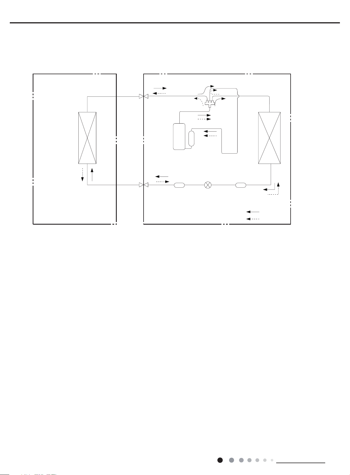
4. Refrigerant System Diagram
Gas pipe
side
Valve
Service Manual
4-Way valve
Discharge
Heat
exchanger
(evaporator)
Connection pipe specication:
Liquid pipe:1/4" (6mm)
Gas pipe:3/8" (9.52mm)(09/12K)
Gas pipe:1/2" (16mm)(18K)
Liquid pipe
side
Valve
Suction
Strainer
Electron
expansion
valve
Heat
exchanger
(condenser)
Strainer
COOLING
HEATING
12
Technical Information
Service Manual
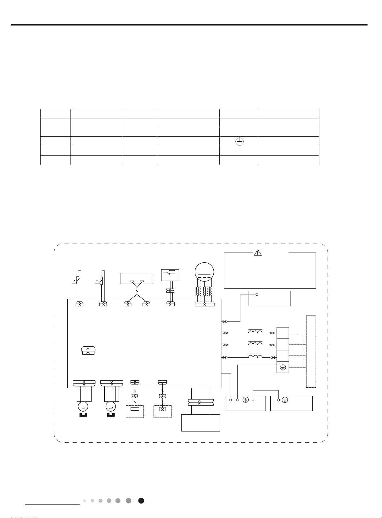
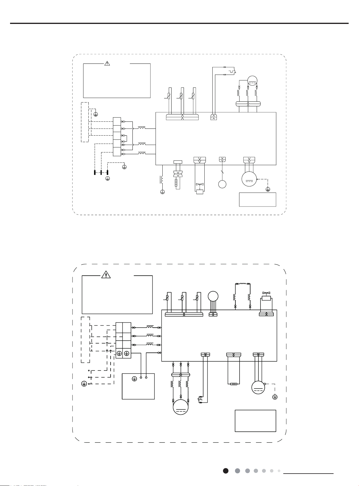
5. Electrical Part
5.1 Wiring Diagram
● Instruction
Symbol Symbol Color Symbol Symbol Color Symbol Name
WH White GN Green CAP Jumper cap
YE Yellow BN Brown COMP Compressor
RD Red BU Blue Grounding wire
YEGN Yellow/Green BK Black / /
VT Violet OG Orange / /
Note: Jumper cap is used to determine fan speed and the swing angle of horizontal lover for this model.
● Indoor Unit
GEH12AA-K6DNA1A/I(CV010N02900) GEH18AA-K6DNA1F/I(CV010N02800)
52207(03
78%(7(03
6(1625
57
57
5220
6(1625
78%(
5(&(,9(5$1'
',63/$<%2$5'
$3
',63/$<
',63
',63
6:,7&+
6(/(&7
6
$3
0$*1(7,&
&1
)$1
0
5,1*
'&02725
02725
$335,17('&,5&8,7%2$5'
&$3
-803
6:,1*'2:1
0
67(33,1*
02725
6:,1*83
0
67(33,1*
02725
:,),
$3
:,),02'8/(
237,21$/
&200$18$/
:,5('
&21752//(5
$3
&20287
$&/
+($/7+/
+($/7+1
&2/'3/$60$
*(1(5$725
237,21$/
3OHDVHGRQWWRXFKDQ\HOHFWURQLF
FRPSRQHQWRUWHUPLQDOZKHQWKH
PDFKLQHLVUXQQLQJVWRSSLQJRU
KDVEHHQSRZHUHGRIIIRUOHVV
WKDQPLQXWHVWRSUHYHQW
HOHFWULFVKRFN
/
02725)5$0(
0$*1(7,&
:$51,1*
&1
1
(
2*
%8
%.
%1
<(*1
5,1*
/
/
/
<(*1
<(*1
%85'
3(
%85'
(9$325$725
(/(&75,&%2;
60000700126803
;7
%8
1
%.
%1
<(*1
7(50,1$/
%/2&.
3(
287'22581,7
Technical Information
13
GEH09AA-K6DNA1F/I(CV010N02701)
Service Manual
52207(03
6(1625
57
5220
&$3
-803
6:,1*'2:1
0
67(33,1*
02725
78%(7(03
6(1625
5(&(,9(5$1'
',63/$<%2$5'
$3
',63/$<
57
78%(
',63
',63
$335,17('&,5&8,7%2$5'
6:,1*83
0
67(33,1*
02725
&1
$3
6
6(/(&7
6:,7&+
&200$18$/
$3
:,5('
&21752//(5
237,21$/
02725
)$1
0
'&02725
&1
1
&20287
$&/
<(*1
(
:,),
$3
:,),02'8/(
237,21$/
3OHDVHGRQWWRXFKDQ\HOHFWURQLF
FRPSRQHQWRUWHUPLQDOZKHQWKH
PDFKLQHLVUXQQLQJVWRSSLQJRU
KDVEHHQSRZHUHGRIIIRUOHVV
WKDQPLQXWHVWRSUHYHQW
HOHFWULFVKRFN
02725)5$0(
:$51,1*
0$*1(7,&
2*
%8
%.
%1
5,1*
/
/
/
;7
1
%8
%.
%1
<(*1
<(*1
7(50,1$/
%/2&.
<(*1
3(
(9$325$725
60000700126801
3(
(/(&75,&%2;
287'22581,7
GEH12AA-K6DNA1A/I(CV010N02901) GEH18AA-K6DNA1F/I(CV010N02801)
52207(03
78%(7(03
6(1625
57
57
5220
6(1625
78%(
5(&(,9(5$1'
',63/$<%2$5'
$3
',63/$<
',63
',63
6:,7&+
6(/(&7
6
$3
0$*1(7,&
&1
)$1
0
5,1*
'&02725
02725
/
&1
&$3
-803
6:,1*'2:1
0
67(33,1*
02725
$335,17('&,5&8,7%2$5'
6:,1*83
0
67(33,1*
02725
:,),
$3
&200$18$/
:,),02'8/(
237,21$/
&21752//(5
$3
:,5('
&20287
$&/
1
(
<(*1
237,21$/
3OHDVHGRQWWRXFKDQ\HOHFWURQLF
FRPSRQHQWRUWHUPLQDOZKHQWKH
PDFKLQHLVUXQQLQJVWRSSLQJRU
KDVEHHQSRZHUHGRIIIRUOHVV
WKDQPLQXWHVWRSUHYHQW
HOHFWULFVKRFN
02725)5$0(
0$*1(7,&
:$51,1*
2*
%8
%.
%1
5,1*
/
/
/
;7
1
%8
%.
%1
<(*1
<(*1
7(50,1$/
%/2&.
<(*1
3(
(9$325$725
60000700126804
3(
(/(&75,&%2;
287'22581,7
14
Technical Information
Service Manual
GEH09AA-K6DNA1F/I(CV010N02700)
52207(03
78%(7(03
6(1625
57
57
5220
&$3
-803
6:,1*'2:1
0
67(33,1*
02725
6:,7&+
6(/(&7
6
6(1625
78%(
5(&(,9(5$1'
',63/$<%2$5'
$3
',63/$<
',63
',63
$335,17('&,5&8,7%2$5'
6:,1*83
0
67(33,1*
02725
:,),
$3
:,),02'8/(
237,21$/
&200$18$/
:,5('
&21752//(5
$3
237,21$/
$3
&1
02725
)$1
0
'&02725
&1
&20287
$&/
+($/7+/
&2/'3/$60$
+($/7+1
%85'
%85'
*(1(5$725
3OHDVHGRQWWRXFKDQ\HOHFWURQLF
FRPSRQHQWRUWHUPLQDOZKHQWKH
PDFKLQHLVUXQQLQJVWRSSLQJRU
KDVEHHQSRZHUHGRIIIRUOHVV
WKDQPLQXWHVWRSUHYHQW
HOHFWULFVKRFN
02725)5$0(
0$*1(7,&
:$51,1*
1
(
2*
%8
%.
%1
<(*1
5,1*
<(*1
/
/
/
<(*1
;7
1
7(50,1$/
%/2&.
3(
(9$325$725
(/(&75,&%2;
600007001268
%8
%.
%1
<(*1
287'22581,7
3(
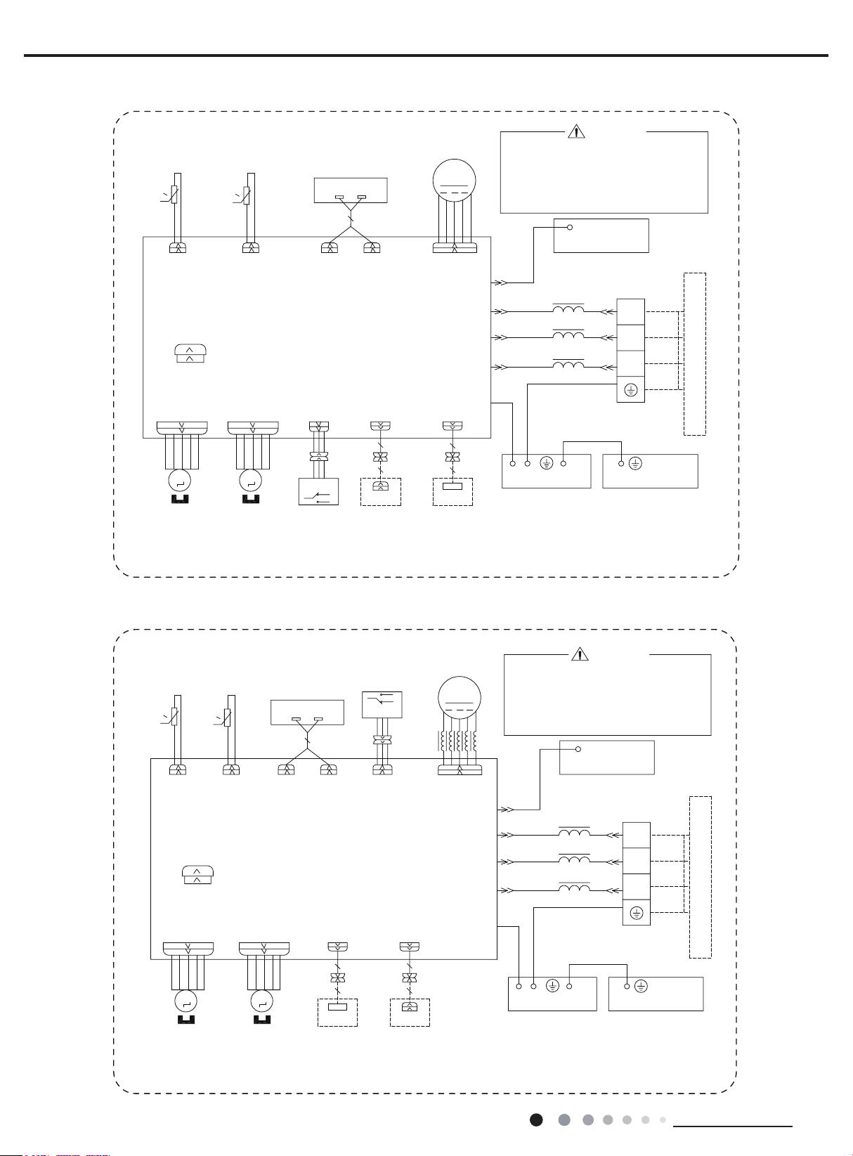
● Outdoor Unit
GEH09AA-K6DNA1F/O
%8
%.
%1
<(*1
%8
%1%.
<(*1
:$51,1*
;7
1
1
/
7(50,1$/
%/2&.
3(
(/(&75,&$/
%2;
N
0$*1(7,&5,1*
<(*1
/
/
/
%8
%.
%1
<(*1
/
/
3OHDVHGRQWWRXFKDQ\
WHUPLQDOZKHQWKHPDFKLQHLV
UXQQLQJVWRSSLQJRUKDVEHHQ
SRZHUHGRIIIRUOHVVWKDQ
PLQXWHVWRSUHYHQWWKHULVN
RIHOHFWULFVKRFN
,1'22581,7
1
/
32:(5
600007061371
2875220
28778%(
7(03
7(03
6(1625
6(1625
57
57
N
1
&208
$&/$&/
3(
8
%8
<(
5,1*
0$*1(7,&
%8
<(
9
8
&203
&203
(;+$867
7(03
6(1625
57
N
&1
$30DLQ%RDUG
:
9
5'
;
/
5'
:
29(5/2$'
3527(&725
(/(&7521,&
(;3$16,21
9$/9(
(.9
0$*1(7,&
&1
29&&203
5'
5'
6$7
5($&725
/
%8
5,1*
/;
%1
/
/
/;
+($7
(+
%RWWRP
%DQG
+HDWHU
127(0RWRU
JURXQGRQO\
DSSOLHVWRWKH
LURQVKHOOPRWRU
97
2)$1
0
)$1
02725
:$<
9$/9(
<9
97
:$<
<(*1
3(
3(
Technical Information
15
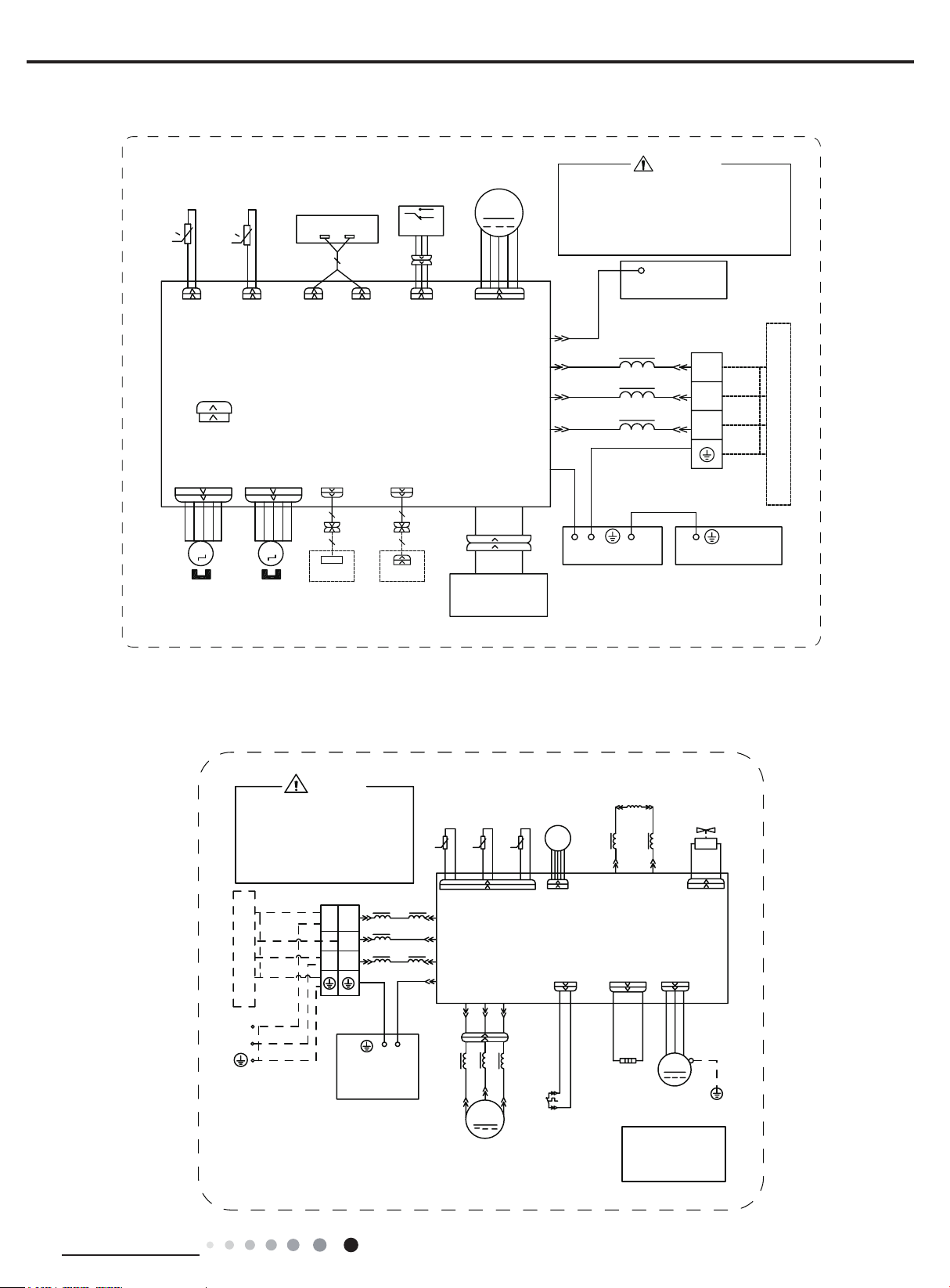
GEH18AA-K6DNA1F/O
Service Manual
3(
%1%.
/1
:$51,1*
7(50,1$/
%/2&.
%8
1
%.
%1
/
%8
1
;7
<(*1
32:(5
%8
%1
0$*1(7,&
3(
5,1*
3OHDVHGRQWWRXFKDQ\
WHUPLQDOZKHQWKHYROWDJH
RIWHUPLQDO3'&DQG
1'&DW$3LVKLJKHU
WKDQ9WRSUHYHQWWKH
ULVNRIHOHFWULFVKRFN
<(*1
,1'22581,7
600007061783
29(5/2$'3527(&725
6$7
&203
7(036(1625
28778%(
2875220
(;+$867
7(036(1625
57 57 57
. ..
:+ %.
/
%.
/
%1
/
%8
<(*1
/
7B6(1625
&20B,11(5
$&B/
1
+($7B%
3(
5'
(+
%27720
%$1'
3(
+($7(5
:$<)$
5'
<9
:$<
9$/9(
:+:+
7(036(1625
0$*1(7,&
5,1*
29&B&203
$3
35,17('&,5&8,7%2$5'
9797
(.9
(OHFWURQLF
([SDQVLRQ
9DOYH
8
&203
9
:
/
/ /
5'
<(%8
<(%8
8%8 9<( :5'
)$102725
1RWH0RWRUJURXQG
RQO\DSSOLHVWRWKH
LURQVKHOOPRWRU
2)$1
0
;
5'
3(
<(*1
3(
GEH12AA-K6DNA1A/O
3OHDVHGRQWWRXFKDQ\
WHUPLQDOZKHQWKHPDFKLQHLV
UXQQLQJVWRSSLQJRUKDVEHHQ
SRZHUHGRIIIRUOHVVWKDQ
PLQXWHVWRSUHYHQWWKHULVN
RIHOHFWULFVKRFN
%8
%.
<(*1
,1'22581,7
%8
1
%1%.
/
<(*1
32:(5
600007061430
%1
:$51,1*
;7
1
1
/
7(50,1$/
%/2&.
3(
(/(&75,&$/
%2;
28778%(
7(03
6(1625
57
N
0$*1(7,&5,1*
/
%8
/
%.
/
%1
<(*1
<(*1
0$*1(7,&
2875220
7(03
7(03
6(1625
57
57
N
N
&1
1
&208
$&/$&/
3(
8
:
9
5'
%8
<(
<(
9
&203
/
5'
:
5,1*
%8
8
&203
(/(&7521,&
(;+$867
(;3$16,21
9$/9(
6(1625
(.9
0$*1(7,&
/;
&1
$30DLQ%RDUG
29&&203
5'
;
6$7
29(5/2$'
3527(&725
+($7
5'
%RWWRP
%DQG
+HDWHU
5($&725
/
/
%1
/
97
%8
5,1*
/;
2)$1
(+
)$1
02725
127(0RWRU
JURXQGRQO\
DSSOLHVWRWKH
LURQVKHOOPRWRU
:$<
9$/9(
:$<
0
<9
97
<(*1
3(
3(
16
These circuit diagrams are subject to change without notice, please refer to the one supplied with the unit.
Technical Information
Service Manual
11 12 13
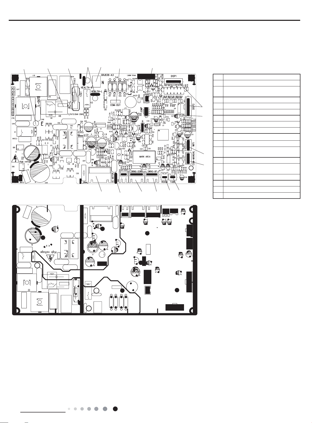
5.2 PCB Printed Diagram
Indoor Unit
● Top view
8
910
● Bottom view
7
14
NO. Name
1 Interface of tube temperature sensor
Interface of ambient temperature
2
sensor
3 Up swing interface
4 Down swing interface
17
5 WIFI interface
16
6 Interface of EMC shielding wire
7 DC motor interface
8 Earthing wire of main board
9 Terminal of live wire
10 Fuse
Terminal for health function
11
5
15
6
34
12
(only for the mode with this function)
12 Terminal of neutral wire
Communication interface between
13
indoor unit and outdoor unit
14 Control interface of Down swing
15 Wired controlled interface
16 Needle stand of jumper cap
17 Interface of display board
Technical Information
17
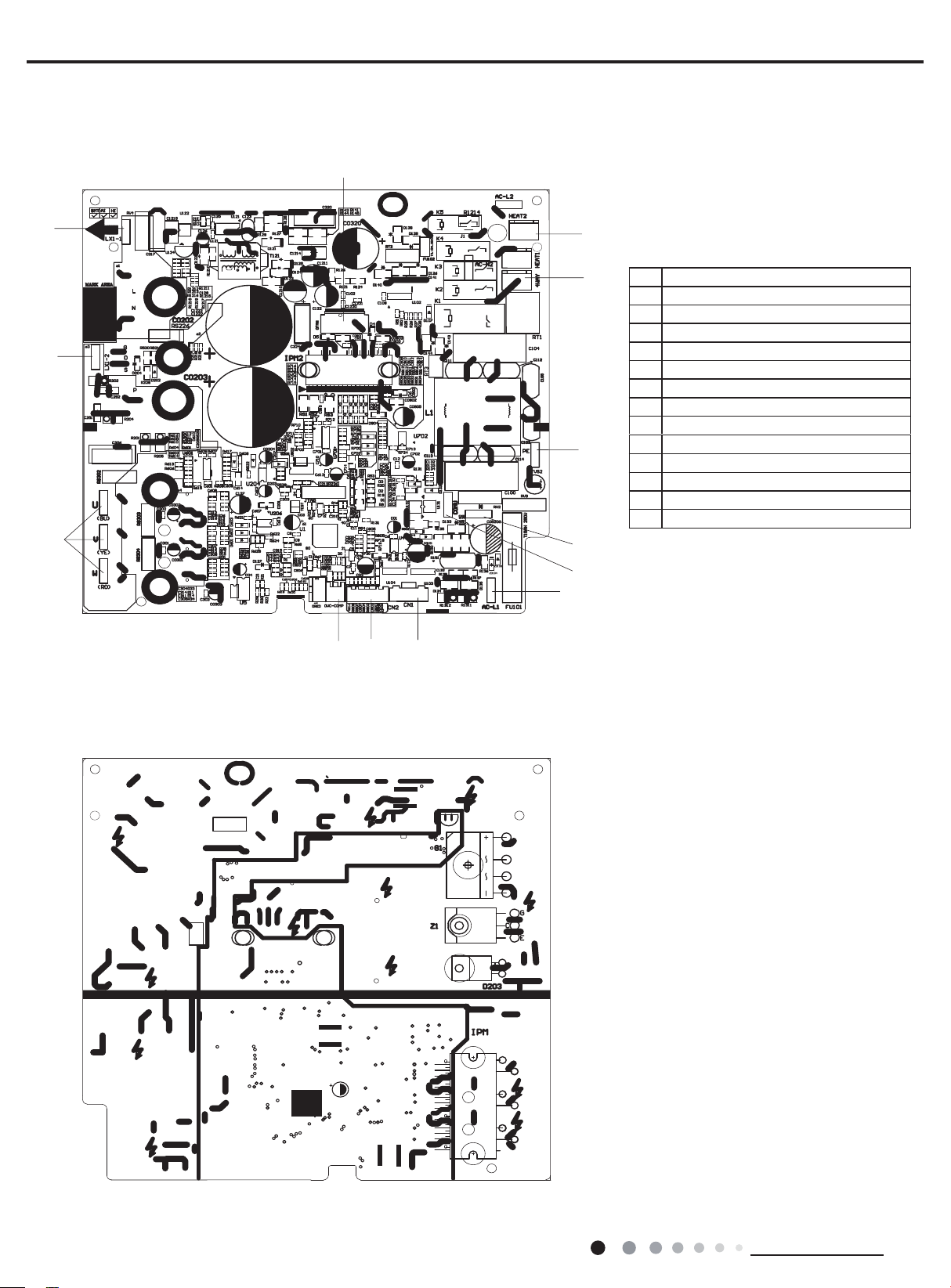
Outdoor Unit
3
● Top view
09/12K
Service Manual
13
2
13
1
4
5
6
No. Name
1 Interface of compressor wire
2 Reactor wiring terminal 2
3 Reactor wiring terminal 1
4 Terminal of chassis electric heater
5
4-way valve terminal
6
Grounding wire
7 Neutral wire
8 Communication wire
Live wire
9
10 Terminal of electronic expansion valve
11 Interface of temperature sensor
12 Overload interface of compressor
Terminal of outdoor fan
13
7
8
9
12
1011
● Bottom view
18
Technical Information
Service Manual
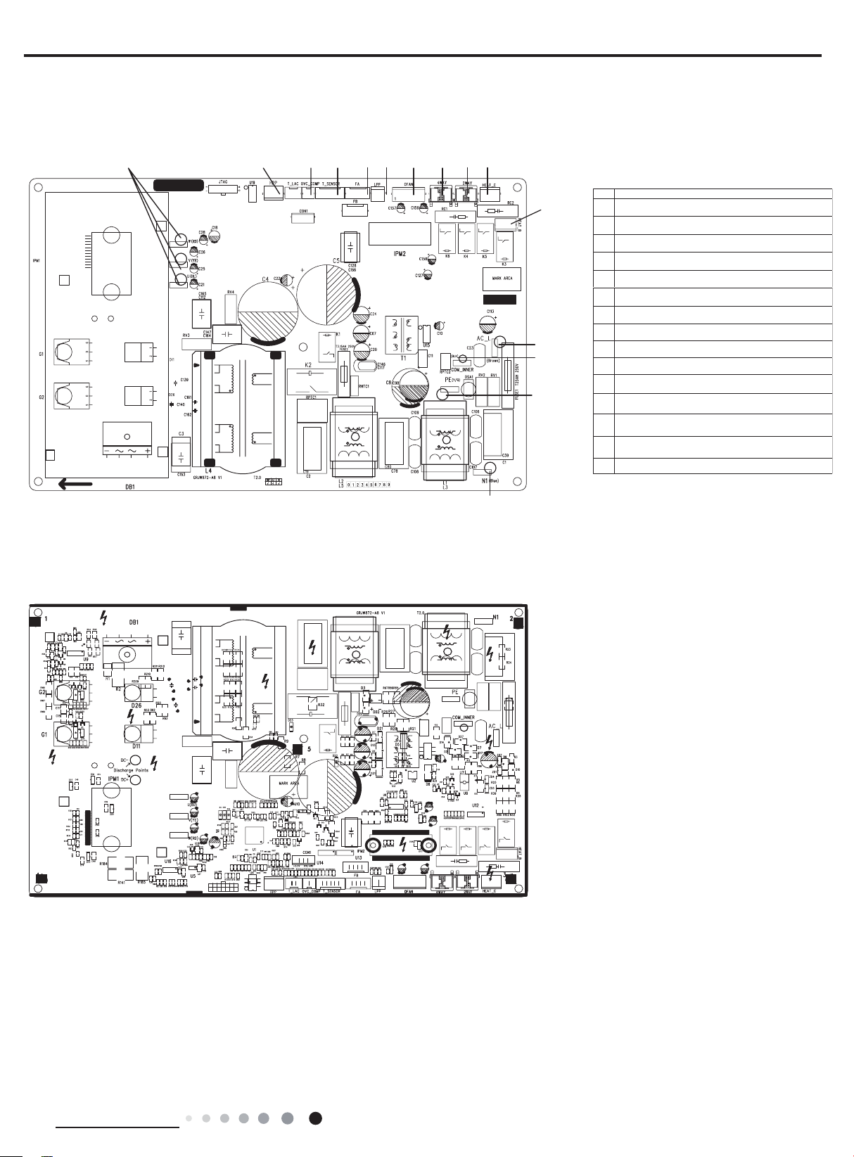
● Top view
GEH18AA-K6DNA1F/O
10
1
2
3
45 78
6
9
No Name
11
1
Compressor wiring terminal for U V W
2Terminal of system high pressure protection
3
Compressor overload protection terminal
4Interface of temperature sensor
5Terminal of electronic expansion valve
67Terminal of system low pressure protection
Terminal of outdoor fan
12
13
14
84-way valve terminal
9Terminal of compressor electric heater
Terminal of compressor electric heater
10
Interface of electric heating belt of chassis
11
Terminal of power supply live wire terminal
12
Interface of communication wire for indoor
13
unit and outdoor unit
14
Terminal of power supply earthing wire
15 Terminal of power supply neutral wire
● Bottom view
15
Technical Information
19
6. Function and Control
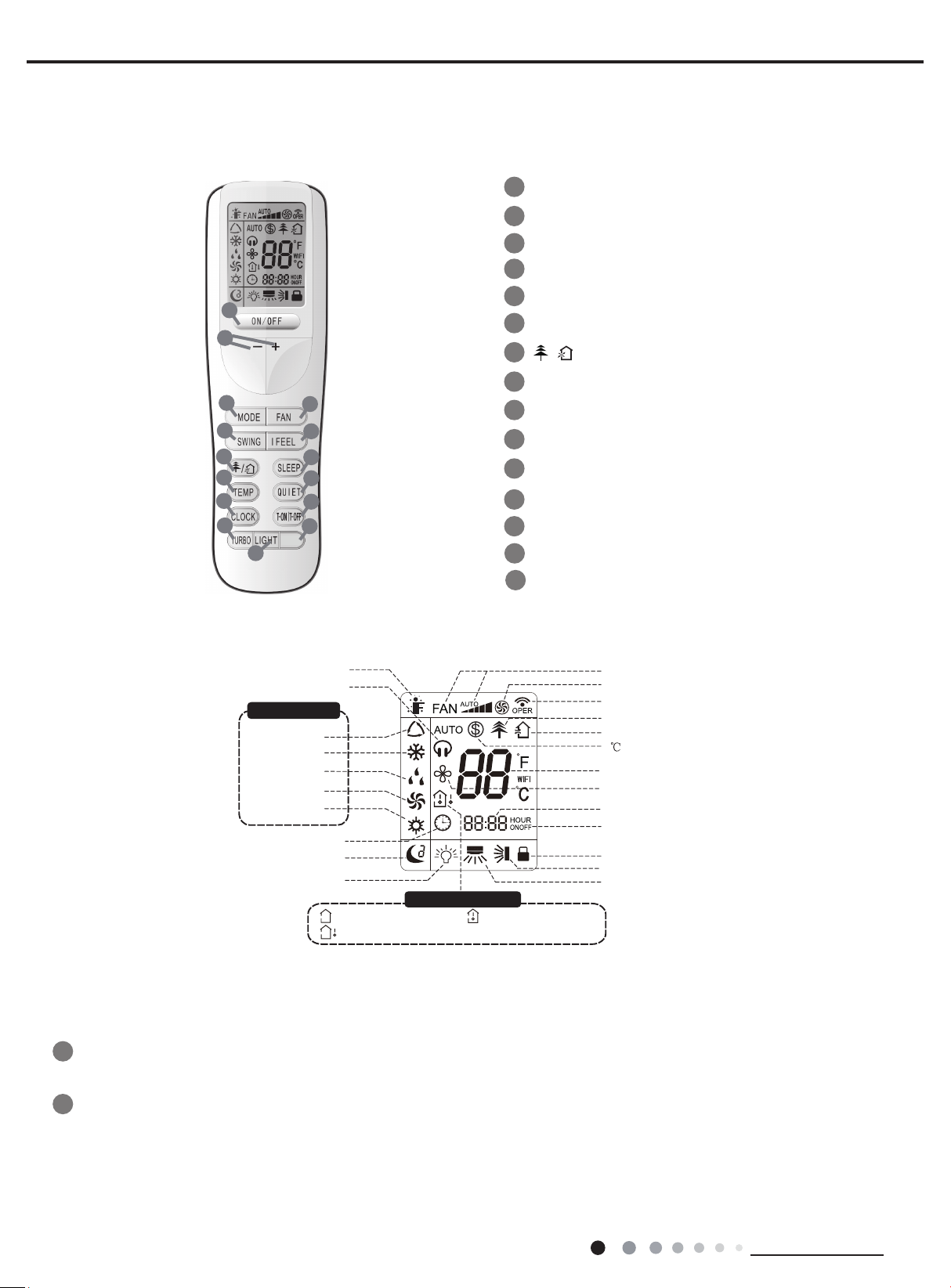
Buttons on Remote Controller
6.1 Remote Controller Introduction
1
2
3
5
7
9
11
13
15
WiFi
4
6
8
10
12
14
ON/OFF button
1
2
+/- button
MODE button
3
4
FAN button
SWING button
5
6
I FEEL button
7
8
SLEEP button
9
TEMP button
10
QUIET button
11
ClOCK button
12
T-ON T-OFF button
13
TURBO button
14
WiFi button
15
button
/
/
LIGHT button
Service Manual
Introduction for Icons on Display Screen
I feel
Quiet
Operation mode
Auto mode
Cool mode
Dry mode
Fan mode
Heat mode
Clock
Sleep mode
Light
Temp. display type
:Set temp.
:Outdoor ambient temp.
:Indoor ambient temp.
Set fan speed
Turbo mode
Send signal
Healthy mode
Scavenging functions
heating function
8
Set temperature
X-FAN function
Set time
TIMER ON /TIMER OFF
Child lock
Up & down swing
Left & right swing
Introduction for Buttons on Remote Controller
Note:
This is a general use remote controller, it could be used for the air conditioners with multifunction; For some function, which the model
doesn't have, if press the corresponding button on the remote controller that the unit will keep the original running status.
ON/OFF button
1
Press this button to turn on the unit. Press this button again to turn off the unit.
20
2
- button
Press this button to decrease set temperature. Holding it down above 2 seconds rapidly decreases set temperature. In AUTO
mode, set temperature is not adjustable.
+ button
Press this button to increase set temperature. Holding it down above 2 seconds rapidly increases set temperature. In AUTO
mode, set temperature is not adjustable.
Technical Information
Service Manual
the
fter
,
Sleep 3- the sleep curve setting under Sleep mode by DIY:
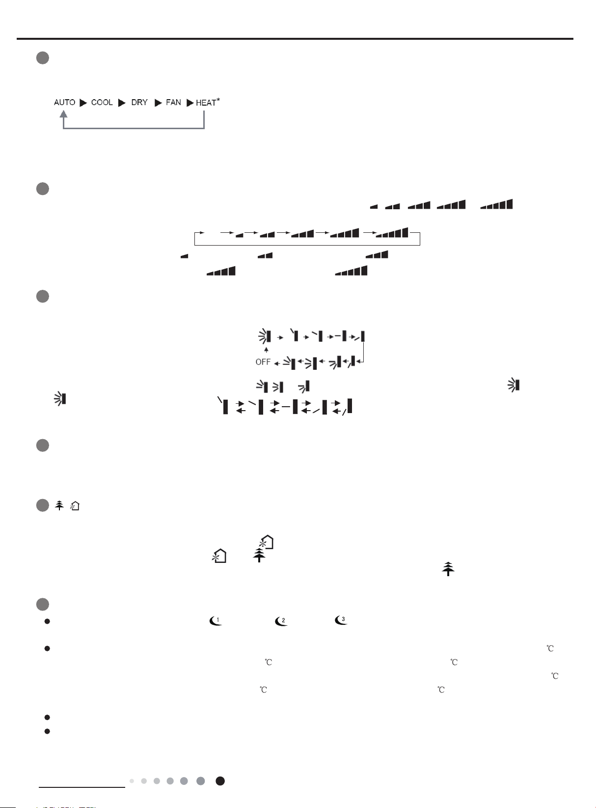
MODE button
3
Each time you press this button , a mode is selected in a sequence that goes from AUTO,COOL, DRY, FAN, and HEAT * , as
following:
*Note:Only for models with heating function.
After energization, AUTO mode is defaulted. In AUTO mode, the set temperature will not be displayed on the LCD, and the unit
will automatically select the suitable operation mode in accordance with the room temperature to make indoor room comfortable.(As
for cooling only unit,it won’t have any action when it receives the signal of heating operation.)
4
FAN button
,
This button is used for setting Fan Speed in the sequence that goes from AUTO, to then back
to Auto.
Auto
SWING button
5
Press this button to set up &down swing angle, which circularly changes as below:
This remote controller is universal. If any command
indicates the guide louver swings as:
, or is sent out, the unit will carry out the command as
,
Medium speedLow-Medium speedLow speed
High speedMedium-High speed
,
,
6
I FEEL button
Press this button to turn on I FEEL function. The unit automatically adjust temperature according to the sensed temperature.
Press this button again to cancel I FEEL function.
7
Press this button to achieve the on and off of healthy and scavenging functions in operation status. Press this button for the
fi rst time to start scavenging function; LCD displays "
functions simultaneously; LCD displays "
functions simultaneously. Press the button for the fourth time to start healthy function; LCD display "
to repeat the operation above.
8
SLEEP button
Press this button, can select Sleep 1 ( ), Sleep 2 ( ),Sleep 3 ( ) and cancel the Sleep,circulate between these, a
electrifi ed, Sleep Cancel is defaulted.
Sleep 1 is Sleep mode 1, in Cool mode: after run for one hour in sleep mode, the main unit setting temperature will increase 1
after 2 hours, the setting temperature will increase 2 , but the maximal setting temperature is 30 , then the unit will run at
this setting temperature all along; In Heat mode: after run for one hour in sleep mode, the setting temperature will decrease 1
after 2 hours the setting temperature will decrease 2 , but the minimal setting temperature is 16 , then the unit will run at this
setting temperature all along.
Sleep 2 is sleep mode 2, that is air conditioner will run according to the presetting a group of sleep temperature curve.
/
button
". Press the button for the second time to start healthy and scavenging
" and " ". Press this button for the third time to quit healthy and scavenging
". Press this button again
Technical Information
21
Service Manual
(1) Under Sleep 3 mode, press "Turbo" button for a long time, remote control enters into user individuation sleep setting status, at this
last
the
y
, the sleep
cedure, press
in
time.
high fan speed.
+ or - button
time, the time of remote control will display "1hour ",the setting temperature "88" will display the corresponding temperature of
setting sleep curve and blink (The fi rst entering will display according to the initial curve setting value of original factory);
(2) Adjust "+" and "-" button, could change the corresponding setting temperature, after adjusted, press "Trubo "button for confi rmation;
(3) At this time, 1hour will be automatically increased at the timer postion on the remote control, (that are "2hours " or "3hours " or
"8hours "), the place of setting temperature "88" will display the corresponding temperature of last setting sleep curve and blink;
(4) Repeat the above step (2)
remote control will resume the original timer display;temperature display will resume to original setting temperature.
Sleep3- the sleep curve setting under Sleep mode by DIY could be inquired:
The user could accord to sleep curve setting method to inquire the presetting sleep curve,enter into user individuation sleep setting
status, but do not change the temperature, press "Turbo" button directly for confirmation.Note: In the above presetting or enquir
procedure,if continuously within10s, there is no button pressed, the sleep curve setting within 10s, there is no button pressed
curve setting status will be automatically quit and resume to display the original displaying. In the presetting or enquiry pro
"ON/OFF" button, "Mode" button, "Timer"button or "Sleep" button, the sleep curve setting or enquiry status will quit similarly.
9
TEMP button
Press this button, you can see indoor set temperature, indoor ambient temperature on indoor unit’s display. The setting on remote
controller is selected circularly as below:
(3) operation, until 8hours temperature setting fi nished,sleep,curve setting fi nished, at this time,
no display
When selecting " " with remote controller or no display, temperature indicator on indoor unit displays set temperature; When
selecting " " with remote controller, temperature indicator on indoor unit displays indoor ambie nt temperature; 5s later or within 5s
it receives other remote control signal that will return to display the setting temperature.
Caution:
This model hasn't outdoor ambient temperature display function. While remote controller
can operate " " and indoor unit displays set temperature.
It’s defaulted to display set temperature when turning on the unit.
Only for the models with temperature indicator on indoor unit.
10
QUIET button
Press this button, the Quiet status is under the Auto Quiet mode (display " "signal )and Quiet mode (display " " singal) and Quiet
OFF (there is no signal of " "displayed),after powered on, the Quiet OFF is defaulted. Note: the Quiet function cannot be set up
Fan and Dry mode;Under the Quiet mode (Display" " Under the Quiet mode) the fan speed is not available.
11
ClOCK button
Press CLOCK button,blinking.
2 seconds increases or decreases the time by 1 minute every 0.5 second and then by 10 minutes every 0.5 second. During blinking
after setting, press CLOCK button again to confi rm the setting, and
12
13
/
T-ON T-OFF button
Press T-ON button to initiate the auto-ON timer. To cancel the auto-timer program, simply press this button again.
After press of this button, disappears and "ON "blink s . 00:00 is displayed for ON time setting. Within 5 seconds, press
to adjust the time value. Every press of either button changes the time setting by 1 minute. Holding down either button rapidly changes
the time setting by 1 minute and then 10 minutes. Within 5 Seconds after setting, press TIMER ON button to confi rm.
Press T-OFF button to initiate the auto-off timer. To cancel the auto-timer program, simply press the button again.TIMER OFF setting is
the same as TIMER ON.
TURBO button
Press this button to activate / deactivate the Turbo function which enables the unit to reach the preset temperature in the shortest
In COOL mode, the unit will blow strong cooling air at super high fan speed. In HEAT mode, the unit will blow strong heating air at super
Auto
Within 5 seconds, pressing + or - button adjusts the present time. Holding down either button above
then will be constantly displayed.
22
Technical Information
Service Manual
s
14
WiFi button
Press " WiF "i button to turn on or turn off WiFi function. When WiFi function is turned on, the " W i F i " icon will be displayed on remote
controller; Under status of unit off, press "MODE" and "W i F i " " buttons simultaneously for 1s, WiFi module will restore to factory
default setting.
● This function is only available for some models.
15
LIGHT button
Press LIGHT button to turn on the display's light and press this button again to turn off the display 's light. If the light is turned on , i
displayed. If the light is turned of
If “H1” is displayed on the remote controller while it’s not operated by the professional person/after-sales person, it belongs to the
misoperation.
Please operate it as below to cancel it.Under the OFF status of remote controller, hold the Mode button for 5s to cancel “H1” display.
Note:
● If remote controller displays “H1”, it belongs to the normal function reminder. If the unit is defrosting under heating mode, it operates
according to H1 defrosting mode. “H1” won’t be displayed on the panel of indoor unit;
● Once you set H1 mode, if you turn off unit by remote controller, H1 will display 3 times on the remote controller and then disappear;
● Also, when you set H1 mode, when you change to heating mode, H1 will display 3 times on the remote controller and then disappear.
Combination of "+" and "-" buttons: About lock
Press "+" and "-" buttons simultaneously to lock or unlock the keypad. If the remote controller is locked,
pressing any button,
Combination of "MODE" and "-" buttons:About switch between Fahrenheit and centigrade
At unit OFF, press "MODE" and "-" buttons simultaneously to switch between °C and °F.
Combination of "TEMP" and "CLOCK" buttons:About Energy-saving Function
Press "TEMP" and "CLOCK" simultaneously in COOL mode to start energy-saving function.Nixie tube on the remote controller displays
"SE". Repeat the operation to quit the function.
Combination of "TEMP" and "CLOCK" buttons:About 8°C Heating Function
Press "TEMP" and "CLOCK" simultaneously in HEAT mode to start 8°C Heating Function Nixie tube on the remote controller displays
" and a selected temperature of "8°C".(46°F if Fahrenheit is adopted). Repeat the operation to quit the function.
"
About Back-lighting Function
The unit lights for 4s when energizing for the
blinks three times.
f, disappears.
is displayed. In this case,
fi rst time, and 3s for later press.
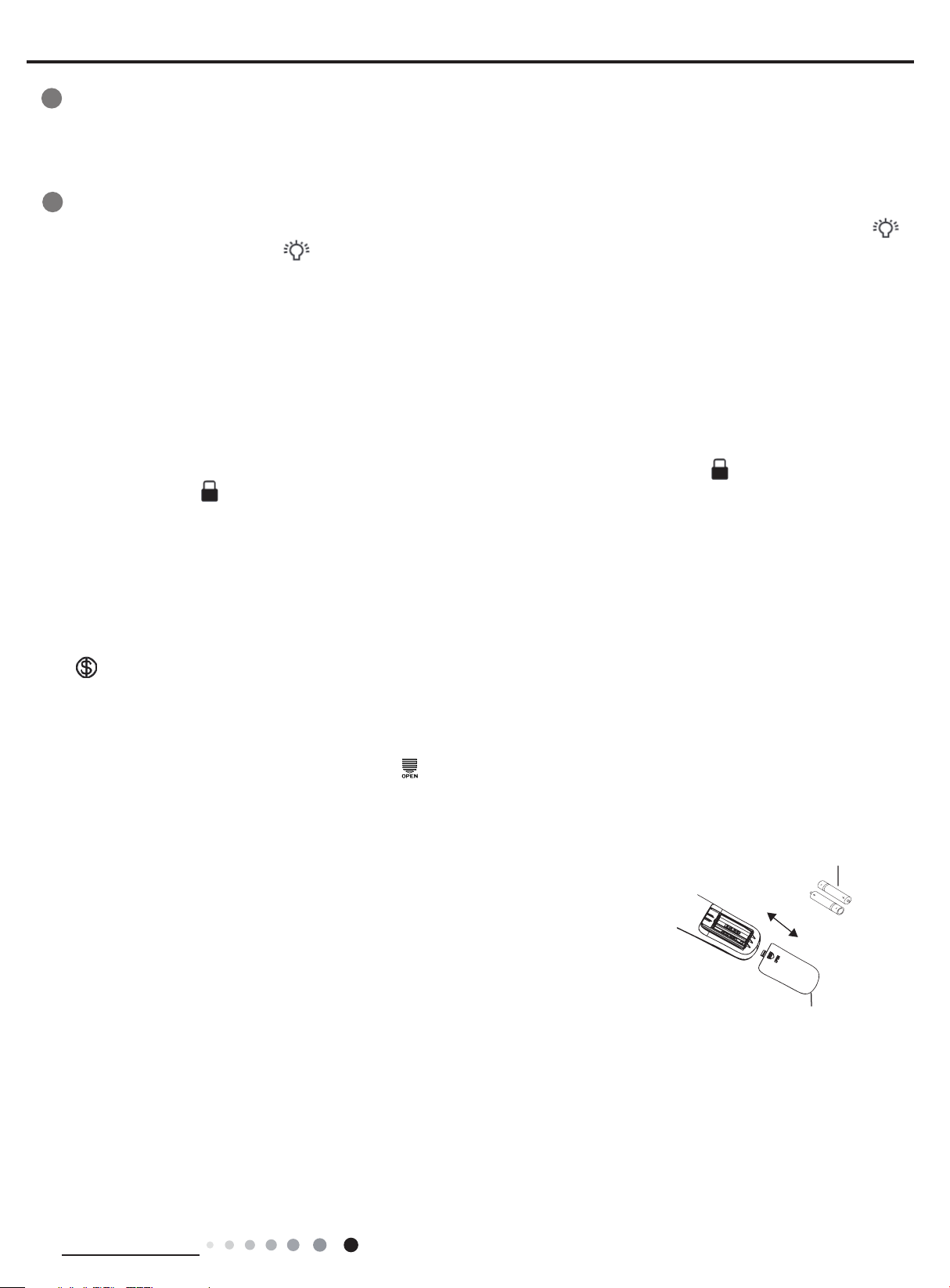
Replacement of Batteries in Remote Controller
1.Press the back side of remote controller marked with“
of battery box along the arrow direction.
2. Replace two 7# (AAA 1.5V) dry batteries, and make sure the position of “+” polar and “-“ polar are correct.
3. Reinstall the cover of battery box.
Note:
● During operation, point the remote control signal sender at the receiving window
on indoor unit.
● The distance between signal sender and receiving window should be no more than
8m, and there should be no obstacles between them.
● Signal may be interfered easily in the room where there is fluorescent lamp or
wireless telephone; remote controller should be close to indoor unit during operation.
● Replace new batteries of the same model when replacement is required.
● When you don’t use remote controller for a long time, please take out the batteries.
● If the display on remote controller is fuzzy or there’s no display, please replace
batteries.
”as shown in the fi g, and then push out the cover
battery
reinstall
remove
Cover of battery box
Technical Information
23
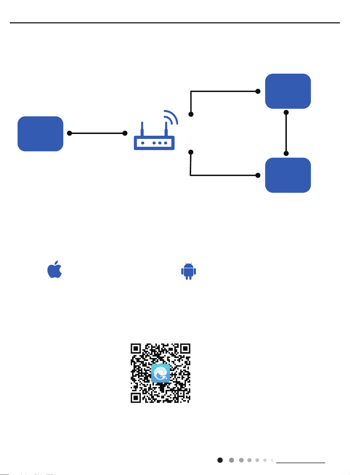
6.2 GREE+ App Operation Manual
iOS system
Android system
and
GREE+ App Download Linkage
Control Flow Chart
Service Manual
Internet
Gree Cloud
Gree
intelligent
Home Wi-Fi
home
appliances
Operating Systems
Requirement for User's smart phone:
Support iOS7.0 and
above version
Cellular/
Other Wi-FI
Home wireless router
Home Wi-Fi
GREE+ APP
Support Android 4.4
above version
Download and installation
Scan the QR code or search "GREE+" in the application market to download and install it. When "GREE+" App is installed, register the
account and add the device to achieve long-distance control and LAN control of Gree smart home appliances.
For more information, please refer to "Help" in App.
24
Technical Information
Service Manual
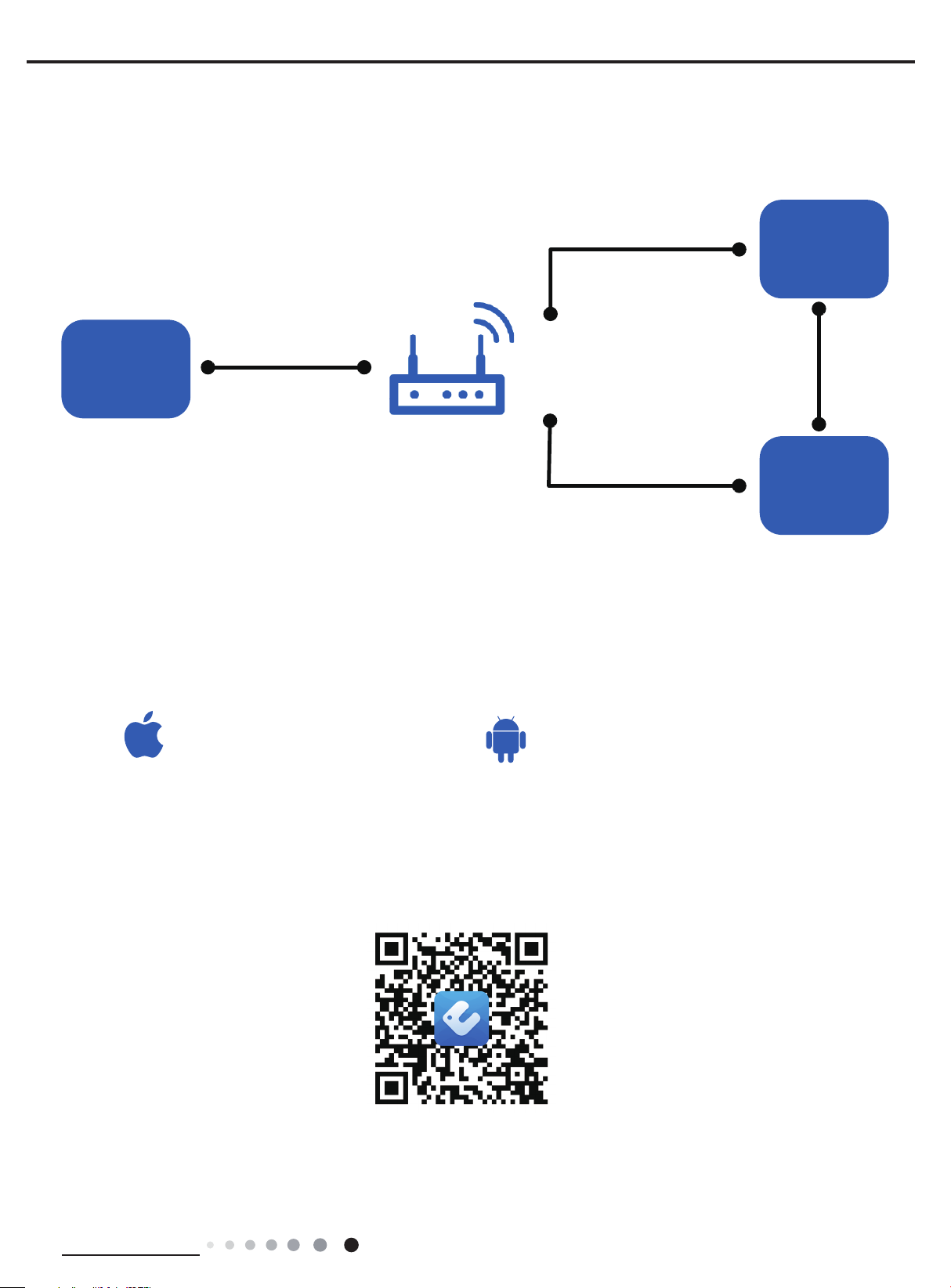
iOS system
Android system
and
6.3 Ewpe Smart App Operation Manual
Control Flow Chart
Internet
Cloud
intelligent
Home Wi-Fi
home
appliances
Operating Systems
Requirement for User's smart phone:
Support iOS7.0 and
above version
Cellular/
Other Wi-FI
Home wireless router
Home Wi-Fi
APP
Support Android 4.4
above version
Download and installation
App Download Linkage
Scan the QR code or search "Ewpe Smart" in the application market to download and install it. When "Ewpe Smart" App is installed,
register the account and add the device to achieve long-distance control and LAN control of smart home appliances.
For more information, please refer to "Help" in App.
Technical Information
25

Service Manual
6.4 Brief Description of Modes and Functions
1. Cooling mode
(1) Under this mode, the fan and the up swing will operate at setting status. The temperature setting range is 16~30ºC.
(2) The unit is stopped because of malfunction of outdoor unit or protection. The indoor unit keeps original operation status and the
error code is displayed.
(3) Indoor unit is stopped due to mode shock.
2. Drying mode
(1) Under this mode, the fan operates at low speed and the swing operates at setting status. The temperature setting range is
16~30ºC.
(2) The unit is stopped because of malfunction of outdoor unit or protection. The indoor unit keeps original operation status and the
error code is displayed.
3. Heating mode
(1) Under this mode, the temperature setting range is 16~30ºC.
(2) Working condition and process for heating
When the unit is turned on under heating mode, the indoor unit turns to cold air prevention status. When the unit is turned off and the
indoor unit has been started up before, the indoor unit blows the residual heat.
(3) Protection function: When the compressor is stopped due to malfunction under heating mode, the indoor unit blows the
residual heat.
(4) Blow residual heat
When the unit stops operation as it reaches the temperature point, indoor unit will continue to run for 60s. The fan speed cant be
switched during blowing residual heat period. The upper horizontal louver will turn to the defaulted position in cooling. When the unit
operates under heating mode or auto heating mode, compressor will be turned on and the corresponding electric expansion valve is
more than 65 and the unit stops operation during the operation status of indoor unit. The upper horizontal louver will turn to the
defaulted position in heating mode. The indoor unit operates at low speed for 10s and then the unit stops operation.
(5) Defrosting, oil-returning
As it received the signal of defrosting and oil-returning from outdoor unit, the upper horizontal louver will turn to the minimum angle in
cooling. 10s later, the in door fan stop operation. During defrosting and oil-returning process and they are quitted within 5mins, all
malfunctions for indoor tube temperature sensor wont be detected.
4. Working process for AUTO mode (Mode judgment will be performed every 30s)
Under AUTO mode, standard cooling Tpreset=25ºC (77ºF), standard heating Tpreset=20ºC (68ºF), and standard fan Tpreset= 25ºC
(77ºF).
(1) When Tamb≥26ºC (79ºF), the unit operation in cooling mode;
(2) Heating pump unit: When Tamb≤19ºC (66ºF), the unit operates in heating mode;
(3) Cooling only unit: Tamb≤19ºC (66ºF), the unit operates in fanmode;
(4) When 19ºC<Tindoor amb.<26ºC, if it turns to auto mode as the unit is turned on for the rst time the unit will operates at auto fan
mode. If it switch to auto mode from other modes, the unit will keep previous operation mode (when it turns to dry mode, the unit
operates at auto fan mode).
(5) Protection function
Protection function is the same as that in cooling or heating mode.
5. Fan mode
Under fan mode, only indoor fan and swing operates. When it operates at auto fan speed, it will operate according to auto fan speed
condition in cooling.
6. Mode shock
If the mode shock is 1 which is received by indoor unit from outdoor unit, the loads of indoor unit (indoor unit, auxiliary heating,swing)
stop operation and the error code is displayed. The mode sent to outdoor unit is still remote control receiving mode. The unit will be
turned off during mode shock.
If timer ON is reached, and the mode shock is 1 which is received by indoor unit from outdoor unit, the loads of indoor unit (indoor
unit,auxiliary heating, swing) stop operation and the error code is displayed. The mode sent to outdoor unit is still remote control receiving
mode.
7. Other control
7.1 Buzzer
Upon energization or availably operating the unit or remote controller, the buzzer will give out a beep.
7.2 Auto button
If this button is pressed, the unit will operate in AUTO mode and indoor fan will operate at auto speed; meanwhile, the swing motor
operates. Press this button again to turn off the unit.
7.3 8 ºC heating function
Under heating mode, press TEMP+CLOCK buttons simultaneously. Under this mode, “cold air prevention protection” will be shielded.
26
Technical Information

Service Manual
7.4 I FEEL function
When I FEEL command is received, the controller will operate according to the ambient temperature sent by the remote controller (For
defrosting and cold blow prevention, the unit operates according to the ambient temperature sensed by the air conditioner). The
remote controller will send ambient temperature data to the controller every 10min. When the data has not been received after
11mins,the unit will operate according to the temperature sensed by the air conditioner. If I FEEL function is not selected, the ambient
temperature will be that sensed by the air conditioner. I FEEL function will not to be memorized.
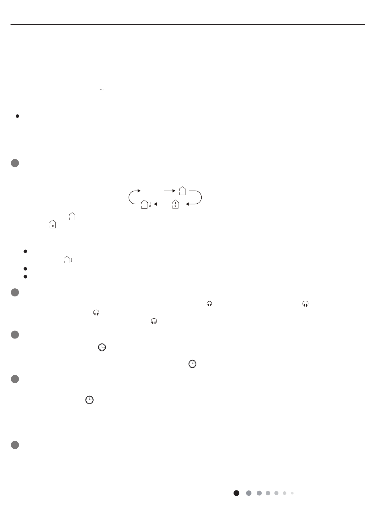
7.5 Timer function
General timer and clock timer functions are compatible by equipping remote controller with different functions.
(1)General Timer
Timer ON can be set at unit OFF. If selected ON time is reached, the unit will start to operate according to previous setting status.
Time setting range is 0.5-24hr in 30-minute increments.
Timer OFF can be set at unit ON. If selected OFF time is reached, the unit will stop operation. Time setting range is 0.5-24hr in
30-minute increments.
(2)Clock Timer
Timer ON
If timer ON is set during operation of the unit, the unit will continue to operate. If timer ON is set at unit OFF, upon ON time reaches
the unit will start to operate according to previous setting status.
Timer OFF
If timer OFF is set at unit OFF, the system will keep standby status. If timer OFF is set at unit ON, upon OFF time reaches the unit
will stop operation.
Timer Change
Although timer has been set, the unit still can be turned on/off by pressing ON/OFF button of remote controller. You can also set
the timer once again, and then the unit will operate according to the last setting. If timer ON and timer OFF are set at the same time
during operation of the unit, the unit will keep operating at current status till OFF time reaches. If timer ON and timer OFF are set at
the same time at unit OFF, the unit will keep stop till ON time reaches. In the future’s every day, the system will operate according to
presetting mode till OFF.
7.6 Sleep function
This mode is only valid in cooling and heating modes. The unit will select proper sleep curve to operate according to different set
temperature.
7.7 Compulsory defrosting function
When the unit is turned on in heating by remote controller and the set temperature is 16oC, press “+,-,+,-,+,-”continuously within 5s,
the indoor unit turns to compulsory defrosting setting and it will send compulsory defrosting mode to outdoor unit.
When indoor unit received the compulsory defrosting signal from outdoor unit, the indoor unit will quit from the compulsory defrosting
setting and it will cancel to send compulsory defrosting mode to outdoor unit.
7.8 Refrigerant recovery function
Turn to Freon recovery mode: After the unit is energized for 5min, and the unit is turned on at 16ºC under cooling mode, press light
button on remote controller for 3 times successively within 3s to turn to Freon recovery mode. Fo is displayed and it will send Freon
recovery mode to outdoor unit.
Quit from Freon recovery mode:After it turns to Freon mode, if it receives any signal from remote controller or it turns to Freon
recovery mode for 25 mins, it will quit from Freon recovery mode.
Turn to the action for Freon recovery mode: indoor unit will be turned on in cooling mode. The fan speed is super-high fan speed and
the set temperature is 16oC. The horizontal louver will turn to the minimum operation angle.
Quit the action for Freon recovery mode: The indoor fan operates at the previous set status by remote controller.
7.9 Pilot run function
When the set temperature is 30oC under cooling mode, press “+,-,+,-,+,-”continuously within 5s, the indoor unit turns to pilot run
setting mode and it will send pilot run mode to outdoor unit.
Pilot run mode: it operates under cooling mode and “dd” is displayed.
Quit the pilot run mode and indoor unit cancels “dd” display. If it receives “wrong wire connection of malfunction of expansion valve”
from outdoor unit, “dn” will be displayed.
Technical Information
27
 Loading...