

Gree GAE09AB-D3RNB1A, GAA09AB-D3RNB1A, GAE12AB-D3RNB1A, GAA15AB-D3RNB1A, GAA12AB-D3RNB1A Owner's Manual
...
PACKAGED TERMINAL
AIR CONDITIONER
OWNER’S MANUAL
Please read this manual carefully before running the unit.
Thank you for choosing a GREE air conditioner. Please read this owner's manual
carefully before operating the unit and keep it handy for future reference.
0
0510-14/07/11
©
Copyright, Sunrise Tradex Corp., 2011
MODELS:
13-04690 / GAE09AB-D3RNB1A
13-04704 / GAA09AB-D3RNB1A
13-04691 / GAE12AB-D3RNB1A
13-04705 / GAA12AB-D3RNB1A
13-04692 / GAE15AB-D3RNB1A
13-04706 / GAA15AB-D3RNB1A
WWW.GREE.CA
St-Mathieu-de-Beloeil (Québec) Canada
1-866-680-GREE
CONTENTS
The figures in this manual may differ from the
actual objects. Please refer to the actual objects
for reference.
This symbol represents the instructions that must
be followed.
The figures in this manual may differ from the actual objects. Please refer to the actual objects for reference.
D
o not dispose of this product as unsorted municipal waste.
This product must be disposed of separately for special processing.
1. SAFETY CONSIDERATIONS ...................................................................................................... 1
2. GENERAL INFORMATION ........................................................................................................ 1
3. UNIT FEATURES .................................................................................................................. 2
4. ELECTRICAL DATA ................................................................................................................ 4
5. INSTALLATION .................................................................................................................... 5
6. HOW TO CONNECT ................................................................................................................ 8
7. SYSTEM CONFIGURATION ...................................................................................................... 9
8. AUXILIARY CONTROLS .......................................................................................................... 12
9. OPERATION ........................................................................................................................ 14
10. CARE AND CLEANING .......................................................................................................... 15
11. PREVENTATIVE MAINTENANCE .............................................................................................. 16
12. TROUBLESHOOTING ............................................................................................................ 17
13. WARRANTY ...................................................................................................................... 18
1
GREE packaged terminal air conditioners and heat pumps provide high quality performance, workmanship, durability and
appearance, as they heat and cool the living space year round. This manual provides information for installation, operation and
maintenance. All models are designed for wall-embedded installation. Separate installation instructions are included with all
accessory components.
Read all the instructions carefully.
IMPORTANT: Save these instructions for the local inspectorʼs use.
IMPORTANT: Observe all governing codes and ordinances.
Be sure to leave these instructions with the owner.
Keep these instructions for future reference. Be sure to write down the model and serial number of the unit on the space
provided on the back page. The model and serial number can be located on the serial number plate attached to unit. These
numbers are required for service. (See Fig. 1.)
NOTE: We strongly recommend that any servicing be performed by a qualified individual.
BEFORE YOU BEGIN
NOTE TO INSTALLER
NOTE TO OWNER
SAFETY CONSIDERATIONS
GENERAL INFORMATION
WARNING
PERSONAL INJURY AND/OR PROPERTY DAMAGE HAZARD
Failure to follow this warning may result in personal injury, death and/or property damage.
For your safety, the information in this manual must be followed to minimize the risk of fire or explosion, electric shock, or
to prevent property damage, personal injury, or loss of life.
• This unit must be properly installed in accordance with the Installation Instructions before it is used.
• Immediately repair or replace all electric service cords that have become frayed or otherwise damaged.
• Unplug or disconnect the unit at the fuse box or circuit breaker before making any repairs.
This is the safety-alert symbol .When you see this symbol on the unit and in instructions or manuals, be aware that there is
the potential for personal injury.
Understand these signal words: DANGER, WARNING, and CAUTION. These words are used with the safety-alert symbol.
• DANGER identifies the most serious hazards that will result in severe personal injury or death.
• CAUTION is used to identify unsafe practices that may result in minor personal injury or product and property damage.
• NOTE is used to highlight suggestions that make the unit easier to install or operate, or that make the unit more reliable.
G
REE ELECTRIC APPLIANCES
WWW.GREE.CA
MODEL #
S
ERIAL #
L
ISTED 3JNY
PACKED TERMINAL AIR CONDITIONER
W
arni ng: Use on Sin gl e Outlet C i r cuit Onl y.
A
lso Verified In Accordance With Energy
S
tandards DDE Test Procedure
10 CFR, Part 430, App. F, Issued 01/01
and CAN/CSA-C368,1-M90
D
ESIGN PRESSURE LOWSIDE 300 P.S.I.
R
ATED VOLTS 1 PHASE 60 HZ
EER COP R410a Z. MFG.DATE
COOLING ELECTRIC HEATING HEATING
BTU/HR BTU/HR BTU/HR
AMPS AMPS AMPS
WATTS WATTS WATTS
F
ig. 1 – Sample data information plate
UNIT FEATURES
2
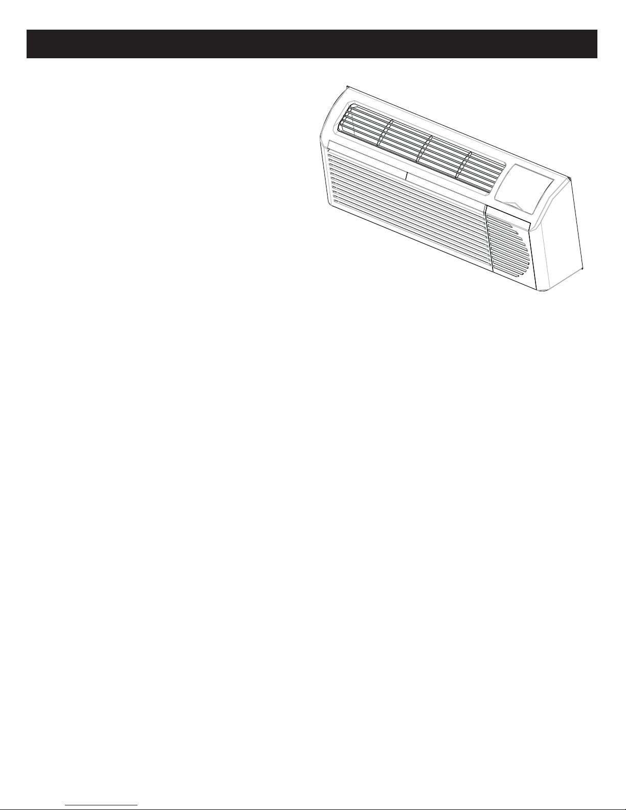
This premium unit has many exciting features that differ from
those of most standard PTAC models. The owner must be
familiar with these features in order to fully understand the
operation and capability of the unit.
• Intelligence – Your premium unit has a computer that
utilizes real-time diagnostics to prolong the life of your unit.
There is a LED indicator on the control board, behind the
front panel, that flashes an error code if the unit detects a
malfunction. In many cases, the unit automatically clears the
malfunction and continues operating without interruption. In
some cases, the malfunction cannot be cleared and the unit
requires service. In those cases, an “Fx” failure mode will
appear on the digital display. For a detailed list of all error
codes and “Fx” conditions, see Table 6 – Status LED
Indicator Definitions.
• Memory – Your premium unit also has memory. If power is
lost, all of the control settings (setpoint temperature, mode,
fan speed, on/off and configuration) are remembered. So when power is restored, the unit will start back up in the mode
(and configuration) it was in when power was lost.
• Premium sound – Not only does the unit have two fan motors and a tangential blower wheel for optimum sound control, the
indoor fan always runs at least 10 seconds before the compressor starts, to help reduce noise from when the compressor starts.
• Random compressor restart – To help prevent power surges after a power outage (from several PTACs starting at the same
time), the compressor is equipped with a 2:45 to 3:15 random restart delay feature. Whenever the unit is plugged in, or the power
has been restarted, a random compressor restart will occur.
• Compressor protection – To prevent the compressor from short cycling and to maximize its life, there is a random start-up
delay of three minutes on the compressor and a minimum compressor run time of three minutes.
•Automatic freeze protection – Automatically keeps the room temperature from getting too cold, when water pipes might
freeze. If the unit is configured for freeze protection ( the default condition), then whenever power is supplied to the unit, if the
unit senses that the temperature is below 40°F, the fan motor and electric heater turn on and warm the room to 50°F. If freeze
protection is not required, change the configuration switch to turn the feature off (see section on unit configuration).
• Automatic defrost protection (for heat-pump models only) – When the outdoor temperature gets too cold (approx. 35°F)
and the unit can no longer effectively heat with the compressor, the unit automatically switches to electric heating. The unit then
heats with electric heat until the outside temperature rises enough (approx. 40°F) for the compressor to be used again.
• Automatic quick warm-up (for heat pump models only) -- If the room temperature falls to 5°F below the set temperature, the
reverse-cycle heat turns off and the electric strip heat turns on for one cycle, until heating is satisfied.
•LED indicators and buttons – The touch pad has buttons for MODE, FANSPEED, ON/OFF,
SETPOINT UP and SETPOINT DOWN. It also has LED lights that correspond to the mode, fan speed and setpoint operation,
to indicate the unitʼs status. The LED lights below MODE, FAN, COOL, and HEAT, indicate the active operating mode. The LED
lights below the Fan button, Low, Med and Hi, indicate the selected fan speed. The LED light located in the lower right corner
shows whether the unit is on or off. If the unit is ON, the LED will be green. If the unit is OFF, the LED will be red.
• Configure fan to optimize selected application – The unit can optimize a selected application by configuring the fan to run
in continuous mode or to cycle on and off with the compressor and electric heater (can be different for both heating and cooling
modes). In cycle mode, the fan continues to run after the compressor or electric heater stops in order blow out any residual heat
or cool left in the coil.
Fig. 2
UNIT FEATURES CONTINUED
3
• Unit configuration – There are many different possible configurations, set with both DIP switches and the digital keypad, that
allow you to configure the unit for your exact needs. See the section on unit configuration for more details. The following are the
configuration selections that have not previously been mentioned:
• °F or °C – The unit can display temperatures in either °F or °C.
• Indoor temperature sensor biasing – Optimize the room temperature sensor reading to your exact needs (one for cooling
and another for heating).
• Emergency heat (for heat pump only) – Disable the compressor while the heat mode is running (heat only with electric heat).
• Display setpoint OR room temperature – The unit can be configured to display the room temperature OR the setpoint temperature
only, in the heat and cool modes. See section on unit configuration for more details.
• Limit the setpoint range – The unit can be configured to limit the setpoint range. The display will always show the complete
setpoint range, but the controlled setpoint will be limited to the selected minimum and maximum setpoint. See section on unit
configuration for more details.
• Energy management – Also known as Front Desk Control, an input is provided so that the unit can be manually disabled from
a different location. If the unit detects 24 VAC from this input, it automatically turns itself off. If no voltage is detected from the
input, the unit runs normally.
• Wall thermostat control – A wired wall thermostat can be connected to the unit. If this is done, the unit must be configured to
disable the keypad. See section on wired inputs and unit configuration for more details.
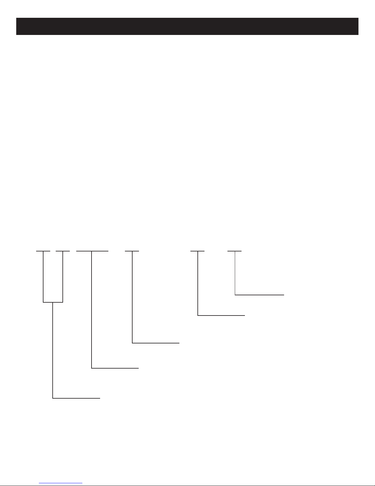
G A E (A) 07 A B - D (P) 3 RNB1A
P
TAC / TTW
Cooling capacity
Refrigerant R410a
Voltage D 230 / 208 ~ 60Hz
P 265V ~ 60Hz
E Electrical + cooling
A Electrical + heat pump
Fig. 3 – Catalog number nomenclature
ELECTRICAL DATA
4
• POWER CONNECTION OPTIONS
• ALL UNITS
• VOLTAGE SUPPLY
WARNING
ELECTRICAL SHOCK HAZARD
Failure to follow this warning could result in personal injury or death and/or property damage.
DO NOT alter cord or plug. DO NOT use an extension cord.
The appropriate power cord accessory kit is determined by the voltage and amperage of the branch circuit.
The unit does not come with a power cord (or hard wire kit). A power cord accessory kit must be ordered to connect the
unit to the outlet. If the unit is to be hard wired, a hard wire accessory kit must be ordered.
LEGEND
AWG --- American Wire Gauge
* Single circuit from main box.
† Based on copper wire at 60°C temperature rating.
Table 1—SUGGESTED BRANCH CIRCUITWIRE SIZES*
Wire size
Use the recommended wire size provided in Table 1 and install a single branch circuit. All wiring must comply with local
and national codes. All units are designed to operate from ONE single branch circuit only.
Grounding
For safety and protection, the unit is grounded through the power cord plug or through a separate ground wire provided on
hard-wired units. Be sure that the branch circuit or general purpose outlet is grounded.
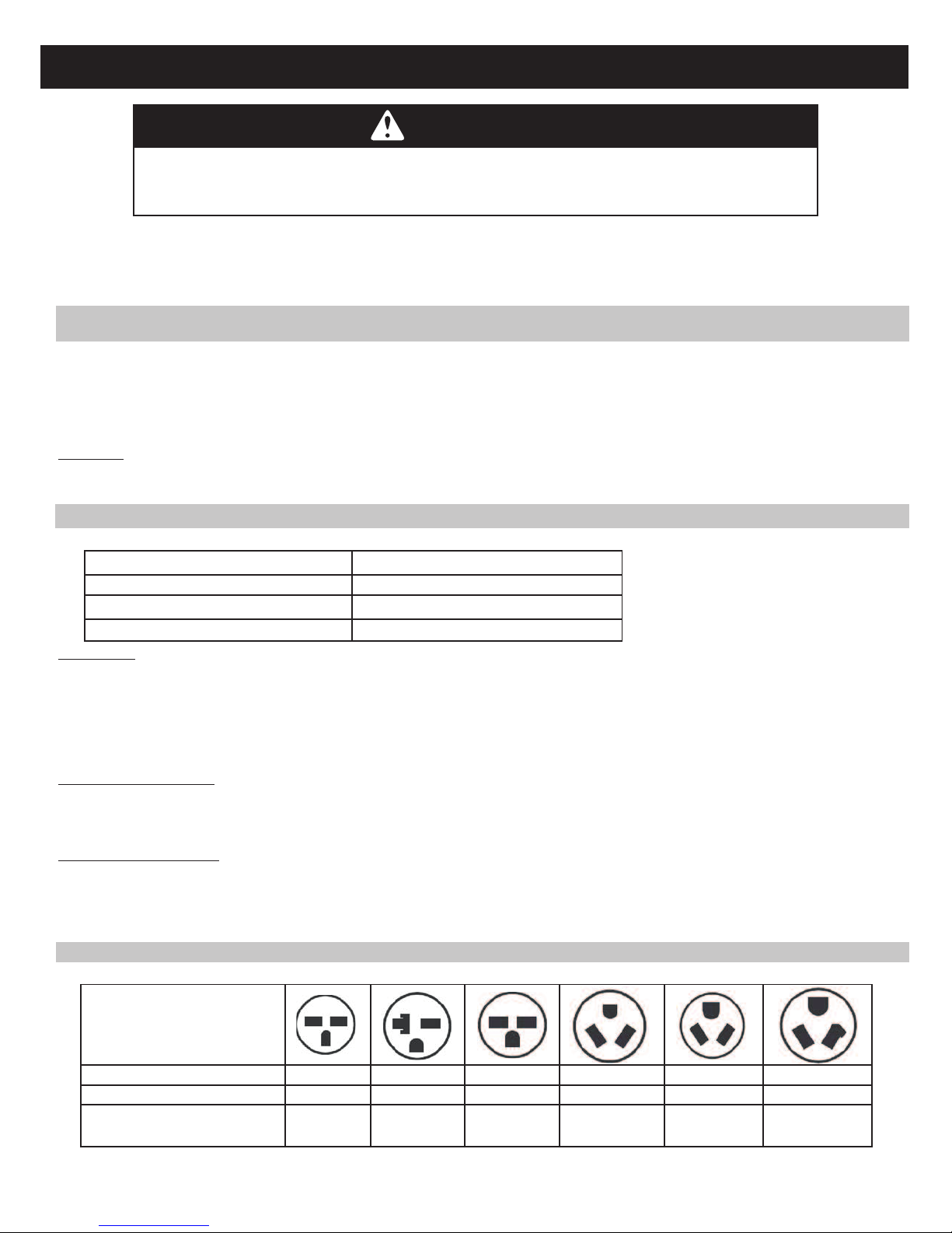
Cord-connected units
The 250V field supplied outlet must match the plug for the standard 208/230V units and be within reach of the power cord.
The standard cord-connected 265V units require an electrical subbase accessory. Refer to Table 2 for the required receptacle
and fuse type.
Power cord protection
The power cord for 230/208V units provides power cord fire protection. Unit power automatically turns off when unsafe
conditions are detected. Power to the unit can be restored by pressing the reset button on the plug head.
Check voltage supply at outlet. For satisfactory results, the voltage range must always be within the ranges found on the data
information plate.
AWG WIRE SIZE†
14
12
10
NAMEPLATE AMPS
7.0 to 12
12.1 to 16
16.1 to 24
Table 2—RECEPTACLES AND FUSE TYPES — 250, 265 VOLTS
R
ECEPTACLE
L
EGEND : HACR - - He ating, Air Condition ing, Refrigerat ion.
* M
ay be used for 15 - amp appl ications
A
MPS 15
15
2
0
20*
30
30
1
5
15
2
0
20
3
0
30
RATED VOLTS 250 250 250 265 265 265
TIME — DELAY TYPE FUSE
(or HACR circuit breaker)
Upon completing the unit installation of 230/208V models, an operational check should be performed using the TEST/RESET
buttons on the plug head.
NOTE: The 265V models do not include this feature, as they require the electrical subbase accessory.
IMPORTANT: For 265V units, if power cord accessory is selected, the cord is only 18” long and must plug into the
electrical 265V subbase receptacle accessory.
Be sure that your outlet matches the plugʼs prong configuration and that the power cord will reach it.
All wiring, including installation of the receptacle, must be in accordance with the NEC and local codes, ordinances and
regulations. National codes require the use of an arc fault or leakage current detection device on all 208/230V power cords.
Be sure to select the correct cord for your installation.
NOTE: Use copper conductors only.
 Loading...