

Gree FP-34BA2/D-K, FP-51BA2/A-K, FP-51BA2/D-K, FP-68BA2/D-K, FP-85BA2/D-K Service Manual
...Page 1
WALL MOUNTED TYPE FAN COIL
UNIT SERVICE MANUAL
(GC201411-I)
Page 2

CONTENTS
PRODUCT ������������������������������������������������������������������������������������������������������ 2
1 MODELS LIST ����������������������������������������������������������������������������������������������������������� 2
2 NOMENCLATURE OF THE UNIT ������������������������������������������������������������������������������ 3
3 FUNCTION ������������������������������������������������������������������������������������������������������������������ 4
4 PRODUCT DATA �������������������������������������������������������������������������������������������������������� 5
CONTROL ����������������������������������������������������������������������������������������������������� 12
1 WIRELESS REMOTE CONTROLLER �������������������������������������������������������������������� 12
2 OPERATION OF WIRELESS REMOTE CONTROL ������������������������������������������������ 13
3 OPERATION OF WIRELESS REMOTE CONTROL ������������������������������������������������ 14
4 OPERATION OF WIRELESS REMOTE CONTROL ������������������������������������������������ 15
5 CHANGING BATTERIES AND NOTICES ���������������������������������������������������������������� 15
6 WIRED CONTROLLER OPERATION (OPTIONAL) ������������������������������������������������ 16
INSTALLATION ��������������������������������������������������������������������������������������������� 31
1 INSTALLATION OF THE UNIT ��������������������������������������������������������������������������������� 31
2 INSTALLATION DIMENSION DIAGRAM ����������������������������������������������������������������� 32
3 INSTALL THE UNIT �������������������������������������������������������������������������������������������������� 33
MAINTENANCE �������������������������������������������������������������������������������������������� 37
1 TROUBLESHOOTING ���������������������������������������������������������������������������������������������� 37
2 MAINTENANCE INSTRUCTIONS ���������������������������������������������������������������������������� 38
3 WIRING DIAGRAMS ������������������������������������������������������������������������������������������������ 39
4 EXPLODED VIEWS AND SPARE PART LISTS ������������������������������������������������������ 42
Page 3

1
Wall Mounted Type
Fan Coil Unit Service Manual
PRODUCT
PRODUCT
Page 4
Wall Mounted Type
Fan Coil Unit Service Manual
2
PRODUCT
PRODUCT
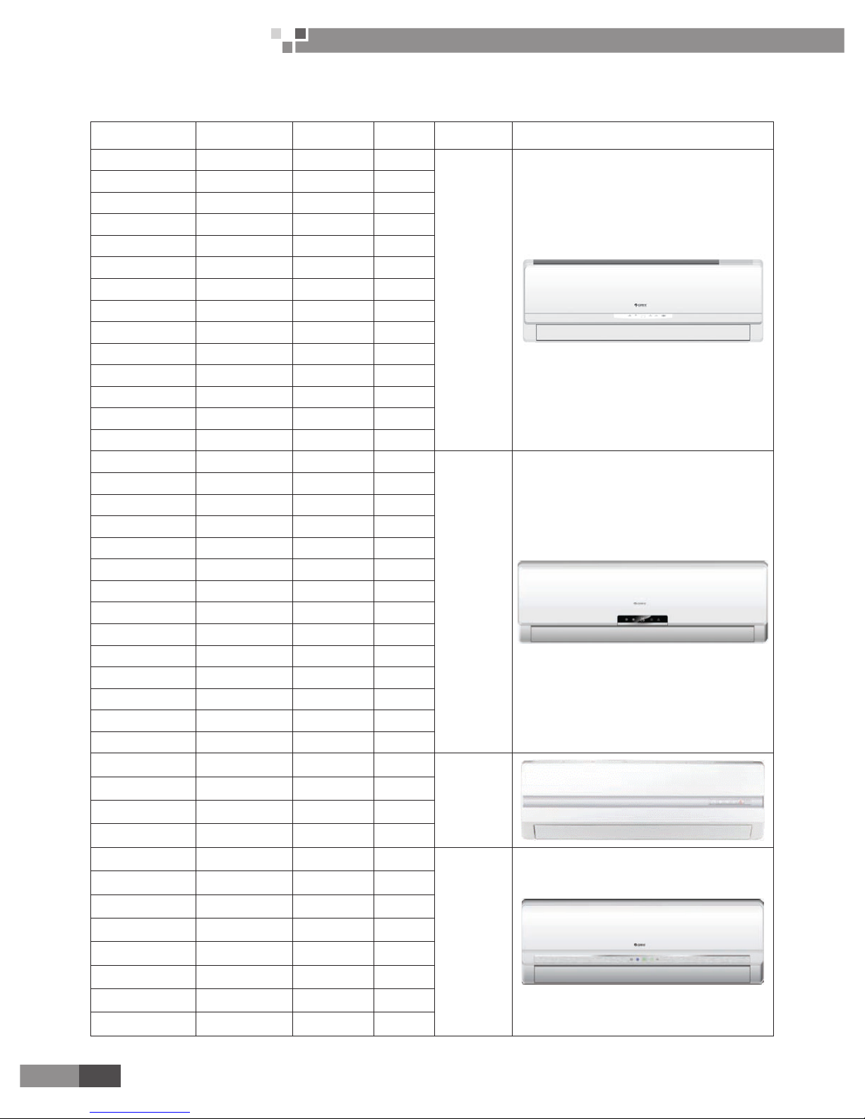
1 MODELS LIST
Model Name
Cooling Capacity
(W)
Product Code
Air Flow
(m3/h)
Power Supply
(V,Ph,Hz)
Remarks
FP-34BA2/A-K 2100 EM55000200 360
220-240V~
50Hz
FP-51BA2/A-K 2700 EM55000210 550
FP-68BA2/A-K 3600 EM55000220 680
FP-85BA2/A-K 4200 EM55000230 850
FP-51BWA2/A-K 1500 EM55000240 450
FP-85BWA2/A-K 2500 EM55000250 650
FP-34BA2/D-K 2000 EM55001810 360
FP-51BA2/D-K 2500 EM55001820 550
FP-68BA2/D-K 3600 EM55001830 680
FP-85BA2/D-K 4200 EM55001840 850
FP-34BA2/B-K 2300 EM55001710 360
FP-51BA2/B-K 2900 EM55001700 550
FP-68BA2/B-K 3800 EM55001690 680
FP-85BA2/B-K 4800 EM55001680 850
FP-34BA3/A-K 2100 EM55001130 360
220-240V~
50Hz
FP-51BA3/A-K 2700 EM55001210 550
FP-68BA3/A-K 3600 EM55001290 680
FP-85BA3/A-K 4200 EM55001360 850
FP-34BA3/B-K 2300 EM55001720 360
FP-51BA3/B-K 2900 EM55001730 550
FP-68BA3/B-K 3800 EM55001750 680
FP-85BA3/B-K 4800 EM55001740 850
FP-51BWA3/A-K 1500 EM55001430 450
FP-85BWA3/A-K 2400 EM55001510 650
FP-34BA3/D-K 2000 EM55002000 360
FP-51BA3/D-K 2500 EM55002010 550
FP-68BA3/D-K 3600 EM55002020 680
FP-85BA3/D-K 4200 EM55002030 850
FP-34BB3/A-K 2100 EM55001180 360
220-240V~
50Hz
FP-51BB3/A-K 2700 EM55001260 550
FP-68BB3/A-K 3600 EM55001340 680
FP-85BB3/A-K 4200 EM55001410 850
FP-34BA4/A-K 2100 EM55001140 360
220-240V~
50Hz
FP-51BA4/A-K 2700 EM55001220 550
FP-68BA4/A-K 3600 EM55001300 680
FP-85BA4/A-K 4200 EM55001370 850
FP-34BA4/D-K 2000 EM55002040 360
FP-51BA4/D-K 2500 EM55002050 550
FP-68BA4/D-K 3600 EM55002060 680
FP-85BA4/D-K 4200 EM55002070 850
Page 5

3
Wall Mounted Type
Fan Coil Unit Service Manual
PRODUCT
FP-34BA5/A-K 2100 EM55000260 360
220-240V~
50Hz
FP-51BA5A-K 2700 EM55000270 550
FP-68BA5/A-K 3600 EM55000280 680
FP-85BA5/A-K 4200 EM55000290 850
FP-51BWA5/A-K 1500 EM55000300 450
FP-85BWA5/A-K 2500 EM55000310 650
FP-34BA5/D-K 2000 EM55002080 360
FP-51BA5/D-K 2500 EM55002090 550
FP-68BA5/D-K 3600 EM55002100 680
FP-85BA5/D-K 4200 EM55002110 850
FP-34BA5/B-K 2300 EM55001670 360
FP-51BA5/B-K 2900 EM55001660 550
FP-68BA5/B-K 3800 EM55001650 680
FP-85BA5/B-K 4800 EM55001640 850
FP-85BA2/A-D 5400 EM55001590 1000
208-230V~
60Hz
FP-34BA2/B-D 2100 EM55000320 360
FP-51BA2/B-D 2700 EM55000330 550
FP-68BA2/B-D 3600 EM55000340 680
FP-85BA2/B-D 4200 EM55000350 850
FP-102BA2/B-D 5400 EM55000360 1000
FP-34BA3/B-D 2100 EM55001760 360
208-230V~
60Hz
FP-51BA3/B-D 2700 EM55001800 550
FP-68BA3/B-D 3600 EM55001770 680
FP-85BA3/B-D 4200 EM55001780 850
FP-102BA3/B-D 5400 EM55001790 1000
FP-34BA5/B-D 2100 EM55001890 360
208-230V~
60Hz
FP-51BA5/B-D 2700 EM55001900 550
FP-68BA5/B-D 3600 EM55001910 680
FP-85BA5/B-D 4200 EM55001920 850
FP-102BA5/B-D 5400 EM55001930 1000
2 NOMENCLATURE OF THE UNIT
FP - □ □ □ /
□ - □
1 2 3 4
4 6
NO. Description Options
1 Fan coil
2 Air ow volume Number×10 m3/h
3 Structure type mounted-B Wall, mounted with water valve-BW
4 Front panel code One letter +one number
5 Design Sequence Arranged by A, B,C…
6 Power code K-220-240V~ 50Hz, D-208-230V~ 60Hz
Page 6
Wall Mounted Type
Fan Coil Unit Service Manual
4
PRODUCT
3 FUNCTION
Function
Fan Coil Unit
Service Manual for Evaluation
For Comfortable
Air Conditioning
Cooling YES
Heating YES
Dehumidify YES
Air Flow YES
Auto Swing YES
Sleep and Auto YES
With Access Control System Optional
Central Control Optional
Wired Controller Optional
Long Distance Control Optional
Timer YES
Energy Saving YES
Anti Cold Air YES
Anti Heat Air YES
Waste Heat Blow YES
Memory YES
Self Diagnosis YES
Alarming YES
Page 7
5
Wall Mounted Type
Fan Coil Unit Service Manual
PRODUCT
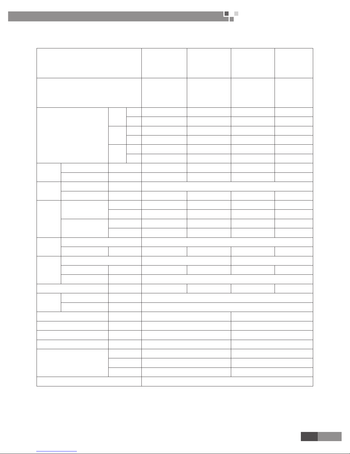
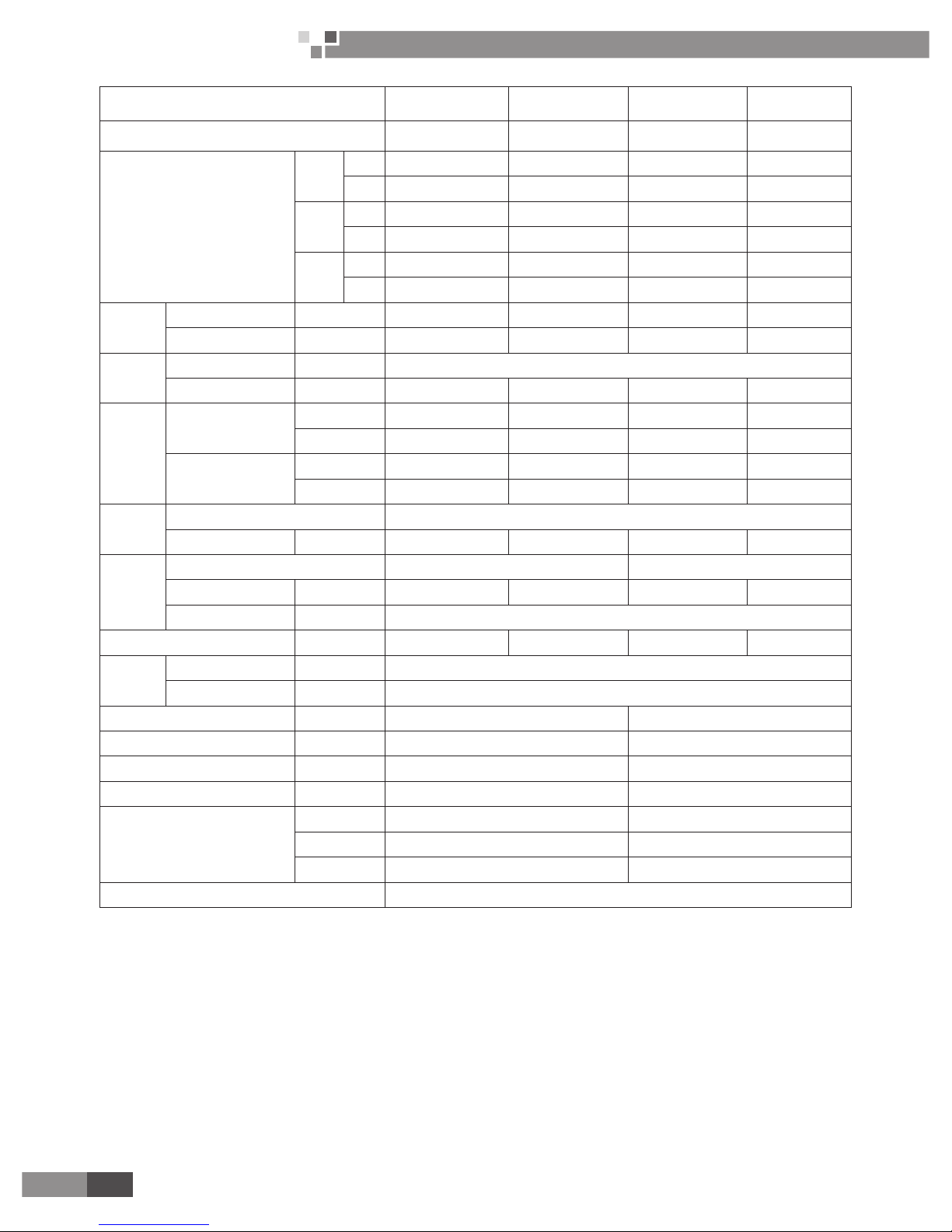
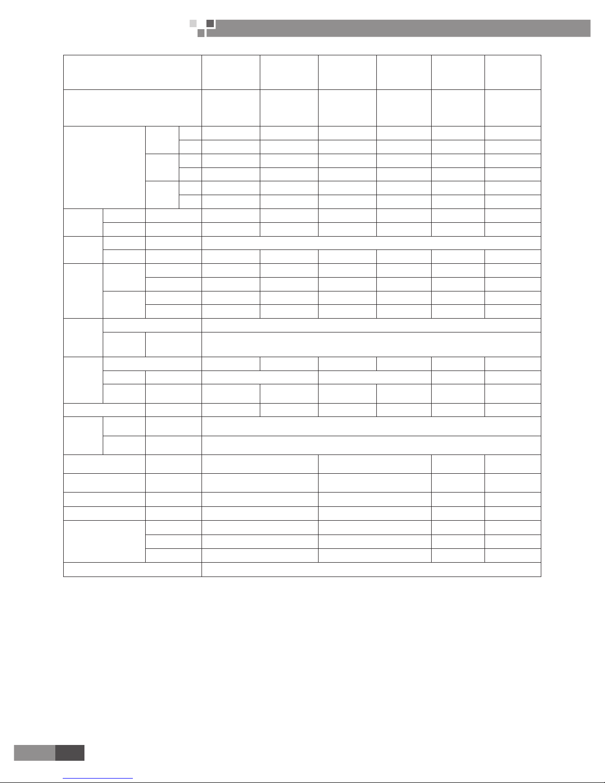
4 PRODUCT DATA
Model
FP-34BA2/A-K
FP-34BA3/A-K
FP-34BA4/A-K
FP-34BA5/A-K
FP-51BA2/A-K
FP-51BA3/A-K
FP-51BA4/A-K
FP-51BA5/A-K
FP-68BA2/A-K
FP-68BA3/A-K
FP-68BA4/A-K
FP-68BA5/A-K
FP-85BA2/A-K
FP-85BA3/A-K
FP-85BA4/A-K
FP-85BA5/A-K
Product Code
EM55000200
EM55001130
EM55001140
EM55000260
EM55000210
EM55001210
EM55001220
EM55000270
EM55000220
EM55001290
EM55001300
EM55000280
EM55000230
EM55001360
EM55001370
EM55000290
Air ow volume
High
m3/h 360 550 680 850
CFM 212 324 400 500
Medium
m3/h 322 413 591 708
CFM 189 242 347 416
Low
m3/h 282 367 532 616
CFM 166 215 312 362
Capacity
Cooling W 2100 2700 3600 4200
Heating W 3150 4050 5400 6300
Power
system
Type V-Ph-Hz 220-240V~ 50Hz
Input W 50 50 60 60
Water
system
Water ow volume
m3/h 0.4 0.45 0.6 0.7
GPM 1.76 1.98 2.64 3.08
Pressure drop
kPa 13 24 44 45
Ft·WG 4.3 7.9 14.5 14.8
Coil
Type Aluminum n-copper tube
Operating pressure MPa ≤1.6MPa ≤1.6MPa ≤1.6MPa ≤1.6MPa
Motor
Type FN20J-PG FN20V-PG
Capacitor uF 1 1 1.5 1.5
Power output W 20
Sound pressure level dB(A) 35 40 43 48
Connection
pipe size
Water inlet &outlet inch 1/2"
Condensing water drain mm 15.6
Outline dimension (W×D×H) mm 845×180×275 940×200×298
Package dimension (W×D×H) mm 915×255×355 1010×285×380
Net weight kg 11 13
Gross weight kg 14 17
Loading quantity
20'GP 365 290
40'GP 765 595
40'HQ 850 671
Standard wireless remote controller YB1FA
Page 8
Wall Mounted Type
Fan Coil Unit Service Manual
6
PRODUCT
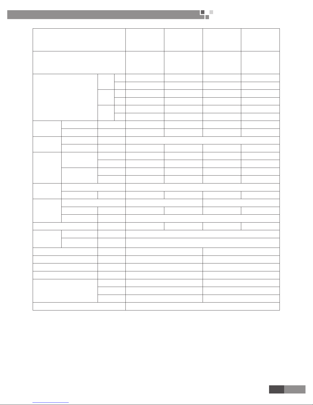
Model FP-34BB3/A-K FP-51BB3A-K FP-68BB3A-K FP-85BB3/A-K
Product Code EM55001180 EM55001260 EM55001340 EM55001410
Air ow volume
High
m3/h 360 550 680 850
CFM 212 324 400 500
Medium
m3/h 322 413 591 708
CFM 189 242 347 416
Low
m3/h 282 367 532 616
CFM 166 215 312 362
Capacity
Cooling W 2100 2700 3600 4200
Heating W 3150 4050 5400 6300
Power
system
Type V-Ph-Hz 220-240V~ 50Hz
Input W 50 50 60 60
Water
system
Water ow volume
m3/h 0.4 0.45 0.6 0.7
GPM 1.76 1.98 2.64 3.08
Pressure drop
kPa 13 24 44 45
Ft·WG 4.3 7.9 14.5 14.8
Coil
Type Aluminum n-copper tube
Operating pressure MPa ≤1.6MPa ≤1.6MPa ≤1.6MPa ≤1.6MPa
Motor
Type FN20J-PG FN20V-PG
Capacitor uF 1 1 1.5 1.5
Power output W 20
Sound pressure level dB(A) 35 40 43 48
Connection
pipe size
Water inlet &outlet inch 1/2"
Condensing water drain mm 15.6
Outline dimension (W×D×H) mm 845×180×275 940×200×298
Package dimension (W×D×H) mm 915×255×355 1010×285×380
Net weight kg 10 12
Gross weight kg 12.5 16
Loading quantity
20'GP 365 290
40'GP 765 595
40'HQ 850 671
Standard wireless remote controller YB1FA
Page 9
7
Wall Mounted Type
Fan Coil Unit Service Manual
PRODUCT
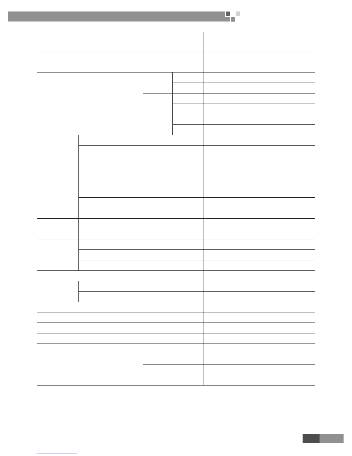
Model
FP-51BWA2/A-K
FP-51BWA3/A-K
FP-51BWA5/A-K
FP-85BWA2/A-K
FP-85BWA3/A-K
FP-85BWA5/A-K
Product Code
EM55000240
EM55001430
EM55000300
EM55000250
EM55001510
EM55000310
Air ow volume
High
m3/h 450 650
CFM 265 382
Medium
m3/h 383 560
CFM 225 329
Low
m3/h 323 490
CFM 190 288
Capacity
Cooling W 1500 2400
Heating W 2250 3600
Power system
Type V-Ph-Hz 220-240V~ 50Hz
Input W 50 60
Water system
Water ow volume
m3/h 0.28 0.38
GPM 1.23 1.67
Pressure drop
kPa 37 60
Ft·WG 12.2 19.7
Coil
Type Aluminum n-copper tube
Operating pressure MPa ≤1.6MPa ≤1.6MPa
Motor
Type FN20J-PG FN20V-PG
Capacitor uF 1 1.5
Power output W 20 20
Sound pressure level dB(A) 42 50
Connection
pipe size
Water inlet &outlet inch 1/2"
Condensing water drain mm 15.6
Outline dimension (W×D×H) mm 845×180×275 940×200×298
Package dimension (W×D×H) mm 915×255×355 1010×285×380
Net weight kg 11 13
Gross weight kg 14 17
Loading quantity
20'GP 365 290
40'GP 765 595
40'HQ 850 671
Standard wireless remote controller YB1FA
Page 10
Wall Mounted Type
Fan Coil Unit Service Manual
8
PRODUCT
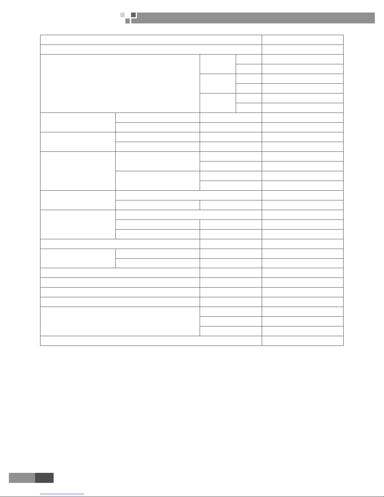
Model FP-85BA2/A-D
Product Code EM55001590
Air ow volume
High
m3/h 1000
CFM 588
Medium
m3/h 840
CFM 493
Low
m3/h 720
CFM 423
Capacity
Cooling W 5400
Heating W 8500
Power system
Type V-Ph-Hz 208-230V~ 60Hz
Input W 70
Water system
Water ow volume
m3/h 0.88
GPM 3.87
Pressure drop
kPa 63
Ft·WG 20.7
Coil
Type Aluminum n-copper tube
Operating pressure MPa ≤1.6MPa
Motor
Type FN20W-PG
Capacitor uF 1.5
Power output W 20
Sound pressure level dB(A) 49
Connection pipe size
Water inlet &outlet inch 1/2"
Condensing water drain mm 15.6
Outline dimension (W×D×H) mm 940×200×298
Package dimension (W×D×H) mm 1010×285×380
Net weight kg 13
Gross weight kg 17
Loading quantity
20'GP 290
40'GP 595
40'HQ 671
Standard wireless remote controller YB1FA
Page 11
9
Wall Mounted Type
Fan Coil Unit Service Manual
PRODUCT
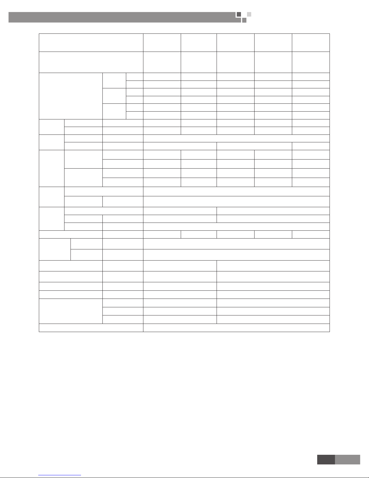
Model
FP-34BA2/B-D
FP-34BA3/B-D
FP-34BA5/B-D
FP-51BA2/B-D
FP-51BA3/B-D
FP-51BA5/B-D
FP-68BA2/B-D
FP-68BA3/B-D
FP-68BA5/B-D
FP-85BA2/B-D
FP-85BA3/B-D
FP-85BA5/B-D
FP-102BA2/B-D
FP-102BA3/B-D
FP-102BA5/B-D
Code
EM55000320
EM55001760
EM55001890
EM55000330
EM55001800
EM55001900
EM55000340
EM55001770
EM55001910
EM55000350
EM55001780
EM55001920
EM55000360
EM55001790
EM55001930
Air ow volume
High
m3/h
360 550 680 850 1000
CFM 212 324 400 500 588
Medium
m3/h 322 413 591 708 840
CFM 189 242 347 416 493
Low
m3/h
282 367 532 616 720
CFM
166 215 312 362 423
Capacity
Cooling W 2100 2700 3600 4200 5400
Heating W 3150 4050 5400 6300 8500
Power
system
Type V-Ph-Hz 208-230V~ 60Hz
Input W 50 60 70
Water
system
Water ow
volume
m3/h
0.4 0.45 0.64 0.78 0.88
GPM 1.76 1.98 2.82 3.43 3.87
Pressure drop
kPa 13 24 44 45 63
Ft·WG 4.3 7.9 14.5 14.8 20.7
Coil
Type Aluminum n-copper tube
Operating
pressure
MPa ≤1.6MPa
Motor
Type FN20X-PG FN20W-PG
Capacitor uF 1 1.5
Power output W 20
Sound pressure level dB(A) 35 40 43 48 49
Connection
pipe size
Water inlet
&outlet
inch 1/2"
Condensing
water drain
mm 15.6
Outline dimension
(W×D×H)
mm 845×180×275 940×200×298
Package dimension
(W×D×H)
mm 915×255×355 1010×285×380
Net weight kg 11 13
Gross weight kg 14 17
Loading quantity
20'GP
365 290
40'GP
765 595
40'HQ 850 671
Standard wireless remote controller YB1FA(X-FAN)
Page 12
Wall Mounted Type
Fan Coil Unit Service Manual
10
PRODUCT
Model
FP-34BA2/B-K
FP-34BA3/B-K
FP-34BA5/B-K
FP-51BA2/B-K
FP-51BA3/B-K
FP-51BA5/B-K
FP-68BA2/B-K
FP-68BA3/B-K
FP-68BA5/B-K
FP-85BA2/B-K
FP-85BA3/B-K
FP-85BA5/B-K
FP-51BWA3/
A-K
FP-85BWA3/
A-K
Code
EM55001710
EM55001720
EM55001670
EM55001700
EM55001730
EM55001660
EM55001690
EM55001750
EM55001650
EM55001680
EM55001740
EM55001640
EM55001430 EM55001510
Air ow volume
High
m3/h 360 550 680 850 450 650
CFM 212 324 400 500 265 383
Medium
m3/h 322 413 591 708 383 560
CFM 189 243 348 417 225 330
Low
m3/h 282 367 532 616 328 490
CFM 166 216 313 363 193 288
Capacity
Cooling W 2300 2900 3800 4800 1500 2400
Heating W 4050 4850 6000 6900 2250 3600
Power
system
Type V-Ph-Hz 220-240V~ 50Hz
Input W 30 30 40 60 50 60
Water
system
Water ow
volume
m3/h 0.43 0.49 0.78 0.9 0.28 0.38
GPM 1.89 2.16 3.43 3.96 1.23 1.67
Pressure
drop
kPa 19 23 49 55 37 60
Ft·WG
6.4 7.7 16.4 18.4 12.2 19.7
Coil
Type Aluminum n-copper tube
Operating
pressure
MPa ≤1.6MPa
Motor
Type FN6B FN9A FN13G FN23A FN20J-PG FN20V-PG
Capacitor uF 1 1.5 1 1.5
Power
output
W 6 9 13 22 20 20
Sound pressure level dB(A) 35 40 43 48 42 50
Connection
pipe size
Water inlet
&outlet
inch 1/2"
Condensing
water drain
mm 15.6
Outline dimension
(W×D×H)
mm 845×180×275 940×200×298 845×180×275 940×200×298
Package dimension
(W×D×H)
mm 915×255×355 1010×285×380 915×255×355 1010×285×380
Net weight kg 8.8 10.8 11 13
Gross weight kg
11.8 14.8 14 17
Loading quantity
20'GP 365 290 365 290
40'GP 765 595 765 595
40'HQ 850 671 850 671
Standard wireless remote controller YB1FA(X-FAN)
Note:
(1) The water working temperature is from 7ºC(44.6ºF) to 60ºC(140ºF).
(2) The temperature exchange efficiency and enthalpy exchange efficiency are tested under these
testing conditions as below:
1) Cooling efciency: air 27ºC (80.6ºF) DB, 19.5ºC (67.1ºF) WB, water temperature in 7ºC (44.6ºF) water
out 12ºC(53.6ºF).
2) Heating efciency: air 21ºC (69.8ºF) DB, Water temperature: 60ºC(140 ºF).
(3) The operating water pressure of the models above is no more than 1.6MPa.
Page 13
11
Wall Mounted Type
Fan Coil Unit Service Manual
PRODUCT
Model
FP-34BA2/D-K
FP-34BA3/D-K
FP-34BA4/D-K
FP-34BA5/D-K
FP-51BA2/D-K
FP-51BA3/D-K
FP-51BA4/D-K
FP-51BA5/D-K
FP-68BA2/D-K
FP-68BA3/D-K
FP-68BA4/D-K
FP-68BA5/D-K
FP-85BA2/D-K
FP-85BA3/D-K
FP-85BA4/D-K
FP-85BA5/D-K
Product Code
EM55001810
EM55002000
EM55002040
EM55002080
EM55001820
EM55002010
EM55002050
EM55002090
EM55001830
EM55002020
EM55002060
EM55002100
EM55001840
EM55002030
EM55002070
EM55002110
Air ow volume
High
m3/h 360 550 680 850
CFM 212 324 400 500
Medium
m3/h 322 413 591 708
CFM 189 242 347 416
Low
m3/h 282 367 532 616
CFM 166 215 312 362
Capacity
Cooling W 2000 2500 3600 4200
Heating W 2700 3200 4600 5400
Power system
Type V-Ph-Hz 220-240V~ 50Hz
Input W 50 50 60 66
Water system
Water ow volume
m3/h 0.4 0.45 0.6 0.7
GPM 1.76 1.98 2.65 3.09
Pressure drop
kPa 20 36 53 70
Ft·WG 7 12 17 23
Coil
Type Aluminum n-copper tube
Operating pressure MPa ≤1.6MPa ≤1.6MPa ≤1.6MPa ≤1.6MPa
Motor
Type FN20J-PG FN20V-PG
Capacitor uF 1 1 1.5 1.5
Power output W 20
Sound pressure level dB(A) 35 40 43 48
Connection
pipe size
Water inlet &outlet inch 1/2"
Condensing
water drain
mm 15.6
Outline dimension (W×D×H) mm 845×180×275 940×200×298
Package dimension (W×D×H) mm 915×255×355 1010×285×380
Net weight kg 10 12
Gross weight kg 12.5 16
Loading quantity
20'GP 365 290
40'GP 765 595
40'HQ 850 671
Standard wireless remote controller YB1FA(XFAN)
Note:
(1) The water working temperature is from 7ºC(44.6ºF) to 60ºC(140ºF).
(2) The temperature exchange efficiency and enthalpy exchange efficiency are tested under these
testing conditions as below:
1) Cooling efciency: air 27ºC (80.6ºF) DB, 19ºC (66.2ºF) WB, water temperature in 7ºC (44.6ºF) water out
12ºC(53.6ºF).
2) Heating efciency: air 20ºC (68ºF) DB, water temperature in 50ºC (122ºF) , water out 40ºC (104ºF).
(3) The operating water pressure of the models above is no more than 1.6MPa.
Page 14

Wall Mounted Type
Fan Coil Unit Service Manual
12
CONTROL
CONTROL
Page 15

13
Wall Mounted Type
Fan Coil Unit Service Manual
CONTROL
13
CONTROL
CONTROL
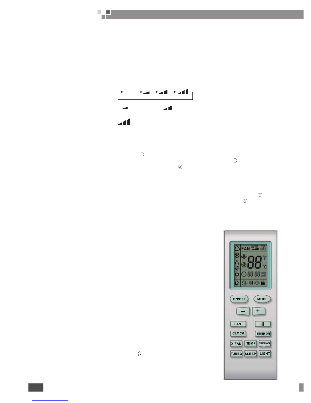
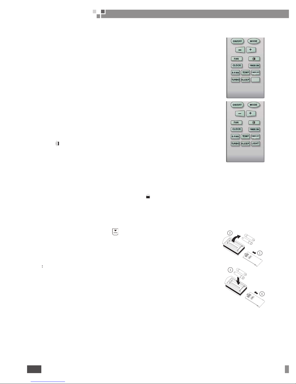
1 WIRELESS REMOTE CONTROLLER
Names and functions of wireless remote control
Note: Be sure that there are no obstructions between receiver and remote controller; Don't drop or throw the
remote control; Don't let any liquid in the remote control and put the remote control directly under the sunlight or
any place where it is very hot.
1�1 ON/OFF
ON/OFF button
Press
ON/OFF
button to turn on/off the unit. When the unit is turned off, the Timer, Sleep function will not be
retained in memory, but the time will be retained and is still displaying.
1�2 MODE
MODE button
①
Press this button, Auto, Cool, Dry, Fan Heat mode can be selected circularly.
②
Under Cool mode, the initial value is 24°C(75°F) . Under Heat mode, the initial values 24°C(75°F).
Auto mode is not available in this mode.
AUTO
COOL
DRY
FA N
HEAT
Page 16
Wall Mounted Type
Fan Coil Unit Service Manual
14
CONTROL
1�3 SLEEP
SLEEP
button
Press this button to select Sleep On/Sleep Off. If power is on, Sleep Off is default. If the unit is turned off, the
Sleep function setting will be not retained in memory. If Sleep function is on, the mark of Sleep will display. In
this mode, the time of timer can be adjusted. Under Fan and Auto modes, this function is not available.
1�4 FAN
FAN
button
Press this button, Auto, Low, Medium, High-speed can be circularly selected. After powered on, Auto fan
speed is default. Under Dehumidify mode, Low fan speed is default.
MediumLow
High
AUTO
Note: Under the Dry mode, the fan speed isn't adjustable, low fan speed is default.
1�5 CLOCK
CLOCK button
Press Clock button to set the time of clock. When blinks and displays, you can set the time by pressing + or - button.
If no button is pressed within 10 seconds the remote will revert back to the normal display. Press again to accept the
setting. If it is set the rst time, 12:00 is the initial value. Note: If mark
displays on the LCD, it means it is the time of
clock, if not, it is the time of timer.
1�6 LIGHT
LIGHT button
Press this button to select LIGHT On/Off in the displayer. When the LIGHT On is set, the mark will be
displayed and the indicator light in the displayer will be on. When the LIGHT Off is set, the mark will disappear
and the indicator light will be off.
2 OPERATION OF WIRELESS REMOTE CONTROL
Note: This is a general remote control, it could be used for multiple types (functions) of air conditioners. For
some models without the functions specified here, we preserve the right to not to
inform exclusively.
2�1 X-FAN
X-FAN
button
①
Press this button to turn on/off the X-FAN function.
②
The function is not available for this function.
2�2 - button
Presetting temperature can be decrease the temperature by 1 degree Celsius
once. press and hold for more than two seconds so that we can change the
temperature continuously. The minimum and maximum setting range of the
temperature is 16 to 30 degree Celsius.
2�3 + button
Press this button increase the temperature by 1 degree Celsius once. Press and
hold for more than two seconds so that we can change the temperature continuously.
The minimum and maximum setting range of the temperature is 16 to 30 degree.
2�4 TEMP�
TEMP�
button
Press this button to select the display of either indoor setting temperature or
indoor ambient temperature. When the indoor unit powered on firstly, setting
temperature display is default. Change status to to display the ambient temperature.
If received control signal in 5 seconds, the display temp.will revert back to setting
temperature. When unit is off, indoor setting temperature display is default. Note:
This function is only available for certain models.
Page 17
15
Wall Mounted Type
Fan Coil Unit Service Manual
CONTROL
15
CONTROL
2�5 TURBO
TURBO
button
In Cool or Heat mode, press this button to turn on/off the Turbo function.
Note: This function is not available for this model.
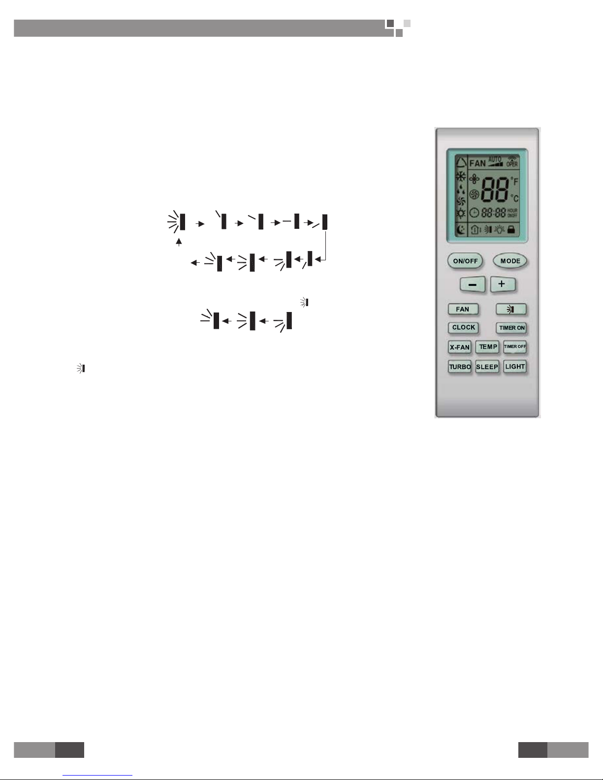
3 OPERATION OF WIRELESS REMOTE CONTROL
Note:
This is a general remote control, it could be used for multiple types
(functions) of air conditioners. For some models without the functions specied here,
we preserve the right to not to inform exclusively.
3�1 SWING UP AND DOWN BUTTON
Press this button to adjust swing angle, which circularly changes as below:
OFF
This is a general use remote control. If remote control shows the following three
kinds of status that the swing status of main unit will be:
When the guide louver start to swing up and down, if turn off the Swing, the air
guide louver will stop at current position.
which indicates the guide louver swings up and down between the ve positions.
3�2 TIMER ON BUTTON
Press the TIMER ON button to set the timed On. Press +/- once to increase or
decrease the minute by 1 minute. If pressed and held for 2 seconds, the minute will
increase or decrease constantly by 1 minute. If held constantly for more than 5 seconds, the minute will begin
to change in every 10 minutes. Press TIMER ON again to accept the setting and ON will show besides the time
of clock meaning the setting succeeds. Press the TIMER ON again to cancel the setting.
3�3 TIMER OFF BUTTON
Press the TIMER OFF button to set the timed Off. The procedures are similar as above.
Page 18
Wall Mounted Type
Fan Coil Unit Service Manual
16
CONTROL
4 OPERATION OF WIRELESS REMOTE CONTROL
4�1 Guide for operation – General operation
①
Press
SLEEP
button to set the sleep state.
②
Press
TIME ON
and
TIME OFF
button to scheduled the unit
ON/OFF
③
Press
LIGHT
button to control on and off the indicator board.(This function maybe not
available for some units).
4�2
Guide for operation-Optional operation
①
After powered on, press
ON/OFF
button, the unit will start to run. (
Note
: When it is
powered off , the guide louver of main unit will close automatically.)
②
Press
MODE
button, select desired running mode, or press
COOL
or
HEAT
mode to
enter the corresponding operation directly.
③
Press + or-button to set the desired temperature.
④
Press
FAN
button to set fan speed from
AUTO, FAN ,LOW MID
and
HIGH
.
⑤
Press button to select
SWING
mode.
4�3 Operation of wireless remote control
①
Press +and - buttons simultaneously to lock or unlock the wireless remote control. If it is locked, the
mark will display; when pressing any button, the mark will blink for three times but the air conditioner has no
despondence. If unlocked, the mark will disappear.
②
Switch between Fahrenheit and Centigrade.When unit is under Off state, press
MODE
and – button
simultaneously to switch between °C and °F.
5 CHANGING BATTERIES AND NOTICES
①
Slightly to press the place with , along the arrowhead direction to push the
back cover of wireless remote control. (As show in gure)
②
Take out the old batteries. (As show in gure)
③
Insert two new AAA1.5V dry batteries, and pay attention to the polarity. (As show
in gure).
④
Attach the back cover of wireless remote control. (As show in gure)
NOTE
:
●When changing the batteries, do not use the old or different batteries, otherwise, it
can cause the malfunction of the wireless remote control.
●If the wireless remote control will not be used for a long time, please take them out,
and don't let the leakage liquid damage the wireless remote control.
●The operation should be in its receiving range.
●It should be placed at where is 1m away from the TV set or stereo sound sets.
●If the wireless remote control can not operate normally, please take them out, after
30s later and reinsert, if they cannot normally run, please change them.
●leakage liquid damage the wireless remote control.
Sketch map for
changing batteries
Page 19

17
Wall Mounted Type
Fan Coil Unit Service Manual
CONTROL
17
CONTROL
6 WIRED CONTROLLER OPERATION (OPTIONAL)
1 LCD Display
1.1 Symbols on the LCD
Fig.1 Appearance of the Wired Controller
1.2 Introduction to the Symbols on the LCD
Fig.2 Symbols on the LCD
Table 1 Introduction to the Symbols on the LCD
No. Symbol Function Description
1 It indicates the swing function.
2 It indicates the function of air exchange. (It is unavailable for this wired controller.)
3 It indicates the sleeping status.
4 It indicates each running mode of the indoor unit (AUTO mode). (It is unavailable for this wired controller. )
5 It indicates the “Cool” mode.
6 It indicates the “Dry” mode.
7 It indicates the “Fan” mode.
8 It indicates the “Heat” mode.
9 It indicates the defrosting mode. (It is unavailable for this wired controller.)
10 It indicates the gate control status.
11 It indicates the locking status.
Page 20
Wall Mounted Type
Fan Coil Unit Service Manual
18
CONTROL
12
It indicates the shield status. (It appears when all functions, or the function “On/Off”, “Temp”, “Mode”, or “
Save” is shielded through the Long-distance monitoring System.)
13 It indicates the current fan speed.
14
It indicates the memory function is activated, that is, the unit will back to the previous set status after
powered on again.
15 It indicates the turbo status.
16 It ashes animatedly when the unit is started and the ambient temperature is displayed.
17 It indicates the ambient temperature/set temperature.
18 It indicates the energy saving status.
19 It indicates that the auxiliary electric heater can be activated.
20 It indicates the blow function is activated.
21 It indicates the timer status.
22 It indicates the quiet operation status. (including two statuses, “Quiet” and “Auto Quiet”. )
Note: Symbols “MASTER” and “CO2” will not displayed on the LCD of the wired controlled XK26.
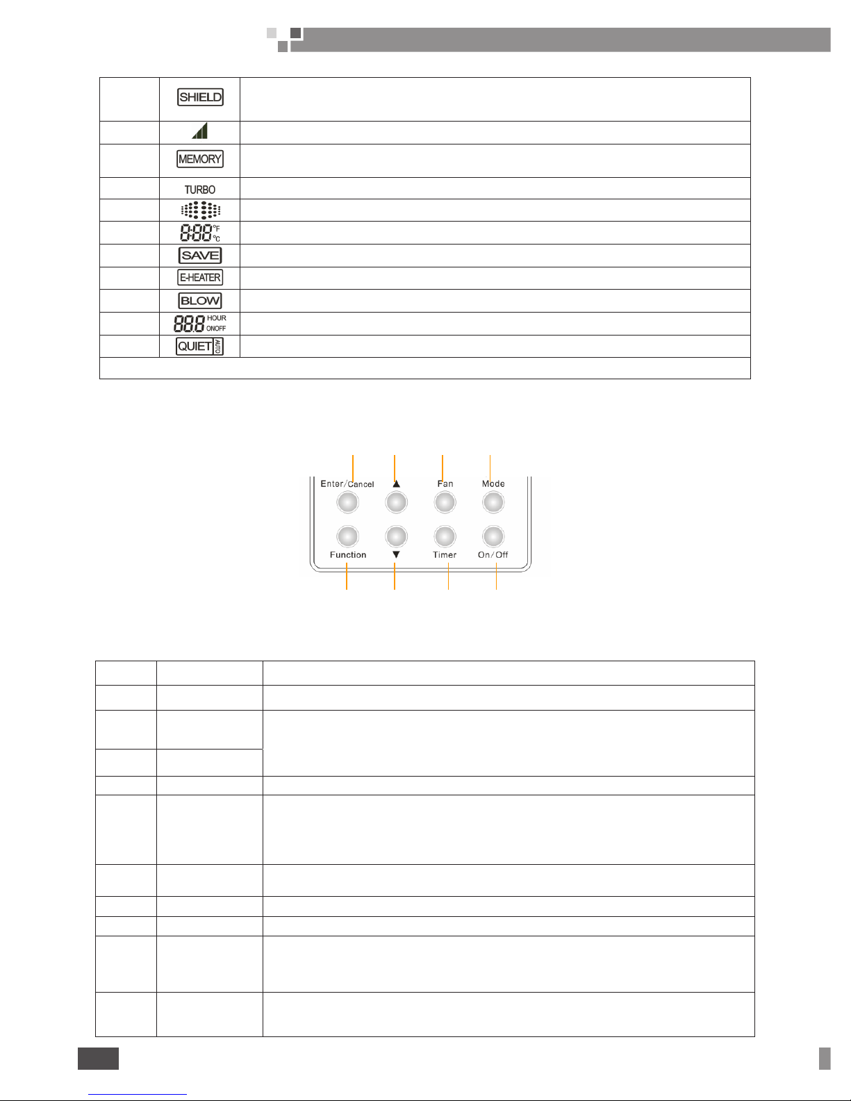
2 Press Keys
2.1 Name of Press Keys
1
5 6 7 8
2 3
2.2 Introduction to the Functions of the Press Keys
Table 2 Introduction to the Functions of the Press Keys
No. Press Bottoms Function Description
1 Enter/Cancel It is used to select the desired function or cancel the selected function.
2 ▲
(1) It is used to adjust the running temperature of the indoor unit among16~30℃.
(2) It is used to adjust the temperature under the energy saving condition among16~30℃.
(3) It is used to adjust the timer among 0.5~24 hours.
(4) It is used to switch between the modes of “Quiet” and “Auto Quiet ”.
6 ▼
3 Fan There are four fan speed options, High, Medium, Low and Auto.
4 Mode
(1) It is used to set the mode of “Cool”,“Dry”, “Fan”, and “Heat”.
(2) When the “Save” function is being set, it is used to switch
between the mode options of “Heat” and “Cool”.
(3) When the “ Timer ” is being set, it is used to switch between the options of “Unit On” and “Unit Off”.
5 Function It is used to switch the functions of “Swing”, “Sleep”, “Turbo”, “Save”, “E-Heater”, “Blow”, “Quiet”, etc.
7 Timer It is used to set the timer.
8 On/Off It is used to start/stop the indoor unit.
4 +2
Mode +▲
(MEMORY)
Under the “Off” status of the unit, press “Mode” and “▲” simultaneously for ve seconds to activate
or deactivate the “MEMORY” function. (once this function is activated, the unit with power failure
will resume the previous set status after powered on again; otherwise it will go to the“Off” status.)
2 +6
▲+▼
(LOCK)
Press “▲” and “▼” simultaneously for ve seconds to go to the lock status, in which case the press
on any other key will get no response. And another press on “▲” and “▼” for ve seconds will quit
this status.
Page 21
19
Wall Mounted Type
Fan Coil Unit Service Manual
CONTROL
19
CONTROL
5+ 7
Function +Timer
(Ambient
Temperature Sensor;
Anti Cold/Hot Air)
Under the “Off ” status of the unit, press “ Function ” and “ Timer ” simultaneously for ve seconds to call
out the debugging menu, after that press “ Mode ” to select the desired submenu and press “▲”/“▼”
to set the parameter, nally press “ Enter/Cancel ” to save the setting and quit the setting status.
4 +6 Mode +▼
Under the “Off ” status of the unit, press “ Mode ” and “▼”simultaneously for ve seconds to switch
the Celsius scale and Fahrenheit scale.
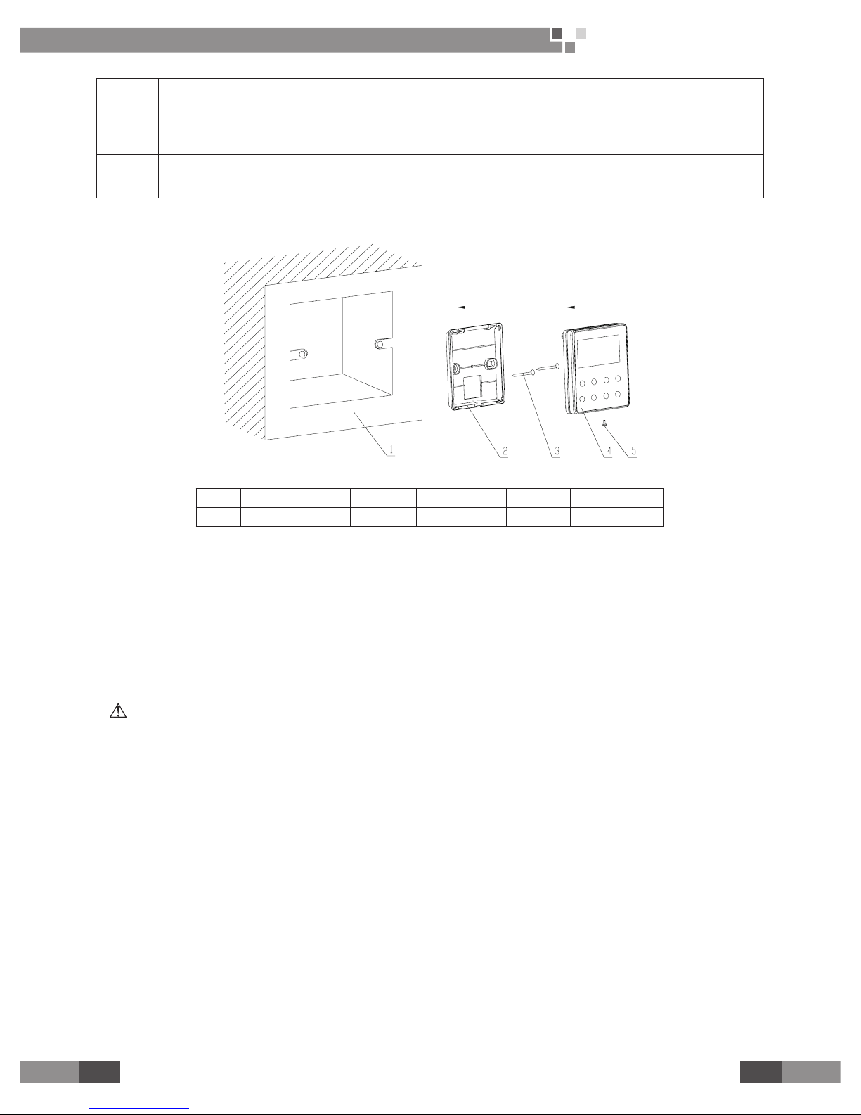
3 Installation Instructions
Fig.4 Installation of the Wired Controller
No. 1 2 3 4 5
Name Installation Box Base Plate Screw M4X25 Front Panel Screw ST2.2X6.5
Fig.4 presents simply how to install the wired controller and please pay special attention to the following
instructions.
(1) Please cut off the power supply for all buried power cords in the installation hole and the whole
installation must be done without any live part.
(2) Pull out the four-core twisted pairs in the installation hole and let it go through the rectangular hole on the
base plate of the wired controller.
(3) Fix the base plate on the wall with screws M4X25.
(4) Let the four-core twisted pairs go through the slot of the wired control and then x the front panel and
base plate together.
(5) Fasten the front panel and base plate with screws ST2.2X6.5.
NOTE
Pay special attention to the electric wiring to prevent that the air conditioner goes out of control owing to the
electromagnetic interference.
①
The signal line and communication line should be separated with the power cord and the connecting wires
between indoor and outdoor units should be with a minimal distance of 20cm, otherwise the communication
would go wrong.
②
If the air conditioner is installed where it would be affected by electromagnetic interference, the signal line
and the communication line must be the shielded twisted pairs.
Page 22

Wall Mounted Type
Fan Coil Unit Service Manual
20
CONTROL
4 Operation Instructions
4.1 On/Off
●Under the “
Off
” status of the unit, press “
On/Off
” to start the unit.
●Under the “On” status of the unit, press “
On/Off
” to stop the unit.
●Fig. 5 is the “
Off
” status when the unit is powered on. Fig.6 show the “On” status when the unit is powered
on.
Fig.5 “
Off
” Status Fig.6 “On” Status
4.2 Mode
Under the “On” status, each press on “
Mode
” can change the modes circularly as the following order.
Cool Dry
Fan
Heat
4�3 Temperature Setting
Under the “On” status, press “▲” and “▼” to increase or decrease the set temperature. A long-time press
will make the temperature go up or down by 1°C/°F per 0.3 seconds.
Temperature Range:16℃~30℃.
Fig. 8 Temperature Setting
Page 23

21
Wall Mounted Type
Fan Coil Unit Service Manual
CONTROL
21
CONTROL
4�5 Swing
How to activate the “
Swing
” function: under the “On” status of the unit, press the “
Function
” key to go to
the setting status with the symbol“ ”ashing, and then press “
Enter/Cancel
” to make a conrmation and the
symbol“ ”will stop ashing.
How to deactivate the “
Swing
” function: under the “On” status of the unit, press the “
Function
” key to go to
the setting status with the symbol“ ”ashing, and then press “
Enter/Cancel
” to deactivate this function and
the symbol will disappear.
See Fig. 10 for how to activate the “
Swing
” function.
When the “Swing”
functions is not activated
Press “Function” to go
to the setting status
Press “
Enter/cancel
”
to activate the “
Swing
”
function
See Fig.11 for how to deactivate the “
Swing
” function.
When the “Swing” is
activated
Press “Function” to go
to the setting status
Press “Enter/cancel” to
deactivate the “Swing”
function
NOTE:
If the setting of the swing function is “
Off
”, the swing angle may change after the unit is powered
on again.
4�6 Timer
Under the “ On” or “
Off
” status, press the “
Timer
” key to set the time when to automatically start or stop the
unit.
How to set timer for unit “On”: Under the “
Off
” state of the unit, press the “
Timer
” key with the symbol “
”in the timer zone ashing, and then press “▲” or “▼” to set when to start the unit, after that, press the “
Timer
”
key again to nish this setting. Before pressing “
Timer
” key to nish the setting for unit “On”, it is also available
to go to set when to stop the unit by pressing the “
Mode
” key with the symbol “ ” ashing, and then press “▲”
or “▼” to adjust the time, after that, press the “
Timer
” to nish this setting. Finally, the time displayed is for the
unit “
On
” while time for unit “
Off
” will not be displayed.
How to set timer for unit “
Off
”: When the unit is “On”, press the “
Timer
” key with the symbol
“ ” ashing, and then press “▲” or “▼” to set the time when to stop the unit, after that, press the “
Timer
” key
again to nish this setting. Before pressing the “
Timer
” key to nish the setting for unit “
Off
”, it is also available
to go to set when to start the unit by pressing the “
Mode
” key with the symbol “ ”ashing, and then press “▲”
or “▼” to adjust the timer, after that, press the “
Timer
” key again to nish the setting. Finally, the time displayed
is for the unit “
Off
” while time for unit “On” will not be displayed.
How to cancel the timer:When the timer is set, press “
Timer
” to cancel it and then no time will be displayed
on the LCD.
Page 24

Wall Mounted Type
Fan Coil Unit Service Manual
22
CONTROL
See Fig.12 for how to set the timer under the “On” status of the unit.
When the timer is not set
Press “Timer” to go to
the setting status
Press “▲” or “▼” to adjust
the time for unit “On”
Press “Timer” to nish
this setting
Press “▲” or “▼” to
adjust the time
Press “Mode” to switch
to setting status for unit
“ON”
Fig.12 How to Set the“
Timer
”
See Fig.13 for how to cancel the timer under the “On” status of the unit.
The timer is set when the unit
is turned on
Press “Timer” to cancel the
setting
Fig. 13 How to Cancel the “
Timer
”
Timer Range: 0.5~24 hours, Each press on “▲”or “▼” will increase or decrease the timer by 0.5 hour. And
the long-time press will increase or decrease the timer by 0.5 hour per 0.3 second.
NOTE
①
When the unit is “On”, if the time for unit “On” and unit “Off” have been set, then only the time for unit “
Off ” will be displayed on the wired controller. When the unit is “
Off
”, if the time for unit “On” and unit “
Off
” have
been set, then only the timer for unit “On” will be displayed on the wired controller.
②
When the unit is “
Off
”, the time for unit “On” starts as soon as the time for unit “
Off
”ends. When the unit is “
On
”, the time for unit “
Off
” starts as soon as the time for unit “On” ends.
4�7 Sleep
(1) Sleep Function
1) Under the “
Cool
” and “
Dry
” Mode, when the unit has run for one hour, the set temperature will go up by
1℃, and then another 1°C in another hour, then the temperature will not change any more.
2) Under the “
Heat
” mode, when the unit has run for one hour, the set temperature will go down by 1°C,
and then another 1°C in another hour, and then the temperature will not change any more.
Page 25

23
Wall Mounted Type
Fan Coil Unit Service Manual
23
(2) How to activate the “
Sleep
” function:When the unit is “On” and the “
Sleep
” function is deactivated, press
the “
Function
” key to go to the setting state of the “
Sleep
” function with the symbol“ ”ashing, after that,
press the “
Enter/Cancel
” key to make a conformation and then the symbol “ ” will stop ashing.
(3) How to deactivate the “
Sleep
” function:When the unit is “On” and the “
Sleep
” function is activated, press “
Function
” to go to the setting state of the sleep function with the symbol“ ”ashing, after that, and then press “
Enter/Cancel
” to make a conrmation and the symbol “ ” will disappear.
See Fig.14 for how to activate the “
Sleep
” function.
When the “Sleep” function
is not activated
Press “Function” to go to
the setting status
Press “Enter/cancel” to
activate the “Sleep” function
Fig.14 How to Activate the “
Sleep
” Function
See Fig.15 for how to deactivate the“
Sleep
”function.
When the “Sleep” function
is activated
Press “Function” to go to
the setting status
Press “Enter/cancel” to
deactivate the “Sleep”
function
Fig.15 How to Deactivate the “
Sleep
” Function
NOTE
①
The default setting for the “
Sleep
” function is “
Off
” when the unit is powered on again after power failure.
②
This function is unavailable under the “Fan” mode.
4�8 Turbo
“
Turbo
” function: It is a function to make the temperature of the conditioned air approach the set value
rapidly through high-speed running of the fan under either “
Cool
” or “
Heat
” mode.
How to active the “
Turbo
” function: under the “
Cool
” or “
Heat
” mode, when the “
Turbo
” function is “
Off
”,
press the “
Function
” key to go to the setting status of the “
Turbo
” function with the symbol“ ” ashing, after
that , press the “
Enter/Cancel
” key to make a conrmation and then the symbol stops ashing.
How to deactivate the “
Turbo
” function:When the unit “On” and the “
Turbo
” function is activated, press the
“
Function
” key to go to the setting state of the “
Turbo
” function with the symbol“ ”ashing, after that, press
the “
Enter/Cancel
” key to make a conrmation and then the symbol“ ”disappear .
Page 26

Wall Mounted Type
Fan Coil Unit Service Manual
24
See Fig.16 for how to activate the “
Turbo
” function.
TUR
B
O
M
E
MOR
Y
S
A
V
E
B
L
O
W
T
U
R
B
O
M
E
M
O
R
Y
S
A
V
E
B
L
O
W
M
E
M
O
R
Y
S
A
V
E
BLO
W
When the “Turbo”
function is not activated
Press “Function” to go
to the setting status
Press “Enter/cancel”
to active the “Turbo”
function
See Fig.17 for how to deactivate the“
Turbo
” function.
TUR
B
O
M
E
M
O
R
Y
S
A
V
E
B
L
O
W
M
E
M
O
R
Y
S
A
V
E
B
L
O
W
TUR
B
O
M
E
MOR
Y
S
A
V
E
B
L
O
W
When the “Turbo”
function is activated
Press “Function” to go
to the setting status
Press “Enter/cancel” to
deactivate the “Turbo”
function
Fig.17 How to Deactivate the “
Turbo
” Function
NOTE:
①
The “
Turbo
” function is deactivated when the unit is powered on after power failure.
②
Under the “
Dry
” and “
Fan
” modes, the “
Turbo
” function is unavailable and the symbol “ ”will not
appear.
③
The “
Turbo
” function will be deactivated automatically when the “
Quiet
” function is activated.
④
The “
Turbo
” function will be deactivated automatically when the “
Fan
” speed is adjusted.
4�9 Save
(1) “
Save
” Function
1) This function is intended to save energy through limiting the temperature range under “
Cool
”, “
Dry
” or
“
Heat
” mode.
2) The set temperature range for energy saving under the “
Cool
” or “
Dry
” mode is from the set point to
30°C .
3) The set temperature range for energy saving under the “
Heat
” mode is from 16°C to the set point.
(2) How to set the “
Save
” function under the “
Cool
” mode.
1) When the unit is “On”, press “
Function
” to go to the setting state of the “
Save
” function with the symbol“
” ashing.
2) Press the “▲” or“▼” key to adjust the set temperature.
3) Press the “
Enter/Cancel
” key to activate the “
Save
” function.
(3) How to set the “
Save
” function under the “
Heat
” mode.
1) When the unit is “On”, press “
Function
” to go the setting state of the “
Save
” function with the symbol“
” ashing.
2) Press “
Mode
” to switch to the setting status for heating.
3) Press “▲”or “▼” to adjust the set temperature.
4) Press “
Enter/Cancel
” to activate the save function.
(4) How to deactivate the “
Save
” function:When the “
Save
” function is activated, press the “
Function
” key to
go to the setting state of this function with the symbol“ ”ashing, after that, press the“
Enter/Cancel
” key to
cancel the “
Save
” function and the symbol will disappear.
Page 27

25
Wall Mounted Type
Fan Coil Unit Service Manual
25
See Fig.18 for how to activate the “
Save
” function.
When the “Save”
function is not activated
Press “Function” to go
to the setting status
Press “▲” or “▼” to
adjust the temperature
for cooling
Press “Enter/cancel”
to activate the “Save”
function
Press “▲” or “▼” to
adjust the temperature for
heating
Press “Mode” to switch
to the setting status for
heating
Fig. 18 How to Activate the “
Saving
” Function
See Fig. 19 how to deactivate the “
Save
” function.
When the “Save”
function is activated
Press “Function” to go
to the setting status
Press “Enter/cancel’ to
deactivate the “Save”
function
Fig.19 How to Deactivate the “
Save
” Function
NOTE
①
The “
Sleep
” function will be deactivated when the “
Save
” function is activated.
②
The “
Save
” function will be memorized when the unit is powered on again after power failure.
③
The initial lower temperature limit under the “
Save
” cooling mode is 16°C and the initial upper temperature
limit is “ 30°C” under the “
Save
” heating mode.
④
When the “
Save
” function is activated, if the set temperature under each mode is higher than the
corresponding temperature limit for energy saving, then the set temperature will forcibly go to the temperature
limit.
Page 28

Wall Mounted Type
Fan Coil Unit Service Manual
26
4�10 E-Heater
“
E-heater
” Function: Under the “
Heat
” mode, the heating efciency can be improved greatly by activating
the auxiliary electric heater.
How to active the “
E-heater
” function: Under the “
Heat
” mode, press the “
Function
” key to go to the setting
state with the symbol“ ” ashing, after that, press “
Enter/Cancel
” to make a conrmation and then the
symbol will stop ashing.
How to deactivate the “
E-heater
” function: When the “
E-heater
” function is activated, press the“
Function
”
key to go to the setting state of the “
E-heater
” function with the symbol“ ”ashing, after that, press the “
Enter/Cancel
” key to deactivate this function and then the symbol“ ”will disappear.
See Fig. 20 for how to activate the “
E-heater
” function.
Press “Function” to go
to the setting status
When the “E-heater”
function is not activated
Press “Enter/cancel” to
activate the “E-Heater”
function
Fig. 20 How to Activate the “
E-heater
” function
See Fig.21 for how to deactivate the “
E-heater
” function.
When the “E-heater”
function is activated
Press “Function” to go to
the setting status
Press “Enter/cancel” to
dectivate the “E-Heater”
function
Fig.21 How to Deactivate the “
E-heater
” Function
NOTE:
①
The “
E-heater
” function is unavailable under the “
Cool
”, “
Dry
” or “
Fan
” mode and the symbol “ ”
will not be displayed on the LCD under those modes.
②
When the unit is switched to the “
Heat
” mode, the default status of the “
E-heater
” function is “On”.
4.11 Blow
“
Blow
” Function:It is intended to dry the moisture inside the evaporator after the unit is turned on to prevent
mould growing there.
How to activate the “
Blow
” function:Under the “
Cool
” and “
Dry
” mode, when the “
Blow
” function is not
activated, press the “
Function
” key to go to the setting state with the symbol“ ”ashing, and then press the
key “
Enter/Cancel
” to make a conrmation.
How to deactivate the “
Blow
” function:When the unit is “On” and the “
Blow
” function is activated, press “
Function
” function to go to the setting state with the symbol “
”
ashing, and then press the “
Enter/Cancel
”
key to deactivate this function.
Page 29

27
Wall Mounted Type
Fan Coil Unit Service Manual
27
See Fig. 22 for how to activate the “
Blow
” function.
When the “Blow” function
is not activated
Press “Function” to go
to the setting status
Press “Enter/cancel”
to activate the “Blow”
function
Fig. 22 How to Activate the “
Blow
” Function
See Fig. 23 for how to deactivate the “
Blow
” function .
When the “Blow”
function is activated
Press “Function” to go
to the setting status
Press “Enter/cancel”
to deactivate the “Blow”
function
Fig.23 How to Deactivate the “
Blow
” Function
4�12 Quiet
There are two options for this function: “
Quiet
” and “
Auto Quiet
”.
How to activate the “
Quiet
” / “
Auto Quiet
” function: Press the “
Function
” key to go to the setting state with
the symbol“ ”or“ ”ashing, then , press “▲” or “▼” to switch between “
Quiet
” and“
Auto Quiet
”, after
that, press the “
Enter/Cancel
” key to make a conrmation.
How to deactivate the “
Quiet
”/“
Auto Quiet
” function : when the “
Quite
”/“
Auto Quiet
” function is activated,
press the “
Function
” key to go to the setting state with the symbol“ ”or“ ” ashing, after that, press “
Enter/Cancel
” to deactivate the “
Quiet
” function.
See Fig.24 for how to activate the “
Quite
”/ “
Auto Quiet
” function.
When the “Quiet”/ “Auto
Quiet” function is not
activated
Press “Function” to go
to the setting status
Press “▲” or “▼” to
select “Quiet” or “Auto
Quiet”
Page 30

Wall Mounted Type
Fan Coil Unit Service Manual
28
Press “Enter/cancel” to
activate this function
Fig. 24 How to Activate the “
Quiet
”/ “
Auto Quiet
” Function
See Fig. 25 for how to activate the “
Quiet
” function.
When the “Quiet”/“Auto
Quiet” function is
activated
Press “Function” to go
to the setting status
Press “Enter/cancel” to
deactivate this function
Fig.25 How to Deactivate the “
Quiet
”/“
Auto Quiet
” Function
NOTE
:
①
The fan speed is unadjustable when the “
Quiet
” function is activated .
②
When the “
Auto Quiet
” function is activated, the unit will run into the “
Quiet
” status according to the
actual indoor ambient temperature and user-set temperature. In this case, the fans speed is adjustable .
③
Under the “
Auto Quiet
” mode, the fan speed can only go down. And the “
Quiet
” function will quit
automatically if the fan speed is adjusted manually .
④
The “
Quiet
” function is unavailable under the “
Fan
” and “
Dry
” modes. And the default status of the
function is “
Off
” when the unit is powered on again .
⑤
The “
Turbo
” function will be deactivated automatically when the “
Quiet
” function is activated.
4�13 Debugging
When the unit is “
Off
”, press “
Function
” and “
Timer
” simultaneously for five seconds to call out the
debugging menu, after that , press “
Mode
” to select the desired submenu and then press “▲” or “▼” to set the
parameter.
4.13.1 Ambient Temperature Sensor
Under the debugging condition, press the “
Mode
” to adjust the display to “00” in the temperature zone , and
press “▲” or “▼” to adjust the display in the timer zone, for which there are three options :
●The indoor ambient temperature is the return air temperature . ( “01” displayed)
●The indoor ambient temperature is the temperature which the wired controller senses. ( “02” displayed)
●The return air temperature sensor is selected under the “
Cool
”, “
Dry
” or “
Fan
” mode . The temperature
sensor of the wired controller is selected under the “
Heat
” mode . (“03” displayed)
4.13.2 Anti Cold/Hot Air Function
Under the debugging condition, press the “
Mode
” key to switch the display in the temperature zone to “03”
and press “ ▲ ” or “ ▼ ” to switch the display in the timer zone. For the later display, there are two options: “
01
” indicating the unit with the anti cold/hot air functions, and “02” indicting the unit without the anti cold/hot air
function .
Please press “
Enter/Cancel
” to save the setting and quit the setting status; otherwise if there is no operation
in 20 seconds after the system responds to the last operation on the press button, and then the system will quit
this setting status and back to the normal “
Off
” status with the current setting not saved.
Page 31

29
Wall Mounted Type
Fan Coil Unit Service Manual
29
4.14 Other Functions
4.14.1 Lock
Lock Function:It can lock the keypad and then the press on any other keys will get no response.
Whatever the unit is “On” or “
Off
”, press “▲” and “▼” simultaneously for ve seconds to activate the “
Lock
”
function and the symbol“ ”will appear. And then another press on them will deactivate this function and the
symbol“ ”will disappear.
The “
Lock
” function will be memorized when the unit is powered on again after power failure.
4.14.2 Memory
“
Memory
” Function: When the “
Memory
” function is activated for the wired controller, the unit resume the
status before powered off when it is powered on again; otherwise the unit will go to the “
Off
” status when it is
powered on again.
How to switch to the “
Memory
” function: When the unit is “
Off
”, press “
Mod
e ” and “▲” simultaneously for
ve seconds to activate/deactivate the “
Memory
” function. Once the function is activated, the symbol will be
displayed on the LCD.
NOTE:
Please don’t cut down the power after the content changes in ve seconds, or it may fail to save the
content.
4.14.3 Gate Control
When the gate control is effective, the unit will work with the card inserted in and will be shut down with the
card drawn out.
When the card is drawn out, the unit will be shut down and the symbol“ ”will appear; when the card is
inserted in again, the symbol“ ”will disappear and the unit will run as the previous state.
On condition that the “
Memory
” function is activated, when the wired controller is powered on again, the
unit with the card inserted in will back to the previous state and the unit with the card drawn out will go to“
Off
”
status.
On condition that the “
Memory
” function is deactivated, the unit will go to the “
Off
” state when the wired
controller is powered on again.
NOTE:
①
The card being inserted or not, the long-distance monitoring is always enabled.
②
The displayed symbol“ ”indicates that the unit can not be controlled through the keys.
4.14.4 Switcho
ver between Celsius and Fahrenheit Scale
When the unit is “
Off
”, it is able to switch the Celsius scale and Fahrenheit scale by pressing “
Mode
” and “▼”
simultaneously for ve seconds.
4.14.5 Long-distance Shield
On condition that all functions, or the function “
On/Off
”, “
Mode
”, “
Temperature
” or “
Save
” is shielded, the
press on any key of the wired controller or the operation through the wireless controller will be ineffective but
with the corresponding symbol ashing. For instance, if the “
Mode
” is shielded, then the operation to switch the
current mode “
Cool
” to “
Heat
” would fail.
Page 32

Wall Mounted Type
Fan Coil Unit Service Manual
30
5� Error Display
When a system error arises, its error code will be displayed in the temperature zone. While if several errors
occurs at the same time, their codes will be displayed circularly.
Once an error arises, please shut down the unit and contact the professional technician.
See Fig.26 for the communication error.
Fig. 26 Communication Error
Error list:
Error Code Error Description
E0 Water pump error.
E6 Communication error.
E9 Water overow protection.
F0 Error of Indoor ambient temperature sensor of return air inlet.
F1 Temperature sensor error of evaporator.
F5 Temperature sensor error of wired controller.
EH Auxiliary electrical heater error.
C5 Jumper error.
H6 PG motor error.
Page 33

31
Wall Mounted Type
Fan Coil Unit Service Manual
INSTALLATION
31
Page 34

Wall Mounted Type
Fan Coil Unit Service Manual
32
INSTALLATION
1 INSTALLATION OF THE UNIT
1�1 Important Notices
(1) The unit installation work must be done by qualified personnel according to the local rules and this
manual.
(2) Before installing, please contact with local authorized maintenance center, if unit is not installed by the
authorized maintenance center, the malfunction may not be solved, due to discommodious contacts.
(3) When removing the unit to the other place, please rstly contact with the authorized Maintenance Center
in the local area.
1�2 Basic Requirements For Installation Position
Install in the following place may cause malfunction. If it is unavoidable contact with service center please:
(1) Place where strong heat sources, vapors, ammable gas or volatile object are emitted.
(2) Place where high-frequency waves are generated by radio equipment, welders and medical equipment.
(3) Place where a lot of salinities such as coast exists.
(4) Place where the oil (machine oil) is contained in the air.
(5) Place where a sulfured gas such as the hot spring zones is generated.
(6) Other place with special circumstance.
1�3 Indoor Unit Installation Position Selection
(1) The air inlet and outlet vent should be far away from the obstruction.
(2) Select a position where the condensing water can be easily drained out.
(3) Select a location where the children can not reach.
(4) Select the place that is strong enough to withstand the full weight and vibration of the unit. And will not
increase the noise.
(5) Be sure to leave enough space to allow access for routine maintenance. The height of the installed
location should be 250cm or more from the oor.
(6) Select a place about 1m or more away from TV set or any other electric appliances.
(7) Select a place where the lter can be easily taken out.
(8) Make sure that the unit installation should accord with installation dimension diagram requirements.
(9) Do not use the unit in the immediate surroundings of a laundry a bath a shower or a swimming pool.
1�4 Safety Requirements For Electric Appliances
(1) The power supply should be used the rated voltage and AC exclusive circuit, the power cable diameter
should be satised.
(2) Don't drag the power cable emphatically.
(3) It should be reliably earthed, and it should be connected to the special earth device, the installation work
should be operated by the professional.
The air switch must have the functions of magnetic tripping and heat tripping, in order to protect the short
circuit and overloading.
(4) The min. distance from the unit and combustive surface is 1.5m.
(5) The appliance shall be installed in accordance with national wiring regulations.
(6) An all-pole disconnection switch having a contact separation of at least 3mm in all poles should be
connected in xed wiring.
Note:
①
Make sure that the Live wire or Zero line as well as the earth wire in the family power socket can not be
wrong connected, there should be reliable and no short circuit in the diagram.
②
Wrong connection may cause re.
1�5 Earthing requirements
(1) Air conditioner is type I electric appliance, thus please do conduct reliable earthing measure.
(2) The yellow-green two-color wire in air conditioner is earthing wire and cannot be used for other propose.
It cannot be cut off and be x it by screw, otherwise it would cause electric shock.
(3) The earth resistance should accord to the National Criterion.
(4) The user power must offer the reliable earthling terminal. Please don't connect the earthing wire with the
following place:
①
Tap water pipe ②Gas pipe ③Contamination pipe.
④
Other places that professional personnel consider them unreliable.
(5) The model and rating values for fuses according the silk print on fuse cover or related PCB board.
Page 35

33
Wall Mounted Type
Fan Coil Unit Service Manual
33
2 INSTALLATION DIMENSION DIAGRAM
Space to the ceiling
Space to the wall
Space to the wall
Air outlet side
Space to the floor
15cm
15cm
15cm
30cm
cm
300cm
50cm
Above
Above
Above
Above
Above
The dimensions of the space necessary for correct
installation of the appliance including the minimum
permissible distances to adjacent structures.
Page 36

Wall Mounted Type
Fan Coil Unit Service Manual
34
3 INSTALL THE UNIT
3�1 Install the rear panel
(1) Always mount the rear panel horizontally.
Due to the water tray of indoor unit has been
adopted the both-way drainage design, the outlet
of water tray should be adjusted slightly down
when installing, that is taking the outlet of the water
tray as the center of a circle, the included angle
between the evaporator and level should be 0 or
more, that is good for condensing water drainage.
(2) Fix the rear panel on the wall with screws.
(Where is pre-covered with plastic granula )
(3) Be sure that the rear panel has been xed rmly enough to withstand the weight of an adult of 60kg,
further more, the weight should be evenly shared by each screw.
3�2 Install the piping hole
①
Ake the piping hole (Ф55) in the wall at a slight downward slant to the
outdoor side.
②
Insert the piping-hole sleeve into the hole to prevent the connection piping
and wiring from being damaged when passing through the hole.
3�3 Install the water drainage pipe
(1) For well draining, the drain hose should be placed at a downward slant.
(2) Do not wrench or bend the drain hose or ood its end by water.(As
show in Fig.6)
(3) When the long drainage hose passing through indoor, should wrap
the insulation materials.
Note:
When connecting the electric wire if the wire length is not enough,
please contact with the authorized service shop to buy a exclusive
electric wire that is long enough and the joint on the wire are not allowed.
● The electric wiring must be correctly connected, wrong connection
may cause spare parts malfunction.
● Tighten the terminal screw in order to prevent loose.
● After tighten the screw, slight pull the wire and conrm
whether is it rm or not.
● If the earth wire is wrong connection, that may cause
electric shock.
● The cover plate must be fixed, and tighten the
connection wire, if it is poor installed, that the dust, moisture
may enter in or the connection terminal will be affected by
outside force, and will cause re or electric shock.
3�4 Install the unit
● The piping can be lead out from right, right rear, left ,left
rear.
(1) When routing the piping and wiring from the left or
right side of indoor unit, cut off the tailings from the chassis
in necessary(Show in Fig.7)
1) Cut off the tailings 1 when routing the wiring only;
2) Cut off the tailings 1 and tailings 2 when routing both
the wiring and piping.
(2) Take out the piping from body case, wrap the piping
electric wire, water pipe with tape and pull them through the
piping hole (As show in Fig.8)
(3) Hang the mounting slots of the unit on the upper tabs
of the rear panel and check if it is rm enough.(As show in
Fig.9)
(4) The height of the installed location should be 2.5 m or more from the oor.
mm051
mm55
mm55
mm051
Wall
Wall
Mark on the middle of it
Gradienter
Left
Right
(Rear piping hole)
(Rear piping hole)
Space
to the
wall
above
Space
to the
wall
above
Fig. 5
5
5
Indoor
Outdoor
Wall pipe
Seal pad
Wrenched
Bent
Flooded
Fig.6
Inlet water side pipe
Inlet side piping
Finally wrapit
with tape
Water drainage pipe
Outlet water side
Outlet side
piping insulation
Fig.7
Fixing hook
Mounting
plate
Mounting
baord
Fig.8
Left rear
Left
Fig.9
Tailing2
Tailing1
Page 37

35
Wall Mounted Type
Fan Coil Unit Service Manual
35
3�5 Install the connection pipe
(1) Align the center of the piping are with the relevant valve.
(2) Screw in the are nut by hand and then tighten the nut
with spanner and torque wrench refer to the following:
Hex nut diameter Tightening torque (N•m)
Ф6 15~20
Ф 9.52 31~35
Ф 12 50~55
Ф 16 60~65
Ф 19 70~75
FCU pipe
O-ring
O-ring
Before installed the two pipes must be
tightened with the steps of the connection nut.
Be sure there is an
interval of 6-7mm when
the fitting is completed.
Be sure there is an
interval of 6-7mm when
the fitting is completed.
Washer
Washer
Spring washer
Spring washer
Nut
Nut
Connection pipe
Connection nut
3�6 The way of operating vent valve
3.6.1 Check after installation
When necessary to operating the vent valve, the steps should operate as follow:
1.Screw out the self-
mounted screw.
Fig.10
Fig.12
Fig.11
Valve pistion
3.Screw out the valve piston
counter-clockwise 3~4 ring
cautiously.(around “ON"
direction in the window)
4.Run the FCU
After running,fit in the parts as follow.
(1)Screw the valve piston clockwise
properly before operation.(around
“OFF" direction in the window)
(2)Reinstall the window.
.
(3)screw the self-mounted screw.
Window
2.Remove the window cautiously.
3�7 Check after installation and test operation
3.7.1 Check after installation
Items to be checked Possible malfunction
Has it been xed rmly? The unit may drop, shake or emit noise.
Is heat insulation sufcient? It may cause condensation and dripping.
Is water drainage well? It may cause condensation and dripping.
Is the voltage in accordance with the rated voltage marked on the
nameplate?
It may cause electric malfunction or damage the part.
Is the electric wiring and piping connection
installed correctly and securely?
It may cause electric malfunction or damage the part.
Has the unit been connected to a secure earth connection? It may cause electrical leakage.
Is the power cord specied? It may cause electric malfunction or damage the part.
Is the inlet and outlet been covered? It may cause insufcient cooling(heating) capacity.
FCU pipe
O-ring
Spanner Torque wrench
O-ring
Washer
Washer
Spring washer
Spring washer
Nut
Nut
Connection pipe
Connection nut
Page 38

Wall Mounted Type
Fan Coil Unit Service Manual
36
3.7.2 Test Operation
(1) Before test operation
1) Do not switch on power before installation is nished completely.
2) Electric wiring must be connected correctly and securely.
3) All the impurities such as scraps and thrums must be cleared from the unit.
(2) Test operation method
1) Switch on power, press "ON/OFF" button on the wireless remote control to start the operation.
2) Press MODE button, to select the COOL, HEAT, FAN to check whether the operation is normal or not.
Page 39

37
Wall Mounted Type
Fan Coil Unit Service Manual
MAINTENANCE
Page 40

Wall Mounted Type
Fan Coil Unit Service Manual
38
MAINTENANCE
1 TROUBLESHOOTING
1�1 CAUTION
Don’t attempt to repair the air conditioner by yourself. It can cause an electric shock or re. Please check the
following items before asking for repair, it can save your time and money.
Phenomenon Troubleshooting
Not operate immediately when
the air conditioner is restarted.
Once the air conditioner is stopped, it will not operate in approximately 3minutes to protect itself
There's unusual smell blowing from
the outlet after operation is started.
The unit has no peculiar smell by itself. If has, that is due to the smell accumulated in the
ambient.
Solution method: Cleaning the lter. If problem still has, so need to clean air conditioner. (Please
contact with the authorized maintenance center.)
Sound of water ow can be
heard during the operation.
The sound is due to water owing they are not malfunctions.
In COOL mode, sometimes the mist
emitted from the air outlet vent.
When the indoor temperature and humidity are very high, this phenomenon would happen. This
is caused by the room air is swiftly cooled down. After running for a while, indoor temperature
and humidity will fall down, the mist will die away.
Creaking noise can be heard
when start or stop the unit.
This is caused by the deformation of plastic due to the changes of temperature.
The unit can not run.
Has the power been shut down?
Is power plug loosed?
Is the circuit protection device tripped off or not?
Is voltage higher or lower?
(Tested by professionals)
Is the TIMER correctly used?
Cooling(Heating) efciency
is not good.
Is Temp setting suitable?
Were inlet and outlet vents obstructed?
Is lter dirty?
Are the windows and doors clothed?
Did Fan speed set at low speed?
Is there any heat sources in the room?
Wireless remote control
is not available.
The unit is interfered by abnormal or frequent functions switchover occasionally the controller
cannot operate. At this time, you need to pull out of the plug, and reinsert it.
Is it in its receiving range? Or obstructed? To check the voltage in wireless remote control inside
is charged, otherwise to replace the batteries.
Whether the wireless remote control is damaged.
If water leakage in the room.
The air humidity is on the high side.
Condensing water over owed.
The connection position of indoor unit drainage pipe is loosed.
Indoor unit cannot deliver air.
In HEAT mode, when the temperature of indoor heat exchanger is very low, that will stop deliver
air in order to prevent cool air. (Within 2min)
In COOL mode, when the temperature of indoor heat exchanger is very high, that will stop deliver
air in order to prevent heat air. (Within 2min)
Moisture on air outlet vent.
If unit is running under the high humidity for a long time, the moisture will be condensed on the
air outlet grill and drip off.
Cooling LED blinks, display F0.
F0:Ambient temperature sensor is open or short-circuit.
Please cut off power at rst and then check whether the wires of ambient temperature sensor
have been disconnected with the main board. If there are disconnected, please insert the ambient
temperature sensor and then check whether it can run normally after power on. If it still can’t run
normally; please replace the ambient temperature sensor.
Cooling LED blinks, display F1.
F1: Aluminum n-copper tube temperature sensor is open or short-circuit.
Please cut off power at rst and then check whether the wires of tube temperature sensor have
been disconnected with the main board.
If there are disconnected, please insert the tube temperature sensor and then check whether it
can run normally after power on. If it still can’t run normally, please replace the tube temperature
sensor.
Running LED blinks, displays C5.
C5: Malfunction protection of the jumper cap.
Please cut off power at rst and then check whether the cap jumper has been inserted well.
Running LED blinks, displays H6.
H6: No motor feed back.
Please cut off power at rst and then restart the unit to check whether it can run normally or not.
Page 41

39
Wall Mounted Type
Fan Coil Unit Service Manual
●Immediately stop all operations and plug out, contact the dealer in
following situations.
●There is harsh sound during operation.
●The terrible odors emitted during operation.
●Water is leaking in the room.
●Air switch or protection switch often breaks.
●Carelessly splash water or something into the unit.
●There is an abnormal heat in power supply cord and power plug.
2 MAINTENANCE INSTRUCTIONS
Forcibly pull the panel for a specic angle from the two ends of the front
panel according to the arrow direction. Then pull the air lter downwards to
remove it. (See Fig. a Mount the healthy lter onto the air lter,(as shown in
Fig. b). If the air lter cannot be installed, please mount the healthy lter on
the front case. (as shown in Fig. c)
Mount the air lter properly along the arrow direction in Fig. d, and then
close the panel cover.
2�1 Cleaning and Maintenance
Take out the healthy filter before cleaning and reinstall it after cleaning
according to the installation instruction. Pay special attention to that silver
ion lter can’t be cleaned with water, while active carbon, photocatalyst , low
temperature conversion (LTC) catalyst, formaldehyde eliminator, catechin or
mite killing lter can, but can’t with brush or hard things. Dry it in the shade or
sun after cleaning, but not by wiping.
2�2 Service Life
The healthy filter commonly has its usage lifetime for one year under
normal condition. As for silver ion lter, it is invalid when its surface becomes
black (green).
This supplementary instruction is provided for reference to the unit with
healthy filter. If the graphics provided herein is different from the physical
goods, the latter one shall prevail. The quantity of healthy lters shall be based on the actual delivery.
Fig.a
Fig.b
Fig.c
Fig.d
Air filter
Healthy filter
Healthy filter
Page 42

Wall Mounted Type
Fan Coil Unit Service Manual
40
3 WIRING DIAGRAMS
FP-34BA2/A-K, FP-51BA2/A-K, FP-34BA3/A-K, FP-51BA3/A-K, FP-68BA3/A-K, FP-85BA3/A-K, FP-34BB3/
A-K, FP-51BB3/A-K, FP-68BB3/A-K, FP-85BB3/A-K, FP-34BA4/A-K, FP-51BA4/A-K, FP-68BA4/A-K, FP85BA4/A-K, FP-34BA5/A-K, FP-51BA5/A-K, FP-68BA5/A-K, FP-85BA5/A-K, FP-34BA2/B-D, FP-51BA2/B-D,
FP-68BA2/B-D, FP-85BA2/B-D, FP-102BA2/B-D, FP-34BA3/B-D, FP-51BA3/B-D, FP-68BA3/B-D, FP-85BA3/
B-D, FP-102BA3/B-D,FP-34BA2/D-K,FP-51BA2/D-K,FP-68BA2/D-K,FP-85BA2/D-K,FP-34BA3/D-K,FP-51BA3/
D-K,FP-68BA3/D-K,FP-85BA3/D-K,FP-34BA4/D-K,FP-51BA4/D-K,FP-68BA4/D-K,FP-85BA4/D-K,FP-34BA5/
D-K,FP-51BA5/D-K,FP-68BA5/D-K,FP-85BA5/D-K.
FP-68BA2/A-K, FP-85BA2/A-K
Page 43

41
Wall Mounted Type
Fan Coil Unit Service Manual
FP-51BWA2/A-K, FP-51BWA3/A-K, FP-85BWA3/A-K, FP-51BWA5/A-K, FP-85BWA5/A-K
FP-85BWA2/A-K
Page 44

Wall Mounted Type
Fan Coil Unit Service Manual
42
FP-34BA2/B-K, FP-51BA2/B-K, FP-68BA2/B-K, FP-85BA2/B-K, FP-34BA5/B-K, FP-51BA5/B-K, FP-68BA5/
B-K, FP-85BA5/B-K, FP-34BA3/B-K, FP-51BA3/B-K, FP-68BA3/B-K, FP-85BA3/B-K
FP-34BA5/B-D, FP-51BA5/B-D, FP-68BA5/B-D, FP-85BA5/B-D, FP-102BA5/B-D
Page 45

43
Wall Mounted Type
Fan Coil Unit Service Manual
4 EXPLODED VIEWS AND SPARE PART LISTS
Model: FP-34BA2/A-K (EM55000200); FP-51BA2/A-K (EM55000210); FP-34BA3/A-K (EM55001130);
FP-51BA3/A-K (EM55001210) ; FP-34BA4/A-K (EM55001140) ; FP-51BA4/A-K (EM55001220);
FP-34BA5/A-K (EM55000260) ; FP-51BA5/A-K (EM55000270) ; FP-34BB3/A-K (EM55001180) ;
FP-51BB3/A-K (EM55001260) ; FP-34BA2/D-K (EM55001810) ; FP-51BA2/D-K (EM55001820);
FP-34BA3/D-K (EM55002000) ; FP-51BA3/D-K (EM55002010); FP-34BA4/D-K (EM55002040);
FP-51BA4/D-K (EM55002050) ; FP-34BA5/D-K (EM55002080);FP-51BA5/D-K (EM55002090).
Exploded Views:
Page 46

Wall Mounted Type
Fan Coil Unit Service Manual
44
Spare parts list:
No. Name of part Part code Quantity No.
Name of part
Part code Quantity
1 Wall-Mounting Frame
01252021 1 18 Display Board
30565056①
②
1
30565007③
④
30565012⑤
⑥
30565026⑦
⑧
30565037
⑨
2 Rear Case 2220245401 1 19
Front Panel
20012150S
① ②
1
20012122S③
④
20012153S⑤
⑥
20012199S⑦
⑧
20012202
⑨
3
Evaporator Assy
01126406 1 20 Screw Cover 24252016 1
4 Evaporator Support 24212091 1 21
Guide Louver
10512157 1
5 Cross Flow Fan 10352017 1 22
Wire Clamp
71010003 1
6 Ring of Bearing 26152022 1 23
Rear Clamp
26112164 1
7
Bearing cushion
rubber base
76512203 1 24
Motor MP24AA
1521210801 1
8 Volute tongue 26112163 1 25
Motor Clamp
26112161 1
9 Left Axile Bush 10512037 1 26
Motor FN20J-PG
150120874 1
10 Crank 10582070 1 27
Electric Box Cover 1
20122103 1
11 Axile Bush 10542008 1 28
Covering Plate2
20122075 1
12 Swing Louver1 10512156 1 29
Terminal Board
42010262 1
13 Swing Louver2 10512155 1 30
Electric Box
20112082 1
14 Front Case 20012123 1 31
Main PCB Z5P251A
30225043 1
15 Filter 1112220401 2
32
Jumping Connector
4202300117
① ③ ⑤ ⑦⑨
1
16
Remote Control
YB1FA
30510041 1
4202300125
② ④ ⑥ ⑧
17 Decorate Piece
20192265①
②
1 33
Transformer
48X26G
43110233 1
22432230③
④
2019223601⑤
⑥
20192247
⑦
⑧
27219900310⑨
34 Power Cable
400220112 1
Note:
①
is part of FP-34BA2/A-K or FP-34BA2/D-K;② is part of FP-51BA2/A-K or FP-51BA2/D-K;③ is part of
FP-34BA3/A-K or FP-34BA3/D-K;④ is part of FP-51BA3/A-K or FP-51BA3/D-K;⑤ is part of FP-34BA4/A-K or
FP-34BA4/D-K; ⑥is part of FP-51BA4/A-K or FP-51BA4/D-K;
⑦
is part of FP-34BA5/A-K or FP-34BA5/D-K;⑧ is part of FP-51BA5/A-K or FP-51BA5/D-K
;⑨
is part of
FP-34BB3/A-K;
is part of FP-51BB3/A-K.
Page 47

45
Wall Mounted Type
Fan Coil Unit Service Manual
Model:FP-51BWA2/A-K(EM55000240); FP-51BWA5/A-K(EM55000300).
Exploded Views:
Page 48

Wall Mounted Type
Fan Coil Unit Service Manual
46
Spare parts list:
FP-51BWA2/A-K(EM55000240); FP-51BWA5/A-K(EM55000300).
No. Name of part Part code
Quantity
No. Name of part Part code
Quantity
1 Wall-Mounting Frame
01252013
①
1
18 Display Board
30565056
①
1
01252021
②
30565026
②
2 Rear Case 2220245401
1
19 Front Panel 20012150S
1
3 Sufer Cooler Assy 1126406
1
4 Evaporator Support 24212091
1
20 Screw Cover 24252016
1
5 Cross Flow Fan 10352017
1
21 Guide Louver 10512157
1
6 Ring of Bearing 26152022
1
22 Wire Clamp 71010003
1
7
Bearing cushion
rubber base
76512203
1
23 Rear Clamp 26112164
1
8 Volute tongue 26112163
1
24 Motor MP24AA 1521210801
1
9 Left Axile Bush 10512037
1
25 Motor Clamp 26112161
1
10 Crank 10582070
1
26 Motor FN20J-PG 150120874
1
11 Axile Bush 10542008
1
27 Electric Box Cover 1 20122103
1
12 Swing Louver1 10512156
1
28 Covering Plate2 20122075
1
13 Swing Louver2 10512155
1
29 Terminal Board 42010262
1
14 Front Case 20012123
1
30 Electric Box 20112082
1
15 Filter 1112220401
2
31 Main PCB Z5P251A 30225043
1
16
Remote Control
YB1FA
30510041
1
32 Jumping Connector 4202300129
1
17 Decorate Piece
20192265
①
1
33 Transformer 48X26G 43110233
1
20192247
②
34 Power Cable 400220112
1
Note:
①
is part of FP-51BWA2/A-K only;
②
is part of FP-51BWA5/A-K only.
Page 49

47
Wall Mounted Type
Fan Coil Unit Service Manual
Model:FP-68BA2/A-K (EM55000220); FP-85BA2/A-K (EM55000230); FP-68BA3/A-K (EM55001290);
FP-85BA3/A-K (EM55001360); FP-68BA4/A-K (EM55001300); FP-85BA4/A-K (EM55001370);
FP-68BA5/A-K (EM55000280); FP-85BA5/A-K (EM55000290); FP-68BB3/A-K (EM55001340);
FP-85BB3/A-K (EM55001410); FP-85BA2/A-D(EM55001590) ; FP-68BA2/D-K (EM55001830) ;
FP-85BA2/D-K (EM55001840); FP-68BA3/D-K (EM55002020); FP-85BA3/D-K (EM55002030);
FP-68BA4/D-K (EM55002060); FP-85BA4/D-K (EM55002060); FP-68BA5/D-K (EM55002100); FP-85BA5/
D-K (EM55002110) .
Exploded Views:
Page 50

Wall Mounted Type
Fan Coil Unit Service Manual
48
Spare parts list:
FP-68BA2/A-K (EM55000220); FP-85BA2/A-K (EM55000230); FP-68BA3/A-K (EM55001290);
FP-85BA3/A-K (EM55001360); FP-68BA4/A-K (EM55001300); FP-85BA4/A-K (EM55001370);
FP-68BA5/A-K (EM55000280); FP-85BA5/A-K (EM55000290); FP-68BB3/A-K (EM55001340);
FP-85BB3/A-K (EM55001410); FP-85BA2/A-D(EM55001590); FP-68BA2/D-K (EM55001830);
FP-85BA2/D-K (EM55001840).
No. Name of part
Part code Quantity No. Name of part Part code Quantity
1 Front Panel Assy
20012283
① ② ⑨
1 19 Air Louver 2 10512117 1
20012260③
④
20012280⑤
⑥
20012286 ⑦
⑧
20012467
2 Filter Sub-Assy 1112208901 2 20 Drainage hose 05230014 1
3 Front Case 20012250 1 21 Pipe Clamp 26112164 1
4 Screw Cover 24252016 1 22 Fan Motor
15012116
① ② ③ ④
⑤ ⑥ ⑦ ⑧
1
1501211601
⑨
5 Display Board
30565039
①②⑤⑥⑨
1 23 Motor Press Plate 26112178
1
30565038
③ ④
30565038 ⑦
⑧
30565037
6
Rubber Plug
(Water Tray)
76712012 1 24 Electric Box 20112108 1
7 Evaporator Assy 24212100 1 25 Main Board 30225045 1
8 Cross Flow Fan 10352019 1 26 Transformer 43110237 1
9 Ring of Bearing 26152022 1 27 Terminal Board 42010268 1
10 Rear Case Assy 12312214 1 28 Electric Box Cover1 20122128 1
11 Wall Mounting Frame 01252218 1 29
Shield cover of
Electric Box
01592092 1
12 Helicoid tongue 26112238 1 30 Electric Box Cover2 20112081 1
13 Air Louver 1 10512116 1 31 Tube Sensor 390000592 1
14 Axile Bush 10542008 1 32
Ambient
Temperature Sensor
390000451 1
15 Left Axile Bush 10512037 1 33 Remote Controller 30510041 1
16 Guide Louver 10512115 1 34 Power Cord 400220112 1
17 crank 10582070 1
35 Jumping Connector
4202300126
① ③ ⑤ ⑦
1
18 Step Motor 15012086 1
4202300120
② ④ ⑥
⑧ ⑨
Note:
①
is part of FP-68BA2/A-K or FP-68BA2/D-K;② is part of FP-85BA2/A-K or FP-85BA2/D-K;
③
is part of FP-68BA3/A-K or FP-68BA3/D-K;④ is part of FP-85BA3/A-K or FP-85BA3/D-K;
⑤
is part of FP-68BA4/A-K or FP-68BA4/D-K;⑥ is part of FP-85BA4/A-K or FP-85BA4/D-K;
⑦
is part of FP-68BA5/A-K or FP-68BA5/D-K;⑧is part of FP-85BA5/A-K or FP-85BA5/D-K;
⑨
is part of FP-85BA2/A-D; is part of FP-68BB3/A-K; is part of FP-85BB3/A-K.
Page 51

49
Wall Mounted Type
Fan Coil Unit Service Manual
Model: FP-85BWA2/A-K (EM55000250); FP-85BWA5/A-K (EM55000310).
Exploded Views:
Page 52

Wall Mounted Type
Fan Coil Unit Service Manual
50
Spare parts list:
FP-85BWA2/A-K (EM55000250); FP-85BWA5/A-K (EM55000310).
No. Name of part Part code
Quantity
No. Name of part Part code
Quantity
1 Front Panel Assy
20012283
①
20012286
②
1
18 Stepping Motor 15012086
1
2 Filter Sub-Assy 1112208901
2
19 Air Louver 2 10512117
1
3 Front Case 20012250
1
20 Drainage hose 05230014
1
4 Screw Cover 24252016
1
21 Pipe Clamp 26112164
1
5 Display Board
30565039
①
30565038
②
1
22 Fan Motor
15012113 ①
15012116
②
1
6
Rubber Plug
(Water Tray)
76712012
1
23 Motor Press Plate 26112178
1
7 Evaporator Assy 24212100
1
24 Electric Box 20112108
1
8 Cross Flow Fan 10352019
1
25
Main Board 30225045
1
9 Ring of Bearing 26152022
1
26 Transformer 43110237
1
10 Rear Case Assy 12312214
1
27 Terminal Board 42010268
1
11 Wall Mounting Frame 01252218
1
28 Electric Box Cover1 20122128
1
12 Helicoid tongue 26112238
1
29
Shield cover of
Electric Box
01592092
1
13 Air Louver 1 10512116
1
30 Electric Box Cover2 20112081
1
14 Axile Bush 10542008
1
31 Tube Sensor 390000592
1
15 Left Axile Bush 10512037
1
32
Ambient Temperature
Sensor
390000451
1
16 Guide Louver 10512115
1
33
Remote Controller 30510041
1
17 crank 10582070
1
34 Power Cord 400220112
1
Note
:
①
is part of FP-85BWA2/A-K only;
②
is part of FP-85BWA5/A-K only.
Page 53

51
Wall Mounted Type
Fan Coil Unit Service Manual
Model:FP-34BA2/B-D (EM55000320); FP-51BA2/B-D (EM55000330); FP-34BA3/B-D(EM55001760); FP-
51BA3/B-D(EM55001800); FP-34BA5/B-D(EM55001890); FP-51BA5/B-D(EM55001900).
Exploded Views:
Page 54

Wall Mounted Type
Fan Coil Unit Service Manual
52
Spare parts list:
FP-34BA2/B-D (EM55000320); FP-51BA2/B-D (EM55000330); FP-34BA3/B-D(EM55001760); FP-51BA3/
B-D(EM55001800); FP-34BA5/B-D(EM55001890); FP-51BA5/B-D(EM55001900).
No. Name of part Part code Quantity
1 Wall-Mounting Frame
01252013
①②③④
01252021
⑤⑥
1
2 Rear Case 2220245401 1
3 Sufer Cooler Assy 01126406 1
4 Evaporator Support 24212091 1
5 Cross Flow Fan 10352017 1
6 Ring of Bearing 26152022 1
7 Bearing cushion rubber base 76512203 1
8 Volute tongue 26112163 1
9 Left Axile Bush 10512037 1
10 Crank 10582070 1
11 Axile Bush
10542008
①②③④
10542036
⑤⑥
1
12 Swing Louver1 10512156 1
13 Swing Louver2 10512155 1
14 Front Case 20012123 1
15 Filter
1112220401
①②③④
1112208503
⑤⑥
2
16 Remote Control YBIFA(XFAN) 30510516 1
17 Decorative Board
20192265
①②④
22432230
③
20192247
⑤⑥
1
18 Display Board
30565056
①④
30565007
②③
1
19 Front Panel
20012150S
①②③④
20012199S
⑤⑥
1
20 Screw Cover 24252016 1
21 Guide Louver 10512157 1
22 Wire Clamp 71010003 1
23 Rear Clamp 26112164 1
24 Motor MP24AA 1521212901 1
25 Motor Clamp 26112161 1
26 Motor FN20X-PG 15012089 1
27 Electric Box Cover 1 20122103 1
28 Covering Plate2 20122075 1
29 Terminal Board 42010262 1
30 Electric Box 2011208201 1
31 Main Board 30225043 1
32 Jumping Connector
4202300117
①
4202300125
②④
4202300117
③⑤⑥
1
33 Transformer 48X26G 43110233 1
34 Power Cord 4002048712 1
Note:
①
only is part of FP-34BA2/B-D.
②
only is part of FP-34BA3/B-D.
③only is part of FP-51BA3/B-D.
④
only is part of FP-51BA2/B-D.
⑤
only is part of FP-34BA5/B-D
⑥
only is part of FP-51BA5/B-D
Page 55

53
Wall Mounted Type
Fan Coil Unit Service Manual
Model:FP-68BA2/B-D (EM55000340) ; FP-85BA2/B-D (EM55000350) ; FP-102BA2/B-D (EM55000360);
FP-68BA3/B-D(EM55001770); FP-85BA3/B-D(EM55001780); FP-102BA3/B-D(EM55001790); FP-68BA5/B-D
(EM55001910) ; FP-85BA5/B-D (EM55001920) ; FP-102BA5/B-D (EM55001930).
Exploded Views:
Spare parts List:
FP-68BA2/B-D (EM55000340) ; FP-85BA2/B-D (EM55000350) ; FP-102BA2/B-D (EM55000360); FP-
Page 56

Wall Mounted Type
Fan Coil Unit Service Manual
54
68BA3/B-D(EM55001770); FP-85BA3/B-D(EM55001780); FP-102BA3/B-D(EM55001790); FP-68BA5/B-D
(EM55001910) ; FP-85BA5/B-D (EM55001920) ; FP-102BA5/B-D (EM55001930).
No. Name of part Part code Quantity
1 Front Panel Assy
2001216801
①②③
20012260
④⑤⑥
20012286
⑦⑧⑨
1
2 Filter Sub-Assy 1112208901 2
3 Front Case
20012261S
①②③④⑤⑥
20012271S
⑦⑧⑨
1
4 Screw Cover 24252016 1
5 Display Board
30565039
①②③④⑤⑥
30565038
⑦⑧⑨
1
6 Rubber Plug (Water Tray) 76712012 1
7 Surface Cooler Sub-Assy
01126648
①
01126649
②
01126405
③
01126649
④⑤
01126405
⑥
01156558
⑦⑧⑨
1
8 Cross Flow Fan 10352019 1
9 Ring of Bearing 26152022 1
10 Rear Case assy 1231221408 1
11 Wall Mounting Frame 01252218 1
12 Helicoid tongue 26112238 1
13 Air Louver 1 10512116 1
14 Axile Bush 10542036 1
15 Left Axile Bush 10512037 1
16 Guide Louver 10512115 1
17 Crank 10582070 1
18 Stepping Motor 15012086 1
19 Air Louver 2 10512117 1
20 Drainage Hose 05230014 1
21 Pipe Clamp 26112164 1
22 Fan Motor FN20W-PG 1501211601 1
23 Motor Press Plate 26112494 1
24 Electric Box 20112108 1
25 Main Board 3022504501 1
26 Transformer 43110237 1
27 Terminal Board 42010268 1
28 Electric Box Cover1 20122154 1
29 Shield cover of Electric Box 01592091 1
30 Electric Box Cover2 20112081 1
31 Tube Sensor 05212423 1
32 Ambient Temperature Sensor 390000592 1
33 Remote ControlYB1FA(XFAN) 30510516 1
34 Power Cord 4002048712 1
35 Jumping Connector
4202300126
①④⑦⑧⑨
4202300111
②
4202300120
③⑥
4202300127
⑤
1
Notes
:
①
only is part of FP-68BA2/B-D. ④only is part of FP-68BA3/B-D
②
only is part of FP-85BA2/B-D. ⑤only is part of FP-85BA3/B-D
③
only is part of FP-102BA2/B-D. ⑥only is part of FP-102BA3/B-D
⑦
only is part of FP-68BA5/B-D
⑧
only is part of FP-85BA5/B-D
⑨
only is part of FP-102BA5/B-D
Page 57

55
Wall Mounted Type
Fan Coil Unit Service Manual
Model: FP-34BA3/B-K (EM55001720) ;
FP-34BA2/B-K(EM55001710); FP-34BA5/B-K(EM55001670)
;FP-51BA3/
B-K(EM55001730); FP-51BA2/B-K(EM55001700); FP-51BA5/B-K(EM55001660) exploded views.
Page 58

Wall Mounted Type
Fan Coil Unit Service Manual
56
Spare parts list:
FP-34BA3/B-K (EM55001720); FP-34BA2/B-K(EM55001710); FP-34BA5/B-K(EM55001670)
No. Name of part Part code Quantity
1 Wall-Mounting Frame 01252021 1
2 Rear Case 2220245401 1
3 Surface-Cooler Assy 01127669 1
4 Evaporator Support 24212091 1
5 Cross Flow Fan 10352017 1
6 Ring of Bearing 76512051 1
7 Bearing cushion rubber base 76512203 1
8 Volute Tongue 26112163 1
9 Left Axile Bush 10512037 1
10 Crank 10582070 1
11 Axile Bush 10542036 1
12 Swing Louver1 10512156 1
13 Swing Louver2 10512155 1
14 Front Case 2001212301 1
15 Filter Assy 1112220401 2
16 Decorate Piece
22432230
① ③
20192265
②
/
1
17 Front Panel
20012122
①
20012150
②
20012199
③
1
18 Guide Louver 10512157 1
19 Screw Cover 24252016 1
20 Wire Clamp 71010003 1
21 Rear Clamp 26112164 1
22 Stepping Motor 1521212901 1
23 Motor Clamp 26112161 1
24 Motor 15706432 1
25 Electric Box Cover 1 20122103 1
26 Electric Box Cover 2 20122075 1
27 Terminal Board 42010262 1
28 Installation Supporting Frame 01806868 1
29 Capacitor 33010089 1
30 Electric Box 01396952 1
Notes
:
①
only is part of FP-34BA3/B-K.
②
only is part of FP-34BA2/B-K.
③
only is part of FP-34BA5/B-K.
Page 59

57
Wall Mounted Type
Fan Coil Unit Service Manual
Spare parts list:
FP-51BA3/B-K(EM55001730); FP-51BA2/B-K(EM55001700); FP-51BA5/B-K(EM55001660).
No. Name of part Part code Quantity
1 Wall-Mounting Frame 01252021 1
2 Rear Case 2220245401 1
3 Surface-Cooler Assy 01127669 1
4 Evaporator Support 24212091 1
5 Cross Flow Fan 10352017 1
6 Ring of Bearing 76512051 1
7 Bearing cushion rubber base 76512203 1
8 Volute Tongue 26112163 1
9 Left Axile Bush 10512037 1
10 Crank 10582070 1
11 Axile Bush 10542036 1
12 Swing Louver1 10512156 1
13 Swing Louver2 10512155 1
14 Front Case 2001212301 1
15 Filter Assy 1112220401 2
16 Decorate Piece
22432230
①③
20192265
②
1
17 Front Panel
20012122
20012150
20012199
1
18 Guide Louver 10512157 1
19 Screw Cover 24252016 1
20 Wire Clamp 71010003 1
21 Rear Clamp 26112164 1
22 Stepping Motor 1521212901 1
23 Motor Clamp 26112161 1
24 Motor 15706434 1
25 Electric Box Cover 1 20122103 1
26 Electric Box Cover 2 20122075 1
27 Terminal Board 42010262 1
28 Installation Supporting Frame 01806868 1
29 Capacitor 33010089 1
30 Electric Box 01396952 1
Notes
:
①
only is part ofFP-51BA3/B-K.
②
only is part of FP-51BA2/B-K.
③
only is part of FP-51BA5/B-K.
Page 60

Wall Mounted Type
Fan Coil Unit Service Manual
58
Model: FP-68BA3/B-K (EM55001750); FP-68BA2/B-K(EM55001690); FP-68BA5/B-K(EM55001650); FP85BA3/B-K (EM55001750) exploded views.
Page 61

59
Wall Mounted Type
Fan Coil Unit Service Manual
Spare parts list:
FP-68BA3/B-K (EM55001750); FP-68BA2/B-K(EM55001690); FP-68BA5/B-K(EM55001650).
No. Name of part Part code Quantity
1 Front Panel Assy
20012260
①
20012283
②
20012286
③
1
2 Filter Sub-Assy 1112208901 2
3 Front Case 2690603901 1
4 Screw Cover 24252016 1
5 Rubber Plug (Water Tray) 76712012 1
6 Surface Cooler Assy 01126656 1
7 Cross Flow Fan 10352019 1
8 Ring of Bearing 76512051 1
9 Rear Case assy 1231221408 1
10 Wall Mounting Frame 01252218 1
11 Volute tongue 26112238 1
12 Air Louver 1 10512116 1
13 Axile Bush 10542036 1
14 Left Axile Bush 10512037 1
15 Guide Louver 10512115 1
16 Crank 10582070 1
17 Stepping Motor 15012086 1
18 Swing Louver2 10512117 1
19 Drainage hose 05230014 1
20 Rear Clamp 26112164 1
21 Motor 1570643301 1
22 Motor Press Plate 26112494 1
23 Electric Box 20112108 1
24 Capacitor 33010020 1
25 Installation Supporting Frame 01806867 1
26 Terminal Board 42010262 1
27 Electric Box Cover 1 20122154 1
28 Shield cover of Electric Box 01592092 1
29 Electric Box Cover 2 20112081 1
30 Electric Box Assy 01397320 1
31 Evaporator Angular 24212100 1
32 Pipe Connection Assembly 06649591 2
33 Blow Molding Drainage Pipe 05230022 1
Notes
:
①
only is part of FP-68BA3/B-K.
②
only is part of FP-68BA2/B-K.
③
only is part of FP-68BA5/B-K.
Page 62

Wall Mounted Type
Fan Coil Unit Service Manual
60
Spare parts list:
FP-85BA3/B-K (EM55001750); FP-85BA2/B-K(EM55001680); FP-85BA5/B-K(EM55001640)
No. Name of part Part code Quantity
1 Front Panel Assy
20012260
①
20012283
②
20012286
③
1
2 Filter Sub-Assy 1112208901 2
3 Front Case 2690603901 1
4 Screw Cover 24252016 1
5 Rubber Plug (Water Tray) 76712012 1
6 Surface Cooler Assy 01127666 1
7 Cross Flow Fan 10352019 1
8 Ring of Bearing 76512051 1
9 Rear Case assy 1231221408 1
10 Wall Mounting Frame 01252218 1
11 Volute tongue 26112238 1
12 Air Louver 1 10512116 1
13 Axile Bush 10542036 1
14 Left Axile Bush 10512037 1
15 Guide Louver 10512115 1
16 Crank 10582070 1
17 Stepping Motor 15012086 1
18 Swing Louver2 10512117 1
19 Drainage hose 05230014 1
20 Rear Clamp 26112164 1
21 Motor 15706433 1
22 Motor Press Plate 26112494 1
23 Electric Box 20112108 1
24 Capacitor 33010020 1
25 Installation Supporting Frame 01806867 1
26 Terminal Board 42010262 1
27 Electric Box Cover 1 20122154 1
28 Shield cover of Electric Box 01592092 1
29 Electric Box Cover 2 20112081 1
30 Electric Box Assy 01397320 1
31 Evaporator Angular 24212100 1
32 Pipe Connection Assembly 06649591 2
33 Blow Molding Drainage Pipe 05230022 1
Notes
:
①
only is part of FP-85BA3/B-K.
②
only is part of FP-85BA2/B-K.
③
only is part of FP-85BA5/B-K.
Page 63

61
Wall Mounted Type
Fan Coil Unit Service Manual
Model: FP-51BWA3/A-K(EM55001430) exploded views.
Page 64

Wall Mounted Type
Fan Coil Unit Service Manual
62
Spare parts List:
FP-51BWA3/A-K(EM55001430)
No. Name of part Part code Quantity
1 Wall-Mounting Frame
01252021
1
2 Rear Case
2220245401
1
3 Sufer Cooler Assy 01126407 1
4 Evaporator Support
24212091
1
5 Cross Flow Fan
10454101
1
6 Ring of Bearing 26152022 1
7 Bearing cushion rubber base
76512203
1
8 Volute tongue
26112163
1
9 Left Axile Bush 10512037 1
10 Crank
10582070
1
11 Axile Bush
10542036
1
12 Swing Louver1 10512156 1
13 Swing Louver2 10512155 1
14 Front Case 26906038 1
15 Filter 1112220401 2
16 Remote Control YB1FA 30510516 1
17 Decorate Piece 22432230 1
18 Display Board D5183Z 30565007 1
19 Front Panel 20012123 1
20 Screw Cover 24252016 1
21 Guide Louver 10512157 1
22 Wire Clamp 22432230 1
23 Rear Clamp 26112164 1
24 Motor MP24AA 1521212901 1
25 Motor Clamp 26112161 1
26 Motor FN20J-PG 150120874 1
27
Electric Box Cover 1
20122103
1
28 Covering Plate2 20122075 1
29 Terminal Board 42010262 1
30 Electric Box 2011208201 1
31
Main PCB Z5P251A
30225043
1
32 Jumping Connector 4202300127 1
33 Transformer 48X26G 43110233 1
34 Power Cable 400220112 1
35 Loop of electromagnetic valve 43007002 1
36 Electromagnetic valve 43007001 1
Page 65

63
Wall Mounted Type
Fan Coil Unit Service Manual
Model: FP-85BWA3/A-K(EM55001510) exploded views.
Page 66

Wall Mounted Type
Fan Coil Unit Service Manual
64
Spare parts List:
FP-85BWA3/A-K(EM55001510)
No. Name of part Part code Quantity
1 Front Panel Assy 20012260 1
2 Filter Sub-Assy 1112208901 2
3 Front Case 26906039 1
4 Screw Cover 24252016 3
5 Display Board 30565038 1
6 Rubber Plug (Water Tray) 76712012 1
7 S u r f a c e - C o o l e r A s s y 01126404 1
8 Cross Flow Fan 10454102 1
9 Ring of Bearing 26152022 1
10 Rear Case assy 01516005 1
11 Wall Mounting Frame 01252218 1
12 Helicoid Tongue 26112238 1
13 A i r L o u v e r 1 10512116 1
14 Axile Bush 10542036 1
15 Left Axile Bush 10512037 1
16 Guide Louver 10512115 1
17 Crank 10582070
18 Motor 15012086 1
19 A i r L o u v e r 2 10512117 1
20 Drainage Hose 05230014 1
21 Pipe Clamp 26112164 1
22 Fan Motor 15012116 1
23 Motor Clamp 26112494 1
24 Electric Box 20112108 1
25 Main Board 3022504501 1
26 Transformer 43110237 1
27 Terminal Board 42010268 1
28 E l e c t r i c B o x C o v e r 1 20122154 1
29 S h i e l d C o v e r o f E l e c t r i c B o x 01592092 1
30 E l e c t r i c B o x C o v e r 2 20112081 1
31 Tube Sensor 390000592G 1
32 Temperature Sensor 390000451 1
33 Remote Controller 30510516 1
34 Power Cord 400220112 1
35 Loop of electromagnetic Valve 43007002 1
36 Electromagnetic Valve 43007001 1
Page 67

JF00300236
 Loading...