

Page 1
CASSETTE TYP FAN COIL UNIT SERVICE MANUAL
(GC201409-I)
Page 2

CONTENTS
PRODUCT .....................................................................................................2
1. MODELS LIST ........................................................................................................ 2
2. NOMENCLATURE OF THE UNIT ........................................................................... 4
3. FUNCTION ..............................................................................................................4
4. PRODUCT DATA .....................................................................................................5
CONTROL ...................................................................................................17
1. WIRELESS REMOTE CONTROLLER ................................................................. 17
2. WIRED REMOTE CONTROLLER ......................................................................... 24
INSTALLTION .............................................................................................28
1. SELECTION THE MOUNTING POSITION ...........................................................28
2. DRAINAGE PIPE ................................................................................................... 29
3. PRECAUTIONS FOR DRAINAGE RAISING PIPE ............................................... 30
4. ELECTRIC WIRING ............................................................................................... 32
5. INSTALLATION OF PANEL ..................................................................................34
MAINTENANCE ..........................................................................................37
1.TROUBLESHOOTING ...........................................................................................37
2.CARE AND MAINTENANCE ..................................................................................37
3. WIRING DIAGRAM ...............................................................................................40
4. DISASSEMBLY AND ASSEMBLY PROCEDURE OF MAIN PARTS ................... 42
5. EXPLODED VIEWS AND SPARE PART LISTS ...................................................48
Page 3

1
Cassette Type Fan Coil
Unit Service Manual
PRODUCT
PRODUCT
Page 4
2
Cassette Type Fan Coil
Unit Service Manual
PRODUCT
PRODUCT
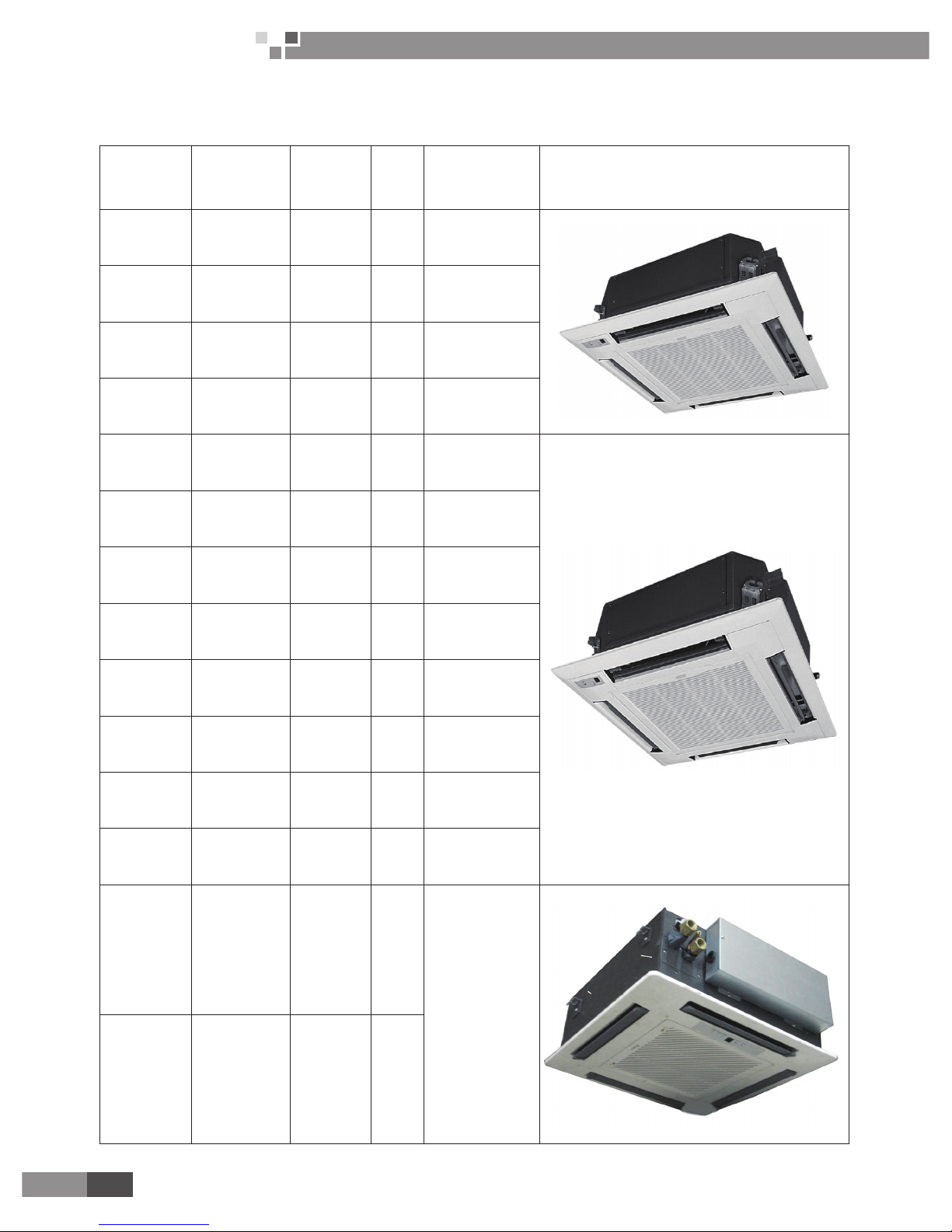
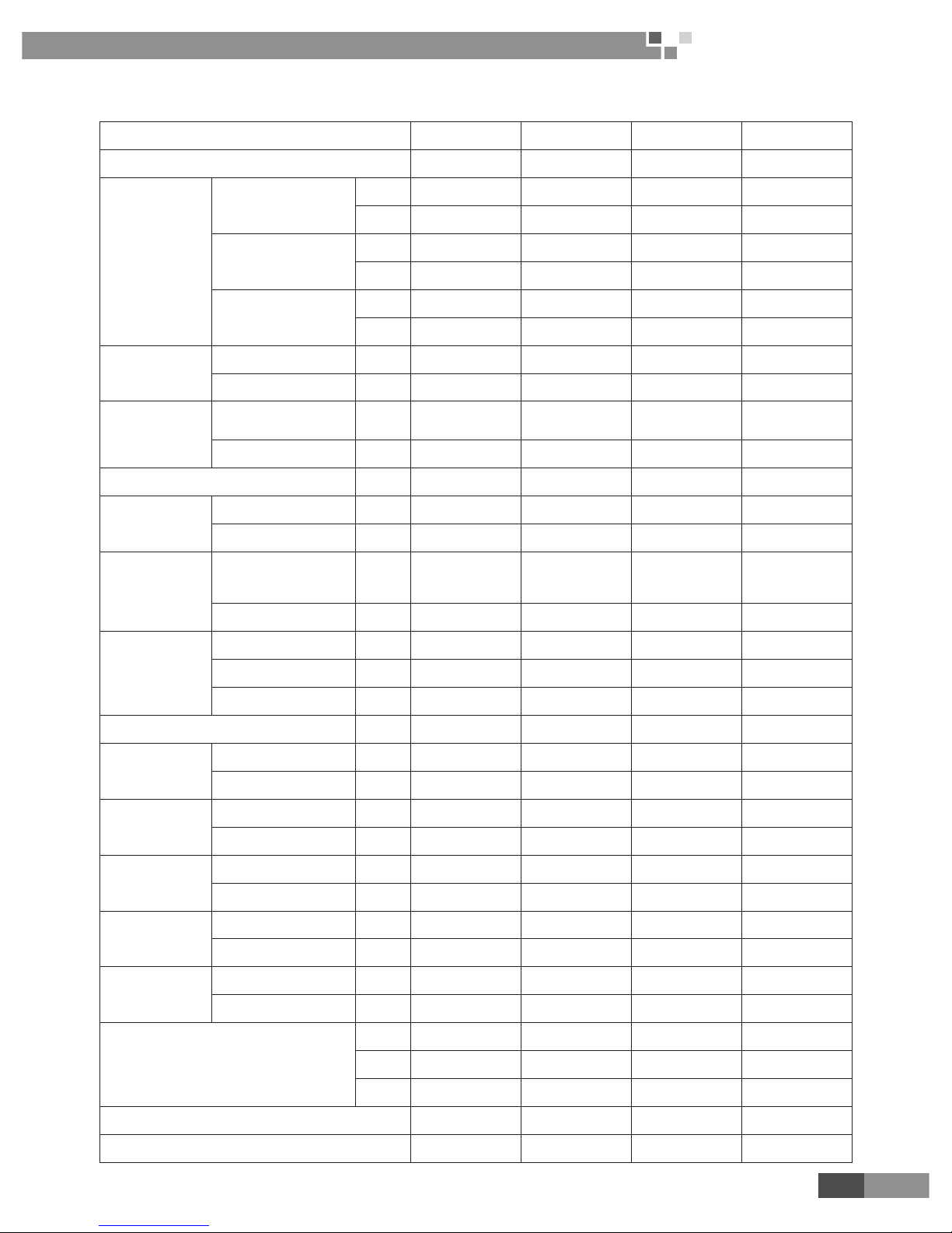
1. MODELS LIST
Model Name Product Code
Cooling
Capacity
(W)
Air ow
Volume
(m3/h)
Power Supply
(V, Ph, Hz)
Remarks
FP-8XD-E EM52000051 4600/7500 850 220-240V~ 50Hz
FP-8XD/A-E EM5200045010 4640/7500 850 220-240V~ 50Hz
FP-10XD-E EM52000061 5400/9100 1020 220-240V~ 50Hz
FP-10XD/A-E EM5200046010 5400/9100 1020 220-240V~ 50Hz
FP-12.5XD-E EM52000031 6700/10500 1270 220-240V~ 50Hz
FP-12.5XD/A-E EM5200047010 6700/10500 1250 220-240V~ 50Hz
FP-14XD-E EM52000071 7700/11200 1560 220-240V~ 50Hz
FP-14XD/A-E EM5200048010 7740/11200 1430 220-240V~ 50Hz
FP-16XD-E EM52000081 8700/12900 1640 220-240V~ 50Hz
FP-16XD/A-E EM5200049010 8700/12900 1640 220-240V~ 50Hz
FP-18XD-E EM52000041 9600/14600 1850 220-240V~ 50Hz
FP-18XD/A-E EM5200050010 9600/14600 1800 220-240V~ 50Hz
FP-51XD-E EM52000011 3000/4000 510
220-240V~ 50Hz
FP-68XD-E EM52000021 3500/5000 680
Page 5
3
Cassette Type Fan Coil
Unit Service Manual
PRODUCT
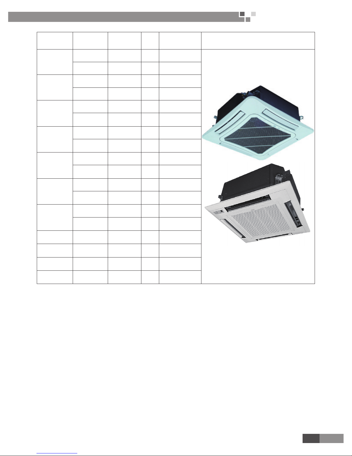
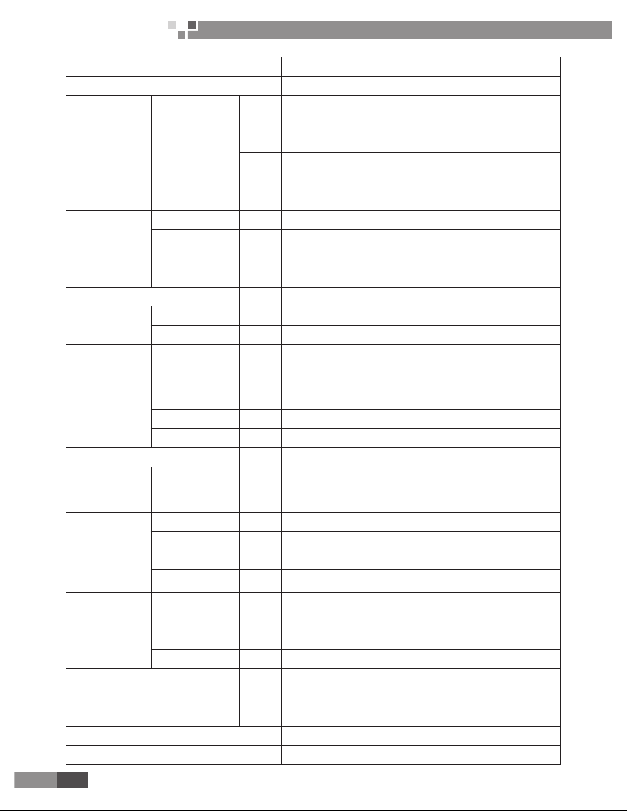
Model Name Product Code
Cooling/Heating
Capacity
(W)
Air ow
Volume
(m3/h)
Power Supply
(V, Ph, Hz)
Remarks
FP-85XD/B-T
EM520N0930 4150/5600 800 220-240V~ 50Hz
EM520N0940 4160/7800 780 208-230V~ 60Hz
FP-102XD/B-T
EM520N0910 500/6500 1020 220-240V~ 50Hz
EM520N0920 540/9000 1020 208-230V~ 60Hz
FP-125XD/B-T
EM520N0890 6000/7800 1180 220-240V~ 50Hz
EM520N0900 6300/10000 1130 208-230V~ 60Hz
FP-140XD/B-T
EM520N0870 8000/9000 1400 220-240V~ 50Hz
EM520N0880 8000/12000 1350 208-230V~ 60Hz
FP-160XD/B-T
EM520N0850 8700/10000 1550 220-240V~ 50Hz
EM520N0860 9000/14000 1550 208-230V~ 60Hz
FP-180XD/B-T
EM520N0830 9500/11000 1800 220-240V~ 50Hz
EM520N0840 10000/16000 1800 208-230V~ 60Hz
FP-200XD/B-T
EM520N0810 1300/14600 2000 220-240V~ 50Hz
EM520N0820 1300/19000 2000 208-230V~ 60Hz
FP-68XDT/B-K EM520N0990 3500/6000 680 220-240V~ 50Hz
FP-85XDT/B-K EM520N0960 4100/6800 850 220-240V~ 50Hz
FP-125XDT/B-K EM520N0970 6000/9500 1250 220-240V~ 50Hz
FP-180XDT/B-K EM520N0980 8000/13000 1800 220-240V~ 50Hz
Page 6
4
Cassette Type Fan Coil
Unit Service Manual
PRODUCT
2. NOMENCLATURE OF THE UNIT
FP - □ □ □ / □ - □
1 2 3 4 5 6
NO. Description Options
1 Fan coil Fan coil unit
2 Air ow volume Number×10 m
3
/h(FP-51XD-E;FP-68XD-E);Number×100 m3/h(8,10,12.5,14,16,18)
3 Structure type XD-Cassette Type
4 Pipes type Default- 2 pipes; T-4 pipes
5 Design Sequence Arranged by A, B,C…
6 Power code E-220-240V~ 50Hz;T-220-240V~ 50Hz, 208-230V~ 60Hz; K-220-240V~ 50Hz
3. FUNCTION
1. Novel pattern: the exposed skin plates of unit looks so elegant and luxurious that they can be taken as
the indoor decorations.
2. Compact design: A large number of non-metallic materials have been used, so that the body of the unit
is quite light-weight and thin, which makes the unit looks sensuous.
3. Low noise: Dynamic principles have been adopted for the design of the fan blades so as to make sure
the air volume is enough and running noise is considerably low.
4. Durable lter screen: The durable lter screen shares a cleaning cycle 20 times longer than that of the
conventional lter screen, needless to clean it frequently.
5. Microcomputer control: The unit is able to automatically adjust the fan speed in accordance with the
indoor ambient temperature to meet a wide range of users’ requirements.
6. Small height of the unit, saving much installation space
7. Large cooling (heating) capacity, low noise, three-speed motor which can adjust the air volume and
meet a wide range of users’ requirements.
8. Excellent material, stringent process control, which guarantee the hi-quality and long life of the unit.
9. Die-formed drain pan, entirely bonded insulating material, carefree about the condensate water.
Page 7
5
Cassette Type Fan Coil
Unit Service Manual
PRODUCT
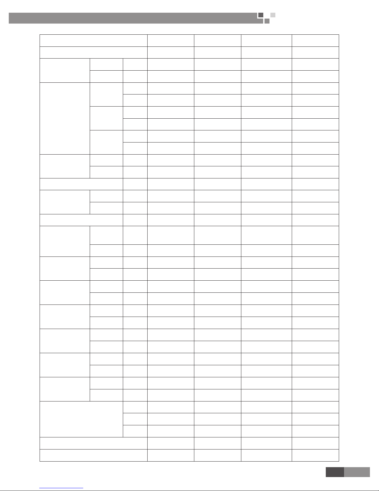
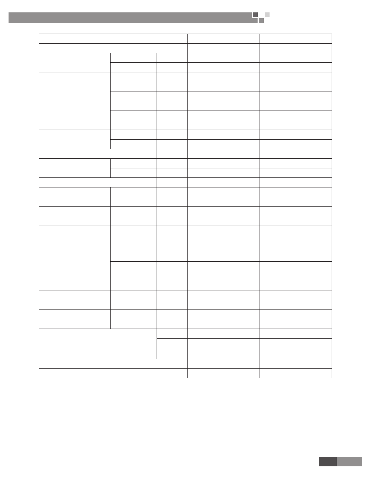
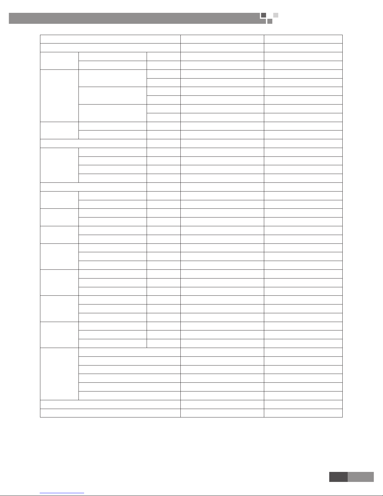
4. PRODUCT DATA
Model FP-8XD/A-E FP-10XD/A-E FP-12.5XD/A-E FP-14XD/A-E
Code EM5200045010 EM5200046010 EM5200047010 EM5200048010
Air ow volume
High
CFM 500 600 735 841
m
3
/h 850 1020 1250 1430
Medium
CFM 375 464 606 802
m
3
/h 637 789 1030 1363
Low
CFM 303 362 538 705
m
3
/h 515 615 915 1200
Capacity
Cooling W 4640 5400 6700 7740
Heating W 7500 9100 10500 11200
Power system
Type V-Ph-Hz 220-240V~ 50Hz 220-240V~ 50Hz 220-240V~ 50Hz 220-240V~ 50Hz
Input W 100 100 150 140
Exterior static pressure Pa 0 0 0 0
Water system
Water ow volume m
3
/h 0.829 0.964 1.196 1.382
Pressure drop kPa 15 25 25 30
Coil
Type -
Aluminum n-
copper tube
Aluminum n-
copper tube
Aluminum n-
copper tube
Aluminum n-
copper tube
Operating pressure MPa ≤1.6MPa ≤1.6MPa ≤1.6MPa ≤1.6MPa
Motor
Type - FN35B FN35B FN35B FN50T
Capacitor µF 2.5 3.5 3.5 2.5
Power output W 35 35 35 50
Sound pressure level dB(A) 46 46 47 52
Connection
pipe size
Water inlet &outlet inch G3/4" G3/4" G3/4" G3/4"
Condensing water drain mm 32 32 32 32
Outline dimension
(W×D×H)
Body mm 840×840×240 840×840×240 840×840×240 840×840×320
Panel mm 960×960×60 960×960×60 960×960×60 960×960×60
Package dimension
(W×D×H)
Body mm 960×960×310 960×960×310 960×960×310 960×960×394
Panel mm 1040×1025×115 1040×1025×115 1040×1025×115 1040×1025×115
Net weight
Body kg 27 27 27 33
Panel kg 6.5 6.5 6.5 6.5
Gross weight
Body kg 35 35 35 42
Panel kg 10 10 10 10
Loading quantity
20'GP 84 84 84 72
40'GP 168 168 168 120
40'HQ 192 192 192 144
Wired remote controller Z5K351/Z4E351B Z5K351/Z4E351B Z5K351/Z4E351B Z5K351/Z4E351B
Wireless remote controller YB1F2(X-FAN) YB1F2(X-FAN) YB1F2(X-FAN) YB1F2(X-FAN)
Page 8
6
Cassette Type Fan Coil
Unit Service Manual
PRODUCT
Model FP-16XD/A-E FP-18XD/A-E
Code EM5200049010 EM5200050010
Air ow volume
High
CFM 965 1060
m
3
/h 1640 1800
Medium
CFM 853 1035
m
3
/h 1460 1760
Low
CFM 781 932
m
3
/h 1327 1584
Capacity
Cooling W 8700 9600
Heating W 12900 14600
Power system
Type V-Ph-Hz 220-240V~ 50Hz 220-240V~ 50Hz
Input W 150 155
Exterior static pressure Pa 0 0
Water system
Water ow volume m
3
/h 1.554 1.714
Pressure drop kPa 30 30
Coil
Type - Aluminum n-copper tube Aluminum n-copper tube
Operating pressure MPa ≤1.6MPa ≤1.6MPa
Motor
Type - FN50T FN50T
Capacitor µF 4.5 4.5
Power output W 50 50
Sound pressure level dB(A) 53 54
Connection pipe size
Water inlet &outlet inch G3/4" G3/4"
Condensing water drain mm 32 32
Outline dimension
(W×D×H)
Body mm 840×840×320 840×840×320
Panel mm 960×960×60 960×960×60
Package dimension
(W×D×H)
Body mm 960×960×394 960×960×394
Panel mm 1040×1025×115 1040×1025×115
Net weight
Body kg 33 33
Panel kg 6.5 6.5
Gross weight
Body kg 42 42
Panel kg 10 10
Loading quantity
20'GP 72 72
40'GP 120 120
40'HQ 144 144
Wired remote controller Z5K351/Z4E351B Z5K351/Z4E351B
Wireless remote controller YB1F2(X-FAN) YB1F2(X-FAN)
Page 9
7
Cassette Type Fan Coil
Unit Service Manual
PRODUCT
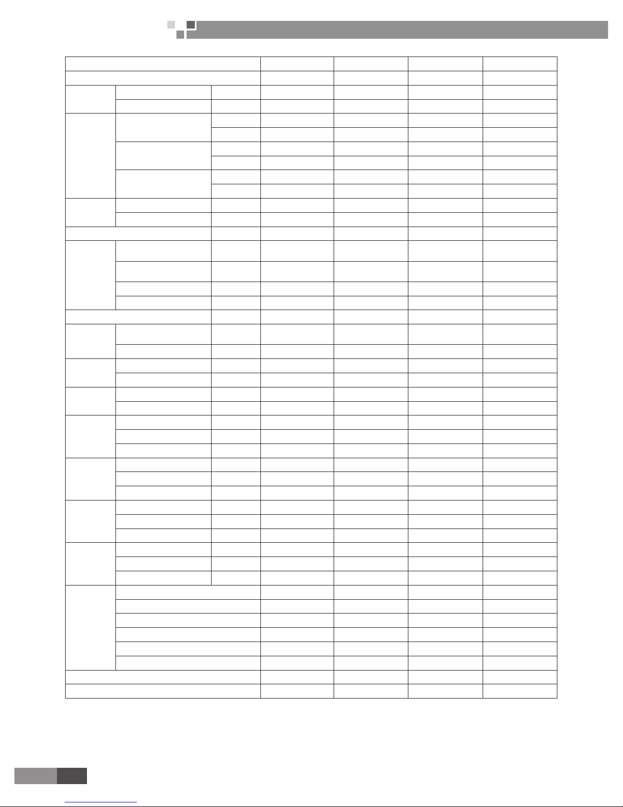
Model FP-8XD-E FP-10XD-E FP-12.5XD-E FP-14XD-E
Code EM52000051 EM52000061 EM52000031 EM52000071
Power system
Type V-Ph-Hz 220-240V~ 50Hz 220-240V~ 50Hz 220-240V~ 50Hz 220-240V~ 50Hz
Input W 100 100 150 140
Air ow volume
High
CFM 500 600 735 840
m
3
/h 850 1020 1250 1430
Medium
CFM 375 464 606 802
m
3
/h 638 789 1030 1363
Low
CFM 303 363 538 705
m
3
/h 515 617 914 1198
Capacity
Cooling W 4640 5400 6700 7740
Heating W 7500 9100 10500 11200
Electric heater rated power W 1400 1400 1400 1400
Water system
Water ow
volume
m
3
/h 0.81 0.95 1.18 1.36
Pressure
drop
kPa 15 25 25 25
Sound pressure level dB(A) 46 46 47 52
Coil
Type -
Aluminum n-
copper tube
Aluminum n-
copper tube
Aluminum n-
copper tube
Aluminum n-
copper tube
Operating
pressure
MPa ≤1.6MPa ≤1.6MPa ≤1.6MPa ≤1.6MPa
Motor
Type - FN35B FN35B FN35B FN50T
Capacitor µF 2.5 3.5 3.5 2.5
Connection pipe size
Water inlet
&outlet
inch G3/4" G3/4" G3/4" G3/4"
Condensing
water drain
mm 32 32 32 32
Outline dimension
(W×D×H)
Body mm 840×840×240 840×840×240 840×840×240 840×840×320
Panel mm 960×960×60 960×960×60 960×960×60 960×960×60
Package dimension
(W×D×H)
Body mm 960×960×310 960×960×310 960×960×310 960×960×394
Panel mm 1040×1025×115 1040×1025×115 1040×1025×115 1040×1025×115
Net weight
Body kg 30 30 30 38
Panel kg 6.5 6.5 6.5 6.5
Gross weight
Body kg 38 38 38 46
Panel kg 10 10 10 10
Loading quantity
20'GP 61 61 51 51
40'GP 11 6 11 6 116 93
40'HQ 133 133 133 112
Wired remote controller Z5K351/Z4E351B Z5K351/Z4E351B Z5K351/Z4E351B Z5K351/Z4E351B
Wireless remote controller YB1F2(X-FAN) YB1F2(X-FAN) YB1F2(X-FAN) YB1F2(X-FAN)
Page 10
8
Cassette Type Fan Coil
Unit Service Manual
PRODUCT
Model FP-16XD-E FP-18XD-E
Code EM52000081 EM52000041
Power system
Type V-Ph-Hz 220-240V~ 50Hz 220-240V~ 50Hz
Input W 160 155
Air ow volume
High
CFM 965 1059
m
3
/h 1640 1800
Medium
CFM 853 1035
m
3
/h 1450 1760
Low
CFM 781 932
m
3
/h 1328 1584
Capacity
Cooling W 8700 9600
Heating W 12900 14600
Electric heater rated power W 1400 1400
Water system
Water ow volume m
3
/h 1.53 1.68
Pressure drop kPa 27 29
Sound pressure level dB(A) 53 54
Coil
Type - Aluminum n-copper tube Aluminum n-copper tube
Operating pressure MPa ≤1.6MPa ≤1.6MPa
Motor
Type - FN50T FN50T
Capacitor µF 4.5 4.5
Connection pipe size
Water inlet &outlet inch G3/4" G3/4"
Condensing water drain mm 32 32
Outline dimension
(W×D×H)
Body mm 840×840×320 840×840×320
Panel mm 960×960×60 960×960×60
Package dimension
(W×D×H)
Body mm 960×960×394 960×960×394
Panel mm 1040×1025×115 1040×1025×115
Net weight
Body kg 38 38
Panel kg 6.5 6.5
Gross weight
Body kg 46 46
Panel kg 10 10
Loading quantity
20'GP 51 51
40'GP 93 93
40'HQ 11 2 112
Wired remote controller Z5K351/Z4E351B Z5K351/Z4E351B
Wireless remote controller YB1F2(X-FAN) YB1F2(X-FAN)
Page 11
9
Cassette Type Fan Coil
Unit Service Manual
PRODUCT
Model FP-51XD-E FP-68XD-E
Code EM52000011 EM52000021
Power system
Type V-Ph-Hz 220-240V~ 50Hz 220-240V~ 50Hz
Input W 49 56
Air ow volume
High
CFM 300 371
m
3
/h 510 680
Medium
CFM 247 318
m
3
/h 420 540
Low
CFM 206 265
m
3
/h 350 450
Capacity
Cooling W 3000 3500
Heating W 4000 5000
Electric heater rated power W - -
Water system
Water ow volume m
3
/h 0.49 0.616
Pressure drop kPa 5 9
Sound pressure level dB(A) 43 48
Coil
Type - Aluminum n-copper tube Aluminum n-copper tube
Operating pressure MPa ≤1.6MPa ≤1.6MPa
Motor
Type - FN11T FN11T
Capacitor µF 1 2.5
Connection pipe size
Water inlet &outlet inch G3/4" G3/4"
Condensing
water drain
mm 25 25
Outline dimension (W×D×H)
Body mm 600×600×230 600×600×230
Panel mm 650×650×50 650×650×50
Package dimension (W×D×H)
Body mm 848×678×310 848×678×310
Panel mm 730×670×102 730×670×102
Net weight
Body kg 19.3 19.3
Panel kg 5 5
Gross weight
Body kg 27 27
Panel kg 6 6
Loading quantity
20'GP 114 114
40'GP 216 216
40'HQ 256 256
Wired remote controller Z5K351 Z5K351
Wireless remote controller YB1F2(X-FAN) YB1F2(X-FAN)
Notes:
1. The water working temperature is from 7°C(44.6°F) to 60°C(140°F).
2. The temperature exchange efficiency and enthalpy exchange efficiency are tested under these
testing conditions as below:
(1) Cooling efciency: air 27°C(80.6°F) DB, 19.5°C(67.1°F) WB, water temperature in 7°C(44.6°F),water out 12°C(53.6°F).
(2) Heating capacity: air 21°C(69.8°F) DB, Water temperature intake 60°C(140°F), the water-ow volume is same as
Cooling capacity.
Page 12
10
Cassette Type Fan Coil
Unit Service Manual
PRODUCT
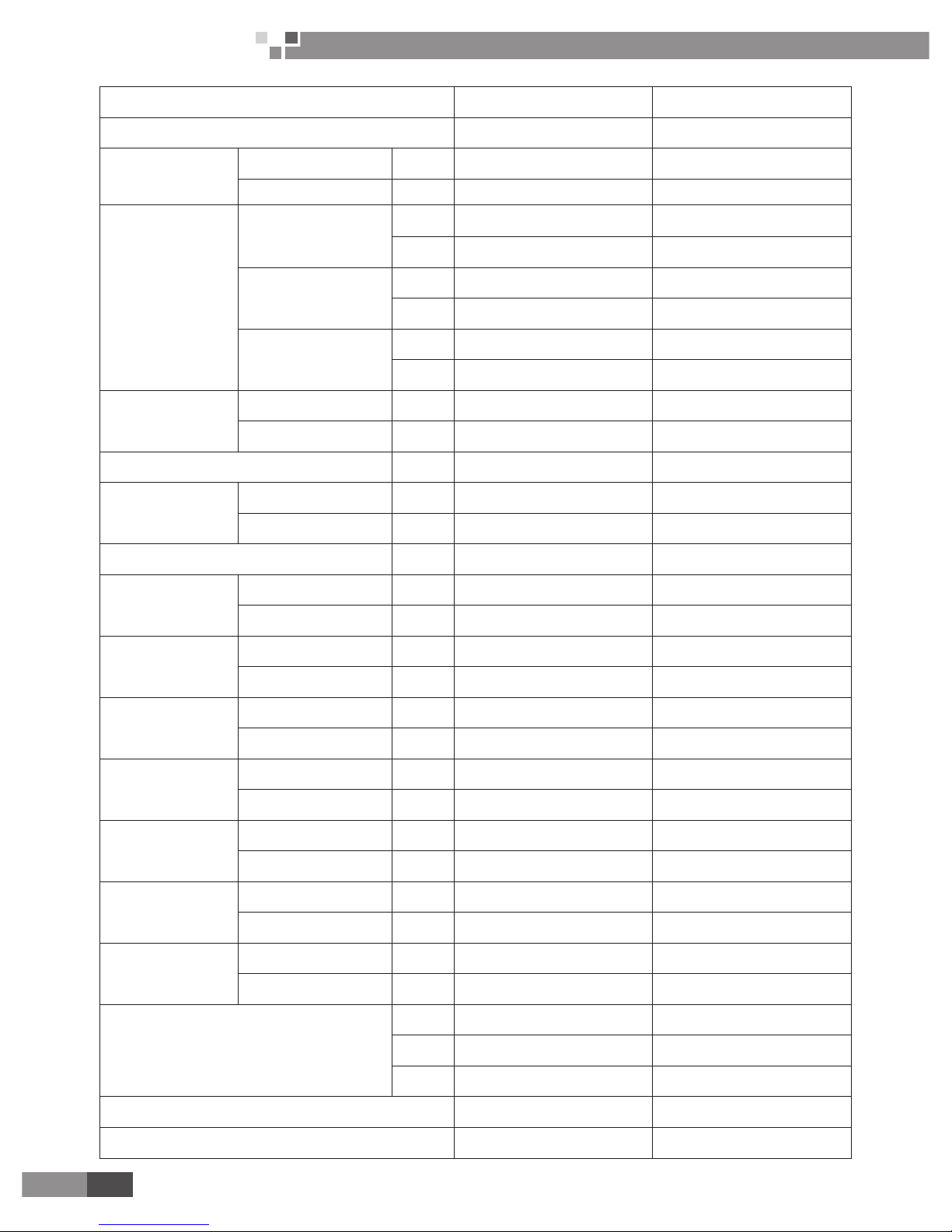
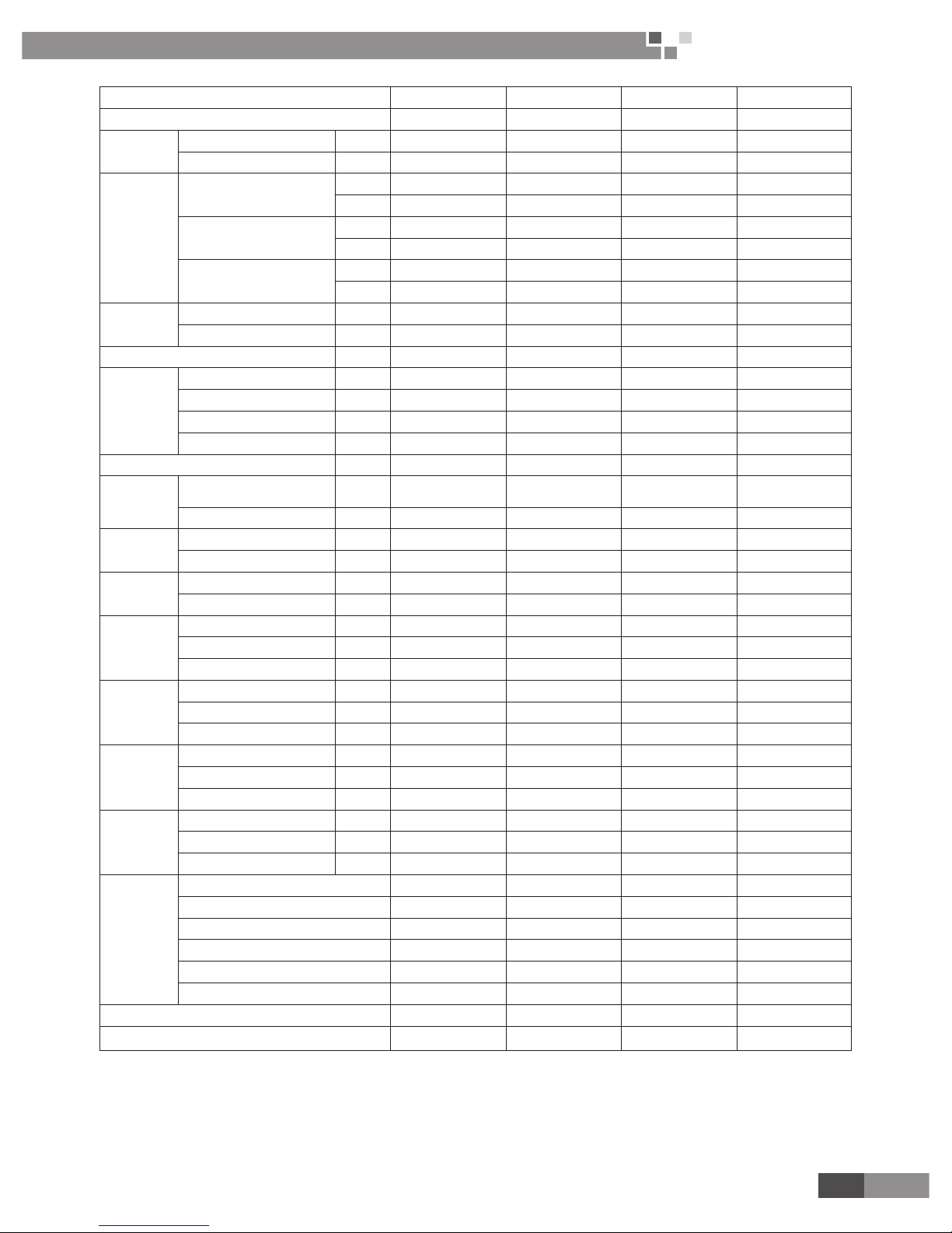
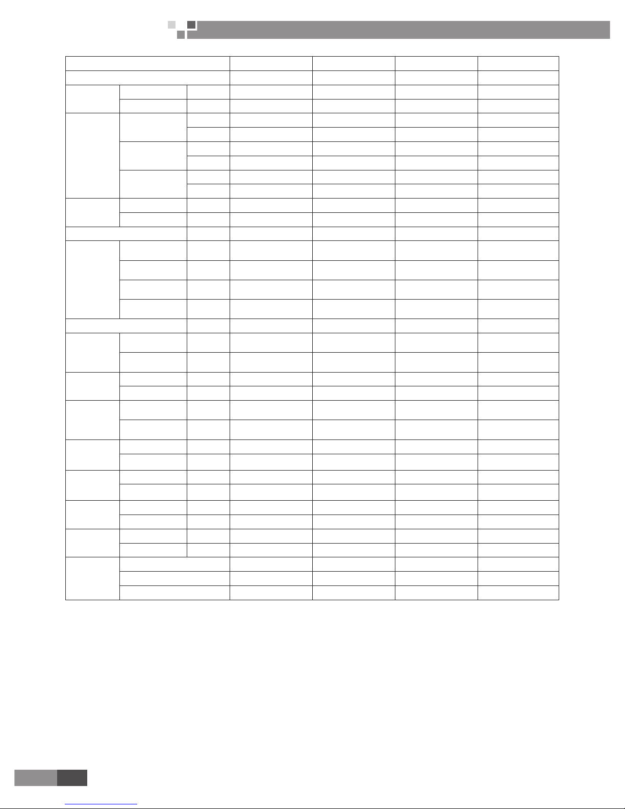
Model FP-85XD/B-T FP-85XD/B-T FP-102XD/B-T FP-102XD/B-T
Code EM520N0940 EM520N0930 EM520N0920 EM520N0910
Power
system
Type V-Ph-Hz 208-230V~ 60Hz 220-240V~ 50Hz 208-230V~ 60Hz 220-240V~ 50Hz
Input W 70 75 130 11 0
Air ow
volume
High
CFM 459 471 600 600
m
3
/h 780 800 1020 1020
Medium
CFM 371 382 599 599
m
3
/h 630 650 950 950
Low
CFM 324 324 529 529
m
3
/h 550 550 900 900
Capacity
Cooling W 4600 4500 5400 5000
Heating W 7800 5600 9000 6500
Electric heater rated power W - - - -
Water
system
Cooling water ow
volume
l/s 0.22 0.21 0.26 0.24
Heating water ow
volume
l/s 0.22 0.13 0.26 0.17
Cooling pressure drop kPa 27 24 48 36
Heating pressure drop kPa 24 8 47 13
Sound pressure level dB(A) 39 39 49 49
Coil
Type -
Aluminum n-
copper tube
Aluminum n-
copper tube
Aluminum n-
copper tube
Aluminum n-
copper tube
Operating pressure MPa ≤1.6MPa ≤1.6MPa ≤1.6MPa ≤1.6MPa
Motor
Type - FN35D-1 FN35D-1 FN35D-1 FN35D-1
Capacitor µF 2.00 2.00 5.00 5.00
Connection
pipe size
Water inlet &outlet inch G3/4" G3/4" G3/4" G3/4"
Condensing water drain mm 25 25 25 25
Outline
dimension
(W×D×H)
Body mm 840×840×190 840×840×190 840×840×190 840×840×190
Panel T01 mm 950×950×60 950×950×60 950×950×60 950×950×60
Panel TB03 mm 950×950×85 950×950×85 950×950×85 950×950×85
Package
dimension
(W×D×H)
Body mm 963×963×272 963×963×272 963×963×272 963×963×272
Panel T01 mm 1028×1043×130 1028×1043×130 1028×1043×130 1028×1043×130
Panel TB03 mm 1033×1038×133 1033×1038×133 1033×1038×133 1033×1038×133
Net weight
Body kg 25.0 25.0 25.0 25.0
Panel T01 kg 3.0 3.0 3.0 3.0
Panel TB03 kg 7 7 7 7
Gross
weight
Body kg 33.0 33.0 33.0 33.0
Panel T01 kg 5.0 5.0 5.0 5.0
Panel TB03 kg 11 11 11 11
Loading
quantity
20'GP(with panel T01) 57 57 57 57
40'GP (with panel T01) 133 133 133 133
40'HQ (with panel T01) 149 149 149 149
20'GP (with panel TB03) 56 56 56 56
40'GP (with panel TB03) 131 131 131 131
40'HQ (with panel TB03) 147 147 147 147
Wired remote controller Z4E351B Z4E351B Z4E351B Z4E351B
Wireless remote controller YB1FA(X-FAN) YB1FA(X-FAN) YB1FA(X-FAN) YB1FA(X-FAN)
Page 13
11
Cassette Type Fan Coil
Unit Service Manual
PRODUCT
Model FP-125XD/B-T FP-125XD/B-T FP-140XD/B-T FP-140XD/B-T
Code EM520N0900 EM520N0890 EM520N0880 EM520N0870
Power
system
Type V-Ph-Hz 208-230V~ 60Hz 220-240V~ 50Hz 208-230V~ 60Hz 220-240V~ 50Hz
Input W 130 82 140 120
Air ow
volume
High
CFM 665 694 794 824
m
3
/h 1130 1180 1350 1400
Medium
CFM 529 588 647 735
m
3
/h 900 1000 1100 1250
Low
CFM 441 529 588 676
m
3
/h 750 900 1000 1150
Capacity
Cooling W 6300 6000 8000 8000
Heating W 10000 7800 12000 9000
Electric heater rated power W - - - -
Water
system
Cooling water ow volume l/s 0.3 0.29 0.38 0.38
Heating water ow volume l/s 0.3 0.18 0.38 0.21
Cooling pressure drop kPa 27 24 33 30
Heating pressure drop kPa 28 9 29 10
Sound pressure level dB(A) 43 43 48 50
Coil
Type -
Aluminum n-
copper tube
Aluminum n-
copper tube
Aluminum n-
copper tube
Aluminum n-
copper tube
Operating pressure MPa ≤1.6MPa ≤1.6MPa ≤1.6MPa ≤1.6MPa
Motor
Type - FN35B-1 FN35B-1 FN35C FN35C
Capacitor µF 2.00 2.00 4.00 4.00
Connection
pipe size
Water inlet &outlet inch G3/4" G3/4" G3/4" G3/4"
Condensing water drain mm 25 25 25 25
Outline
dimension
(W×D×H)
Body mm 840×840×240 840×840×240 840×840×240 840×840×240
Panel T01 mm 950×950×60 950×950×60 950×950×60 950×950×60
Panel TB03 mm 950×950×85 950×950×85 950×950×85 950×950×85
Package
dimension
(W×D×H)
Body mm 963×963×325 963×963×325 963×963×325 963×963×325
Panel T01 mm 1028×1043×130 1028×1043×130 1028×1043×130 1028×1043×130
Panel TB03 mm 1033×1038×133 1033×1038×133 1033×1038×133 1033×1038×133
Net weight
Body kg 27.0 27.0 27.0 27.0
Panel T01 kg 3.0 3.0 3.0 3.0
Panel TB03 kg 7 7 7 7
Gross
weight
Body kg 34.0 34.0 35.0 35.0
Panel T01 kg 5.0 5.0 5.0 5.0
Panel TB03 kg 11 11 11 11
Loading
quantity
20'GP(with panel T01) 50 50 50 50
40'GP (with panel T01) 121 121 121 121
40'HQ (with panel T01) 134 134 134 134
20'GP (with panel TB03) 50 50 50 50
40'GP (with panel TB03) 117 117 11 7 117
40'HQ (with panel TB03) 133 133 133 133
Wired remote controller Z4E351B Z4E351B Z4E351B Z4E351B
Wireless remote controller YB1FA(X-FAN) YB1FA(X-FAN) YB1FA(X-FAN) YB1FA(X-FAN)
Page 14
12
Cassette Type Fan Coil
Unit Service Manual
PRODUCT
Model FP-160XD/B-T FP-160XD/B-T FP-180XD/B-T FP-180XD/B-T
Code EM520N0860 EM520N0850 EM520N0840 EM520N0830
Power system
Type
V-Ph-
Hz
208-230V~ 60Hz 220-240V~ 50Hz 208-230V~ 60Hz 220-240V~ 50Hz
Input W 140 125 160 160
Air ow volume
High
CFM 912 912 1059 1059
m
3
/h 1550 1550 1800 1800
Medium
CFM 765 824 824 853
m
3
/h 1300 1400 1400 1450
Low
CFM 676 765 765 794
m
3
/h 1150 1300 1300 1350
Capacity
Cooling W 9000 8700 10000 9500
Heating W 14000 10000 16000 11000
Electric heater rated power W - - - -
Water system
Cooling water ow
volume
l/s 0.43 0.42 0.48 0.45
Heating water ow
volume
l/s 0.43 0.23 0.48 0.27
Cooling pressure
drop
kPa 34 30 42 34
Heating pressure
drop
kPa 34 11 43 12
Sound pressure level dB(A) 51 51 50 50
Coil
Type -
Aluminum n-copper
tube
Aluminum n-copper
tube
Aluminum n-copper
tube
Aluminum n-copper
tube
Operating pressure MPa
≤
1.6MPa
≤
1.6MPa
≤
1.6MPa
≤
1.6MPa
Motor
Type - FN35C FN35C FN50K-1 FN50K-1
Capacitor µF 5.00 5.00 3.50 3.50
Connection
pipe size
Water inlet &outlet inch G3/4" G3/4" G3/4" G3/4"
Condensing water
drain
mm 25 25 25 25
Outline
dimension
(W×D×H)
Body mm 840×840×240 840×840×240 840×840×320 840×840×320
Panel T01 mm 950×950×60 950×950×60 950×950×60 950×950×60
Panel TB03 mm 950×950×85 950×950×85 950×950×85 950×950×85
Package
dimension
(W×D×H)
Body mm 963×963×325 963×963×325 963×963×409 963×963×409
Panel T01 mm 1028×1043×130 1028×1043×130 1028×1043×130 1028×1043×130
Panel TB03 mm 1033×1038×133 1033×1038×133 1033×1038×133 1033×1038×133
Net weight
Body kg 27.0 27.0 32.0 32.0
Panel T01 kg 3.0 3.0 3.0 3.0
Panel TB03 kg 7 7 7 7
Gross weight
Body kg 35.0 35.0 41.0 41.0
Panel T01 kg 5.0 5.0 5.0 5.0
Panel TB03 kg 11 11 11 11
Loading
quantity
20'GP(with panel T01) 50 50 42 42
40'GP (with panel T01) 121 121 98 98
40'HQ (with panel T01) 134 134 11 2 112
20'GP (with panel TB03) 50 50 42 42
40'GP (with panel TB03) 11 7 117 98 98
40'HQ (with panel TB03) 133 133 11 2 112
Wired remote controller Z4E351B Z4E351B Z4E351B Z4E351B
Wireless remote controller YB1FA(X-FAN) YB1FA(X-FAN) YB1FA(X-FAN) YB1FA(X-FAN)
Page 15
13
Cassette Type Fan Coil
Unit Service Manual
PRODUCT
Model FP-200XD/B-T FP-200XD/B-T
Code EM520N0820 EM520N0810
Power system
Type V-Ph-Hz 208-230V~ 60Hz 220-240V~ 50Hz
Input W 230 210
Air ow volume
High
CFM 1176 1176
m
3
/h 2000 2000
Medium
CFM 912 1000
m
3
/h 1550 1700
Low
CFM 735 853
m
3
/h 1250 1450
Capacity
Cooling W 13000 13000
Heating W 19000 14600
Electric heater rated power W - -
Water system
Cooling water ow volume l/s 0.62 0.62
Heating water ow volume l/s 0.62 0.25
Cooling pressure drop kPa 35 34
Heating pressure drop kPa 35 30
Sound pressure level dB(A) 55 55
Coil
Type - Aluminum n-copper tube Aluminum n-copper tube
Operating pressure MPa
≤
1.6MPa
≤
1.6MPa
Motor
Type - FN50K-2 FN50K-2
Capacitor µF 5.00 5.00
Connection
pipe size
Water inlet &outlet inch G3/4" G3/4"
Condensing water drain mm 25 25
Outline
dimension
(W×D×H)
Body mm 840×840×320 840×840×320
Panel T01 mm 950×950×60 950×950×60
Panel TB03 mm 950×950×85 950×950×85
Package
dimension
(W×D×H)
Body mm 963×963×409 963×963×409
Panel T01 mm 1028×1043×130 1028×1043×130
Panel TB03 mm 1033×1038×133 1033×1038×133
Net weight
Body kg 33.0 33.0
Panel T01 kg 3.0 3.0
Panel TB03 kg 7 7
Gross weight
Body kg 42.0 42.0
Panel T01 kg 5.0 5.0
Panel TB03 kg 11 11
Loading
quantity
20'GP(with panel T01) 42 42
40'GP (with panel T01) 98 98
40'HQ (with panel T01) 112 112
20'GP (with panel TB03) 42 42
40'GP (with panel TB03) 98 98
40'HQ (with panel TB03) 112 112
Wired remote controller Z4E351B Z4E351B
Wireless remote controller YB1FA(X-FAN) YB1FA(X-FAN)
Page 16
14
Cassette Type Fan Coil
Unit Service Manual
PRODUCT
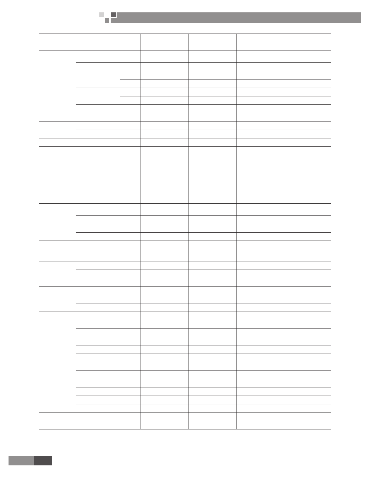
Model FP-68XDT/B-K FP-85XDT/B-K FP-125XDT/B-K FP-180XDT/B-K
Code EM520N0990 EM520N0960 EM520N0970 EM520N0980
Power
system
Type V-Ph-Hz 220-240V~ 50Hz 220-240V~ 50Hz 220-240V~ 50Hz 220-240V~ 50Hz
Input W 82 82 135 191
Air ow
volume
High
CFM 400 500 736 1059
m
3
/h 680 850 1250 1800
Medium
CFM 364 450 652 897
m
3
/h 618 764 1108 1525
Low
CFM 336 410 597 836
m
3
/h 571 697 1014 1421
Capacity
Cooling W 3500 4100 6000 8000
Heating W 6000 6800 9500 13000
Electric heater rated power W - - - -
Water
system
Cooling water
ow volume
l/s 0.21 0.24 0.29 0.44
Heating water
ow volume
l/s 0.17 0.19 0.27 0.36
Cooling
pressure drop
kPa 34.14 56.71 43.07 39.65
Heating
pressure drop
kPa 76.44 86.08 91.94 102.21
Sound pressure level dB(A) 39 40 43 50
Coil
Type -
Aluminum n-
copper tube
Aluminum n-
copper tube
Aluminum n-
copper tube
Aluminum n-
copper tube
Operating
pressure
MPa ≤1.6MPa ≤1.6MPa ≤1.6MPa ≤1.6MPa
Motor
Type - FN35D-1 FN35D-1 FN35B-1 FN50K-1
Capacitor µF 2.0 3.0 4.0 4.5
Connection
pipe size
Water inlet
&outlet
inch G3/4" G3/4" G3/4" G3/4"
Condensing
water drain
mm 25 25 25 25
Outline
dimension
(W×D×H)
Body mm 840×840×190 840×840×190 840×840×240 840×840×320
Panel TB03 mm 950×950×85 950×950×85 950×950×85 950×950×85
Package
dimension
(W×D×H)
Body mm 960×960×257 960×960×257 960×960×310 960×960×394
Panel TB03 mm 1033×1038×133 1033×1038×133 1033×1038×133 1033×1038×133
Net weight
Body kg 25.0 25.0 27.0 32.0
Panel TB03 kg 7 7 7 7
Gross weight
Body kg 33.0 33.0 34.0 41.0
Panel TB03 kg 11 11 11 11
Loading
quantity
20'GP (with panel TB03) 56 56 50 42
40'GP (with panel TB03) 131 131 121 98
40'HQ (with panel TB03) 147 147 134 112
Page 17

15
Cassette Type Fan Coil
Unit Service Manual
CONTROL
Testing condition:
For 60Hz :
The FCU designed for installation indoor. The environmental temperature is from 5°C to 43°C, water
working temperature is from 7°C to 60°C.
The temperature exchange efficiency and enthalpy exchange efficiency are tested under these testing
conditions as below:
1). Cooling capacity: air 27°C DB, 19.5°C WB, water temperature: intake 7°C, outlet12°C.
2).Heating capacity: air 21°C DB, Water temperature intake 60°C, the water-flow volume is same as
Cooling capacity .
3).Freeze-up : air 27°C DB, 24°C WB, water temperature intake 6°C, outlet 9°C.
4).Sound power level according to ISO 5151. Sound pressure level are calculated at the below of air-outlet
1m and 1m distance. The noise are tested before leaving factory.
For 50 Hz :
The FCU designed for installation indoor. The environmental temperature is from 5°C to 43°C, water
working temperature is from 7°C to 60°C.
The temperature exchange efficiency and enthalpy exchange efficiency are tested under these testing
conditions as below:
1).Cooling capacity: air 27°C DB , 19°C WB, water temperature intake 7°C, outlet 12°C.
2).Heating capacity: air 20°C DB , Water temperature intake 50°C, outlet 40°C.
3).Freeze-up : air 27°C DB, 24°C WB , water temperature 6°C intake , 10°C outlet .
4).Sound power level according to ISO 5151. Sound pressure level are calculated at the below of air-outlet
1m and 1m distance. The noise are tested before leaving factory.
For 4 pipes:
The FCU designed for installation indoor. The environmental temperature is from 5°C to 43°C, water
working temperature is from 7°C to 70°C.
The temperature exchange efciency and enthalpy exchange efciency are tested under these testing
conditions as below:
1).Cooling capacity: air 27°C DB , 19°C WB, water temperature intake 7°C, outlet 12°C.
2).Heating capacity: air 20°C DB , Water temperature intake 70°C, outlet 60°C.
3).Freeze-up : air 27°C DB, 24°C WB , water temperature 6°C intake , 10°C outlet .
4).Sound power level according to ISO 5151. Sound pressure level are calculated at the below of air-outlet
1m and 1m distance. The noise are tested before leaving factory.
Page 18

16
Cassette Type Fan Coil
Unit Service Manual
CONTROL
CONTROL
Page 19
17
Cassette Type Fan Coil
Unit Service Manual
CONTROL
CONTROL
1. WIRELESS REMOTE CONTROLLER
1.1 YB1F2(X-FAN)
Page 20
18
Cassette Type Fan Coil
Unit Service Manual
CONTROL
Page 21
19
Cassette Type Fan Coil
Unit Service Manual
CONTROL
Page 22

20
Cassette Type Fan Coil
Unit Service Manual
CONTROL
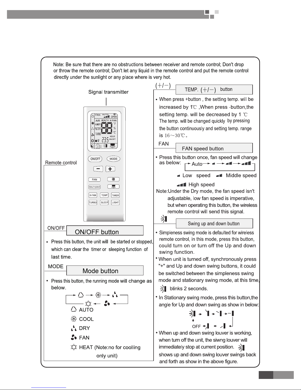
1.1.1 Guide for operation-general operation
① .
Press ON/OFF button to start the unit after poweringthe main unit on.(Note:
Power the unit on every time,the big-guide louver and small-guide louver will beclosed
rstly.)
② .
Press MODE button to select desired running mode.
③ .
Press +/ - button to set the desired temperature.(It is unnecessary to set the
temperature at AUTO mode)
④ .
Press FAN button to set fan speed, the AUTO FAN,LOW, MID or HIGH could
be selected.
⑤ .
Press
and button to set swing mode.
1.1.2 Guide for operation-optional operation
① .
Press SLEEP button, set the sleep mode.
② .
Press TIMER button, then press +/- button,
to set the cheduled timer on or timer off.
③ .
Press light button to control displayer light on or off.
④ .
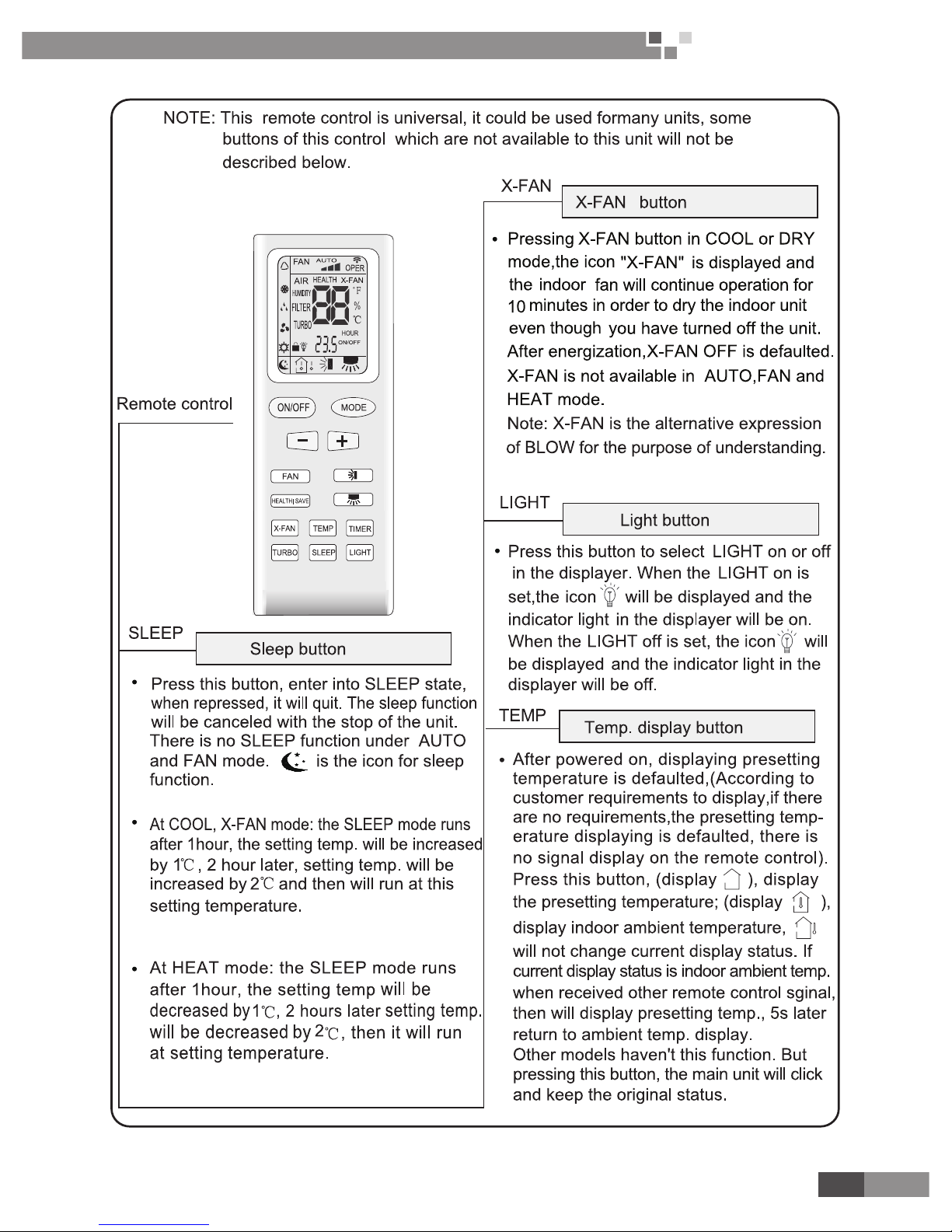
Press X-FAN button to set X-FAN function on or off.
⑤ .
Press turbo button to set this function on or off.
1.1.3 Introduction for special function
● About X-FAN function
This function indicates that moisture on evaporator of indoor unit will be blowed after the unit About X-FAN
functionis stopped to avoid mould.
Having set X-FAN function on: After turning off the unit by pressing ON/OFF buttonindoor fan will continue
running for about 10 min. at low speed. In this period, press X-FAN button to stop indoor fan directly.2. Having
set X-FAN function off: After turning off the unit by pressing ON/OFF button, the complete unit will be off directly.
● About AUTO RUN
When AUTO RUN mode is selected, the setting temperature will not be displayed on the LCD, the unit will
be in accordance with the room temp. automatically to select the suitable running method and to make ambient
comfortable.
● About turbo function
If start this function, the unit will run at super-high fan speed to cool or heat quickly so that the ambient
temp. approachs the preset temp. as soon as possible.
● About lock
Press +and - buttons simultaneously to lock or unlock the keyboard. If the remote controller is locked,
the icon
will be displayed on it, in which case, press any button, the mark will icker for three times. If the
keyboard is unlocked, the mark will disappear.
● About switch between Fahrenheit and Centigrade
Under status of unit off, press MODE and - buttons simultaneously to switch ºC and ºF.
● About new function of defrosting
It indicates: after starting this function by remote controller and the unit has been under defrost status, If
turn off the unit by remote controller, the unit will not stop defrosting until it is nished; if change setting mode by
remote controller, the function ,which is set last time, won't be carried out until defrosting nished.
Operation of this function on or off: If remote controller is under off status, press mode button and X-FAN
button simultaneously in order to enter or cancel this new function. If the unit is under defrost mode, dual eight
position on remote controller will display H1.If switch to heat mode, the position will display H1, which ickers
for 5s, in which case, press +/- button, H1 will disappear and setting temp. be displayed.
After remote controller is powered on, the new defrost function will be defaulted to be closed.
3.4 Changing batteries and notices
① .
Slightly to press the place with
along the arrowhead direction to push the
back cover of remote control.(As shown in Fig.① )
② .
Take out the old batteries, insert two AAA alkaline cells.(AS shown in
Fig
②③
.).
③ .
Attach the back cover of remote control.(Fig④)
Page 23

21
Cassette Type Fan Coil
Unit Service Manual
CONTROL
NOTE:
♦When changing the batteries, do not use the old ordifferent batteries,
otherwise, it can cause the malf-unction of the wireless remote control.
♦If the wireless remote control will not be used for along time, please take them
out, and don't let the leakage liquid damage the wireless remote control.
♦The operation should be in its receiving range.
♦It should be placed where is 1m away from the TVset or stereo sound sets.
♦If the remote control cannot operate normally, please take the batteries out,
and then reinsert it 30s later; it is also abnormal ,please replace the batteries.
♦If the main unit needs to be remote controlled, please aim remote control at the receiver of main unit in
orderto improve the receiving sensitivity of the main unit.When the remote control sends out signal, a mark will
icker for about 1s. The bell will ring if the main unit receives effective signal.
♦When the remote control sends out signal, a mark will icker for about 1s. The bell will ring if the
main unit receives effective signal.
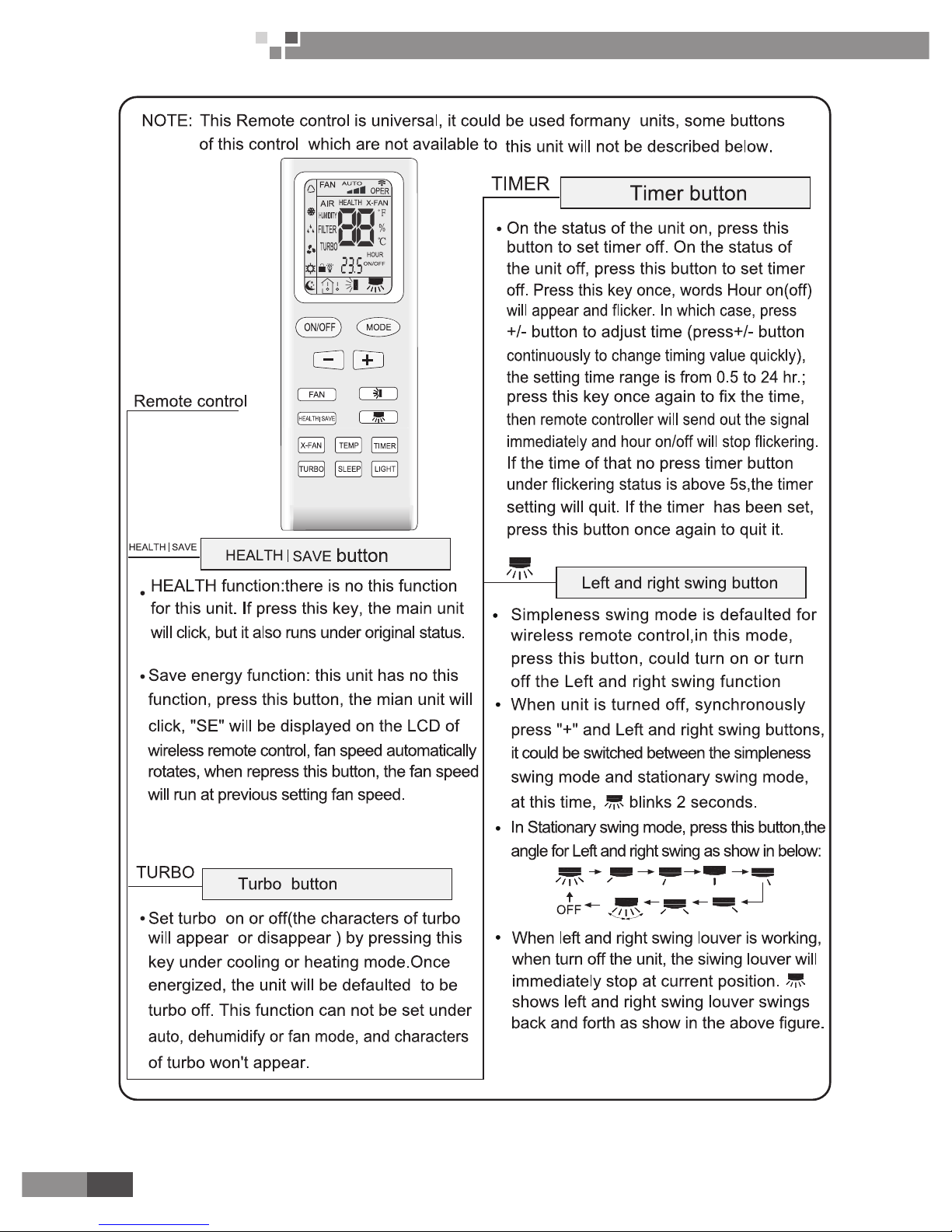
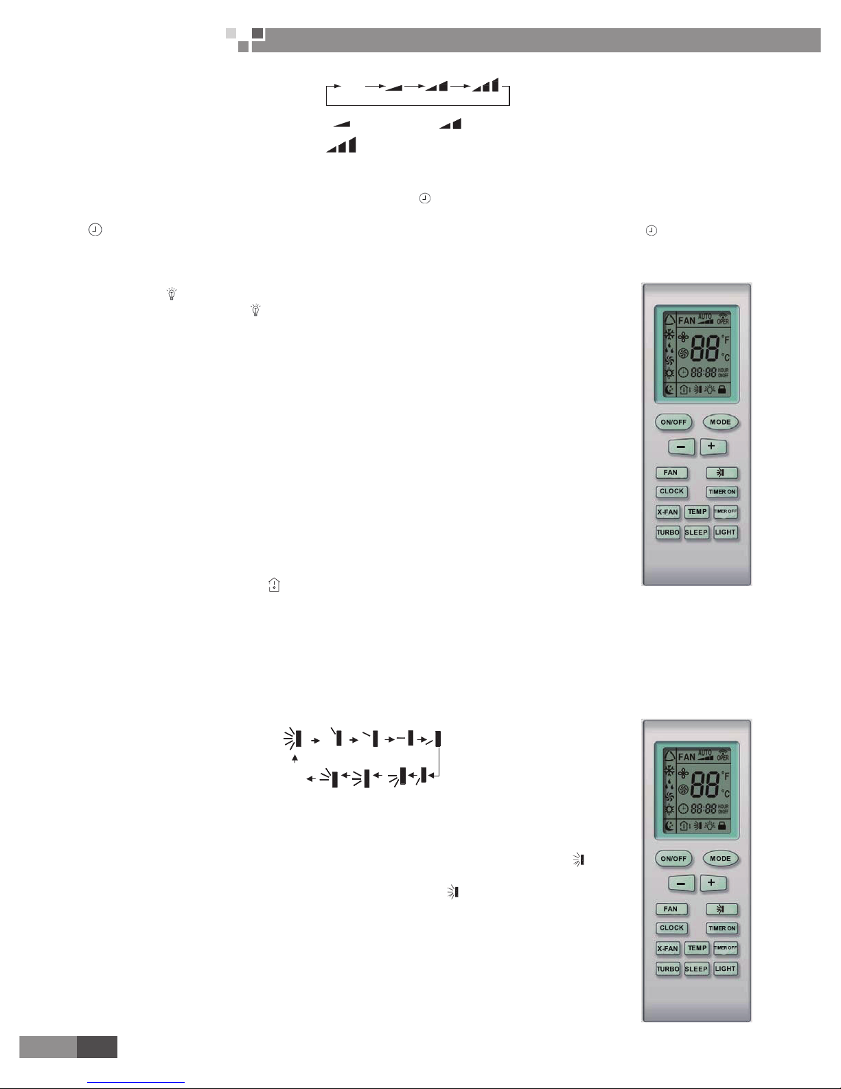
1.2 YB1FA(X-FAN)
Note:
♦ Be sure that there are no obstructions between receiver and remote control; Donot drop or throw the
remote control; Don't let any liquid drop into the remote control or leave the remote control under the sunlight or
place where is very hot.
♦This is a general remote control, it could be used for multiple types (functions) of air conditioners. For
some models without the functions specied here, we preserve the right to not to inform exclusively.
AUTO
COOL
DRY
FAN
HEAT
● ON/OFF button
Press ON/OFF button to turn on/off the unit. When the unit is turned off, the Timer, Sleep function will not
be retained in memory, but the time will be retained and is still displaying.
● MODE button
Press this button, Auto, Cool, Dry, Fan Heat mode can be selected circularly.
Auto mode is not available in this mode.
● SLEEP button
Press this button to select Sleep On/Sleep Off. If power is on, Sleep Off is default. If the unit is turned off,
the Sleep function setting will be not retained in memory. If Sleep function is on, the mark of Sleep will display.
In this mode, the time of timer can be adjusted. Under Fan and Auto modes, this function is not available.
● FAN button
Press this button, Auto, Low, Medium, High-speed can be circularly selected. After powered on, Auto fan
speed is default. Under Dehumidify mode, Low fan speed is default.
Page 24
22
Cassette Type Fan Coil
Unit Service Manual
PRODUCT
AUTO
Low
Medium
High
Note: Under the Dry mode, the fan speed isn't adjustable, low fan speed is default.
● CLOCK button
Press Clock button to set the time of clock. When blinks and displays, you can set the time by pressing
+ or - button. If no button is pressed within 10 seconds the remote will revert back to the normal display. Press
again to accept the setting. If it is set the rst time, 12:00 is the initial value. Note: If mark displays on the
LCD, it means it is the time of clock, if not, it is the time of timer.
● LIGHT button
Press this button to select LIGHT On/Off in the displayer. When the LIGHT On is
set,the mark will be displayed and the indicator light in the displayer will be on. When the
LIGHT Off is set, the mark will disappear and the indicator light will be off.The function is
not available for this mode.
● X-FAN button
Press this button to turn on/off the X-FAN function.
The function is not available for this mode.
● - button
Presetting temperature can be decrease the temperature by 1 degree Celsius
once. press and hold for more than two seconds so that we can change the temperature
continuously. The minimum and maximum setting range of the temperature is 16 to 30
degree Celsius.
● + button
Press this button increase the temperature by 1 degree Celsius once. Press and
hold for more than two seconds so that we can change the temperature continuously. The
minimum and maximum setting range of the temperature is 16 to 30 degree.
● TEMP button
Press this button to select the display of either indoor setting temperature or indoor
ambient temperature. When the indoor unit powered on rstly, setting temperature display
is default. Change status to
to display the ambient temperature. If received control
signal in 5 seconds, the display temp.will revert back to setting temperature. When unit is off, indoor setting
temperature display is default. Note: This function is only available for certain models.
● TURBO button
In Cool or Heat mode, press this button to turn on/off the Turbo function.
Note: This is a general remote control, it could be used for multiple types (functions) of air conditioners.
For some models without the functions specied here, we preserve the right to not to inform exclusively.
● SWING UP AND DOWN button
Press this button to adjust swing angle, which circularly changes as below:
OFF
This is a universal wireless remote controller; however, the unit covered in this manual
is only of the simplied SWING function. As a result, when the wireless remote controller is
energized initially with the unit under the OFF status, this simplied function should be set
by pressing the + button and the SWING button simultaneously, with the symbol
blinking
twice. Then, after the unit is turned on, this function can be activated or deactivated simply
by pressing the SWING button, with the displayed symbol indicating this function is on
and without this displayed symbol indicating this function is off.
● TIMER ON button
Press the TIMER ON button to set the timed On. Press +/- once to increase or
decrease the minute by 1 minute. If pressed and held for 2 seconds, the minute will
increase or decrease constantly by 1 minute. If held constantly for more than 5 seconds,
the minute will begin to change in every 10 minutes. Press TIMER ON again to accept the
setting and ON will show besides the time of clock meaning the setting succeeds. Press the
Page 25

23
Cassette Type Fan Coil
Unit Service Manual
PRODUCT
TIMER ON again to cancel the setting.
TIMER OFF button
Press the TIMER OFF button to set the timed off. The procedures are similar as above.
1.2.1 Operation of wireless remote control
1). Guide for operation – General operation
a. Press SLEEP button to set the sleep state.
b. Press TIME ON and TIME OFF button to scheduled the unit ON/OFF.
c. Press LIGHT button to control on and off the indicator board.(This function maybe
not available for some units.)
2). Guide for operation-Optional operation
a. After powered on, press ON/OFF button, the unit will start to run.
(Note: When it is powered off , the guide louver of main unit will close automatically.)
b. Press MODE button, select desired running mode ,or press COOL or HEAT mode to enter the
corresponding operation directly.
c. Press + or-button to set the desired temperature.
d. Press FAN button to set fan speed from AUTOFAN , LOW , MID and HIGH.
e. Press
button to select SWING mode.
f. Press +and - buttons simultaneously to lock or unlock the wireless remote control. If it is locked, the
mark will display; when pressing any button, the mark
will blink for three times but the air conditioner has no
respondence. If unlocked, the mark will disappear.
g. Switch between Fahrenheit and Centigrade.
When unit is under Off state, press MODE and – button simultaneously to switch between ºC and ºF.
1.2.2 Changing batteries and notices.
Slightly to press the place with , along the arrowhead direction to push the back
cover of wireless remote control. (As show in gure)
Take out the old batteries. (As show in gure.)
Insert two new AAA1.5V dry batteries, and pay attention to the polarity. (As show in
gure)
Attach the back cover of wireless remote control. (As show in gure)
NOTE:
♦The design of this unit conforms to the requirements of ISO5151 standard.
♦The air volume is measured at the 0Pa external static pressure.
♦Cooling (heating) capacity stated above is measured under nominal working
conditions corresponding to 0Pa external static pressure. The parameters are subject to
change with the improvement of products, in which case the values on the nameplate will
prevail.
Fig.24
Fig.25
Sketch map for
changing batteries
Page 26
24
Cassette Type Fan Coil
Unit Service Manual
PRODUCT
2. WIRED REMOTE CONTROLLER
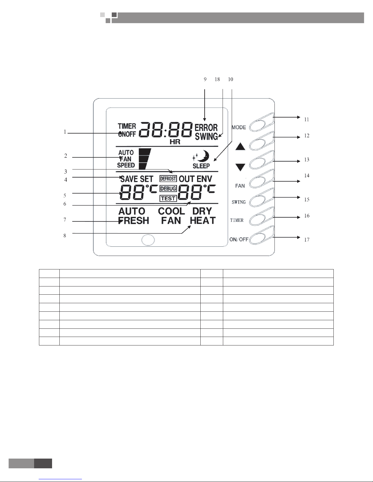
2.1 Introduction to Z5K351(optional)
NOTE: Never install the wired remote controller in a place where there is water leakage.
Avoid bumping, throwing, tossing or frequently opening the wired remote controller.
1 Time display 10 Sleep display
2 Fan speed display(Auto, High, Middle, Low) 11 MODE button
3 Defrosting display 12 Button for temp. increase
4 Saving state display 13 Button for temp. decrease
5 Set temp. display 14 FAN button
6 Ambient temp. display 15 SWING button
7 Fresh air display 16 TIMER button
8 Mode(COOL, DRY, FAN, AUTO) 17 ON/OFF button
9 Malfunction display 18 Display of Swing state
Page 27

25
Cassette Type Fan Coil
Unit Service Manual
PRODUCT
2.2 Introduction to Z4E351B (optional)
2.2.1 Symbols on the LCD
Introduction to the Symbols on the LCD.
No. Symbol Function Description
1
It indicates the swing function.
2
It indicates the function of air exchange. (It is unavailable for this wired controller.)
3
It indicates the sleeping status.
4
It indicates each running mode of the indoor unit (AUTO mode).
(It is unavailable for this wired controller. )
5
It indicates the “ Cool ” mode.
6
It indicates the “ Dry ” mode.
7
It indicates the “ Fan ” mode.
8
It indicates the “ Heat ” mode.
9
It indicates the defrosting mode. (It is unavailable for this wired controller.)
10
It indicates the gate control status.
11
It indicates the locking status.
12
It indicates the shield status. (It appears when all functions, or the function “On/Off ”, “
Temp ”, “ Mode ”, or “ Save ” is shielded through the Long-distance monitoring System.)
13
It indicates the current fan speed.
Page 28

26
Cassette Type Fan Coil
Unit Service Manual
PRODUCT
14
It indicates the memory function is activated, that is, the unit will
back to the previous set status after powered on again.
15
It indicates the turbo status.
16
It ashes animatedly when the unit is started and the ambient temperature is displayed.
17
It indicates the ambient temperature/set temperature.
18
It indicates the energy saving status.
19
It indicates that the auxiliary electric heater can be activated.
20 It indicates the blow function is activated.
21
It indicates the timer status.
22
It indicates the quiet operation status. (including two statuses, “ Quiet ” and “ Auto Quiet ”. )
Note: Symbols “ MASTER ” and “ CO
2
” will not displayed on the LCD of the wired controlled XK26.
2.2.2 Introduction to the Functions of the Press Keys
1
5 6 7 8
2 3
Introduction to the Functions of the Press Keys.
No. Press Bottoms Function Description
1 Enter/Cancel It is used to select the desired function or cancel the selected function.
2 ▲
(1) It is used to adjust the running temperature of the indoor unit among16~30℃.
(2) It is used to adjust the temperature under the energy saving condition among16~30
℃.
(3) It is used to adjust the timer among 0.5~24 hours.
(4) It is used to switch between the modes of “ Quiet ” and “Auto Quiet ”.
6 ▼
3 Fan There are four fan speed options, High, Medium, Low and Auto.
4 Mode
(1) It is used to set the mode of “ Cool ”,“ Dry ”, “ Fan ”, and “ Heat ”.
(2) When the “Save” function is being set, it is used to switch
between the mode options of “ Heat ” and “ Cool ”.
(3) When the “ Timer ” is being set, it is used to switch
between the options of “Unit On” and “Unit Off”.
5 Function
It is used to switch the functions of “Swing”, “Sleep”, “Turbo”,
“Save”, “E-Heater”, “Blow”, “Quiet”, etc.
7 Timer It is used to set the timer.
8 On/Off It is used to start/stop the indoor unit.
4 +2
Mode +▲
(MEMORY)
Under the “ Off ” status of the unit, press “Mode” and “▲” simultaneously for ve
seconds to activate or deactivate the “MEMORY” function. (once this function
is activated, the unit with power failure will resume the previous set status
after powered on again; otherwise it will go to the “Off ” status.)
2 +6
▲+▼
(LOCK)
Press “▲” and “▼” simultaneously for ve seconds to go to the lock
status, in which case the press on any other key will get no response. And
another press on “▲” and “▼” for ve seconds will quit this status.
5+ 7
Function +Timer
(Ambient Temperature
Sensor; Anti Cold/
Hot Air)
Under the “Off ” status of the unit, press “ Function ” and “ Timer ” simultaneously
for ve seconds to call out the debugging menu, after that press “ Mode ” to
select the desired submenu and press “▲”/“▼” to set the parameter, nally
press “ Enter/Cancel ” to save the setting and quit the setting status.
4 +6 Mode +▼
Under the “Off ” status of the unit, press “ Mode ” and “▼”simultaneously
for ve seconds to switch the Celsius scale and Fahrenheit scale.
Page 29

27
Cassette Type Fan Coil
Unit Service Manual
INSTALLATION
Page 30
28
Cassette Type Fan Coil
Unit Service Manual
INSTALLTION
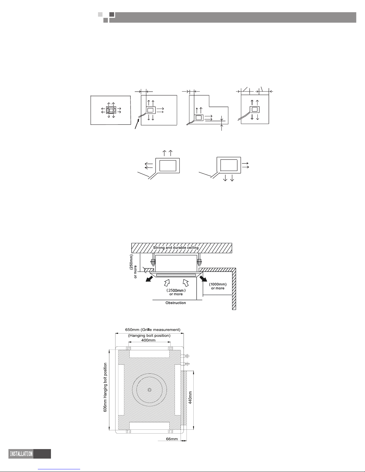
1. SELECTION THE MOUNTING POSITION
Especially, the installation place is very important for the fan coil unit because it is very difcult to move
from placc aftr the rst installation.
Decide the mounting position together with the customer as follows:
The discharge direction can be selected as shown below.
(4 directions)
(3 directions)
4''(100mm) or more
4''(100mm) or more
4''(100mm) or more
39''(1,000mm) or more
(2 directions)
(2 directions)
Piping position
Since 2 -way outlet causes performance problems, do not set it .
pipe
pipe
Install the indoor unit on a place having a sufcient strength so that it with stands against the weight of the
unit.
The inlet and outlet ports should not be obstructed; the air should be able to blow all over the room.
Leave the space required to service the air conditioner.
The ceiling rear height is 9-3/8 " inches(250mm) or more.
A place from where the air can be distributed evenly throughout the room by the unit.
A place from where drainage can be extracted outdoor easily.
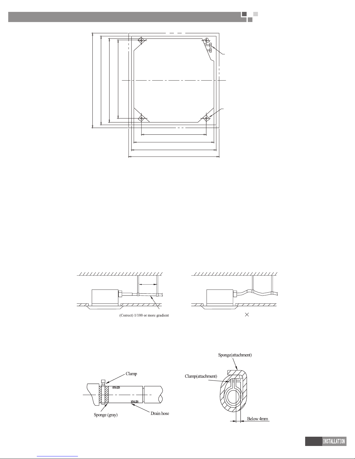
1.1Ceiling opening and suspension bolt (M l0) pitch emension
Be suitable for:
FP-51XD-E
FP-68XD-E
Page 31
29
Cassette Type Fan Coil
Unit Service Manual
680(Gaps between hoisting screw rods
)
840(Indoor unit )
890(Ceiling opening)
950 ( Decorated surface boards)
Hoisting screw (×4)
Water pipe
780(Gaps between hoisting screw rods)
840(Indoor unit)
890(Ceiling opening)
950 ( Decorated surface boards)
Be suitable for:
P-85XD/B-T; FP-102XD/B-T; FP-125XD/B-T; FP-140XD/B-T; FP-160XD/B-T; FP-180XD/B-T; FP-200XD/
B-T; FP-10XD–E; FP-12.5XD-E; FP-14XD-E; FP-16XD-E; FP-18XD-E;P-8XD/A-E; FP-10XD/A–E; FP-12.5XD/
A-E; FP-14XD/A-E; FP-16XD/A-E; FP-18XD/A-E; FP-85XD/B-T; FP-102XD/B-T; FP-125XD/B-T; FP-140XD/B-T;
FP-160XD/B-T; FP-180XD/B-T; FP-200XD/B-T; FP-68XDT/B-K; FP-85XDT/B-K; FP-125XDT/B-K; FP-180XDT/
B-K;
2. DRAINAGE PIPE
The diameter of the drain pipe should be greater than of equal to the diameter of the connecting pipe [vinyl
tube, pipe size: Outer diameter 25mm (outer dimension)].
Keep the drainage pipe short and sloping downwards at a gradient of at least 1/100 to prevent air pockets
from forming.
If the drainage hose cannot be sufciently set on, add a drainage raising pipe.
To keep the drainage hose from sagging, keep space between hanging hooks at 1~1.5m.
1-1.5m
(Wrong)
Use the drain hose and clamp attached. Insert the drain hose to the drain vent, and then tighten the clamp.
Entwine the big sponge on the clamp of drain hose to insulate heat.
Heat insulation should be done to indoor drain hose.
Page 32

30
Cassette Type Fan Coil
Unit Service Manual
3. PRECAUTIONS FOR DRAINAGE RAISING PIPE
The install height of the drain raising pipe should less than 280mm.
The drain raising pipe should form a upright angle with the unit, and distance to unit should not beyond
300mm.
3.1 Instruction
♦The slant gradient of the attached drain hose should be within 75mm so that the drain hole doesn’t has
to endure the unnecessary outside force.
♦Please install the drain hose according to the following process if several drain hoses join together.
♦The installation of the motorized valve should be done according as .Firstly connect one end of the
tube joint with the water inlet tube of the unit, then connect the other end with the motorized valve, and lastly
connect the motorized valve with the are nut . During the installation, both the torque wrench and the spanner
should be used and the moment of torque should be within 90 N.m. Besides, a secure connection should be
guaranteed.
Flare nut
Wiring interface
water inlet tube
Torque wrench
Thread fasten
Spanner
Valve
Tape
Water tube joint
♦Both the tube joint and the motorized valve are G3/4" threaded. Prior to the connection, it is
recommended to wrap the tacky tape on the thread for two or three cycles for better sealing effects .
♦After the tube joint, motorized valve, water inlet tube, water outlet tube are connected reliably, start the
Page 33

31
Cassette Type Fan Coil
Unit Service Manual
water pump of the outdoor unit to check if they leak or not.
♦What should be done lastly is wrapping sponge around the motorized valve and the tube for heat
insulation.
(1) For 2 pipes:
Body
Vavle
Intlet tube
Outlet tube
Pipe sleeve
HL-G3-3/4S
Powerr cord
(connecteddr with rther unit)
PE
WATER
VALVE
N
L
(2) For 4 pipes:
FCU
the FCU
Valve
PE
N
L
POWER
HOT WATER
COLD WATER
VALVE
VALVE
YV2
YV2
YV1
YV1
L
N
TERMINAL BOARD
♦Check the smoothness of drain after installation.
♦Check the drain state by imitating 600cc water slowly from the outlet vent or test hole.
♦Check the drain in the state of refrigerating after installation of the electric circuit.
Warning: Before obtaining access to terminals, all supply circuits must be disconnected.
Page 34

32
Cassette Type Fan Coil
Unit Service Manual
4. ELECTRIC WIRING
1. All eld supplied parts and materials must conform to local laws and regulations.
2. For electric wiring, refer to WIRING DIAGRAM attached to the unit body.
3. All wiring must be performed by a skilled technician.
4. A circuit breaker capable of shutting down power supply to the entire system and which have at least
mm contact separation in each jole must be installed in the xed wiring.
5. Earth properly.
6. Wiring must conform to national laws and regulations.
7. The xed wiring must be installed with a protector with no more that 30 mA leakage current.
8. If the supply cord is damaged, it must be replaced by the manufactory or its service agents or a
similarity qualied person in order to avoid a hazard.
4.1 Wiring of unit and the controller
4.1.1 Wiring of the unit
(1) For 2 pipes
Remove the control box lid, pull the wires inside through rubber bush and wiring according to the WIRING
DIAGRAM, then tighten it with clamp.
Wiring of the controller
♦Remove the control box lid, pull wires inside through rubber bush and connect to the controller.
♦Wrap the wire with sealing pad.
♦After wiring, tighten it with clamp and x the control box lid.
♦Heating and cooling: connect the rubber wire (5-cords) to the power supply terminal board in properly.
♦Cooling: connect the rubber wire (3-cords) to the power supply terminal board properly.
Precautions: Be sure to connect the unit at right poles.
(2) For 4 pipes
The "WIRING DIAGRAM" in the manual is reference. The correct wiring should agree with the "WIRING
DIAGRAM "on controller box of the unit.
1) Remove the control box lid (1). Pull the wires inside through rubber bush I and wiring according to the “
WIRING DIAGRAM ”, then tighten it with clamp.After wiring, tighten it with clamp and x the control box lid(1).
(2) .
2) When the wiring is completed, take a careful check and then start the water pump and unit to see if the
motorized valve works normally.
Page 35

33
Cassette Type Fan Coil
Unit Service Manual
Control box lid(1)
Control box lid(2)
Rubber bush I
Rubber bush II
Clamp
Seal here to avoid leakage
YV2 YV2
YV1 YV1
L
N
Power supply
Connected with water valve
Connected with user power
terminal board
Page 36
34
Cassette Type Fan Coil
Unit Service Manual
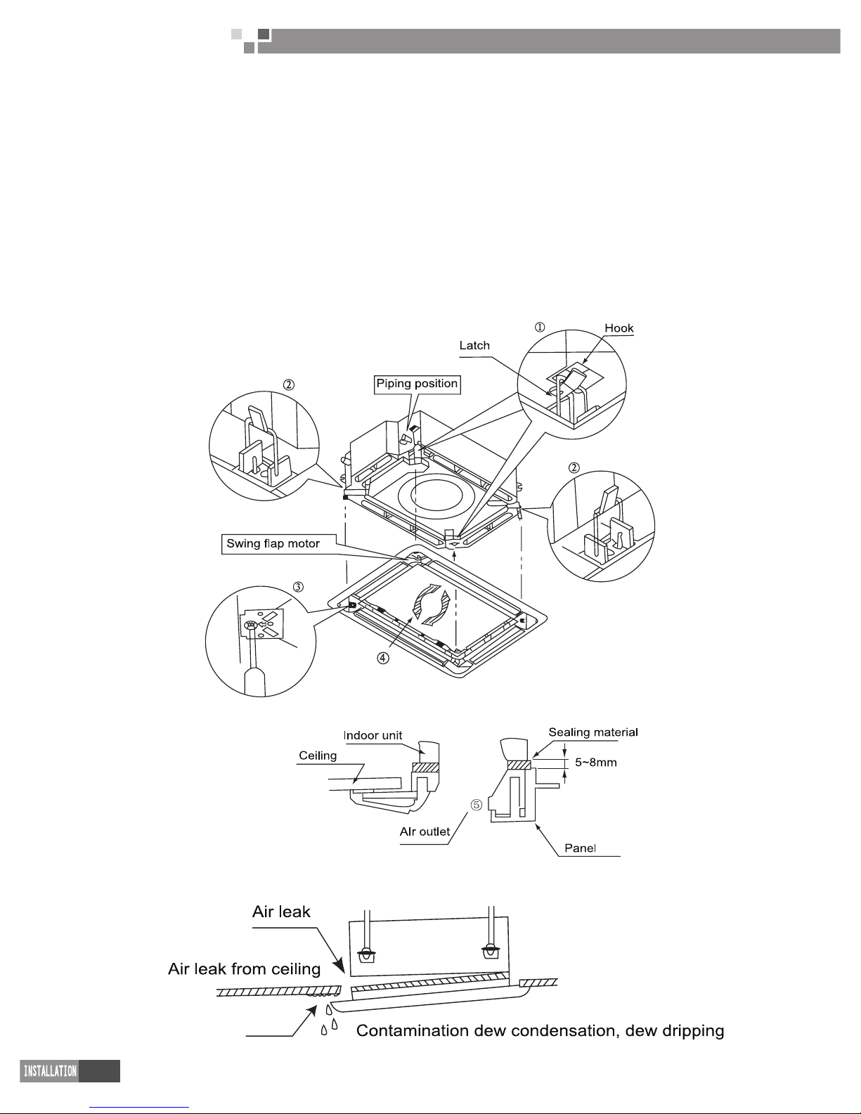
5. INSTALLATION OF PANEL
Set the panel to the unit body by matching the position of the swing ap motor of the decoration panel to
the piping position of the indoor unit as shown as below.
Install the decoration panel.
1. Hang the latch, which is located on the opposite side of the swing ap motor on the panel, temporarily
to the hook of the unit. (2 Positions)
2. Temporarily hang the remaining 2 latches to the hooks on the sides of the unit.(be careful not to let the
swing motor lead wire get caught in the sealing material.)
3. Screw all 4 hexagon head screws located right beneath the latches in approximately 15mm.(panel will
rise)
4. Adjust the panel by turning it to the arrowed direction in Fig.4 so that the ceiling opening is completely
covered.
5. Tighten the screws until the thickness of the sealing material between the panel and the unit.
6. Body is reduced to 5~8 mm.
5.1 Precautions
Improper screwing of the screws may cause the troubles.
Page 37
35
Cassette Type Fan Coil
Unit Service Manual
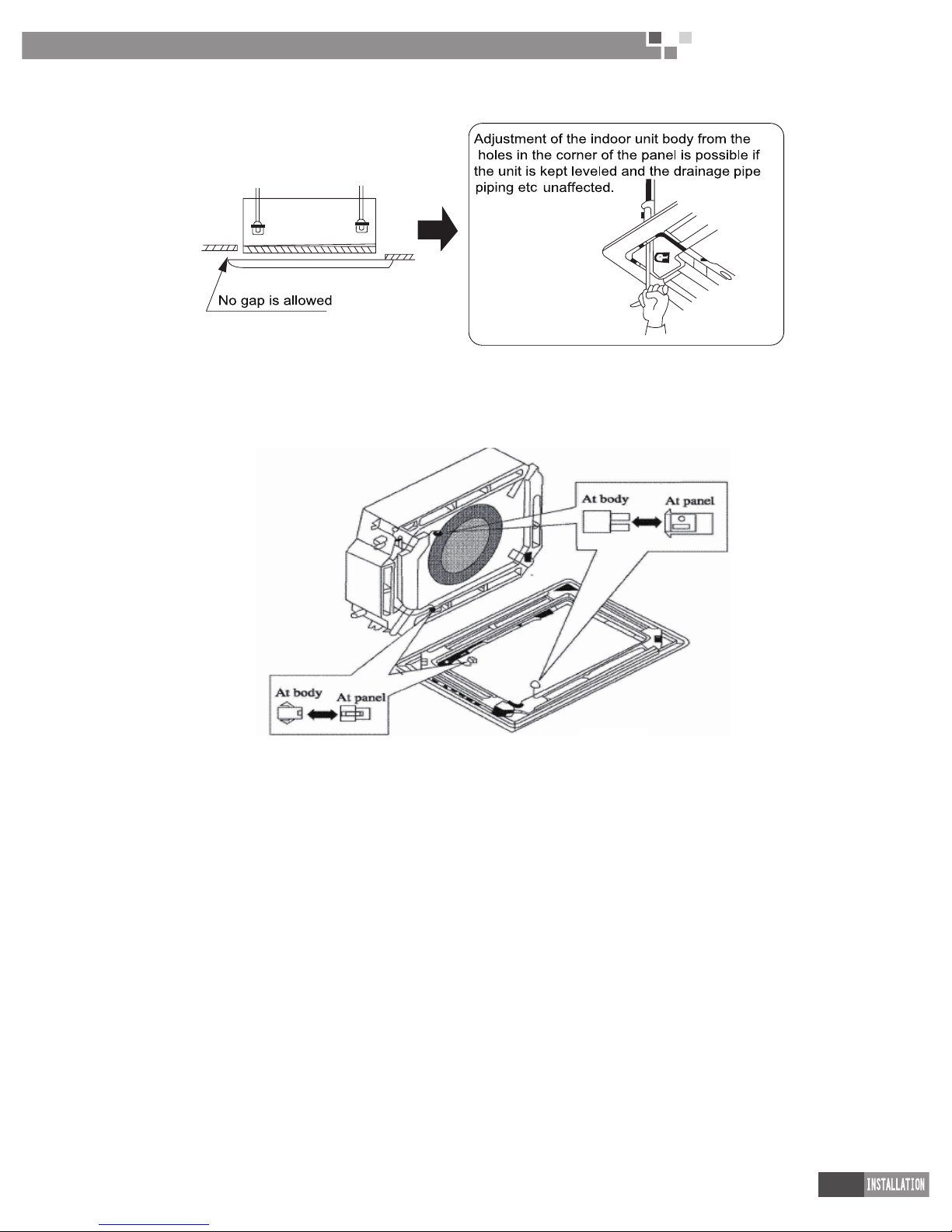
If gap is still left between the ceiling and the panel after screwing the screws, readjust the height of the unit
body.
5.2 After xing be sure no gap left between the ceiling and the panel
Wiring of the decoration panel.
Connect the joints for swing ap motor lead wire (at 2 places) installed on the panel.
Page 38

36
Cassette Type Fan Coil
Unit Service Manual
MAINTENANCE
Page 39

37
Cassette Type Fan Coil
Unit Service Manual
MAINTENANCE
1.TROUBLESHOOTING
Panel TB03 displaying the error code :
Error code Error
E0 Water pump error
E6 Communications error
F0 temperature sensor error at the return air inlet
F1 Evaporator temp. sensor error
F5 temperature sensor error at the wire controller
E9 Full water protection
FE Entering cooling temp. sensor error of the evaporator
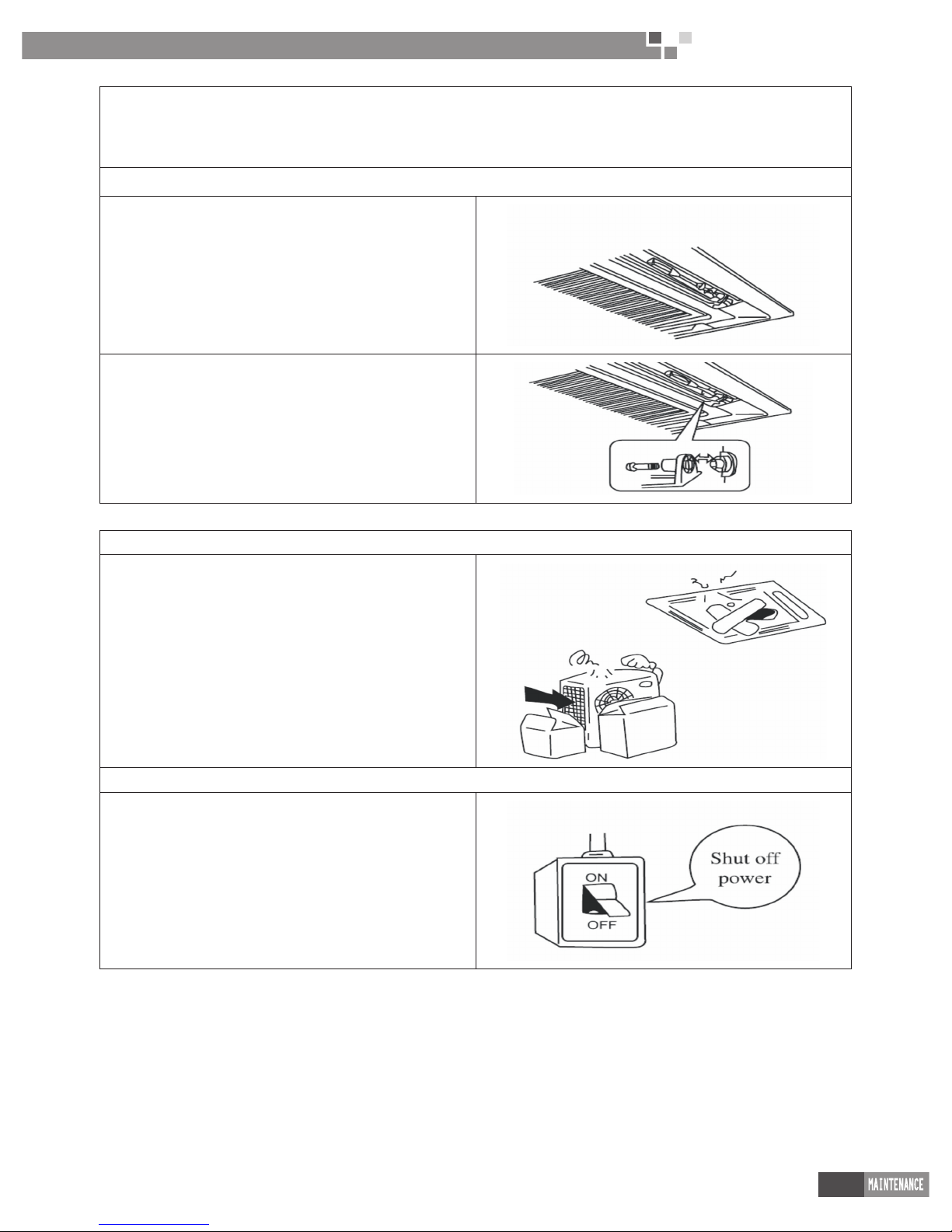
2.CARE AND MAINTENANCE
Please pull out the power plug after you used the air condition.
Warning:
1. Pull out the power plug before cleaning.
2. Do not splash water directly.
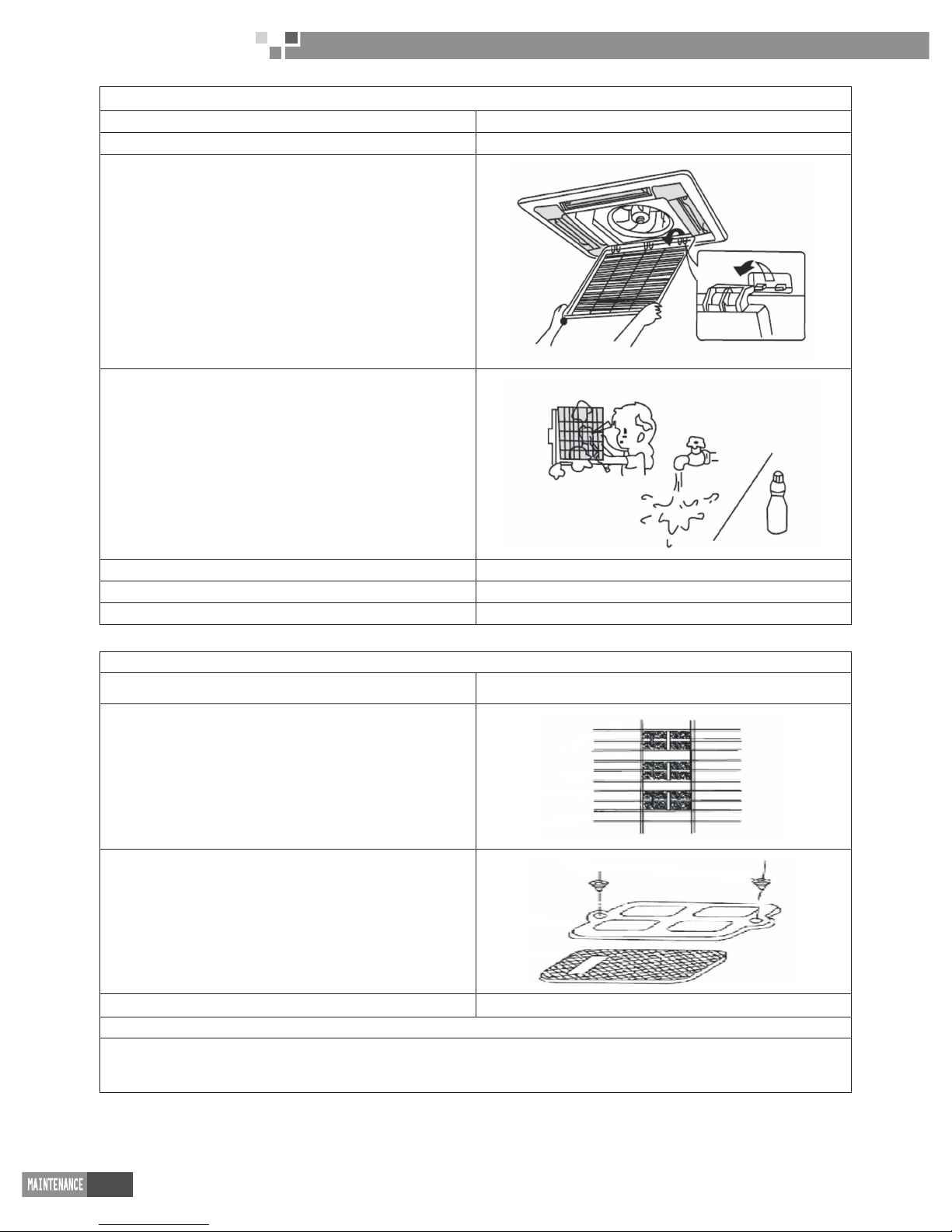
How to clean the air lter
1. Open the suction grille.
2. Slide both knobs simultaneously as shown and then pull them downward slowly.
buckle
1. Remove the air lters.
2. Slide knobs on the back of the suction grille out ward and remove the air lter.
3. Then remove three air cleaners on it.
●Clean the lter
Use vacuum or wash the air lter with water when the air lter is very dirty, use neutral
detergent and water. Let the lter dry naturally at shady place.
Note:
1. Do not clean with hot water.
2. Do not dry over re.
3. Do not run the air condition without the air lter.
4. The suction grille must be opened by skilled personnel.
●Fix the air lters
1. Fix three air-cleaner on the air lter and then x the air lter to the suction grille by
hanging it to the projected portion above suction grille.
2. Set air lter by sliding the knob on the back of the suction grille inward.
Shut the suction grille. Refer to step.1
Page 40
38
Cassette Type Fan Coil
Unit Service Manual
How to clean to the suction grille
1. Open the suction grille See step 1 of “How to clean the air lter”.
2. Remove the air lters See step 2 of “How to clean the air lter”.
3. Remove the suction grille
Open the suction grille at 45°and then lift.
4. Wash with water.
When the suction grille is very dirty, use soft brush and neutral
detergent. Shake water and dry in a shady place.
5. Fix the suction grille. Refer to step 3.
6. Fix air lter. See step 4 of “How to clean the air lter”.
7. Close the suction grille. Refer to step 1.
Changing air cleaner
1. Open the suction grille See step 1 of “How to clean the air lter”
2.Remove the air cleaner
Remove the air lter and remove the air cleaner after unscrewing.
3. Take off packing bag and put in new static electricity ber lter,
then x them on the air lter.
4. Fix the air lter See step 4 of “How to clean the air lter”
Air cleaner functions and service cycle time.
Absorbs bad smell in air such as carbon monoxide carbon dioxide, benzyl, gasoline and so on.
Absorbs harmful objects bigger than 1.0 um in air such as dust, germ, virus and so on.
It can be used for about half a year to one year.
Page 41
39
Cassette Type Fan Coil
Unit Service Manual
How to clean the air outer and case.
●Clean with soft cloth or use water and neutral detergent.
●Do not use gasoline, benzene, thinner, polishing powder, liquid insecticide, which may cause discoloring or warping.
●If the air ow ap is very dirty, you may remove it to clean as shown below.
Detach and x the ap.
1. Detach the ap
Loosen the screws on the sides of the ap clean with soft cloth.
2. Fix the ap
Set the ribs on the sides of the air outlet to the slit of the ap and
then screw together to x the ap.
Before starting the air conditioner for the rst time in the season.
1. Check to make sure no objects obstructing the intake and
outlets parts on both the indoor and outdoor units.
2. Check to make sure ground wire is connected and that is not
damaged.
3.Check to make sure air lter has been cleaned.
4. Turn on the power 6 hours before starting the air conditioner.
End of season cleaning
1. Clean the lter and the body of the unit.
2. Turn off power.
3. Clear outdoor of dust.
4. If there is any rust in the outdoor unit, this should be painted
over to prevent the rust from spreading.
Page 42

40
Cassette Type Fan Coil
Unit Service Manual
3. WIRING DIAGRAM
FP-8XD-E; FP-10XD–E; FP-12.5XD-E; FP-14XD-E;FP-14XD-E;FP-18XD-E.
POWER:
WATER
VALVE
COMMUNICATION CORD
Manual Panel
LIMIT
W6
W14
W13
SWITCH
HEAT
Temperature limiter
PUMP MOTOR
POWER TRANSFORMER
Attention:The Manal Panel
is the optional accessory
FANM OTOR
GN
ROOM TEMP
SENSOR
PIPE TEMP
SENSOR
LIQUID
SWITCH
Evaporator
FP-8XD/A-E; FP-10XD/A–E; FP-12.5XD/A-E; FP-14XD/A-E;FP-16XD/A-E; FP-18XD/A-E.
POWER:
VALVE
WATER
COMMUNICATION CORD
Manual Panel
PUMP
FAN MOTOR
MOTOR
POWERT RANSFORMER
SWING MOTOR
Attention:The Manual Panel
is the optional accessory
ROOM TEMP.
SENSOR
PIPE TEMP.
Evaporator
LIMIT
SWITCH
SENSOR
LIQUID
SWITCH
Page 43

41
Cassette Type Fan Coil
Unit Service Manual
Model: FP-51XD –E; FP-68XD –E.
POWER:
VALVE
WATER
Manual Panel
FANM OTOR
PUMP MOTOR POWERT RANSFORMER
SWING MOTOR
FUT
Attention:The Manual Panel
is the optional accessory
ROOM TEMP.
SENSOR
PIPE TEMP.
SENSOR
LIQUID
SWITCH
Model:FP-85XD/B-T;FP-102XD/B-T;FP-125XD/B-T;FP-140XD/B-T;FP-160XD/B-T;FP-180XD/B-T;FP200XD/B-T.
Page 44

42
Cassette Type Fan Coil
Unit Service Manual
Model:FP-68XDT/B-K; FP-85XDT/B-K; FP-125XDT/B-K; FP-180XDT/B-K.
4. DISASSEMBLY AND ASSEMBLY PROCEDURE OF MAIN PARTS
Model;FP-8XD-E; FP-10XD–E; FP-12.5XD-E; FP-14XD-E; FP-16XD-E; FP-18XD-E;P-8XD/A-E; FP-10XD/
A–E; FP-12.5XD/A-E; FP-14XD/A-E;FP-16XD/A-E; FP-18XD/A-E; FP-85XD/B-T; FP-102XD/B-T: FP-125XD/
B-T; FP-140XD/B-T; FP-160XD/B-T; FP-180XD/B-T; FP-200XD/B-T; FP-85XD/B-T; FP-102XD/B-T: FP-125XD/
B-T; FP-140XD/B-T; FP-160XD/B-T; FP-180XD/B-T; FP-200XD/B-T; FP-68XDT/B-K; FP-85XDT/B-K; FP125XDT/B-K; FP-180XDT/B-K.
Disassembly Procedures of Indoor Unit ( Panel T01)
Remark: Make sure that the unit is stopped running and power supply is cut off before removal of the motor.
Process Pictorial View Handling Description
1.Disassemble
the grille of the
front panel
Push the left and right buckles on the grille of the
front panel toward the center and meanwhile pull
it upward until it forms a 45℃angle, after that pull
the grille backward.
2. Disassemble
the front panel.
Cover
Screw
Six-Creo
Plug
Electric Box Cover I
Electric Box Cover II
Disconnect the power cord of the fan motor and
the plug of the limit switch.
Open the cover װ of the electric box and
disconnect the six-cord plug, then remove covers
on four corners away, after that, loosen the screws
to the right position and turn the front panel
counter clockwise and lastly pull it out upward.
Page 45

43
Cassette Type Fan Coil
Unit Service Manual
3. Disassemble
the drain pan.
Electrical Box Cover
Loosen the screws on the coverⅠ of the
electrical box and then open the cover.
4.Disassemble
the electrical box
Screw
Loosen two screws xing the electric box and then
disconnect each wiring terminals, after that take the
electric box out upward.
5.Disassemble the
ow-guide loop
Scre
w
Flow-Guide Loop
Loosen the screws fixing the flow-guide loop and
then turn it counter clockwise.
6.Disassemble
the drain pan
Screw
Loose the screws on the drain pan and take it out
upward.
7.Disassemble
the fan blade
Nut with W
asher
Fan Blade
Loosen the screws on the fan blade and then take it
out upward.
Page 46

44
Cassette Type Fan Coil
Unit Service Manual
8. Disassemble
the evaporator
Screw
Screw
Connection Board
Clamp
Fixed Mount
Mounting Plate
Baffle
S
crew
Evaporator
Loosen the screws on the mounting plate and
take it out.
Loosen the screws on the baffle of the pipe
outlet, and then press it downward to pull out the
buckles on both side, after that, take the baffle
away.
Loosen the screws and clamps on the connection
board of the evaporator, disconnect the earth
lead, and then take the power cord of the motor,
electric heater and earth lead out through the
wire-cross hole, after that loosen the screws on
the xed mount and remove it away, nally take
the evaporator out upward.
9. Disassemble
the motor
Screw
Motor
Retaining Plate
Loosen the screws on the retaining plate and
the screw bolts on the motor, after that, take the
motor out.
10. Disassemble
the water pump
and the drain pipe
Drain Pipe
Screw
Screw
Loosen four screws fixing the water pump,
disconnect the water pipe of the pump, take the
mounting bracket away, then loosen these two
screws xing the water pipe, after that, take the
water pipe away.
Page 47

45
Cassette Type Fan Coil
Unit Service Manual
Model: FP-51XD –E; FP-68XD –E.
Disassembly Procedures of Indoor Unit
Remark: Make sure that the unit is stopped running and power supply is cut off before removal of the motor.
Process Pictorial View Handling Description
1. Disassemble
the grille of the
front panel
Buckle
Buckle
Push the left and right buckles on the grille of the
front panel toward the center and meanwhile pull
it upward until it forms a 45℃angle, after that pull
the grille backward.
2.Disassemble
the front panel
Screw
Screw
Front panel
Disconnect the power cord of the fan motor and
the plug of the limit switch.
Open the cover
Ⅱ
of the electric box and
disconnect the six-cord plug, then remove covers
on four corners away, after that, loosen the screws
to the right position and turn the front panel
counter clockwise and lastly pull it out upward.
3. Disassemble
the drain pan
Drain Pan
Screw
Screw
Drain Pan
Loose the screws on the cover Ⅰof the electric
box and then take the cover away.
Page 48

46
Cassette Type Fan Coil
Unit Service Manual
4. Disassemble
the electrical box
Screw
Screw
Screw
Electrical Box Cover
Electrical Box Cov
Screw
Screw
Screw
Electrial Box Cover
Electrial Box
Loosen two screws on the cover of the electric box
and then remove it away.
Disconnect the wiring terminals of the motor and
the temperature sensing bulb, then loosen two
screws fixing the electric box, after that, remove
the electric box away.
5. Disassemble
the baffle at the
pipe outlet.
Baffle
Screw
Screw
Bafe
Loosen two screws on the bafe and take it out by
turning it upward.
6. Disassemble
the water pump
Water Pump
S
crew
Drain Pipe
Screw
Screw
Screw
Drain Pipe
Water Pump
Loosen the screws xing the drain pan and then
take the it out upward.
Page 49

47
Cassette Type Fan Coil
Unit Service Manual
7. Disassemble
the left fender
Left Fender
Screw
Screw
Left Fender
Loosen two screws on the left fender and then
take it out upward.
8.Disassemble
the fan blade
Screw
Fan Blade
Fan Blade
Screw
Loosen the screws on the fan
blade and then take it out.
9.Disassemble
the evaporator
Connection Board
Evaporator
Fixed Mount
Connection Board
Fixed Mount
Evaporator
Loosen the screws on the connection board and
the xed mount of the evaporator, and then remove
them away, after that, take the evaporator out.
10.Disassemble
the motor
Screw
Motor
Screw
Loosen four screws xing the motor
and take the motor out.
Page 50

48
Cassette Type Fan Coil
Unit Service Manual
5. EXPLODED VIEWS AND SPARE PART LISTS
Model: FP-8XD-E; FP-10XD–E; FP-12.5XD-E; FP-14XD-E;FP-16XD-E; FP-18XD-E exploded views and
spare parts list.
Page 51

49
Cassette Type Fan Coil
Unit Service Manual
NO.
Discription
FP-8XD-E FP-10XD-E FP-12.5XD-E
Quantity EM52000050 EM52000060 EM52000030
Name of Parts Part Code Part Code Part Code
1 Tube Exit plate 02217102 02217102 02217102 1
2 Body Fixing Plate 01332701 01332701 01332701 4
3 Front Side Plate 01302718 01302718 01302718 1
4 Left Side Plate 01302715 01302715 01302715 1
5 Base Plate 01222701 01222701 01222701 1
6 Rear Side Plate 01302714 01302714 01302714 1
7 Bottom Foam 52012722 52012722 52012722 1
8 Motor Gasket 76712711 76712711 76712711 4
9 Bolt M6 70212711 70212711 70212711 4
10 Motor Support 01702701 01702701 01702701 1
11 Motor 15012703 15012703 15012703 1
12 Electric Heater 32002701 32002701 32002701 1
13 Centrifugal Fan 10312705 10312705 10312705 1
14 Evaporator Linkage 01074042 01074042 01074042 1
15 Cable-cross Loop 76512701 76512701 76512701 1
16 Tube sensor 3900012125 3900012125 3900012125 1
17 sensor insert B 42020063 42020063 42020063 1
18 Heat exchanger 01127104 01127104 01127104 1
19 Water Tray Assy 20182701 20182701 20182701 1
20 Rubber Stem 76712701 76712701 76712701 1
21 Electric Base Plate 01412722 01412721 01412721 1
22 Flow-guide Loop 10372701 10372701 10372701 1
23 Electric Box 20102701 20102701 20102701 1
24 Wire Clamp 71010102 71010102 71010102 4
25 Terminal Board 42011142 42011142 42011142 1
26 relay 44010206 44010206 44010206 1
27 Transformer 43110170 43110170 43110170 1
28 Electric Box Cover I 20102702 20102702 20102702 1
29 Room sensor 39000110 39000110 39000110 1
30 Remote Controller 30512506 30512506 30512506 1
31 Electric Box Cover II 20102703 20102703 20102703 1
32 Main 30225904 30225904 30225904 1
33 Capacitor 33010026 33010010 33010010 1
34 Drainage Plastic 06122702 06122702 06122702 1
35 Evap Support 01072703 01072703 01072703 1
36 Nut with Washer M6 70310012 70310012 70310012 1
37 Fan Fixer 10312701 10312701 10312701 1
38 Water Pump 43130324 43130324 43130324 1
39 Pump Gasket 76712702 76712702 76712702 3
40 Pump Support 01332702 01332702 01332702 1
41 Water Level Switch 45010201 45010201 45010201 1
42 Pump Drainpipe 05230026 05230026 05230026 1
43 Right Side Plate 01302716 01302716 01302716 1
44 Cable-cross Block 76512702 76512702 76512702 1
45 Pump Cover Plate 01252713 01252713 01252713 1
46 Bolt 70212701 70212701 70212701 3
Above data is subject to change without notice,pls refer the SP in global service website.
Page 52

50
Cassette Type Fan Coil
Unit Service Manual
NO.
Discription
FP-14XD-E FP-16XD-E FP-18XD-E
Quantity EM52000070 EM52000080 EM52000040
Name of Parts Part Code Part Code Part Code
1 Tube-exit Plate 02217102 02217102 02217102 1
2 Body Fixing Plate 01332701 01332701 01332701 4
3 Front Side Plate 01302713 01302713 01302713 1
4 Left Side Plate 01302711 01302711 01302711 1
5 Base Plate 01222732 01222732 01222732 1
6 Rear Side Plate 01302709 01302709 01302709 1
7 Bottom Foam 52012721 52012721 52012721 1
8 Motor Gasket 76712711 76712711 76712711 4
9 Bolt 70210012 70210012 70210012 4
10 Motor Support 01702701 01702701 01702701 1
11 Motor FN50T 15012710 15012710 15012710 1
12 Electric Heater 32002701 32002701 32002701 1
13 Centrifugal Fan 10310101 10310101 10310101 1
14 Evap Connection 01072735 01072735 01072735 1
15 Cable-cross Loop 76515202 76515202 76515202 1
16 Tube sensor 3900012125 3900012125 3900012125 1
17 sensor insert B 42020063 42020063 42020063 1
18 Heat exchanger 01187104 01187104 01187104 1
19 Water Tray 20182701 20182701 20182701 1
20 Screw 70140032 70140032 70140032 4
21 Electric Plate 01412721 01412721 01412721 1
22 Flow-guide Loop 10372722 10372722 10372722 1
23 Electric Box 20102701 20102701 20102701 1
24 Wire Clamp 71010103 71010103 71010103 3
25 Terminal Board 42011142 42011142 42011142 1
26 relay 44010206 44010206 44010206 1
27 Transformer 43110170 43110170 43110170 1
28 Electric Box Cover I 20102702 20102702 20102702 1
29 Room sensor 39000110 39000110 39000110 1
30 Remote Controller 30505004 30505004 30505004 1
31 Electric Box Cover II 20102703 20102703 20102703 1
32 Main 30225904 30225904 30225904 1
33 Capacitor 33010010 33010013 33010012 1
34 Drainage Plastic 06122702 06122702 06122702 1
35 Evap Support 01072705 01072705 01072705 2
36 Nut with Washer 70310012 70310012 70310012 1
37 Fixer 10312701 10312701 10312701 1
38 Water Pump 43130324 43130324 43130324 1
39 Pump Gasket 76712702 76712702 76712702 3
40 Pump Support 01332721 01332721 01332721 1
41 Water Level Switch 45010201 45010201 45010201 1
42 Pump Drainpipe 05230026 05230026 05230026 1
43 Right Side Plate 01302712 01302712 01302712 1
44 Cable-cross Block 76512702 76512702 76512702 1
45 Pump Cover Board 01252713 01252713 01252713 1
46 Bolt 70212701 70212701 70212701 3
Above data is subject to change without notice,pls refer the SP in global service website.
Page 53

51
Cassette Type Fan Coil
Unit Service Manual
P-8XD/A-E; FP-10XD/A–E; FP-12.5XD/A-E; FP-14XD/A-E;FP-16XD/A-E; FP-18XD/A-E exploded views
and spare parts list.
Page 54

52
Cassette Type Fan Coil
Unit Service Manual
NO.
Discription
FP-8XD/A-E FP-10XD/A-E FP-12.5XD/A-E
Quantity EM52000450 EM52000460 EM52000470
Name of Parts Part Code Part Code Part Code
1 Tube Exit plate 02217102 02217102 02217102 1
2 Body Fixing Plate 01332701 01332701 01332701 4
3 Front Side Plate 01302718 01302718 01302718 1
4 Left Side Plate 01302715 01302715 01302715 1
5 Base Plate 01222701 01222701 01222701 1
6 Rear Side Plate 01302714 01302714 01302714 1
7 Bottom Foam 52012722 52012722 52012722 1
8 Motor Gasket 76712711 76712711 76712711 4
9 Bolt M6 70212711 70210051 70210051 4
10 Motor Support 01702701 01702701 01702701 1
11 Motor FN35B 15012703 15012703 15012703 1
12 Centifugal Fan 10312705 10312705 10312705 1
13 Evaporator Linkage 01074042 01072710 01072710 1
14 Cable-cross Loop 76515202 76513101 76513101 1
15 Tube sensor 3900012125 3900012125G 3900012125G 1
16 sensor insert B 42020063 42020063 42020063 1
17 Heat exchanger 01127104 01127104 01127104 1
18 Water Tray Assy 20182701 20182701 20182701 1
19 Rubber Stem 76712701 70140032 70140032 1
20 Electric Base Plate 01412721 01412721 01412721 1
21 Flow-guide Loop 10372701 10372701 10372701 1
22 Electric Box 20102701 20102701 20102701 1
23 Wire Clamp 71010102 71010102 71010102 4
24 Terminal Board 42011142 42011142 42011142 1
25 Transformer 43110233 43110233 43110233 1
26 Electric Box Cover I 20102702 20102702 20102702 1
27 Room sensor 39000111 390001911 390001911 1
28 Remote Controller 305125063 305125063 305125063 1
29 Electric Box Cover II 20102703 20102703 20102703 1
30 Main PCB 30225904 30225904 30225904 1
31 Capacitor 33010026 33010010 33010010 1
32 Drainage pipe 4367120 05230026 05230026 1
33 Evap Support 01072703 01074042 01074042 1
34 Nut with Washer 70310012 70310012 70310012 1
35 Fan Fixer 10312701 10312701 10312701 1
36 Water Pump 43130324 43130324 43130324 1
37 Pump Gasket 76712702 76712702 76712702 3
38 Pump Support 1329416 01332702 01332702 1
39 Water Level Switch 45010201 45010201 45010201 1
40 Pump Drainpipe 05230026 05230026 05230026 1
41 Right Side Plate 01302716 01302716 01302716 1
42 Cable-cross Block 76512702 76512702 76512702 1
43 Pump Cover Plate 01252713 01252713 01252713 1
44 Bolt 70212701 70212711 70212711 3
Above data is subject to change without notice,pls refer the SP in global service website.
Page 55
53
Cassette Type Fan Coil
Unit Service Manual
NO.
Discription
FP-14XD/A-E FP-16XD/A-E FP-18XD/A-E
Quantity EM52000480 EM52000490 EM5200500
Name of Parts Part Code Part Code Part Code
1 Tube-exit Plate 02217102 02217102 02217102 1
2 Body Fixing Plate 01332701 01332701 01332701 4
3 Front Side Plate 01302713 01302718 01302718 1
4 Left Side Plate 01302711 01302715 01302715 1
5 Base Plate 01222701 01222701 01222701 1
6 Rear Side Plate 01302709 01302714 01302714 1
7 Bottom Foam 52012721 52012722 52012722 1
8 Motor Gasket 76712711 76712711 76712711 4
9 Bolt 70210051 70210051 70210051 4
10 Motor Support 01702701 01702701 01702701 1
11 Motor 15012710 15012703 15012703 1
12 Centifugal Fan 10310101 10312705 10312705 1
13 Evap Connection 01072710 01072710 01072710 1
14 Cable-cross Loop 76513101 76513101 76513101 1
15 Tube sensor 3900012125G 3900012125G 3900012125G 1
16 sensor insert B 42020063 42020063 42020063 1
17 Heat exchanger 01127102 01127104 01127104 1
18 Water Tray 20182701 20182701 20182701 1
19 Screw 70140032 70140032 70140032 4
20 Electric Plate 01412721 01412721 01412721 1
21 Flow-guide Loop 10372722 10372701 10372701 1
22 Electric Box 20102701 20102701 20102701 1
23 Wire Clamp 71010102 71010102 71010102 3
24 Terminal Board 42011142 42011142 42011142 1
25 Transformer 43110233 43110233 43110233 1
26 Electric Box Cover I 20102702 20102702 20102702 1
27 Room sensor 390001911 390001911 390001911 1
28 Remote Controller 305125063 305125063 305125063 1
29 Electric Box Cover II 20102703 20102703 20102703 1
30 Main PCB 30225904 30225904 30225904 1
31 Capacitor 33010026 33010012 33010012 1
32 Drainage Plastic 05230026 05230026 05230026 1
33 Evap Support 01072732 01074042 01074042 2
34 Nut with Washer 70310012 70310012 70310012 1
35 Fixer 10312701 10312701 10312701 1
36 Water Pump 43130324 43130324 43130324 1
37 Pump Gasket 76712702 76712702 76712702 3
38 Pump Support 01332721 01332702 01332702 1
39 Water Level Switch 45010201 45010201 45010201 1
40 Pump Drainpipe 05230026 05230026 05230026 1
41 Right Side Plate 01302712 01302716 01302716 1
42 Cable-cross Block 76512702 76512702 76512702 1
43 Pump Cover Board 01252713 01252713 01252713 1
44 Bolt 70212711 70212711 70212711 3
Above data is subject to change without notice,pls refer the SP in global service website.
Page 56
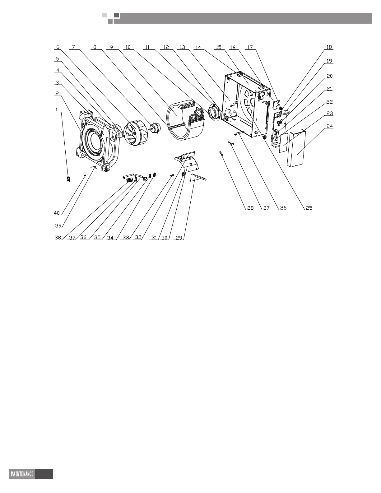
54
Cassette Type Fan Coil
Unit Service Manual
FP-51XD –E; FP-68XD –E exploded views and spare parts list.
Page 57

55
Cassette Type Fan Coil
Unit Service Manual
NO.
Discription
FP-51XD –E FP-68XD –E
Quantity EM52000010 EM52000020
Name of Parts Part Code Part Code
1 Remote Controller 30512506 30512506 1
2 Water Tray 20182703 20182703 1
3 Water Tray Foam for Fresh Air In taking 12312702 12312702 1
4 Water Tray Foam 12312703 12312703 1
5 Fan Fixer 76712709 76712709 1
6 Centrifugal Fan 10312702 10312702 1
7 Motor 15012707 15012707 1
8 Evap Support 01072714 01072714 1
9 Surface Air Cooler Assy 01109501 01109501 1
10 Motor Support 01702702 01702702 1
11 Motor Gasket 76712705 76712705 4
12 Water Tray support 01332706 01332706 4
13 Front Side Plate 01302741 01302741 2
14 Body Fixer 01332705 01332705 4
15 Right Side Plate 01302743 01302743 2
16 Tube-exit plate 01382719 01382719 1
17 Cable-cross Loop 76512701 76512701 2
18 Wire Clamp 71010102 71010102 2
19 Electric Box Assy 01402705 01402705 1
20 Terminal Board(5bit) 42011142 42011142 1
21 Transformer 43110233 43110233 1
22 Capacitor 33010035 33010035 1
23 Main PCB 30225903 30225903 1
24 Electric Box Cover 01412723 01412723 1
25 Base Plate 01222712 01222712 1
26 Cord Bafe Plate 01362701 01362701 1
27 Connecting Wire 40030079 40030079 1
28 Power Cord Assy 40020203 40020203 1
29 Left Bafe Plate 01362703 01362703 1
30 Evap Connection 01072713 01072713 1
31 Water Level Switch Support 24212705 24212705 1
32 Right Bafe Plate 01362702 01362702 1
33 Water Level Switch 450127011 450127011 1
34 Pump Gasket 1 76712707 76712707 1
35 Pump Gasket 2 76712708 76712708 1
36 Pump Drainage 05232722 05232722 1
37 Pump Support 01332707 01332707 1
38 Water Pump 43130320 43130320 1
39 Room Sensor 39000191 39000191 1
40 Wire Clamp 71010105 71010105 1
Above data is subject to change without notice,pls refer the SP in global service website.
Page 58
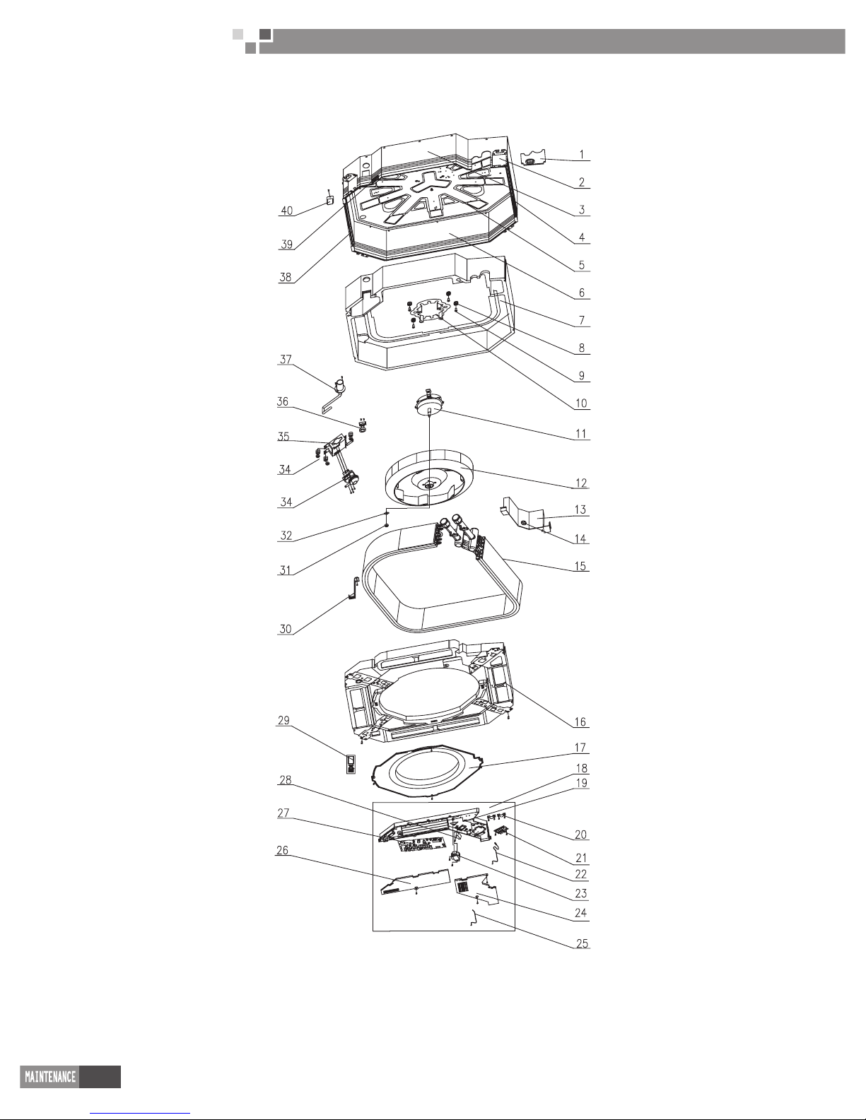
56
Cassette Type Fan Coil
Unit Service Manual
FP-85XD/B-T; FP-102XD/B-T;FP-125XD/B-T;FP-140XD/B-T;FP-160XD/B-T;FP-180XD/B-T;FP-200XD/B-T
exploded views and spare parts list.
Page 59

57
Cassette Type Fan Coil
Unit Service Manual
NO.
Discription
FP-85XD/B-T FP-102XD/B-T
Quantity EM520N0930/EM520N0940 EM520N0910/EM520N0920
Name of Parts Part Code Part Code
1 Tube-exit Plate /
2 Body Fixing Plate 01332701 01332701 4
3 Front Side Plate 01302717 01302717 1
4 Left Side Plate 01302740 01302740 1
5 Base Plate 01222701 01222701 1
6 Rear Side Plate 01302719 01302719 1
7 Bottom Foam 52012720 52012720 1
8 Motor Gasket 76712711 76712711 4
9 Bolt 70210051 70210051 4
10 Motor Support 01702701 01702701 1
11 Motor 15704901 15704901 1
12 Centifugal Fan 10312721 10312721 1
13 Evap Connection 01072004 01072004 1
14 Cable-cross Loop 76515202 76515202 1
15 Heat exchanger 01126000042 01126000042 1
16 Water Tray 20182701 20182701 1
17 Flow-guide Loop 10372722 10372722 1
18 Electric Box asm 01396000021 01396000025 1
19 Electric Box 26909439 26909439 1
20 Wire Clamp 71010102 71010102 2
21 Terminal Board 42011221 42011221 1
22 Tube sensor 390001982G 390001982G 1
23 Transformer 4311022602 4311022602 1
24 Electric Box Cover I 20102702 20102702 1
25 Room sensor 390001912 390001912 1
26 Electric Box Cover II 20102703 20102703 1
27 Main PCB 30226275 30226275 1
28 Capacitor 3301074702 3301074711 1
29 Remote Controller 30510516 30510516 1
30 Evap Support 01072003 01072003 2
31 Nut with Washer 70310012 70310012 3
32 Fixer 10312701 10312701 1
33 Water Pump 43130324 43130324 1
34 Pump Gasket 76712702 76712702 3
35 Pump Support 01332001 01332001 1
36 Water Level Switch 45018012 45018012 1
37 Pump Drainpipe 05232721 05232721 1
38 Right Side Plate 01302710 01302710 1
39 Cable-cross Block 76512702 76512702 1
40 Pump Cover Board 01252712 01252712 1
Above data is subject to change without notice,pls refer the SP in global service website.
Page 60

58
Cassette Type Fan Coil
Unit Service Manual
NO.
Discription
FP-125XD/B-T FP-140XD/B-T FP-160XD/B-T
Quantity EM520N0890/EM520N0900 EM520N0870EM520N0880 EM520N0850/EM520N0860
Name of Parts Part Code Part Code Part Code
1 Tube-exit Plate 02206000001 02206000001 02206000001 1
2 Body Fixing Plate 01332701 01332701 01332701 4
3 Front Side Plate 01302718 01302718 01302718 1
4 Left Side Plate 01302715 01302715 01302715 1
5 Base Plate 52012722 52012722 52012722 1
6 Rear Side Plate 01302714 01302714 01302714 1
7 Bottom Foam 52012722 52012722 52012722 1
8 Motor Gasket 76712711 76712711 76712711 4
9
Bolt 70210051 70210051 70210051 4
10 Motor Support 01702701 01702701 01702701 1
11 Motor 15704102 1570410202 1570410202 1
12 Centifugal Fan 10312705 10312705 10312705 1
13 Evap Connection 01072710 01072710 01072710 1
14 Cable-cross Loop 76515202 76515202 76515202 1
15 Heat exchanger 01126000030 01126000030 01126000044 1
16 Water Tray 20182701 20182701 20182701 1
17 Flow-guide Loop 10372722 10372722 10372722 1
18 Electric Box asm 01396000019 01396000030 01396000025 1
19 Electric Box 26909439 26909439 26909439 1
20 Wire Clamp 71010102 71010102 71010102 2
21 Terminal Board 42011221 42011221 42011221 1
22 Tube sensor 390001982G 390001982G 390001982G 1
23 Transformer 4311022602 4311022602 4311022602 1
24 Electric Box Cover I 20102702 20102702 20102702 1
25 Room sensor 390001912 390001912 390001912 1
26 Electric Box Cover II 20102703 20102703 20102703 1
27 Main PCB 30226275 30226275 30226275 1
28 Capacitor 3301074702 33010011 3301074711 1
29 Remote Controller 30510516 30510516 30510516 1
30 Evap Support 01072715 01072715 01072715 2
31 Nut with Washer 70310012 70310012 70310012 1
32 Fixer 10312701 10312701 10312701 1
33 Water Pump 43130324 43130324 43130324 1
34 Pump Gasket 76712702 76712702 76712702 3
35 Pump Support 01329416 01329416 01329416 1
36 Water Level Switch 45018012 45018012 45018012 1
37 Pump Drainpipe 05230026 05230026 05230026 1
38 Right Side Plate 01302716 01302716 01302716 1
39 Cable-cross Block 76512702 76512702 76512702 1
40 Pump Cover Board 01252713 01252713 01252713 1
Above data is subject to change without notice,pls refer the SP in global service website.
Page 61
59
Cassette Type Fan Coil
Unit Service Manual
NO.
Discription
FP-160XD/B-T FP-200XD/B-T
Quantity EM520N0830/EM520N0840 EM520N0810/EM520N0820
Name of Parts Part Code Part Code
1 Tube-exit Plate 02206000001 02206000001 1
2 Body Fixing Plate 01332701 01332701 4
3 Front Side Plate 01302713 01302713 1
4 Left Side Plate 01302711 01302711 1
5 Base Plate 01222701 01222701 1
6 Rear Side Plate 01302709 01302709 1
7 Bottom Foam 52012721 52012721 1
8 Motor Gasket 76712711 76712711 4
9 Bolt 70210051 70210051 4
10 Motor Support 01702701 01702701 1
11 Motor 1570490301 1570490301 1
12 Centifugal Fan 26904115 26904115 1
13 Evap Connection 01072733 01072733 1
14 Cable-cross Loop 76515202 76515202 1
15 Heat exchanger 01126000043 01126000043 1
16 Water Tray 20182701 20182701 1
17 Flow-guide Loop 10372722 10372722 1
18 Electric Box asm 01396000019 01396000025 1
19 Electric Box 26909439 26909439 1
20 Wire Clamp 71010102 71010102 2
21 Terminal Board 42011221 42011221 1
22 Tube Sensor 390001982G 390001982G 1
23 Transformer 4311022602 4311022602 1
24 Electric Box Cover I 20102702 20102702 1
25 Room sensor 390001912 390001912 1
26 Electric Box Cover II 20102703 20102703 1
27 Main PCB 30226275 30226275 1
28 Capacitor 3301074711 3301074711 1
29 Remote Controller 30510516 30510516 1
30 Evap Support 01072708 01072708 2
31 Nut with Washer 70310012 70310012 1
32 Fixer 10312701 10312701 1
33 Water Pump 43130324 43130324 1
34 Pump Gasket 76712702 76712702 3
35 Pump Support 01332721 01332721 1
36 Water Level Switch 45018012 45018012 1
37 Pump Drainpipe 05230026 05230026 1
38 Right Side Plate 01302712 01302712 1
39 Cable-cross Block 76512702 76512702 1
40 Pump Cover Board 01252713 01252713 1
Above data is subject to change without notice,pls refer the SP in global service website.
Page 62
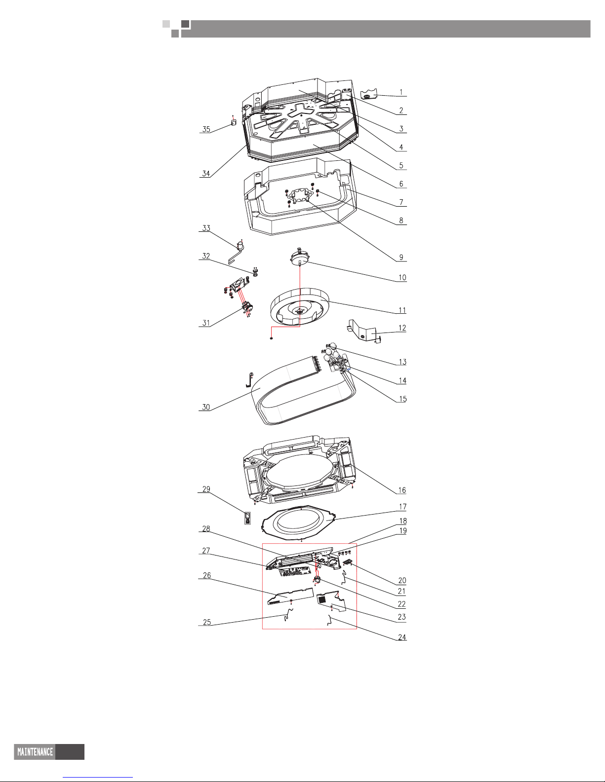
60
Cassette Type Fan Coil
Unit Service Manual
FP-68XDT/B-K exploded views and spare parts list.
Page 63

61
Cassette Type Fan Coil
Unit Service Manual
NO.
Discription
FP-68XDT/B-K
Quantity EM520N0990
Name of Parts Part Code
1 Tube Exit Plate Assy 01346000095 1
2 Body Fixing Plate 01332701 4
3 Front Side Plate 01302717 1
4 Left Side Plate 01302740 1
5 Base Plate 01222701 1
6 Rear Side Plate 01302719 1
7 Bottom Foam 52012720 1
8 Motor Gasket 76712711 4
9 Motor Support 01702701 1
10 Motor 15704901 1
11 Centifugal Fan 10312721 1
12 Evap Connection 01072004 1
13 Deation Valve 07108206 2
14 Valve chest (air release valve) 07336000028 2
15 Valve chest (air release valve) 0733600001501 2
16 Water Tray 20182701 1
17 Flow-guide Loop 0372701 1
18 Electric Box asm 1396000868 1
19 Electric Box 26909439 1
20 Terminal Board 42011221 1
21 Tube sensor 390001982G 1
22 Transformer 4311022602 1
23 Electric Box Cover I 20102702 1
24 Room sensor 390001912 1
25 Tube sensor 3900028807 1
26 Electric Box Cover II 20102703 1
27 Main PCB 30226275 1
28 Capacitor 3301074711 1
29 Remote Controller 30510516 1
30 Heat exchanger 01126000562 1
31 Water Pump 43130324 1
32 Water Level Switch 45018012 1
33 Pump Drainpipe 05232721 1
34 Right Side Plate 01302710 1
35 Pump Cover Board 01252712 1
Above data is subject to change without notice,pls refer the SP in global service website.
Page 64

62
Cassette Type Fan Coil
Unit Service Manual
FP-85XDT/B-K exploded views and spare parts list.
Page 65

63
Cassette Type Fan Coil
Unit Service Manual
NO.
Discription
FP-85XDT/B-K
Quantity EM520N0960
Name of Parts Part Code
1 Tube Exit Plate Assy 01346000095 1
2 Body Fixing Plate 01332701 4
3 Front Side Plate 01302717 1
4 Left Side Plate 01302740 1
5 Base Plate 01222701 1
6 Rear Side Plate 01302719 1
7 Bottom Foam 52012720 1
8 Motor Gasket 76712711 4
9 Motor Support 01702701 1
10 Motor 15704901 1
11 Centifugal Fan 10312721 1
12 Evap Connection 01072004 1
13 Deation Valve 07108206 2
14 Valve chest (air release valve) 07336000028 2
15 Valve chest (air release valve) 0733600001501 2
16 Water Tray 20182701 1
17 Flow-guide Loop 0372701 1
18 Electric Box asm 1396000868 1
19 Electric Box 26909439 1
20 Terminal Board 42011221 1
21 Tube sensor 390001982G 1
22 Transformer 4311022602 1
23 Electric Box Cover I 20102702 1
24 Room sensor 390001912 1
25 Tube sensor 3900028807 1
26 Electric Box Cover II 20102703 1
27 Main PCB 30226275 1
28 Capacitor 3301074711 1
29 Remote Controller 30510516 1
30 Heat exchanger 01126000562 1
31 Water Pump 43130324 1
32 Water Level Switch 45018012 1
33 Pump Drainpipe 05232721 1
34 Right Side Plate 01302710 1
35 Pump Cover Board 01252712 1
Above data is subject to change without notice,pls refer the SP in global service website.
Page 66

64
Cassette Type Fan Coil
Unit Service Manual
FP-125XDT/B-K exploded views and spare parts list.
Page 67

65
Cassette Type Fan Coil
Unit Service Manual
NO.
Discription
FP-125XDT/B-K
Quantity EM520N0970
Name of Parts Part Code
1 Tube Exit Plate Assy 01346000094 1
2 Body Fixing Plate 01332701 4
3 Front Side Plate 01302718 1
4 Left Side Plate 01302715 1
5 Base Plate 01222701 1
6 Rear Side Plate 01302714 1
7 Bottom Foam 52012722 1
8 Motor Gasket 76712711 4
9 Motor Support 01702701 1
10 Motor 15704102 1
11 Centifugal Fan 10312705 1
12 Evap Connection 01072710 1
13 Deation Valve 07108206 2
14 Valve chest (air release valve) 07336000028 2
15 Valve chest (air release valve) 0733600001501 2
16 Water Tray 20182701 1
17 Flow-guide Loop 10372722 1
18 Electric Box asm 01396000870 1
19 Electric Box 26909439 1
20 Terminal Board 42011221 1
21 Tube sensor 390001982G 1
22 Transformer 4311022602 1
23 Electric Box Cover I 20102702 1
24 Room sensor 390001912 1
25 Tube sensor 3900028807 1
26 Electric Box Cover II 20102703 1
27 Main PCB 30226275 1
28 Capacitor 3301074711 1
29 Remote Controller 30510516 1
30 Heat exchanger 01126000560 1
31 Water Pump 43130324 1
32 Water Level Switch 45018012 1
33 Pump Drainpipe 05230026 1
34 Right Side Plate 01302716 1
35 Pump Cover Board 01252713 1
Above data is subject to change without notice,pls refer the SP in global service website.
Page 68
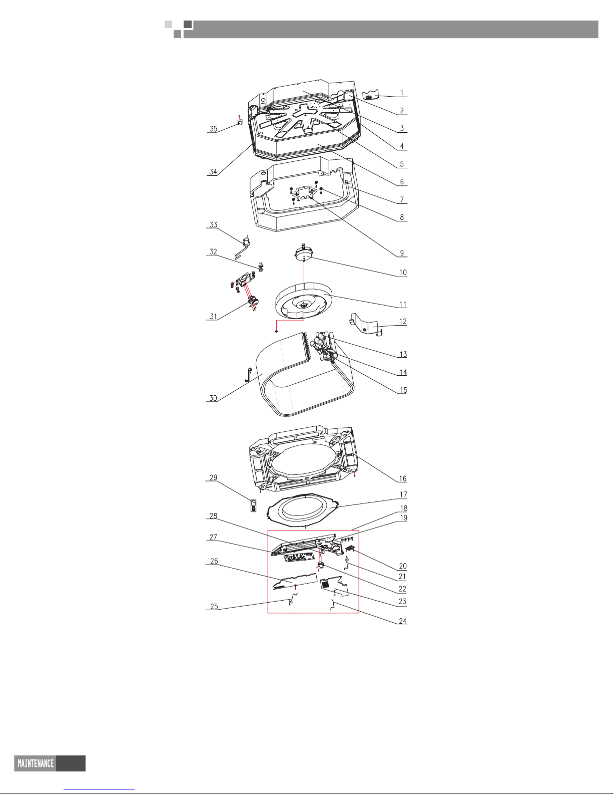
66
Cassette Type Fan Coil
Unit Service Manual
FP-180XDT/B-K exploded views and spare parts list.
Page 69

67
Cassette Type Fan Coil
Unit Service Manual
NO.
Discription
FP-180XDT/B-K
Quantity EM520N0980
Name of Parts Part Code
1 Tube Exit Plate Assy 01346000094 1
2 Body Fixing Plate 01332701 4
3 Front Side Plate 01302713 1
4 Left Side Plate 01302711 1
5 Base Plate 01222701 1
6 Rear Side Plate 01302709 1
7 Bottom Foam 52012721 1
8 Motor Gasket 76712711 4
9 Motor Support 01702701 1
10 Motor 15704903 1
11 Centifugal Fan 26904115 1
12 Evap Connection 01072733 1
13 Deation Valve 07108206 2
14 Valve chest (air release valve) 07336000028 2
15 Valve chest (air release valve) 0733600001501 2
16 Water Tray 20182701 1
17 Flow-guide Loop 10372722 1
18 Electric Box asm 01396000870 1
19 Electric Box 26909439 1
20 Terminal Board 42011221 1
21 Tube sensor 390001982G 1
22 Transformer 4311022602 1
23 Electric Box Cover I 20102702 1
24 Room sensor 390001912 1
25 Tube sensor 3900028807 1
26 Electric Box Cover II 20102703 1
27 Main PCB 30226275 1
28 Capacitor 3301074711 1
29 Remote Controller 30510516 1
30 Heat exchanger 01126000560 1
31 Water Pump 43130324 1
32 Water Level Switch 45018012 1
33 Pump Drainpipe 05230026 1
34 Right Side Plate 01302712 1
35 Pump Cover Board 01252713 1
Above data is subject to change without notice,pls refer the SP in global service website.
Page 70

JF00300710
 Loading...