

Gree FP-136WA/G-K, FP-170WA/G-K, FP-204WA/G-K, FP-34WAH/G-K, FP-51WAH/G-K Service Manual
...
Concealed Ceiling Type FCU

Contents
Engineering Data ........................................................................................................................................ 1
1. Product Introduction ............................................................................................................................... 2
1.1 Product Lineup .............................................................................................................................. 2
1.2 Nomenclature .............................................................................................................................. 10
1.3 Product Features......................................................................................................................... 11
1.3.1 Features ............................................................................................................................ 11
1.4 Working Principle ........................................................................................................................ 12
1.5 Technical Data ............................................................................................................................ 13
1.5.1 Data at Nominal Conditions .............................................................................................. 13
1.5.2 Temperature at Nominal Conditions ................................................................................. 26
1.5.3 Operation Range .............................................................................................................. 26
1.5.4 Electric Data ..................................................................................................................... 27
1.5.5 Capacity Correction .......................................................................................................... 27
2. Dimensions of the Unit ......................................................................................................................... 28
3. Explosive Views and Part Lists ............................................................................................................ 29
4. Scope of Supply ................................................................................................................................... 54
Design & Selection ................................................................................................................................... 55
1. Selection Principle ................................................................................................................................ 56
1.1 Selection Steps ........................................................................................................................... 56
1.2 Allowable Noise Level for Buildings ............................................................................................ 56
1.3 Example for Selection ................................................................................................................. 56
Unit Control ............................................................................................................................................... 59
1. Control logic.......................................................................................................................................... 60
2. AC connected with PC (long distance monitoring) .............................................................................. 60
3. AC control principle sketch ................................................................................................................... 60
Unit Installation ......................................................................................................................................... 61
1. Preparation before Installation ............................................................................................................. 62
1.1 Tools ............................................................................................................................................ 62
1.2 Materials ...................................................................................................................................... 64
1.3 Drain Hose .................................................................................................................................. 65
1.4 Insulation ..................................................................................................................................... 66
2. Installation ............................................................................................................................................ 67
2.1 Precautions for Installation.......................................................................................................... 67
2.2 Installation Steps ......................................................................................................................... 70
Test Operation & Troubleshooting & Maintenance .................................................................................. 71
1. Error List ............................................................................................................................................... 72
2. Electric Diagrams ................................................................................................................................. 73
3. Replacement of Key Parts ................................................................................................................... 73
3.1 Replacement of the Motor........................................................................................................... 73
3.2 Replacement of the Cooler ......................................................................................................... 75

Enginnering Data
Engineering Data
1
Enginnering Data
Series
Model
Product Code
Cooling
Capacity
(kW/Ton)
Heating
Capacity
(kW/Ton)
Power Supply
Picture
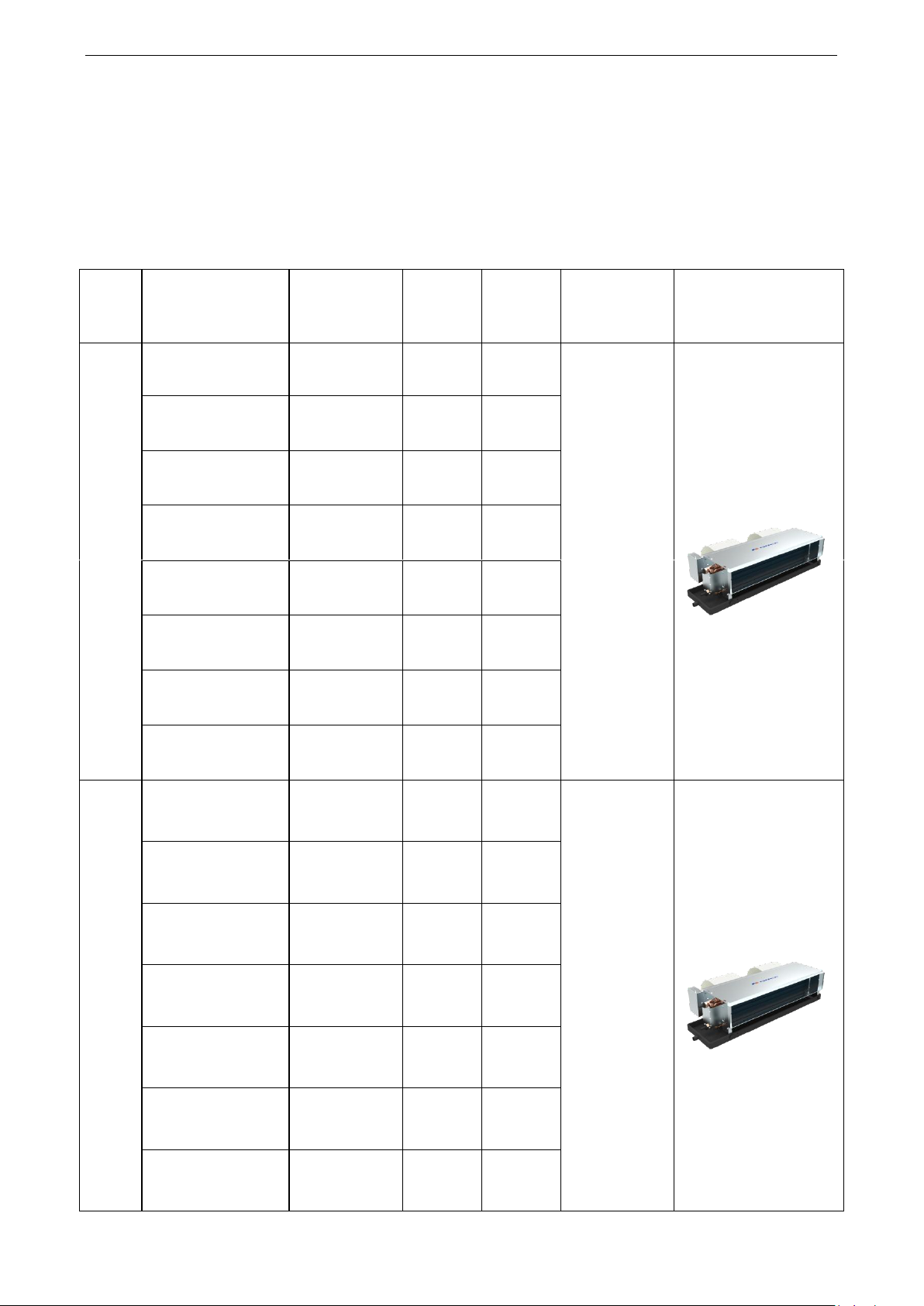
G Series FCU
FP-34WA/G-K
EM51002750
EM51002070
1.85/0.53
3.05/0.87
220-240V 50HZ
FP-51WA/G-K
EM51002140
EM51002790
2.8/0.8
4.22/1.2
FP-68WA/G-K
EM51002830
EM51002580
3.6/1.02
5.5/1.56
FP-85WA/G-K
EM51002210
EM51002870
4.5/1.28
7/1.99
FP-102WA/G-K
EM51002590
EM51002470
5.5/1.56
8.9/2.53
FP-136WA/G-K
EM51002630
EM51002490
7.35/2.09
12.1/3.44
FP-170WA/G-K
EM51002510
EM51002670
9.2/2.62
15.1/4.29
FP-204WA/G-K
EM51002710
EM51002100
11/3.13
18/5.12
G Series FCU
FP-34WAH/G-K
EM51002180
EM51002760
1.85/0.53
3.05/0.87
220-240V 50HZ
FP-51WAH/G-K
EM51002800
EM51002200
2.8/0.8
4.22/1.2
FP-68WAH/G-K
EM51002840
EM51002240
3.6/1.02
5.5/1.56
FP-85WAH/G-K
EM51002880
EM51002560
4.5/1.28
7/1.99
FP-102WAH/G-K
EM51002170
EM51002600
5.5/1.56
8.9/2.53
FP-136WAH/G-K
EM51002260
EM51002640
7.35/2.09
12.1/3.44
FP-170WAH/G-K
EM51002680
EM51002220
9.2/2.62
15.1/4.29
1. Product Introduction
1.1 Product Lineup
Section one --- countries and areas expect the European Union
50Hz (without the return air box) Standard, 3-row-pipes
2
Enginnering Data
FP-204WAH/G-K
EM51002530
EM51002530
11/3.13
18/5.12
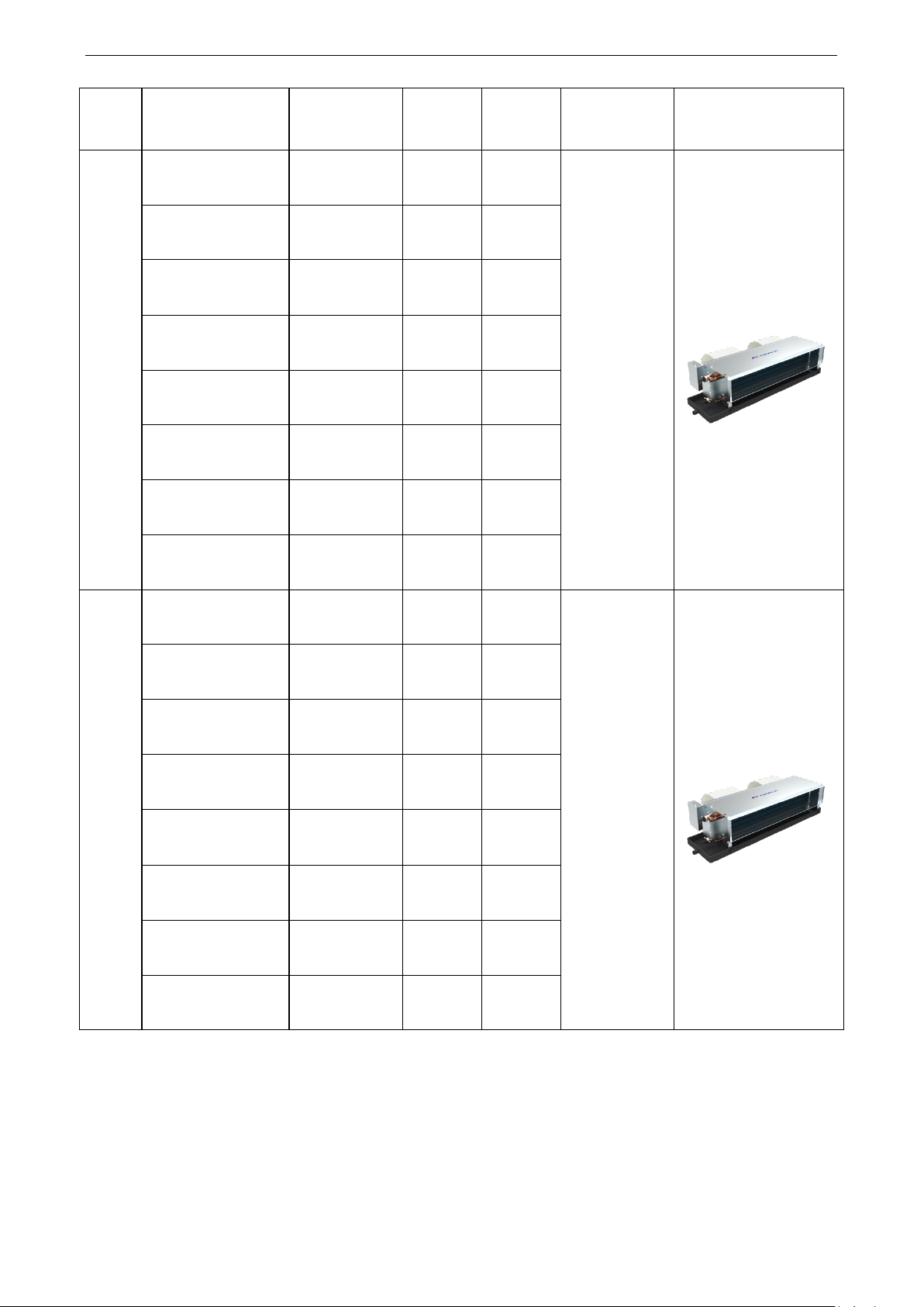
G Series FCU
FP-34WAS/G-K
EM51002080
EM51002780
2.25/0.64
3.6/1.02
220-240V 50HZ
FP-51WAS/G-K
EM51002820
EM51002110
3.3/0.94
5.9/1.68
FP-68WAS/G-K
EM51002230
EM51002860
4.3/1.22
7.3/2.08
FP-85WAS/G-K
EM51002900
EM51002190
5/1.42
8.05/2.29
FP-102WAS/G-K
EM51002480
EM51002600
6.3/1.79
10.1/2.87
FP-136WAS/G-K
EM51002250
EM51002660
8.2/2.33
13.2/3.75
FP-170WAS/G-K
EM51002700
EM51002520
9.8/2.79
15.8/4.49
FP-204WAS/G-K
EM51002550
EM51002740
11.25/3.2
18.6/5.29
G Series FCU
FP-34WAHS/G-K
EM51002770
EM51002130
2.25/0.64
3.6/1.02
220-240V 50HZ
FP-51WAHS/G-K
EM51002150
EM51002810
3.3/0.94
5.9/1.68
FP-68WAHS/G-K
EM51002120
EM51002850
4.3/1.22
7.3/2.08
FP-85WAHS/G-K
EM51002570
EM51002890
5/1.42
8.05/2.29
FP-102WAHS/G-K
EM51002610
EM51002160
6.3/1.79
10.1/2.87
FP-136WAHS/G-K
EM51002650
EM51002500
8.2/2.33
13.2/3.75
FP-170WAHS/G-K
EM51002090
EM51002690
9.8/2.79
15.8/4.49
FP-204WAHS/G-K
EM51002730
EM51002540
11.25/3.2
18.6/5.29
Note:1Ton =12000Btu/h = 3.517kW
3
Enginnering Data
Series
Model
Product Code
Cooling
Capacity
(kW/Ton)
Heating
Capacity
(kW/Ton)
Power Supply
Picture
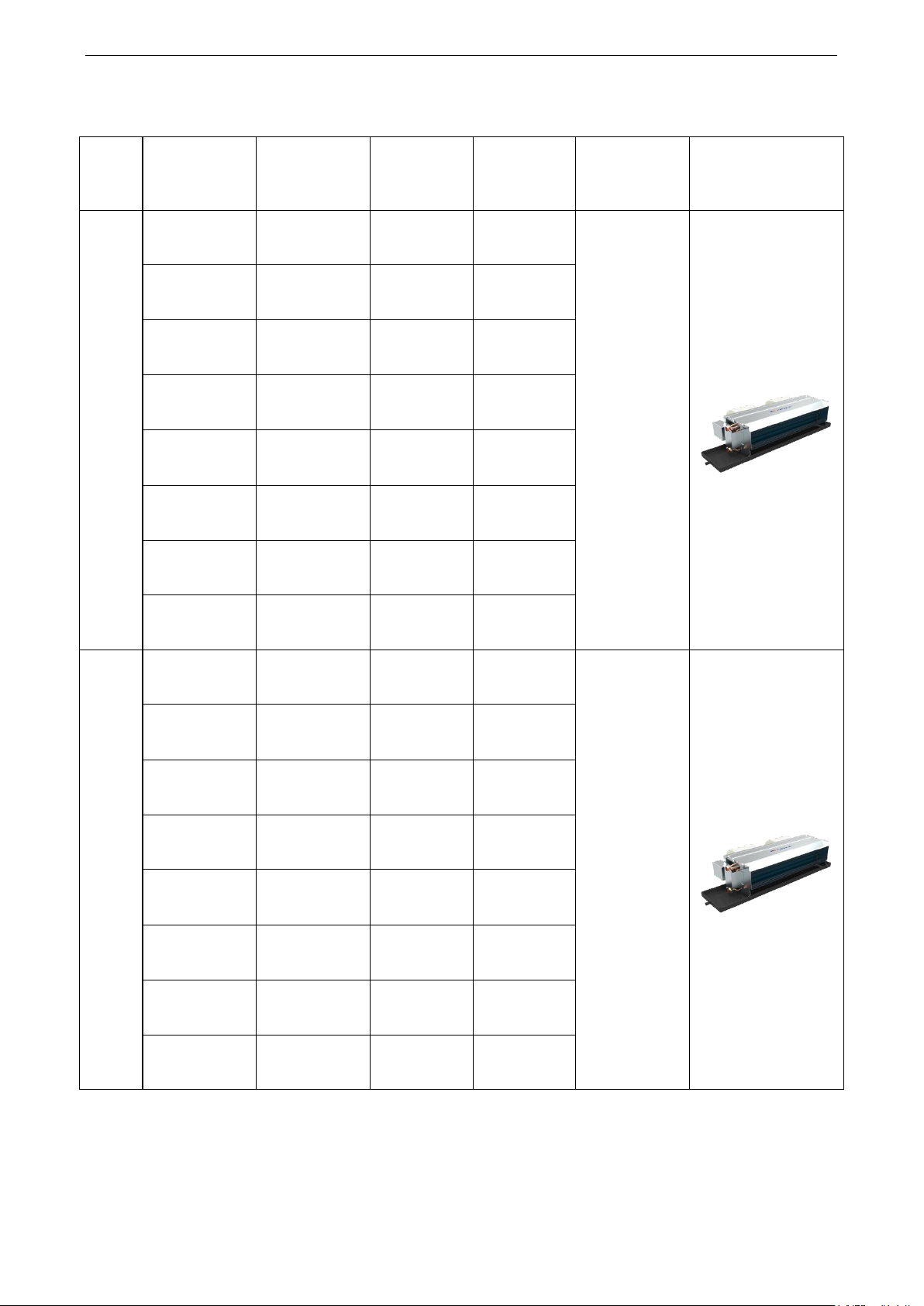
3+1 Series FCU
FP-34WAT-R
EM51000790
EM51001030
2.30/0.65
2.10/0.60
220-240V 50HZ
FP-51WAT-R
EM51000800
EM51001040
3.60/1.02
3.35/0.95
FP-68WAT-R
EM51000810
EM51001050
4.35/1.24
4.00/1.14
FP-85WAT-R
EM51000820
EM51001060
5.40/1.54
4.60/1.31
FP-102WAT-R
EM51000830
EM51001070
6.70/1.91
5.35/1.52
FP-136WAT-R
EM51000840
EM51001080
8.10/2.30
7.00/1.99
FP-170WAT-R
EM51000850
EM51001090
10.35/2.94
8.30/2.36
FP-204WAT-R
EM51000860
EM51001100
11.00/3.13
8.95/2.54
4 Series FCU
FP-34WAF-R
EM51000710
EM51001110
2.60/0.74
4.30/1.22
220-240V 50HZ
FP-51WAF-R
EM51000720
EM51001120
4.00/1.14
6.50/1.85
FP-68WAF-R
EM51000730
EM51001130
4.70/1.34
7.30/2.08
FP-85WAF-R
EM51000740
EM51001140
5.60/2.13
8.60/2.45
FP-102WAF-R
EM51000750
EM51001150
7.50/2.13
10.50/2.99
FP-136WAF-R
EM51000760
EM51001160
9.20/2.62
14.50/4.12
FP-170WAF-R
EM51000770
EM51001170
11.00/3.13
18.00/5.12
FP-204WAF-R
EM51000780
EM51001180
12.20/3.47
20.00/5.69
50Hz (without the return air box), standard, 3+1 or 4-row-pipes
4
Note:1Ton =12000Btu/h = 3.517kW
Enginnering Data
Series
Model
Product Code
Cooling capacity
(kW/Ton)
Heating capacity
(kW/Ton)
Power supply
Pictures
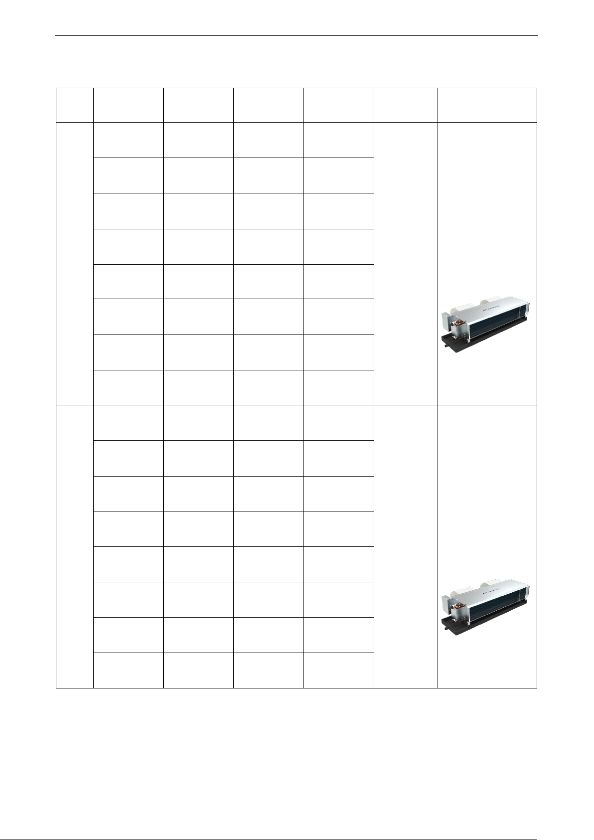
G
FP-34WA/G-D
EM51002350
EM51003310
1.9/0.54
3.05/0.87
208-230V
60HZ
FP-51WA/G-D
EM51002390
EM51003390
3/0.85
5/1.42
FP-68WA/G-D
EM51003430
EM51003440
3.6/1.02
5.9/1.68
FP-85WA/G-D
EM51003530
EM51002450
4.7/1.34
7.7/2.19
FP-102WA/G-D
EM51002920
EM51002910
5.7/1.62
9.35/2.66
FP-136WA/G-D
EM51003020
EM51003010
7.35/2.09
12.1/3.44
FP-170WA/G-D
EM51003120
EM51002300
9.5/2.7
15.8/4.49
FP-204WA/G-D
EM51002340
EM51003200
11.5/3.27
18.8/5.35
G
FP-34WAH/G-D
EM51003340
EM51002360
1.9/0.54
3.05/0.87
208-230V
60HZ
FP-51WAH/G-D
EM51002400
EM51003400
3/0.85
5/1.42
FP-68WAH/G-D
EM51003480
EM51003470
3.6/1.02
5.9/1.68
FP-85WAH/G-D
EM51002460
EM51003560
4.7/1.34
7.7/2.19
FP-102WAH/G-D
EM51002960
EM51002950
5.7/1.62
9.35/2.66
FP-136WAH/G-D
EM51003050
EM51002290
7.35/2.09
12.1/3.44
FP-170WAH/G-D
EM51002310
EM51003150
9.5/2.7
15.8/4.49
FP-204WAH/G-D
EM51003240
EM51003230
11.5/3.27
18.8/5.35
60HZ (without the return air box), standard
5
Enginnering Data
Series
Model
Product Code
Cooling
capacity
(kW/Ton)
Heating
capacity
(kW/Ton)
Power
supply
Pictures
G
FP-34WAS/G-D
EM51003380
EM51002380
2.25/0.64
3.7/1.05
208-230V
60HZ
FP-51WAS/G-D
EM51002420
EM51003420
3.3/0.94
5.4/1.54
FP-68WAS/G-D
EM51003520
EM51002440
4.4/1.25
7.35/2.09
FP-85WAS/G-D
EM51003620
EM51003610
5.2/1.48
8.5/2.42
FP-102WAS/G-D
EM51003000
EM51002280
6.6/1.88
10.65/3.03
FP-136WAS/G-D
EM51003110
EM51003100
8.3/2.36
13.5/3.84
FP-170WAS/G-D
EM51002330
EM51003190
10.2/2.9
17/4.83
FP-204WAS/G-D
EM51003300
EM51003290
12.2/3.47
20/5.69
G
FP-34WAHS/G-D
EM51002370
EM51003370
2.25/0.64
3.7/1.05
208-230V
60HZ
FP-51WAHS/G-D
EM51003410
EM51002410
3.3/0.94
5.4/1.54
FP-68WAHS/G-D
EM51002430
EM51003510
4.4/1.25
7.35/2.09
FP-85WAHS/G-D
EM51003600
EM51003590
5.2/1.48
8.5/2.42
FP-102WAHS/G-D
EM51002270
EM51002990
6.6/1.88
10.65/3.03
FP-136WAHS/G-D
EM51003090
EM51003080
8.3/2.35
13.5/3.84
FP-170WAHS/G-D
EM51003180
EM51002320
10.2/2. 9
17/4.83
FP-204WAHS/G-D
EM51003280
EM51003270
12.2/3.47
20/5.69
60HZ (without the return air box), 3-row-pipes
6

Enginnering Data
Series
Model
Product Code
Cooling
Capacity
(kW/Ton)
Heating
Capacity
(kW/Ton)
Power Supply
Picture
3+1 Series FCU
FP-34WAT-R
EM51000790
EM51001030
2.35/0.67
2.15/0.61
208~230V
60HZ
FP-51WAT-R
EM51000800
EM51001040
3.80/1.08
3.40/0.97
FP-68WAT-R
EM51000810
EM51001050
4.40/1.25
4.10/1.17
FP-85WAT-R
EM51000820
EM51001060
5.60/1.59
4.70/1.34
FP-102WAT-R
EM51000830
EM51001070
6.80/1.93
5.60/1.59
FP-136WAT-R
EM51000840
EM51001080
8.20/2.33
7.20/2.05
FP-170WAT-R
EM51000850
EM51001090
10.50/2.99
8.40/2.39
FP-204WAT-R
EM51000860
EM51001100
11.20/3.18
9.10/2.59
4 Series FCU
FP-34WAF-R
EM51000710
EM51001110
2.65/0.75
4.35/1.24
208~230V
60HZ
FP-51WAF-R
EM51000720
EM51001120
4.08/1.16
6.55/1.86
FP-68WAF-R
EM51000730
EM51001130
4.80/1.36
7.40/2.10
FP-85WAF-R
EM51000740
EM51001140
5.80/ 1.65
8.80/2.50
FP-102WAF-R
EM51000750
EM51001150
7.60/2.16
11.50/3.27
FP-136WAF-R
EM51000760
EM51001160
9.30/2.64
14.70/4.18
FP-170WAF-R
EM51000770
EM51001170
11.20/3.18
18.20/5.17
FP-204WAF-R
EM51000780
EM51001180
12.50/3.55
20.80/5.91
60Hz (without the return air box), 3+1 or 4-row-pipes
Note:1Ton =12000Btu/h = 3.517kW
7
Enginnering Data
Series
Model
Product Code
Cooling
capacity
(
kW/Ton)
Heating
capacity
(
kW/Ton)
Power
supply
Pictures
G
FP-34WA/GHL-K
EM51003330
EM51003320
1.75/0.5
2.2/0.63
220-240V
50HZ
FP-51WA/GHL-K
EM51003980
EM51003970
2.9/0.82
3.4/0.97
FP-68WA/GHL-K
EM51003460
EM51003450
3.4/0.97
4.2/1.19
FP-85WA/GHL-K
EM51003550
EM51003540
4.3/1.22
4.7/1.34
FP-102WA/GHL-K
EM51002940
EM51002930
4.9/1.39
6/1.71
FP-136WA/GHL-K
EM51003040
EM51003030
6.7/1.91
8/2.27
FP-170WA/GHL-K
EM51003140
EM51003130
7/1.99
9/2.56
FP-204WA/GHL-K
EM51003220
EM51003210
10/2.84
11.9/3.38
G
FP-34WAH/GHL-K
EM51003360
EM51003350
2/0.57
2.3/0.65
220-240V
50HZ
FP-51WAH/GHL-K
EM51003950
EM51003960
3.1/0.88
3.5/1
FP-68WAH/GHL-K
EM51003500
EM51003490
3.55/1.01
4.5/1.28
FP-85WAH/GHL-K
EM51003580
EM51003570
4.5/1.28
4.9/1.39
FP-102WAH/GHL-K
EM51002980
EM51002970
5.2/1.48
6.3/1.79
FP-136WAH/GHL-K
EM51003070
EM51003060
6.9/1.96
8.2/2.33
FP-170WAH/GHL-K
EM51003170
EM51003160
7.2/2.04
9.2/2.61
FP-204WAH/GHL-K
EM51003260
EM51003250
10.2/2.9
12/3.4
G
FP-34WAS/GHL-K
EM51003820
EM51003810
2.1/0.6
2.4/0.68
220-240V
50HZ
FP-51WAS/GHL-K
EM51003930
EM51003940
3.2/0.91
3.7/1.05
FP-68WAS/GHL-K
EM51003860
EM51003850
4.1/1.17
4.8/1.36
FP-85WAS/GHL-K
EM51003900
EM51003890
4.8/1.36
5.5/1.56
Section two --- countries and areas within the European Union
50HZ (with the return air box), standard, 3-row pipes
8
Enginnering Data
FP-102WAS/GHL-K
EM51003660
EM51003650
5.9/1.67
6.6/1.88
FP-136WAS/GHL-K
EM51003700
EM51003690
7.6/2.16
8.9/2.53
FP-170WAS/GHL-K
EM51003740
EM51003730
8.8/2.5
10.2/2.89
FP-204WAS/GHL-K
EM51003780
EM51003770
10.4/2.96
12.1/3.43
G
FP-34WAHS/GHL-K
EM51003800
EM51003790
2.5/0.71
2.8/0.8
220-240V
50HZ
FP-51WAHS/GHL-K
EM51003910
EM51003920
3.3/0.94
3.8/1.08
FP-68WAHS/GHL-K
EM51003840
EM51003830
4.2/1.19
5.1/1.45
FP-85WAHS/GHL-K
EM51003880
EM51003870
4.9/1.39
5.7/1.62
FP-102WAHS/GHL-K
EM51003640
EM51003630
6.1/1.73
6.9/1.96
FP-136WAHS/GHL-K
EM51003680
EM51003670
7.8/2.22
9 /2.55
FP-170WAHS/GHL-K
EM51003720
EM51003710
9/2.56
10.9/3.1
FP-204WAHS/GHL-K
EM51003760
EM51003750
10.5/2.99
12.4/3.53
Series
Model
Product Code
Cooling
Capacity
(kW/Ton)
(kW/Ton)
Power Supply
Picture
3+1 Series FCU
FP-34WAHT/BHL-K
EM51004030
EM51004080
2.45/0.70
3.40/0.97
220-240V
50HZ
FP-51WAHT/BHL-K
EM51004300
EM51004290
3.70/1.05
4.70/1.34
FP-68WAHT/BHL-K
EM51004340
EM51004330
4.55/1.29
5.70/1.62
FP-85WAHT/BHL-K
EM51004380
EM51004370
5.40/1.54
6.35/1.81
FP-102WAHT/BHL-K
EM51004120
EM51004110
6.35/1.81
7.55/2.15
FP-136WAHT/BHL-K
EM51004160
EM51004150
8.30/2.36
9.90/2.81
FP-170WAHT/BHL-K
EM51004200
EM51004190
10.00/2.84
11.50/3.27
50Hz (with the return air box), 3+1 or 4-row-pipes
9
Enginnering Data
FP-204WAHT/BHL-K
EM51004240
EM51004230
10.2/2.90
11.90/3.38
4 Series FCU
FP-34WAHF/BHL-K
EM51004260
EM51004250
2.65/0.75
3.15/0.90
220-240V
50HZ
FP-51WAHF/BHL-K
EM51004280
EM51004270
3.80/1.08
4.40/1.25
FP-68WAHF/BHL-K
EM51004320
EM51004310
5.00/1.42
5.45/1.55
FP-85WAHF/BHL-K
EM51004360
EM51004350
5.70/1.62
6.15/1.75
FP-102WAHF/BHL-K
EM51004100
EM51004090
7.10/2.02
7.30/2.08
FP-136WAHF/BHL-K
EM51004140
EM51004130
8.90/2.53
9.50/2.70
FP-170WAHF/BHL-K
EM51004180
EM51004170
11.00/3.13
12.30/3.50
FP-204WAHF/BHL-K
EM51004220
EM51004210
11.20/3.18
13.00/3.70
Note:1Ton =12000Btu/h = 3.517kW
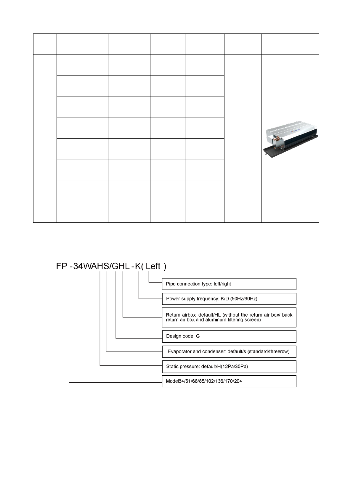
1.2 Nomenclature
10
Enginnering Data
1.3 Product Features
1.3.1 Features
FCU is the most widely used terminal unit of the air conditioning system, used fo supplying cooling
(hot) water, with the air flow below 2500m3/h and the external static pressure less than 100Pa. For
cooling, enthalpy loss of the air generally is 15.9kJ/kg. For hot water under 60℃, the cheating capacity is
1.5 times of the cooling capacity.
As the terminal unit of the central air conditioning system, it is widely used in public areas with the
following main features:
a. Three speeds are selectable for the air flow. According to the set point of the room temperature,
the water system can be controlled by the hot/cool water automatic regulating valve so that
temperature for each room can be controlled separately for meeting different requirements.
Where no one is inside the room, it can be turned off manually or by the timing function, which
will lower the operation cost of the whole system.
b. The zone control is available based on direction, height, utilization and service time, which can
avoid unreasonable conceptualized control of the large-sized duct system.
c. Compact structure, flexible arrangement, and easy installation will save installation space and
facilitate indoor decoration.
There are various structures with the same air flow and cooling capacity for different room structure,
different decoration and duct arrangement.
(1) Plastic Fan
a. Light-weighted, which will lead to increased air flow driven by the same motor.
b. Good compatibility of the angle of the blades and the cavity of the volute, which will lead to silent
operation.
c. CFD designed flow and angle of fan blades, for high operation efficiency
d. The volute is divided into the upper and lower parts, which will facilitate disassembly.
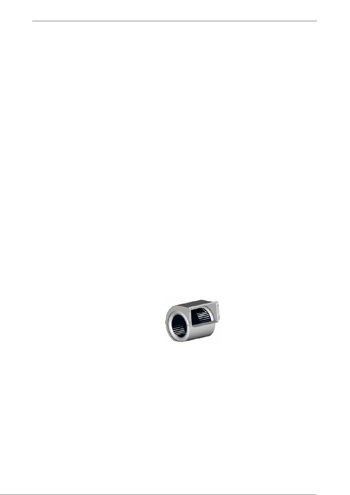
(2) CFD Designed Fan
a. Optimized flow structure
b. Evenly distributed air flow and low flow noise
c. less eddy flow
d. Novel style and advanced structure
e. Decreased height , saving installation space
f. Low noise and three fan speeds
g. High-quality material and strict processing control for guaranteeing quality and service life of
the whole unit.
h. Die formed drain pan with the entirely pressured and pasted insulation, generating no
11
Enginnering Data
condensate
i. Optimized location of the exhaust and drain valves, for better heat exchanging effect and
preventing from frost cracks in winter.
(3) High-efficiency copper tubes
The copper tubes are made of pure red copper with female threads on the inner wall. There are also
raised teeth at the inner wall, used for increasing turbulent flows and damaging the boundary layer of
water for better heat exchanging capacity.
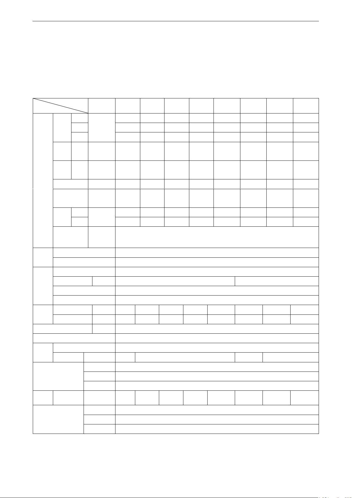
(4) The Cooler with the Interchangeable Left/Right Structure
During installation, the left-type and right-type structure can be selected flexibly as steps stated below:
Step 1: Remove the centrifugal fan, cover plate and screws of the electric box.
Step 2: Move the side plate at the air outlet to the other side.
Step 3: Rotate the fan assembly and the cover plate for 180°and then fix them.
Step 4: Remove the electric box to the other side and then fix it..
1.: Cover plate; 2. Centrifugal fan; 3. Side plate at the air outlet
Left-type Unit Right-type Unit
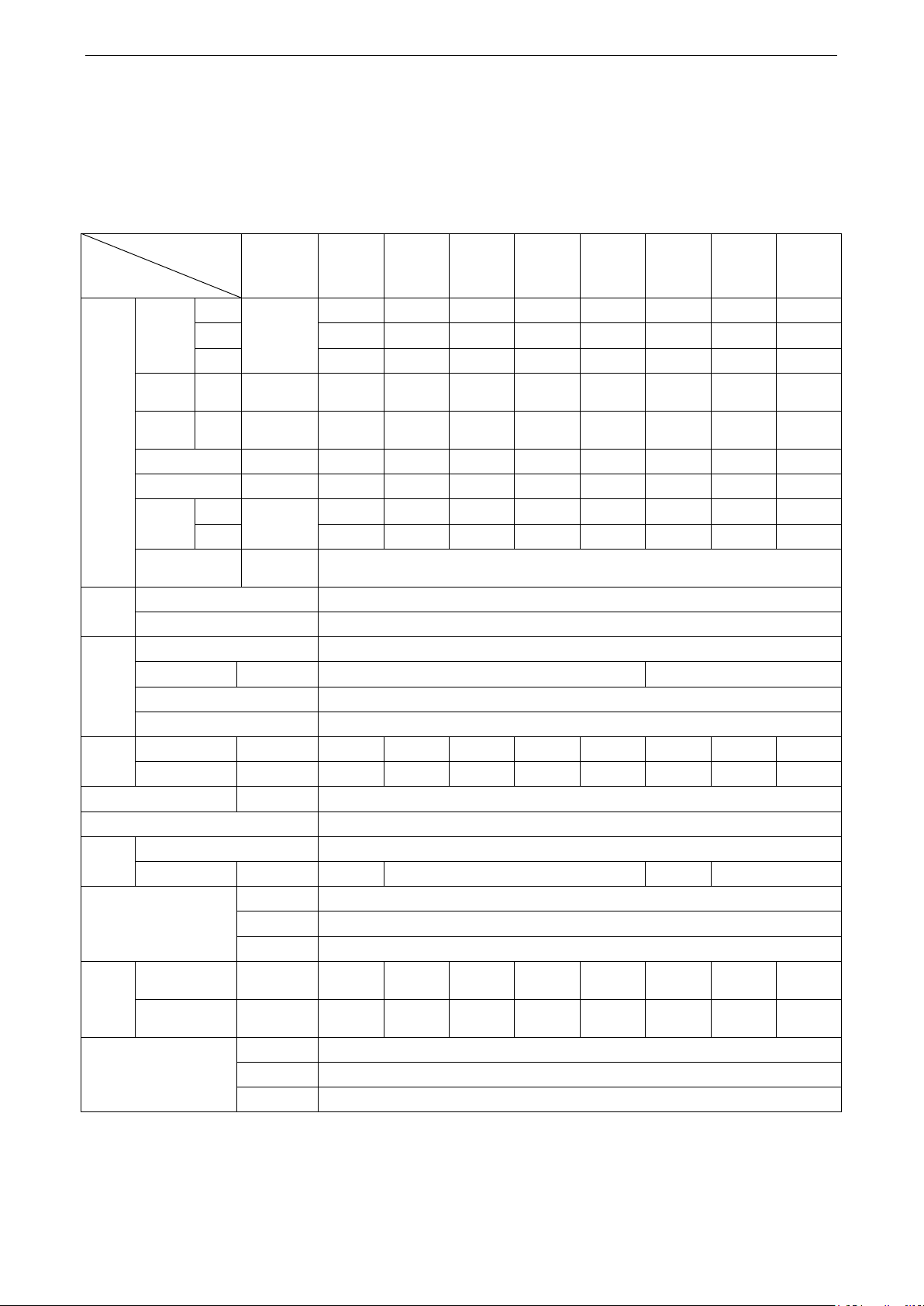
1.4 Working Principle
The cool (hot) water goes in the fan coil and makes heat exchanging with the indoor circulated air
(outdoor air), to realize cooling(heating), dehumidifying, filtrating or purifying. The processed air will be
supplied to indoor directly or by air duct.
12
Enginnering Data
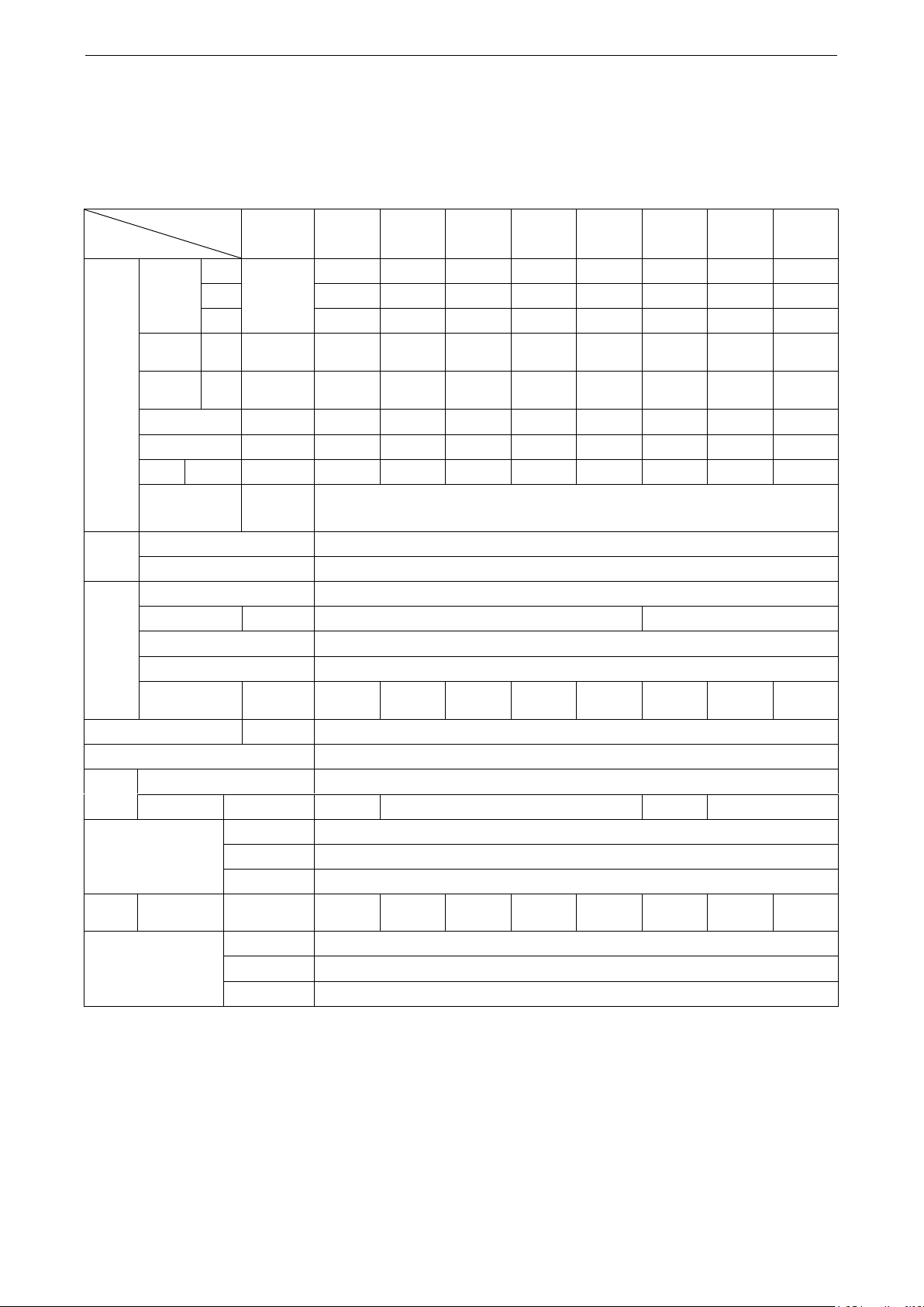
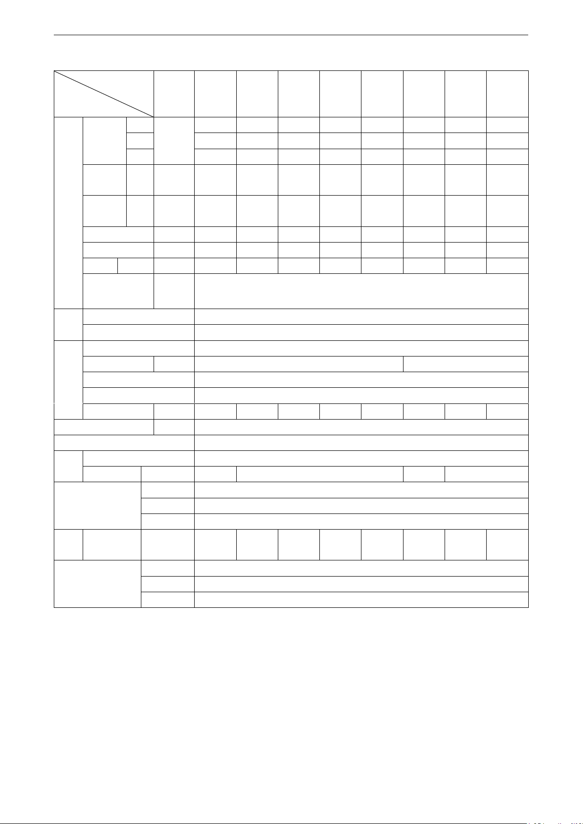
Type
Item
Concealed
ceiling type
FP-34WA/
G-K
FP-51WA/
G-K
FP-68WA/
G-K
FP-85WA/
G-K
FP-102WA/
G-K
FP-136WA/
G-K
FP-170WA/
G-K
FP-204WA/
G-K
Performance
Airflow
Hi
m3/h
340
510
680
850
1020
1360
1700
2040
Mid
248
393
510
638
788
1095
1275
1575
Low
213
263
340
425
525
730
850
1050
Cooling
capacity
Hi W 1850
2800
3600
4500
5500
7350
9200
11000
Heating
capacity
Hi W 3050
4620
5940
7400
9000
12100
15100
18100
Flow rate
m3/h
0.33
0.52
0.63
0.77
0.92
1.31
1.52
1.92
Water
resistance
kPa
15
30
23
25
35
40
46
40
Noise
12pa
dB(A)
34.5
35
40
40.5
44
45
46
49
30Pa
36
37
41
42
45.5
46
47.5
51
External static
pressure
Pa
12Pa for the standard type (with no diffuser and filter ); 30Pa for the high ESP type
Coil
Type
Copper, high-efficiency louvered fins
Pressure
≤1.6MPa
Motor
Type
Class B, capacitor start
Quantity
/
1
2
Power supply
220-240V~ 50Hz
Protection class
IP20
Input
power
12pa
W
37
52
62
76
96
134
152
189
30Pa
W
44
59
72
87
108
156
174
212
Power lines
mm2
0.5×3
Protection class
I
Fan
Type
Front-forward multi-vane low-noise centrifugal fan
Quantity
/
1 2 3
4
Connection pipe
Inlet water
Rc3/4(female thread)
Outlet water
Rc3/4(female thread)
Condensate
R23/4(female thread)
Weight
Without return
air box
kg
11.2
13
14.3
15.5
16.6
23
26.2
28
Thermostat (optional)
Mechanical
Z54352A1
Digit
WK-110PA0
Deluxe digit
WK-010PA-K-K
1.5 Technical Data
1.5.1 Data at Nominal Conditions
Section one --- countries and areas except the European Union
(1) 50Hz (without the return air box), standard, 3-row pipes
Standard Type (G Series)
Notes:
a) The left and right modes can be switched over on site. The correction coefficient for both
cooling and heating is 0.9.
13
b) Nominal cooling conditions: (27/19.5℃) indoor dry/wet bulb temperature, (7/12℃) entering
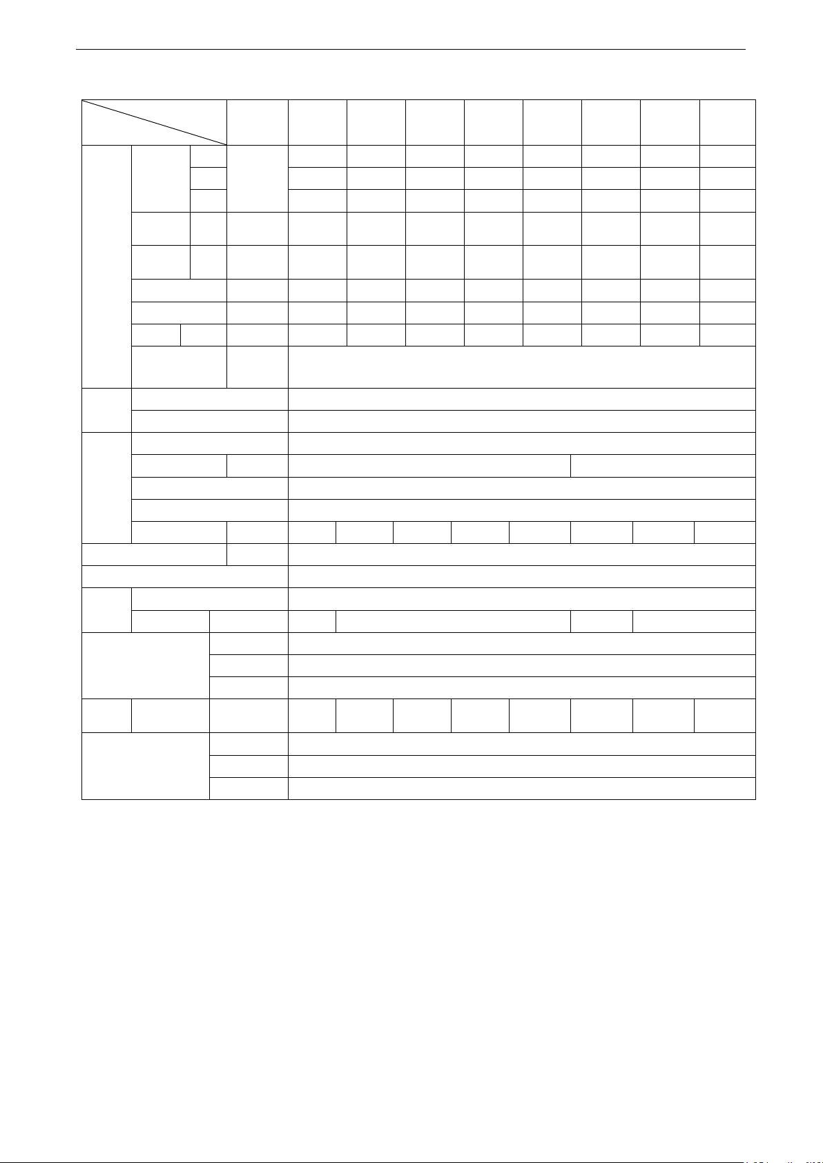
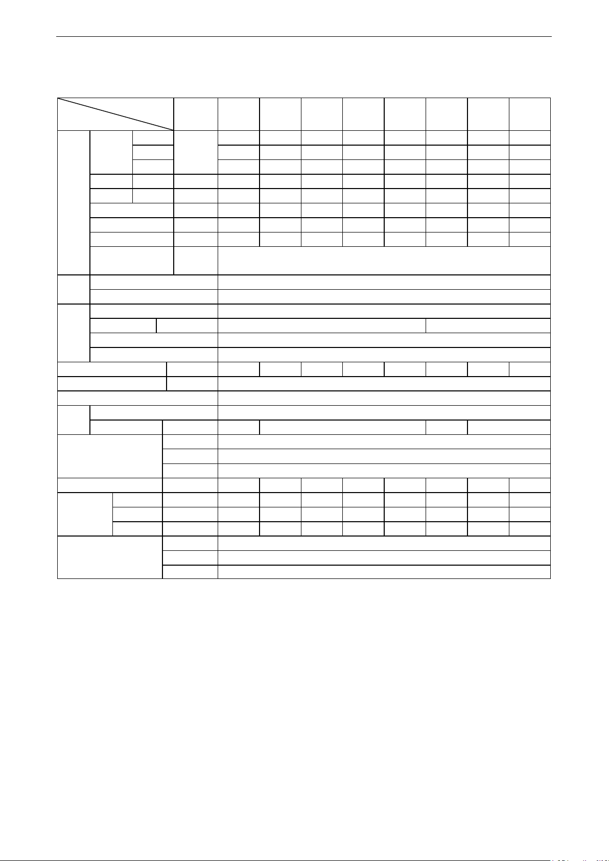
Model
Item
Concealed
ceiling type
FP-34W
AS/G-K
FP-51W
AS/G-K
FP-68W
AS/G-K
FP-85W
AS/G-K
FP-102
WAS/G-
K
FP-136
WAS/G-
K
FP-170
WAS/G-
K
FP-204
WAS/G-
K
Performance
Air flow
Hi
m3/h
340
510
680
850
1020
1360
1700
2040
Mid
248
394
495
638
788
1095
1275
1575
Low
173
263
330
425
525
730
850
1050
Cooling
capacity
Hi W 2250
3300
4300
5000
6300
8200
9800
11250
Heating
capacity
Hi W 3600
5300
6930
8050
10100
13200
15800
18600
Water flow
m3/h
0.4
0.57
0.76
0.88
0.99
1.41
1.68
1.95
Water resistance
kPa
20
21
22
30
35
40
33
40
Noise
12pa
dB(A)
34.5
37
38.5
41
44
45
46.5
50
30Pa
36
38
41
43
46
47
47.5
51.5
External static
pressure
Pa
12Pa for the standard type (with no diffuser and filter ); 30Pa for the high ESP type
Coil
Type
Copper, high-efficiency louvered fins
Pressure
≤1.6MPa
Motor
Type
Class B, capacitor start
Quantity
/
1
2
Power supply
220V~ 50Hz
Protection class
IP20
Input
power
12pa
W
37
52
62
76
96
134
152
189
30Pa
W
44
59
72
87
108
156
174
212
Power lines
mm2
0.5×3
Protection class
I
Fan
Type
Front-forward multi-vane low-noise centrifugal fan
Quantity
/
1 2 3
4
Connection pipe
Inlet water
Rc3/4(female thread)
Outlet water
Rc3/4(female thread)
Condensate
R2c3/4(female thread)
Weight
Without the
return air box
kg
11.6
13.4
14.7
16
17.4
24
26.6
28.5
With the return
air box
kg
Thermostat (optional)
Mechanical
Z54352A1
Digit
WK-110PA0
Deluxe digit
WK-010PA-K-K
and leaving water temperature. Nominal heating conditions: 21℃ indoor dry bulb
temperature, 60℃ entering water temperature.
c) The noise is tested under the semi-anechoic chamber and the actual value will change
under different environments.
Three-row type
Enginnering Data
Notes:
a) The left and right modes can be switched over on site. The correction coefficient for both
cooling and heating is 0.9.
b) Nominal cooling conditions: (27/19.5℃) indoor dry/wet bulb temperature, (7/12℃) entering
14
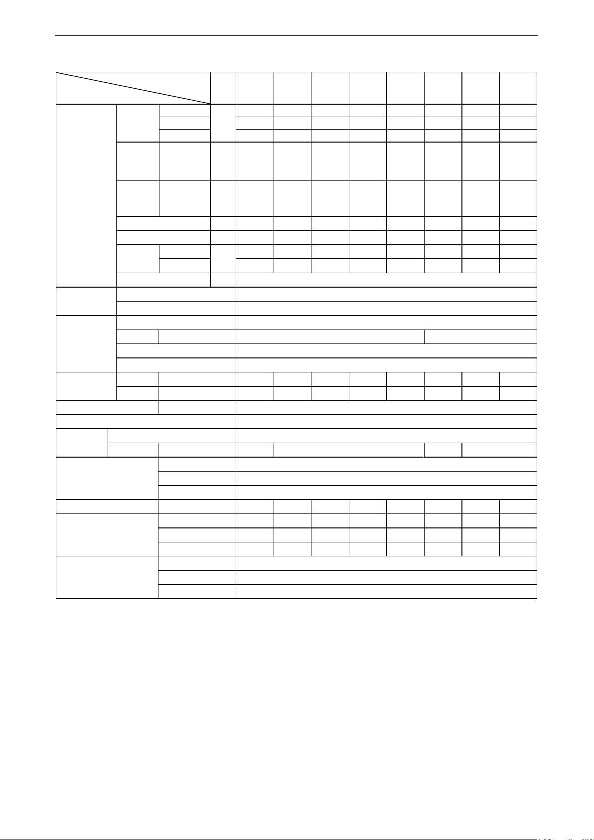
Enginnering Data
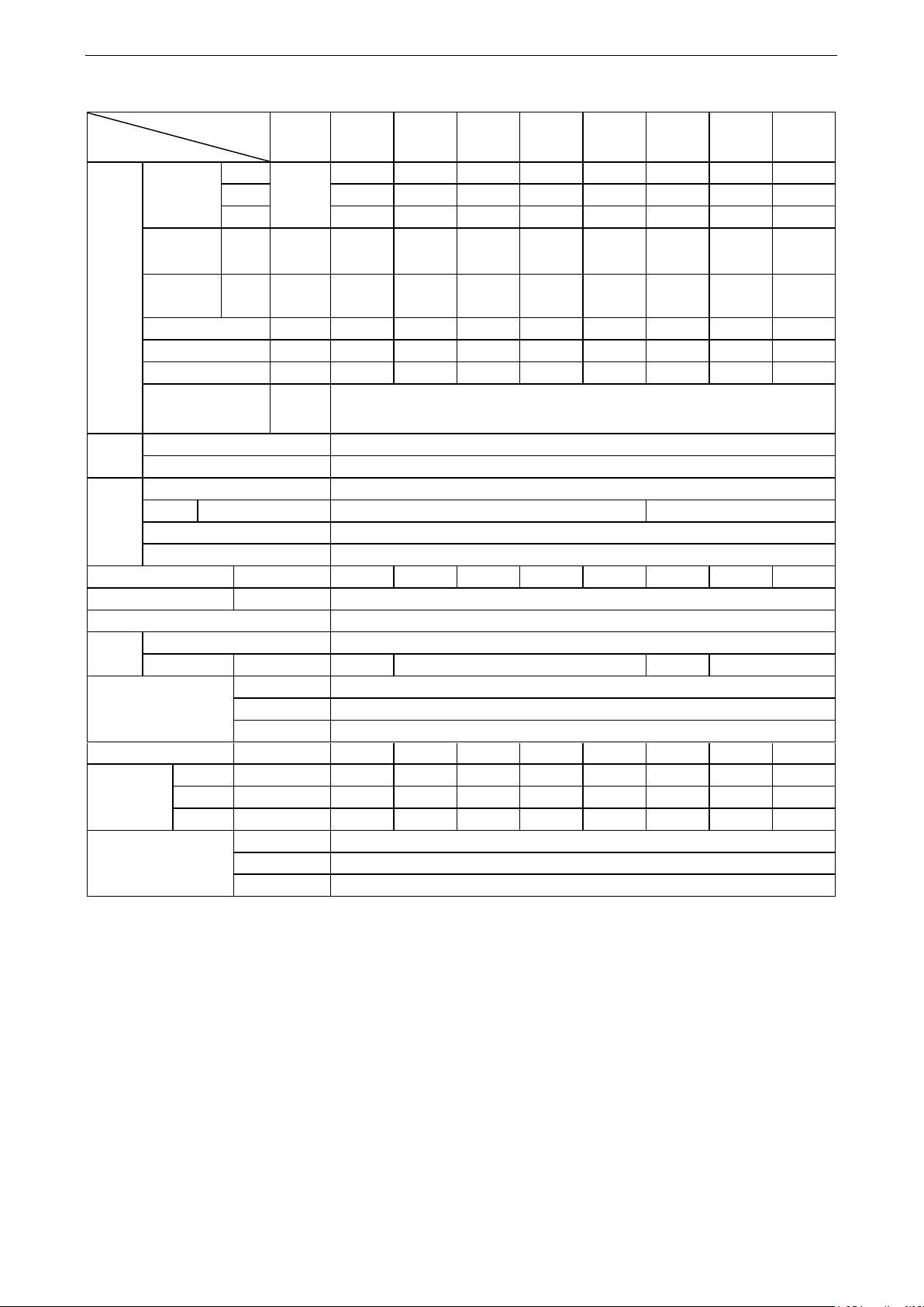
Type
Item
Concealed
ceiling type
FP-34WA
F-R
FP-51WA
F-R
FP-68WA
F-R
FP-85WA
F-R
FP-102W
AF-R
FP-136W
AF-R
FP-170W
AF-R
FP-204W
AF-R
Performance
Airflow
Hi
m3/h
340
510
680
850
1020
1360
1700
2040
Mid
248
393
510
638
788
1095
1275
1575
Low
213
263
340
425
525
730
850
1050
Cooling
capacity
Hi W 2600
4000
4700
5600
7500
9200
11000
12200
Heating
capacity
Hi W 4300
6500
7300
8600
10500
14500
18000
20000
Flow rate
m3/h
0.464
0.729
0.893
0.981
1.318
1.615
2.042
2.229
Water resistance
kPa
3.713
8.943
14.54
18.79
35.75
19.06
29.01
35.41
Noise
30Pa
40
42
44
46
47
48
50
52
External static
pressure
Pa
30pa
Coil
Type
Copper, high-efficiency louvered fins
Pressure
≤1.6MPa
Motor
Type
Class B, capacitor start
Quantity
/
1
2
Power supply
220-240V~ 50Hz
Protection class
IP20
Input power
30Pa
W
43
59
70
84
105
151
174
206
Power lines
mm2
0.5×3
Protection class
I
Fan
Type
Front-forward multi-vane low-noise centrifugal fan
Quantity
/
1 2 3
4
Connection pipe
Inlet water
Rc3/4(female thread)
Outlet water
Rc3/4(female thread)
Condensate
R23/4(female thread)
Weight
Without return
air box
kg
14.4
17.2
19.2
20.5
23.2
34.2
37.5
37.5
Thermostat (optional)
Mechanical
Z54352A1
Digit
WK-110PA0
Digital (deluxe)
WK-010PA-K-K
and leaving water temperature. Nominal heating conditions: 21℃ indoor dry bulb
temperature, 60℃ entering water temperature.
c) The noise is tested under the semi-anechoic chamber and the actual value will change
under different environments.
50Hz (without the return air box), 4-row pipes
Notes:
a) The left and right modes can be switched over on site. The correction coefficient for both
cooling and heating is 0.9.
b) Nominal cooling conditions: (27/19.5℃) indoor dry/wet bulb temperature, (7/12℃) entering
and leaving water temperature. Nominal heating conditions: 21℃ indoor dry bulb
temperature, 60℃ entering water temperature.
c) The noise is tested under the semi-anechoic chamber and the actual value will change
under different environments.
15
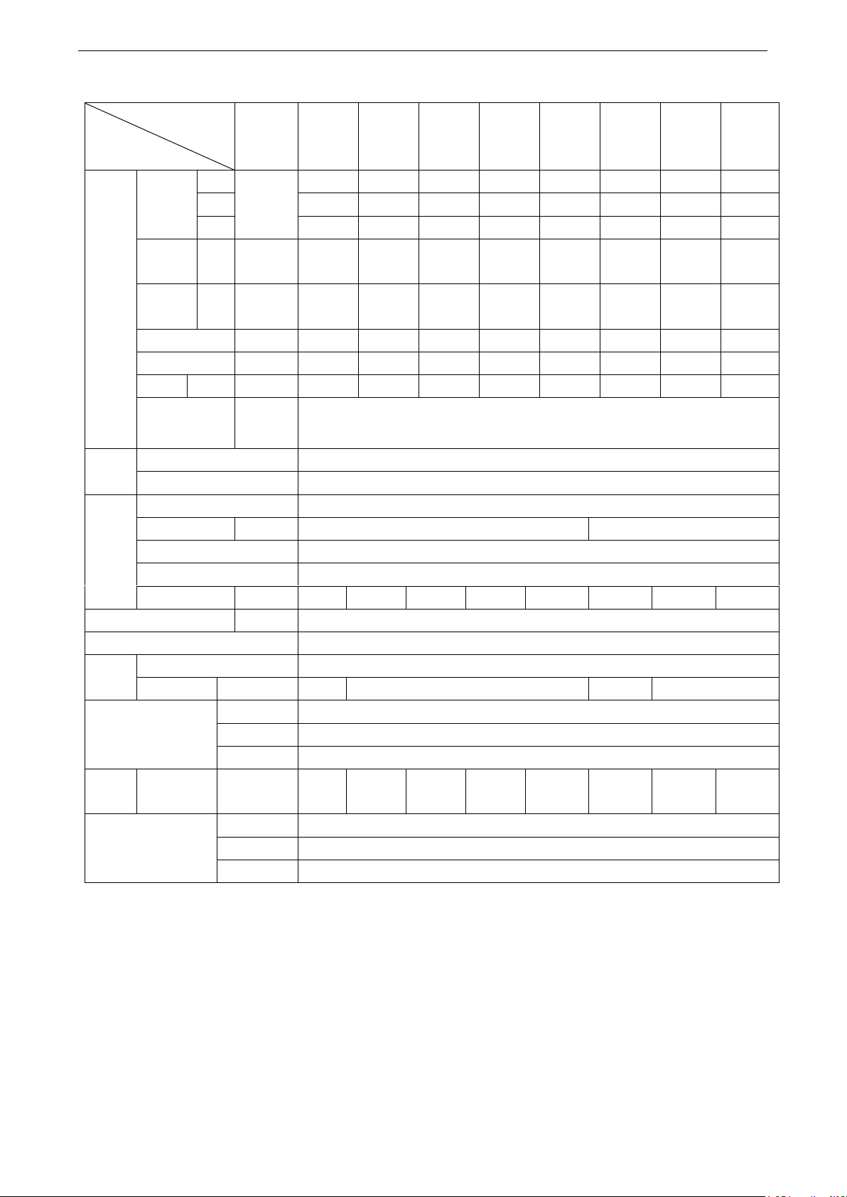
Enginnering Data
Type
Item
Concealed
ceiling type
FP-34WA
T-R
FP-51WA
T-R
FP-68WA
T-R
FP-85WA
T-R
FP-102W
AT -R
FP-136W
AT -R
FP-170W
AT -R
FP-204
WAT-R
Performance
Airflow
Hi
m3/h
340
510
680
850
1020
1360
1700
2040
Mid
248
393
510
638
788
1095
1275
1575
Low
213
263
340
425
525
730
850
1050
Cooling
capacity
Hi W 2300
3600
4350
5400
6700
8100
10350
11000
Heating
capacity
Hi W 2100
3350
4000
4600
5350
7000
8300
8950
Flow rate
m3/h
0.446
0.697
0.808
0.98
1.171
1.45
1.747
1.964
Water resistance
kPa
5.83
13.50
19.86
30.81
51.67
17.20
25.24
29.34
Noise
30Pa
40
42
44
46
47
48
50
52
External static
pressure
Pa
30pa
Coil
Type
Copper, high-efficiency louvered fins
Pressure
≤1.6MPa
Motor
Type
Class B, capacitor start
Quantity
/
1
2
Power supply
220-240V~ 50Hz
Protection class
IP20
Input power 30Pa
W
43
59
70
84
105
151
174
206
Power lines
mm2
0.5×3
Protection class
I
Fan
Type
Front-forward multi-vane low-noise centrifugal fan
Quantity
/
1 2 3
4
Connection pipe
Inlet water
Rc3/4(female thread)
Outlet water
Rc3/4(female thread)
Condensate
R23/4(female thread)
Weight
Without return
air box
kg
14.4
17.2
19.2
20.5
23.2
34.2
37.5
37.5
Thermostat (optional)
Mechanical
Z54352A1
Digit
WK-110PA0
Deluxe digit
WK-010PA-K-K
50Hz (without the return air box), 3+1-row pipes
Notes:
a) The left and right modes can be switched over on site. The correction coefficient for both
cooling and heating is 0.9.
b) Nominal cooling conditions: (27/19.5℃) indoor dry/wet bulb temperature, (7/12℃) entering
and leaving water temperature. Nominal heating conditions: 21℃ indoor dry bulb
temperature, 60℃ entering water temperature.
c) The noise is tested under the semi-anechoic chamber and the actual value will change
under different environments.
16

Enginnering Data
Model
Item
Unit
FP-34WA/
G-D
FP-51WA/
G-D
FP-68WA/
G-D
FP-85WA/
G-D
FP-102WA/
G-D
FP-136WA/
G-D
FP-170WA/
G-D
FP-204WA/
G-D
Performance
Air flow
High
m³/h
340
510
680
850
1020
1360
1700
2040
Medium
248
394
495
638
788
1095
1275
1575
Low
173
263
330
425
525
730
850
1050
Cooling
capacity
High W 1900
3000
3600
4700
5700
7350
9500
11500
Heating
capacity
High W 3050
5000
5900
7700
9350
12100
15800
18800
Water flow
m³/h
0.33
0.52
0.62
0.81
0.98
1.27
1.64
1.98
Water resistance
kPa
15
30
23
25
35
40
36
40
Noise
12pa
dB(A)
34.5
38
40
43
45
46
48
50
30Pa
36
39
42
46
47.5
48
50
52
ESP
Pa
12Pa for the standard type (without the air diffuser and filter)
30Pa for the high static pressure type
Coils
Type
Copper tube with lourved fins
Working pressure
≤1.6MPa
Motor
Type
Class B insulation, capacitor start
Quantity
Piece
1
2
Power supply
208-230VAC 60Hz
Protection class
IP20
Input
power
12pa W 36
57
70
104
105
164
180
228
30Pa
W
49
58
74
105
123
165
221
273
Power lines
mm2×piece
0.5×3
Anti electric shock class
I
Fan
Type
Forward multi-vane low-noise centrifugal fan
Quantity
piece
1 2 3
4
Connection pipe
Inlet
Rc3/4(inner thread)
Outlet
Rc3/4(inner thread)
Condensate
Rc3/4(outer thread)
Net weight
kg
11.2
13
14.3
15.5
16.6
23
26.2
28
Outline
dimensions
Width
mm
680
800
900
1000
1080
1380
1520
1620
Depth
mm
490
460
490
490
490
490
490
490
Height
mm
235
235
235
235
235
235
235
235
Thermostat (optional)
Mechanical
Z54352A1
Digital
WK-110PA0
Digital (deluxe)
WK-010PA-K-K
(2) 60Hz (without the return air box), standard, 3-row pipes
Horizontal concealed FCU— (G series, 208-230VAC 60Hz)
Notes:
a) The left and right modes can be switched over on site. The correction coefficient for both
cooling and heating is 0.9.
b) Nominal cooling conditions: (27/19.5℃) indoor dry/wet bulb temperature, (7/12℃) entering
and leaving water temperature. Nominal heating conditions: 21℃ indoor dry bulb
temperature, 60℃ entering water temperature.
c) The noise is tested under the semi-anechoic chamber and the actual value will change
under different environments.
17
Enginnering Data
Model
Item
Unit
FP-34WA
S/G-D
FP-51WA
S/G-D
FP-68WA
S/G-D
FP-85WA
S/G-D
FP-102W
AS/G-D
FP-136W
AS/G-D
FP-170W
AS/G-D
FP-204W
AS/G-D
Performance
Air flow
High
m³/h
340
510
680
850
1020
1360
1700
2040
Medium
248
394
495
638
788
1095
1275
1575
Low
173
263
330
425
525
730
850
1050
Cooling
capacity
High-speed
W
2250
3300
4400
5200
6600
8300
10200
12200
Heating
capacity
High-speed
W
3700
5400
7350
8500
10650
13500
17000
20000
Water flow
m³/h
0.39
0.57
0.76
0.90
1.14
1.43
1.76
2.10
Water resistance
kPa
20
21
22
30
35
40
33
40
Noise
12pa
dB(A)
35
39
41
43
46
46
48
50
30Pa
38
40
44
46
48
49
50
52
ESP
Pa
12Pa for the standard type (without the air diffuser and filter)
Coils
Type
Copper tube with lourved fins
Working pressure
≤1.6MPa
Motor
Type
Class B insulation, capacitor start
Quantity
Piece 1 2
Power lines
208-230VAC 60Hz
Protection class
IP20
Input power
12pa W 36
63
70
104
114
182
180
228
30Pa W 49
64
74
105
123
183
221
273
Power lines
mm2×piece
0.5×3
Anti electric shock class
I
Fan
Model
Forward multi-vane low-noise centrifugal fan
Quantity
piece
1 2 3
4
Connection pipe
Inlet
Rc3/4(inner thread)
Outlet
Rc3/4(inner thread)
Condensate
Rc3/4(outer thread)
Net weight
kg
11.6
13.4
14.7
16
17.4
24
26.6
28.5
Outline dimensions
Width
mm
680
800
900
1000
1080
1380
1520
Depth
mm
490
460
490
490
490
490
490
Height
mm
235
235
235
235
235
235
235
Thermostat (optional)
Mechanical
Z54352A1
Digital
WK-110PA0
Digital (deluxe)
WK-010PA-K-K
Horizontal concealed three-row-pipe FCU— (G series, 208-230VAC 60Hz)
Notes:
a) The left and right modes can be switched over on site. The correction coefficient for both
cooling and heating is 0.9.
b) Nominal cooling conditions: (27/19.5℃) indoor dry/wet bulb temperature, (7/12℃) entering
and leaving water temperature. Nominal heating conditions: 21℃ indoor dry bulb
temperature, 60℃ entering water temperature.
c) The noise is tested under the semi-anechoic chamber and the actual value will change
under different environments.
18
Enginnering Data
Type
Item
Concealed
ceiling type
FP-34WAF
-R
FP-51WAF
-R
FP-68WAF
-R
FP-85WAF
-R
FP-102WA
F-R
FP-136WA
F-R
FP-170WA
F-R
FP-204W
AF-R
Performance
Airflow
Hi
m3/h
340
590
690
820
1040
1490
1850
2160
Mid
248
393
510
638
788
1095
1275
1575
Low
213
263
340
425
525
730
850
1050
Cooling
capacity
Hi W 2650
4080
4800
5800
7600
9300
11200
12500
Heating
capacity
Hi W 4350
6550
7400
8800
11500
14700
18200
20800
Flow rate
m3/h
0.464
0.729
0.893
0.981
1.318
1.615
2.042
2.229
Water resistance
kPa
8
9
18
21
41
21
32
34
Noise
30Pa
40
42
44
46
47
48
50
52
External static
pressure
Pa
30pa
Coil
Type
Copper, high-efficiency louvered fins
Pressure
≤1.6MPa
Motor
Type
Class B, capacitor start
Quantity
/
1
2
Power supply
220-240V~ 50Hz
Protection class
IP20
Input power 30Pa
W
49
80
82
103
140
192
217
277
Power lines
mm2
0.5×3
Protection class
I
Fan
Type
Front-forward multi-vane low-noise centrifugal fan
Quantity
/
1 2 3
4
Connection pipe
Inlet water
Rc3/4(female thread)
Outlet water
Rc3/4(female thread)
Condensate
R23/4(female thread)
Weight
Without return
air box
kg
14.4
17.2
19.2
20.5
23.2
34.2
37.5
37.5
Thermostat (optional)
Mechanical
Z54352A1
Digit
WK-110PA0
Deluxe digit
WK-010PA-K-K
(3) 60 Hz (Without the return air box), 4-row pipes
19
Enginnering Data
Type
Item
Concealed
ceiling
type
FP-34WAT
-R
FP-51WAT
-R
FP-68WAT
-R
FP-85WAT
-R
FP-102WA
T-R
FP-136WA
T-R
FP-170WA
T-R
FP-204WA
T-R
Performance
Airflow
Hi
m3/h
360
630
690
890
1040
1490
1850
2160
Mid
248
393
510
638
788
1095
1275
1575
Low
213
263
340
425
525
730
850
1050
Cooling
capacity
Hi W 2350
3800
4400
5600
6800
8200
10500
11200
Heating
capacity
Hi W 2150
3400
4100
4700
5600
7200
8400
9100
Flow rate
m3/h
0.446
0.697
0.808
0.98
1.171
1.45
1.747
1.964
Water resistance
kPa
8
15
24
35
56
17
32
31
Noise
30Pa
40
42
44
46
47
48
50
52
External static
pressure
Pa
30pa
Coil
Type
Copper, high-efficiency louvered fins
Pressure
≤1.6MPa
Motor
Type
Class B, capacitor start
Quantity
/
1
2
Power supply
220-240V~ 50Hz
Protection class
IP20
Input power 30Pa
W
49
80
82
112
140
192
217
277
Power lines
mm2
0.5×3
Protection class
I
Fan
Type
Front-forward multi-vane low-noise centrifugal fan
Quantity
/
1 2 3
4
Connection pipe
Inlet water
Rc3/4(female thread)
Outlet water
Rc3/4(female thread)
Condensate
R23/4(female thread)
Weight
Without return
air box
kg
14.4
17.2
19.2
20.5
23.2
34.2
37.5
37.5
Thermostat (optional)
Mechanical
Z54352A1
Digit
WK-110PA0
Deluxe digit
WK-010PA-K-K
(4) 60 Hz (Without the return air box), 3+1-row pipes
20
Enginnering Data
Model
Item
Unit
FP-34WA/
GHL-K
FP-51WA/
GHL-K
FP-68WA/
GHL-K
FP-85WA/
GHL-K
FP-102WA
/GHL-K
FP-136WA
/GHL-K
FP-170WA
/GHL-K
FP-204WA
/GHL-K
Performance
Air flow
High
m³/h
370
570
720
870
1020
1360
1600
1900
Medium
260
400
504
610
788
1095
1120
1330
Low
180
280
353
426
525
730
784
931
Cooling
High W 1750
2900
3400
4300
4900
6700
7000
10000
Heating
High W 2200
3400
4200
4700
6000
8000
9000
18900
Water flow
m³/h
0.30
0.50
0.59
0.74
0.84
1.15
1.21
1.72
Water resistance
kPa
15
30
23
25
35
40
36
40
Noise
dB(A)
37
38
40.5
44
46
46
47
50.5
External static
pressure
Pa
0Pa
Coils
Type
Copper tube and lourved fins
Working pressure
≤1.6MPa
Motor
Type
Class B insulation, capacitor start
Quantity
piece 1 2
Power lines
220-240V~ 50Hz
Protection class
IP20
Input power
W
35
54
66
84
101
150
154
198
Power lines
mm2×piece
0.5×3
Anti electric shock class
I
Fan
Type
Forward multiple-vane low-noise centrifugal fan
Quantity
piece
1 2 3
4
Connection pipe
inlet
Rc3/4(inner thread)
outlet
Rc3/4(inner thread)
condensate
Rc3/4(external thread)
Net weight
kg
14.5
17
18.9
20.8
21.9
31.5
34.1
38
Outline
dimensions
Width
mm
680
800
900
1000
1080
1380
1520
1620
Depth
mm
500
500
500
500
500
500
500
500
Height
mm
235
235
235
235
235
235
235
235
Thermostat (optional)
Mechanical
Z54352A1
Digital
WK-110PA0
Digital (deluxe)
WK-010PA-K-K
Section two --- countries and areas within the European Union
Horizontal concealed FCU, standard (G series, 220~240VAC, 50Hz, EU)
Notes:
a) The left and right modes can be switched over on site. The correction coefficient for both
cooling and heating is 0.9.
b) Nominal cooling conditions: (27/19.5℃) indoor dry/wet bulb temperature, (7/12℃) entering
and leaving water temperature. Nominal heating conditions: 20℃ indoor dry bulb
temperature, 45℃ entering water temperature and 40℃ leaving water temperature.
c) The noise is tested under the semi-anechoic chamber and the actual value will change
under different environments.
21
Enginnering Data
Model
Item
Unit
FP-34WA
H/GHL-K
FP-51WA
H/GHL-K
FP-68WA
H/GHL-K
FP-85WA
H/GHL-K
FP-102WA
H/GHL-K
FP-136WA
H/GHL-K
FP-170WA
H/GHL-K
FP-204WA
H/GHL-K
Performa
nce
Air flow
High
m3/h
450
590
750
930
1100
1400
1700
2000
Medium
315
413
525
651
770
980
1190
1400
Low
220
290
367
455
539
686
833
980
Cooling
capacity
High W 2000
3100
3550
4500
5200
6900
7200
10200
Heating
capacity
High W 2300
3500
4500
4900
6300
8200
9200
12000
Water flow
m3/h
0.34
0.53
0.61
0.78
0.90
1.19
1.24
1.76
Water resistance
kPa
15
30
23
25
35
40
36
40
Noise
dB(A)
39
39
41
46
49
48
49
52
External static
pressure
Pa
0Pa
Coils
Type
Copper tube and lourved fins
Working pressure
≤
1.6MPa
Motor
Type
Class B insulation, capacitor start
Quantity
piece
1
2
Power supply
220-240VAC 50Hz
Protection class
IP20
Input power
W
48
57
72
90
111
152
185
222
Power lines
mm
2
×
piece
0.5×3
Anti electric shock class
I
Fan
Type
Forward multiple-vane low-noise centrifugal fan
Quantity
piece
1
2
3
4
Connection pipe
Inlet
Rc3/4(inner thread)
Outlet
Rc3/4(inner thread)
Condensate
Rc3/4(external thread)
Net weight
kg
14.5
17
18.9
20.8
21.9
31.5
34.1
38
Outline
dimensions
Width
mm
680
800
900
1000
1080
1380
1520
1620
Depth
mm
500
500
500
500
500
500
500
500
Height
mm
235
235
235
235
235
235
235
235
Thermostat (optional)
Mechanical
Z54352A1
Digital
WK-110PA0
Digital (deluxe)
WK-010PA-K-K
Horizontal concealed FCU, standard (G series, 220~240VAC, 50Hz, EU)
Notes:
a) The left and right modes can be switched over on site. The correction coefficient for both
cooling and heating is 0.9.
b) Nominal cooling conditions: (27/19℃) indoor dry/wet bulb temperature, (7/12℃) entering
and leaving water temperature. Nominal heating conditions: 20℃ indoor dry bulb
temperature, 45℃ entering water temperature and 40℃ leaving water temperature.
c) The noise is tested under the semi-anechoic chamber and the actual value will change
under different environments.
22
 Loading...