

Page 1
Page 2

P Contents
PRODUCT.........................................................................................................................1
1 Product List...........................................................................................................................2
2 Nomenclature........................................................................................................................2
3 Specifications.......................................................................................................................3
CONTROL.........................................................................................................................5
1 Wired Controller....................................................................................................................6
2 Remote Controller YAP1F...................................................................................................9
3 Introduction to IDU Functions..........................................................................................10
4 Monitoring Software...........................................................................................................20
INSTALLATION..............................................................................................................63
1 Engineering Installation Preparation and Notice..........................................................64
2 Installation Materials Selection........................................................................................65
3 Installation of Indoor Unit..................................................................................................67
4 Installation of outdoor unit...............................................................................................71
5 Installation of drain pipe....................................................................................................73
6 Electrical Installation.........................................................................................................76
DEBUGGING & MAINTENANCE..................................................................................78
1 Debugging of Unit..............................................................................................................79
2 Malfunction List..................................................................................................................83
3 Troubleshooting..................................................................................................................85
4 After-sales Emergency Masures....................................................................................104
5 Wiring Diagram.................................................................................................................105
6 Disassembly And Assembly Procedure Of Main Parts..............................................107
7 Exploded Views And Part List........................................................................................109
Page 3

Duct type split Air conditioner Inverter Series
PRODUCT
1
Page 4
Duct type split Air conditioner Inverter Series
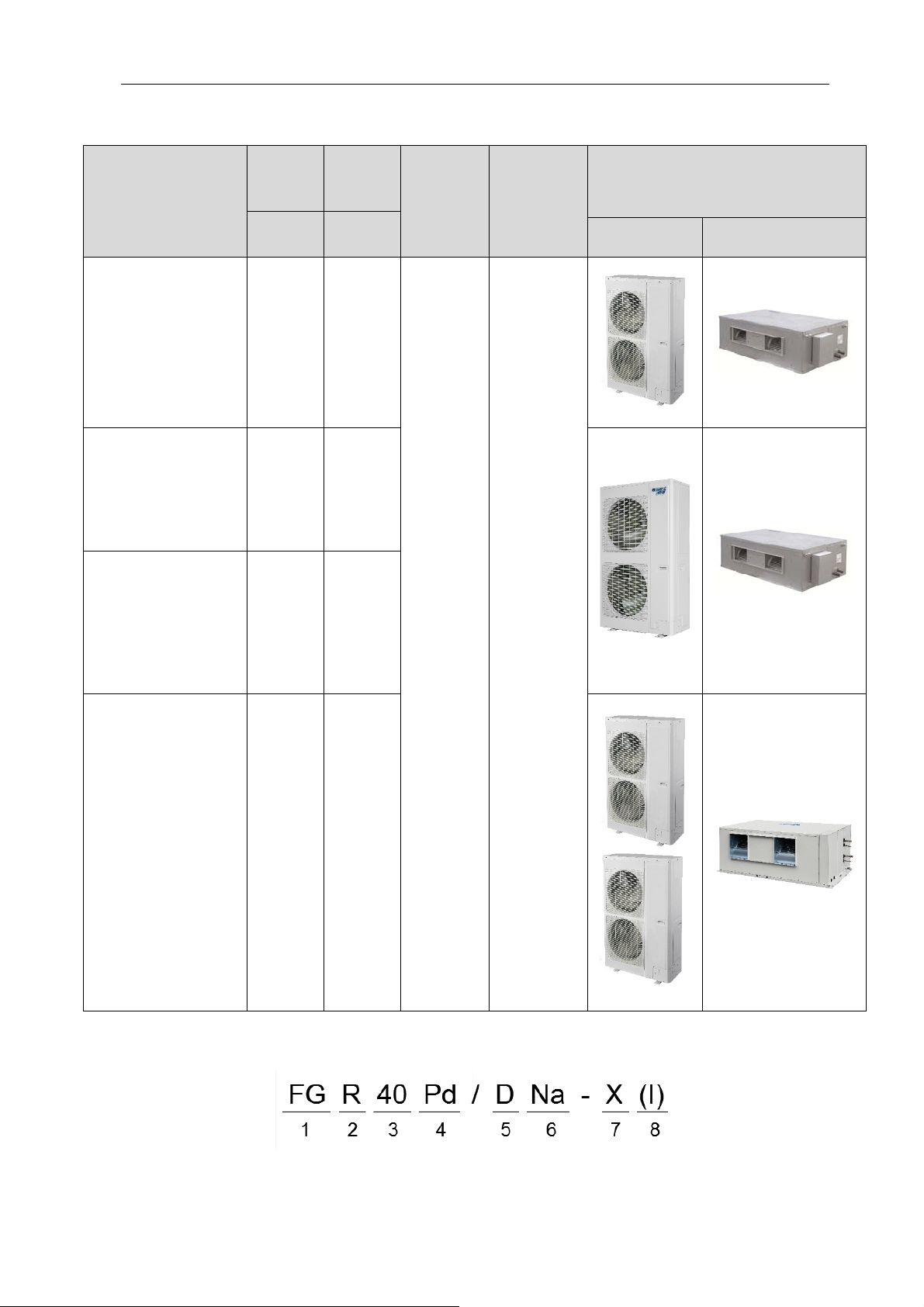
1 Product List
Cooling
Capacity
Model
kW kW
FGR20Pd/DNa-X 20 22
FGR25Pd/DNa-X 25 27.5
FGR30Pd/DNa-X 30 33
Heating
Capacity
3N/380-41
5V/50Hz/
Power
Supply
60Hz
Refrigerant
R410a
Appearance
Outdoor Indoor
FGR40Pd/D(2)Na-X 40 43
2 Nomenclature
2
Page 5
Duct type split Air conditioner Inverter Series
NO. Description Options
1 Ducted Type Air Conditioner -
Cooling only type-omitted
2 Unit type
Auxiliary hot water plate and pipe type-W
3 Cooling capacity Nominal cooling capacity (kW)
Heat pump
4 Frequency conversion system
5 Design No. Arranged based on A, B, C, D,and so on
6 Refrigerant
Others to be applied for when they are used
7 Power type
(The unit to be exported must be expressed)
8 Indoor and outdoor unit code
Fixed frequency-omitted
Frequency conversion-Pd
R22-omitted
R407-N
R410a-Na
380-415V 3Ph~,50/60Hz-X
Outdoor unit-(O)
Indoor unit-(I)
The entire unit is not expressed.
3 Specifications
Model Heat pump FGR20Pd/DNa-X FGR25Pd/DNa-X
Capacity
Power input
Current input
Indoor unit
Outdoor unit
Connection
pipe
Loading
quantity
EER/COP W/W 2.55/3.25 2.65/3.10
Power supply Ph/V/Hz 3N/380-415/(50/60) 3N/380-415/(50/60)
Refrigerant charge volume kg 6.4 8.0
Dimension
(W×D×H)
Net Weight/Gross weight kg 82/104 99/134
Dimension
(W×D×H)
Net Weight/Gross weight kg
diameter
Max. distance
Cooling kW 20 25
Heating kW 22 27.5
Cooling kW 7.8 9.4
Heating kW 6.8 8.9
Cooling A 16.5 18.9
Heating A 14.4 17.2
Airflow volume
ESP
Sound pressure level dB(A) 52 53
Sound pressure level dB(A) 62 63
Outer
20'GP/40'GP/40'HQ set 12/24/24 10/20/22
Rated Pa 120 120
Range Pa 0-250 0-250
Outline mm 1460×790×365 1690×870×440
Package mm 1575×880×385 1785×985×450
Outline mm 940×320×1430 940×460×1615
Package mm 1020×420×1460 1020×560×1645
Liquid Inch(mm) Φ3/8 Φ3/8
Gas Inch(mm) Φ3/4 Φ7/8
Height mm 30 30
Length mm 50 50
CFM
m3/h
2178
3700
120/130
2472
4200
146/162
3
Page 6
Duct type split Air conditioner Inverter Series
Model Heat pump FGR30Pd/DNa-X FGR40Pd/D(2)Na-X
Capacity
EER/COP W/W 2.65/3.20 2.60/3.10
Power input
Current input
Refrigerant charge volume kg 9.5 6.4×2
Indoor unit
Outdoor unit
Cooling kW 30 40
Heating kW 33 43
Power supply Ph/V/Hz 3N/380-415/(50/60) 3N/380-415/(50/60)
Cooling kW 11.3 15.4
Heating kW 10.3 13.9
Cooling A 22.7 27.8
Heating A 20.7 26.4
Airflow volume
ESP
Sound pressure level dB(A) 55 56
Dimension
(W×D×H)
Net Weight/Gross weight kg 105/145
Sound pressure level dB(A) 65 66
Dimension
(W×D×H)
Net Weight/Gross weight kg 175/190
Rated Pa 120 120
Range Pa 0-250 0-250
Outline mm 1690×870×440 1680X900X650
Package mm 1785×985×450 1800X1020X670
Outline mm 940×460×1615 940×320×1430
Package mm 1020×560×1645 1020×420×1460
CFM 3060 4120
m3/h 5200 7000
165/210
(120/130) X2
Outer
Connection
pipe
Loading
quantity
Note:
Specifications may be changed due to product improvement. Please refer to nameplates of the units.
◆
Noise data are collected from a semi-anechoic room. Decibels may be slightly higher in actual operation due to
◆
environmental change.
Above parameters are tested under the condition:high fan speed
◆
Cooling : Indoor air temperature 27°C DB/19°C WB, Outdoor air temperature 35°C DB/24°C WB;
◆
Heating : Indoor air temperature 20°C DB/15°C WB, Outdoor air temperature 7°C DB/6°C WB.
◆
diameter
Max.
distance
20'GP/40'GP/40'HQ set 10/20/22 7/18/18
Liquid Inch(mm) Φ1/2 Φ3/8
Gas Inch(mm) Φ1 Φ3/4
Height mm 30 30
Length mm 50 50
4
Page 7

Duct type split Air conditioner Inverter Series
CONTROL
5
Page 8
Duct type split Air conditioner Inverter Series
1 Wired Controller
1.1 Control panel
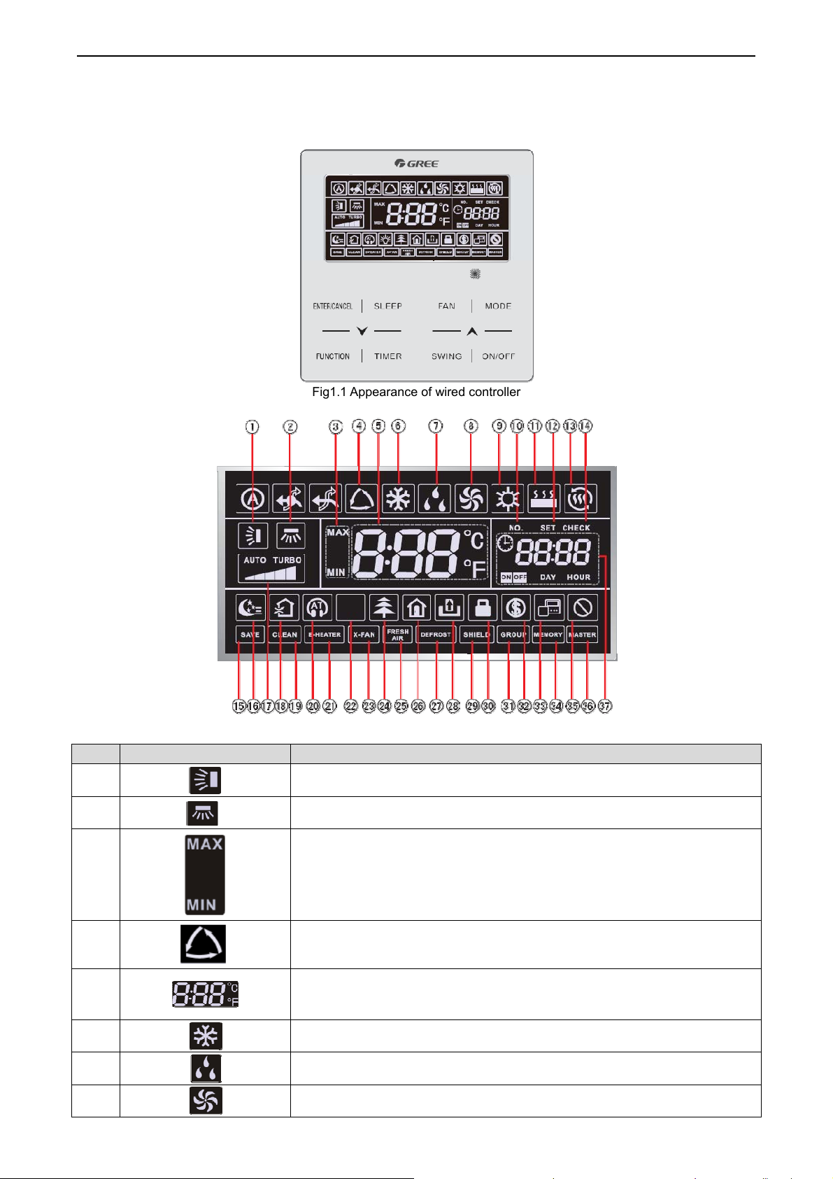
Fig1.1 Appearance of wired controller
Fig1.2 LED graphics of wired controller
Table 1.1 LED display instruction
No. Symbols Instructions
1
Up and down swing function
2
3
4
5
6
7
8
*
*
Left and right swing function
It's valid under Save mode and displays during setting process.
Temperature lower limit for Cooling: Limit the minimum temperature value
under Cooling or Dry mode.
Temperature upper limit for Heating: Limit the maximum temperature value
under Heating, Space Heating or 3D Heating
mode.
Auto mode (Under Auto mode, the indoor units will automatically select their
operating mode as per the temperature
change so as to make the ambient comfortable.)
It shows the setting temperature value(In case the wired controller is controlling
a Fresh Air Indoor Unit, then the
temperature zone will display FAP)
Cooling mode
Dry mode
Fan mode
6
Page 9
Duct type split Air conditioner Inverter Series
No. Symbols Instructions
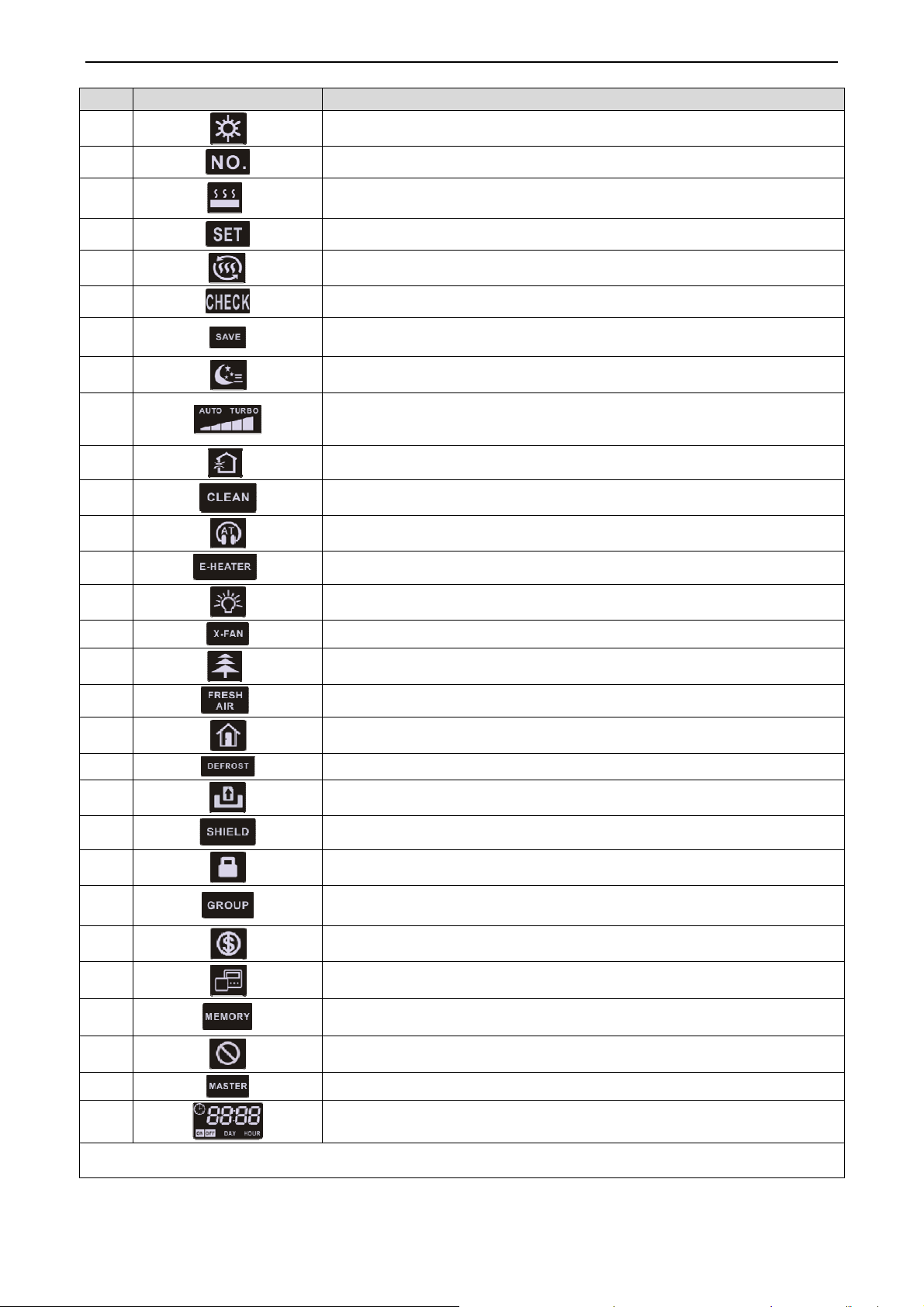
9
10
11
12
13
14
15
16
17
18
19
20
21
*
-*
*
*
Heating mode
When inquiring or setting project number of indoor unit, it displays "NO." icon
Floor Heating mode (When Heating and Floor Heating simultaneously shows
up, it indicates 3D Heating is activated.)
Display "SET" icon under parameter setting interface
Space Heating mode
Display "CHECK" icon under parameter view interface
Outdoor unit operates under Save mode/upper limit of system capacitor less
100%/remote Save status
Sleep status
Current set fan speed (including auto, low speed, medium-low speed, medium
speed, medium-high speed, high speed
and turbo seven status)
Air status, Indoor unit optional function
Remind to clean the filter
Quiet status (including Quiet and Auto Quiet two status)
Allow auxiliary electric heating On icon
22
23
24
25
26
27
28
29
30
31
32
33
34
*
*
Light On/Off function
X-fan function
Health function, Indoor unit optional function
Reserved function
Out function
Outdoor unit defrosting status
Gate-control function
Shielding status
Child Lock status
One wired controller controls multiple indoor units
Save status of indoor unit
It indicates the current wired controller is the slave wired controller (address of
wired controller is 02)
Memory status (The indoor unit resumes the original setting state after power
failure and then power recovery)
35
36
37
Note: When wired controller is connected with different indoor units, some functions will be different
Invalid operation
Current wired controller connects master indoor unit
Timer zone:Display system clock and timer status
1.2 Installation and removal
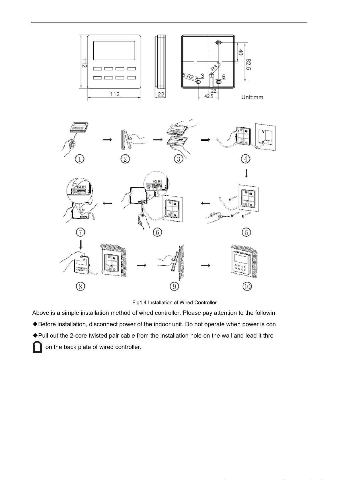
1.2.1 Installation dimensions
7
Page 10
Duct type split Air conditioner Inverter Series
1.2.2 Installation method
Fig1.3 Installation dimensions
Fig1.4 Installation of Wired Controller
Above is a simple installation method of wired controller. Please pay attention to the following:
Before installation, disconnect power of the indoor unit. Do not operate when power is connected.
◆
Pull out the 2-core twisted pair cable from the installation hole on the wall and lead it through the hole
◆
on the back plate of wired controller.
Place the wired controller on wall and secure its back plate on
◆
ect the 2-core twisted pair cable to terminal H1 and termi
Conn
◆
Stick the cable in the slot that is left of the terminals and buc
◆
back plate.
Note:
If
caliber of the communication cord is too large, which causes difficulty in leading or sticking the cord
according to above point 2 and point 5, strip some of the sheath of the communication cable to meet the
installation requirement.
wall with screw M4X25.
nal H2. Tighten up the screws.
kle the wired
controller’s panel with its
1.2.3 Removal method
8
Page 11
Duct type split Air conditioner Inverter Series
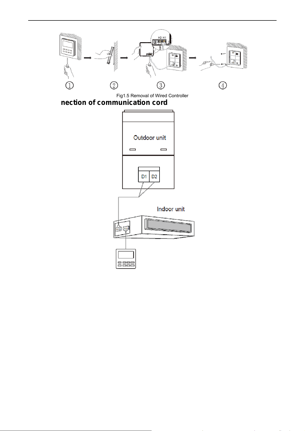
Fig1.5 Removal of Wired Controller
1.2.4 Connection of communication cord
Fig1.6 One wired controller controls one indoor unit
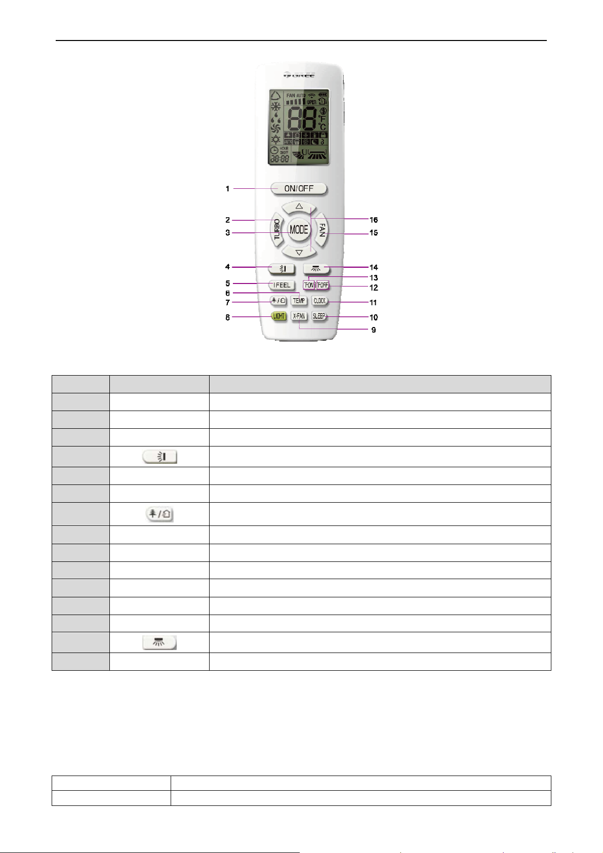
2 Remote Controller YAP1F
9
Page 12
Duct type split Air conditioner Inverter Series
Button name and function introduction
No. Button name Function
1 ON/OFF Turn on or turn off the unit
2 TURBO Set turbo function
3 MODE Set operation mode
4 Set up&down swing status
5 I FEEL Set I FEEL function
6 TEMP Switch temperature displaying type on the unit’s display
7 Set health function and air function
8 LIGHT Set light function
9 X-FAN Set X-FAN function
10 SLEEP Set sleep function
11 CLOCK Set clock of the system
12 TOFF Set timer off function
13 TON Set timer on function
14 Set left&right swing status
15 FAN Set fan speed
3 Introduction to IDU Functions
Indoor unit functions cover user operation functions and engineering application functions. For user
operation functions, refer to wired controller and remote controller.
Engineering application functions include:
SN Function Name
1 User parameter query
10
Page 13
Duct type split Air conditioner Inverter Series
2 User parameter settings
3 Engineering parameter query
4 Engineering parameter settings
Engineering application functions can be operated through the IDU wired controller(XK46).
3.1 User Parameter Query
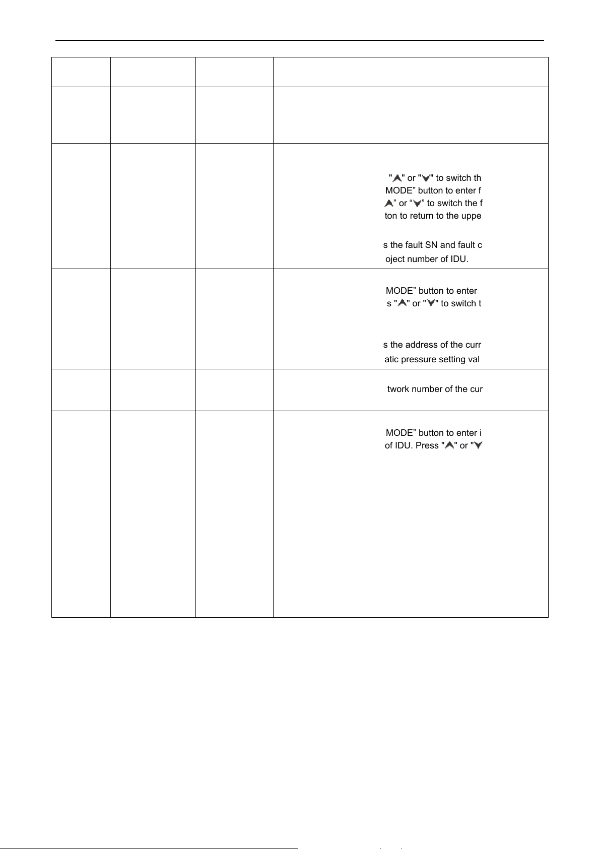
User parameters can be queried in power-on or power-off status.
(1) Press and hold the “FUNCTION” button for five seconds to enter the user parameter query interface.
The temperature area displays “C00” and “V
Select a parameter code by pressing “ ” or “ ”
(2)
Press the “ENTER/CANCEL” button to return to the upper-level menu till quitting parameter query.
(3)
iew” is on.
.
The user parameter query list is as follows:
Parameter
Code
C00
C06
C07
C08
C09
C12
C17
Parameter Name
Parameter
setting ingress
Preferential
operation query
Indoor
environment
temperature
query
Prompt time
query for air filter
cleaning
Wired controller
adress query
Outdoor
environment
temperature
query
Indoor relative
humidity query
Parameter
Range
Display mode:
Timer area: displays the project numbe
-
00: common
operation
01:
preferential
operation
-9 to 99
4-416: days Timer area: displays the prompt time for air filter cleaning.
01, 02
-9 to 99
20-90
current IDU.
Note: If the current HBS network consists of multiple
IDUs, only the IDU that has the minimum project
number is displayed.
Operation method:
In “C06” status, press the “MODE” button to enter the
preferential operation query interface. Press “ ” or “ ” to
switch the IDU SN.
Display mode:
Temperature area: displays the project number of the
current IDU.
Timer area: displays the preferential operation setting
value of the current IDU.
Operation me
In “C07” status, press the “MODE” button to enter the
indoor environment temperature query interface. Press "
" or " " to switch the IDU SN.
Display mode:
Temperature area: displays the project number of the
current IDU.
Timer area: displays the temperature value of the indoor
environment temperature sensor after replenishment.
Timer area: displays the adress of the current wired
controller.
Timer area: displays the temperature value of the
environment temperature sensor of the master ODU.
Operation method:
In “C17” status, press the “MODE” button to enter the
indoor relative humidity query interface. Press “▲” or “▼”
to switch the IDU SN.
Display mode:
Temperature area: displays the relative humidity value.
Timer area: displays the project number of IDU (project
numberes are arranged from small to large).
If the HBS network consists of only one IDU, the timer
area directly displays the IDU relative humidity value in
the “C17” interface.
thod:
View Method
r of the
11
Page 14
Duct type split Air conditioner Inverter Series
Note:
In parameter query status, "FAN", “TIMER”, "SLEEP", and "SWING" are invalid. By pressing the
“ON/OFF” button, users can return to the main interface but not power on/off the unit.
3.2 User Parameter Settings
User parameters can be set in power-on or power-off status.
(1) Press and hold the “FUNCTION” button for five seconds. The temperature area displays “C00”.
Press and hold the “FUNCTION” button for another five seconds to enter the wired controller
parameter setting interface. The temperature area
displays “P00”.
(2) Select a parameter code by pressing “ ” or “ ”. Press the “MODE” button to switch to parameter
value settings. The parameter value blinks. Adjust the parameter value by pressing “ ” or “ ” and
then press the “ENTER/CANCEL”
(3)
Press the “ENTER/CANCEL” button to return to the upper-level menu till quitting parameter
button to complete settings.
settings.
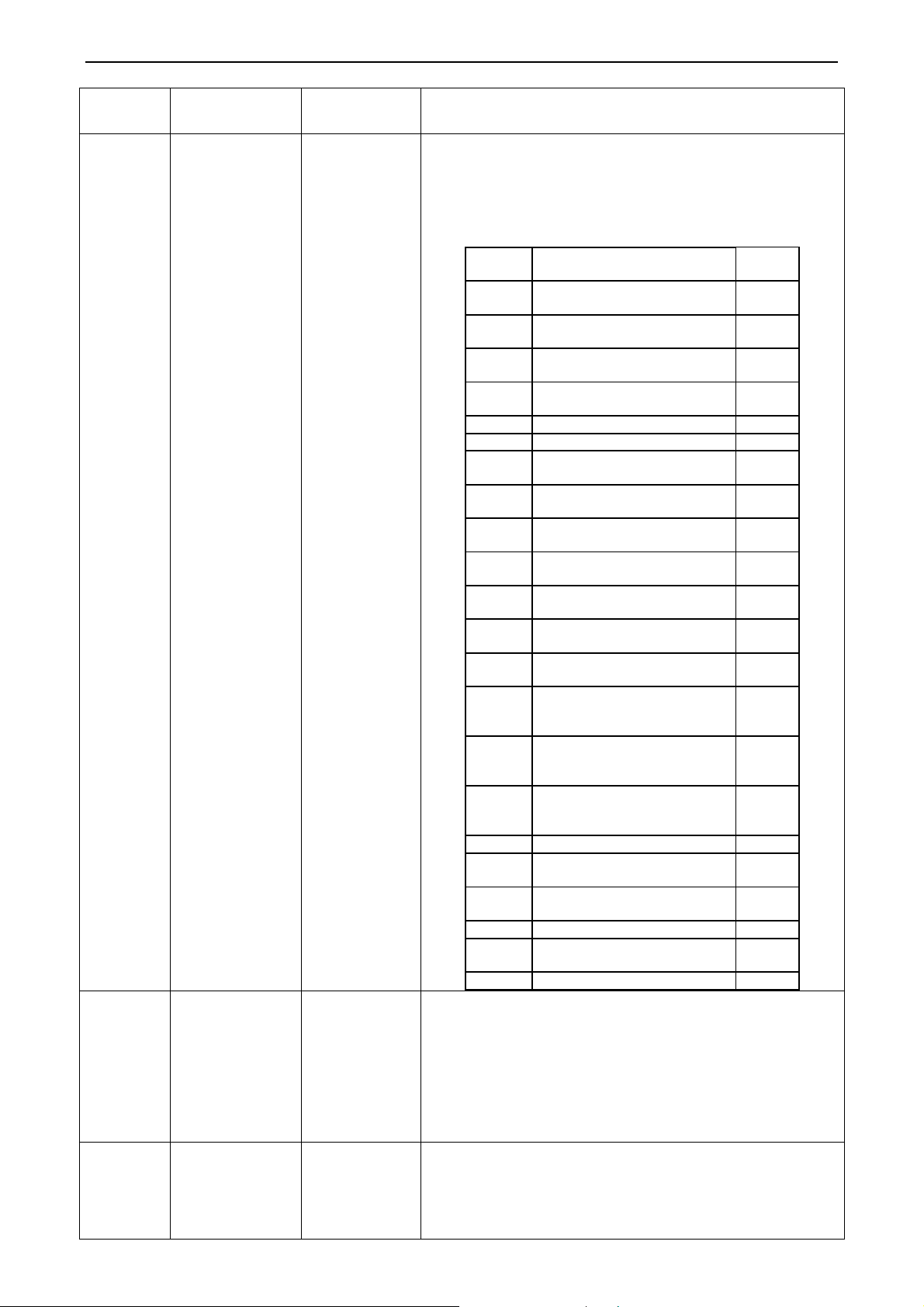
(4) The user parameter setting list is as
Parameter
Code
P10
P11
P13
P30
Parameter
Name
Master IDU
settings
Infrared
connection
settings of
wired controller
Wired controller
address
settings
Static pressure
settings for
indoor fan
Parameter Range
00: does not change the
master/slave status of the
01: sets the current IDU
01: master wired
02: slave wired controller
Type 1: 03.04.05.06.07
01.02.03.04.05.06.07.08.
follows:
current IDU
to master IDU
00: disabled
01: enabled
controller
Type 2:
09
Default
Val ue
00
01
01
05
Remark
After the IDU connected
with the current wired controller is
successfully set to master IDU, "MASTER"
on the wired controller is on.
This setting can only be enabled through the
master wired controller.
When the infrared remote receiving function
of the wired controller is disabled, neither the
master nor slave wired controller can receive
remote signals. The wired controllers can
only be operated by pressing.
When two wired controllers simultaneously
control one IDU, the two wired controllers
should use different addresses. The slave
wired controller (address: 02) does not have
the unit parameter setting function except its
own address settings.
After identifying the IDU type, the wired
controller only displays the available
static pressure levels.
The static pressure levels fall into
1)
levels
and nine levels for VRF IDUs. T
w
ired controller only displays t
pressur
identified IDU t
2) W
w
levels, the
adj
accord
princi
receiv
control
monitori
rang
3)Duri
setting val
e levels matched with t
ype.
hen the HBS network co
ith both five and nine static pr
wired controller displays ni
ustable static pressure leve
ing to the maximum co
ple. If the static pressure
ed by the IDU from the wi
ler, remote controller
ng system exceed the
e, the limit value prevai
ng power-on and synchroniza
ue of static pressure
five
he
he static
he
nsists of IDUs
essure
ne
ls
ntrol
levels
red
, or remote
setting
ls.
tion, the
levels is
12
Page 15
Duct type split Air conditioner Inverter Series
Parameter
Code
P31
P33
P34
P37
P38
P43
P46
Parameter
Name
High-ceiling
installation
Timer function
settings
Repeating
validity for
time-point
timing
Cooling setting
temperature in
automatic mode
Heating setting
temperature in
automatic mode
Preferential
operation
settings
Accumulated
time clearing for
air filter
cleaning
Parameter Range
00: standard-ceiling
installation height
01: high-ceiling
installation height
00: common timing
01: time-point timing
00: single timing
01: repeated everyday
17°C -30°C 25
16°C -29°C 20
00: common operation
01: preferential operation
00: not cleared
01: cleared
Default
Val ue
00
00
00
00
00
Remark
determined by settings of the IDU.
This setting is valid only when the timer
function is set to time-point timing.
Cooling setting temperature – heating setting
temperature ≥ 1.
Note: The two settings are still valid in
remote shielding status.
When power supply is insufficient, users are
allowed to power on/off the IDU set with
preferential operation and other IDUs are
forcibly powered off. A fault code is displayed
on the IDU that is forcibly powered off.
Note:
In parameter setting status, "FAN", “TIMER”, "SLEEP", and "SWING" are invalid. By pressing the
“ON/OFF” button, users can return to the main interface but not power on/off the unit.
3.3 Engineering Parameter Query
Engineering parameters can be queried in power-on or power-off status.
Press and hold the “FUNCTION” button for five seconds to enter the engineering parameter query
interface. The temperature area displays “C00” and “View” is on.
(1) Within five seconds after “C00” is displayed, continuously press the “MODE” button for three times in
an interval less than one second to enter engineering parameter query.
(2) Select a parameter code by pressing “ ” or “ ”
Press the “ENTER/CANCEL” button to return to the upper-level menu till quitting parameter query.
(3)
In the engineering parameter query interface, users can also query user parameters listed in Table 3.1.
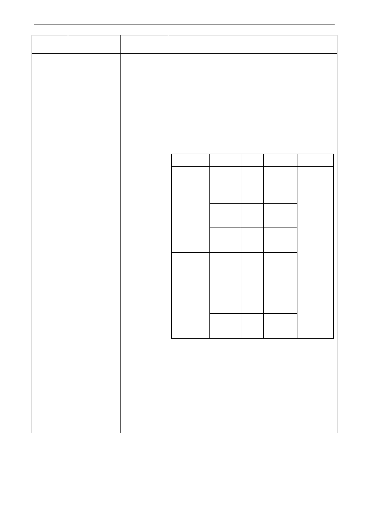
The engineering parameter query list is as
Parameter
Code
C00
C02
Parameter Name
Parameter setting
ingress (default)
Indoor unit
capacity query
Parameter
Range
follows:
-
-
.
View Method
Display mode:
Timer area: displays the project number of the current IDU.
Note: If the current HBS network consists of multiple IDUs, only
the IDU that has the minimum project number is displayed.
Operation method:
In “C02” status, press the “MODE” button to enter the preferential
operation query interface. Press " " or " " to switch the project
number of IDU.
13
Page 16
Duct type split Air conditioner Inverter Series
Parameter
Code
C05
C10
C13
C14
Parameter Name
Historical fault
query ingress of
IDU
Static pressure
setting query of
ODU
Outdoor unit
network number
query
Temperature
query for
inlet-tube
temperature
sensor of IDU
Parameter
Range
Display mode:
Temperature area: displays the project number of the current IDU.
Timer area: displays the current IDU capacity/IDU capacity after
adjustment.
Operation method:
1. In “C05” status, press the “MO
fault quer
Five historical
faults
00: 0 Pa
20: 20 Pa
50: 50 Pa
82: 82 Pa
1-255 Timer area: displays the network number of the current ODU.
-9 to 99
numb
of the current IDU. Press “
the “ENTER/CANCEL” button to return to the upper-level menu.
Display mode:
Temperature area: displays the fault SN and fault code.
Timer area: displays the project number of IDU.
Operation method:
In “C10” status, press the “MODE” button to enter static pressure
setting query of ODU. Press " " or " " to switch the ODU
address.
Display mode:
Temperature area: displays the address of the current ODU.
Timer area: displays the static pressure setting value.
O
peration method:
In “C14” status, press the “MODE” button to enter inlet-tube
temperature sensor query of IDU. Press " " or " " to switch the
IDU SN.
Display mode:
Temperature area: displays the project number of the current IDU.
Timer area: displays the temperature value.
If the HBS network consists of only one IDU, the timer area
directly displays the temperature value in the “C14” interface.
No matter Fahrenheit or Centigrade remote signals are received,
the temperature is displayed in Centigrade.
When the wired controller displays the inlet-tube temperature after
receiving signals from the remote controller, the inlet-tube
temperature of the IDU that has the minimum project number in the
HBS network is displayed by default.
y interface. Press " " or " " to switch the proj
er of IDU. Press the “MODE” button to enter fault code quer
View Method
DE” button to enter the hist
” or “ ” to switch th
e fault SN. Press
orical
ect
y
14
Page 17

Duct type split Air conditioner Inverter Series
Parameter
Code
C15
C16
n2
Parameter Name
Temperature
query for outlet
temperature
sensor of IDU
Opening degrees
query of electronic
expansion valve
of IDU
Capacity
configuration ratio
upper-limit of
outdoor/IDU
Parameter
Range
-9 to 99
0-20
35: 135%
50: 150%
View Method
O
peration method:
In “C15” status, press the “MODE” button to enter outlet
temperature sensor query of IDU. Press " " or " " to switch the
IDU SN.
Display mode:
Temperature area: displays the project number of the current IDU.
Timer area: displays the temperature value.
If the HBS network consists of only one IDU, the timer area
directly displays the temperature value in the "C14" interface.
No matter Fahrenheit or Centigrade remote signals are received,
the temperature is displayed in Centigrade.
When the wired controller displays the inlet-tube temperature after
receiving signals from the remote controller, the inlet-tube
temperature of the IDU that has the minimum project number in the
HBS network is displayed by default.
Operation method:
In “C16” status, press the “MODE” button to enter electronic
expansion valve opening degree query of IDU. Press " " or " "
to switch the IDU SN.
Display mode:
Temperature area: displays the project number of the current IDU.
Timer area: displays the opening degree value.
If the HBS network consists of only one IDU, the timer area
directly displays the opening degree value of electronic expansion
valve in the “C16” interface.
When the wired controller displays the opening degree of
electronic expansion valve after receiving signals from the remote
controller, the opening degree of electronic expansion valve of the
IDU that has the minimum project number in the HBS network is
displayed by default.
Temperature area: displays the parameter code.
Timer area: displays the setting value of capacity configuration
ratio of the current outdoor/IDU.
n6
n7
Historical fault
query ingress of
ODU
Parameter query
ingress of ODU
Five historical
faults
01-13
25-29
Operation method:
In “n6” status, press the “MODE” button to enter fault code query
of ODU (when a wired controller controls multiple IDUs, only the
faults memorized by the IDU that has the minimum project number
can be queried). Press “ ” or “ ” to switch the fault SN. Press
the “ENTER/CANCEL” button to return to the upper-level menu.
Display mode:
Temperature area: displays the fault SN and fault code from left to
right (1-5, faults are arranged from the earliest to the latest).
Timer area: displays the project number of the ODU.
Operation method (n7 query is not supported for the slave wired
controller):
In “n7” status, the timer area is not displayed. Press the “MODE”
button to enter parameter query of ODU. The first bit in the
temperature area (display bit of the ODU module ID) blinks. Press
“▲” or “▼” to switch the ODU module ID. Press the “MODE”
button to select an ODU module. In this case, the first bit in the
temperature area stops blinking, and the second and third bits in
the temperature area display the parameter code. The timer area
15
Page 18
Duct type split Air conditioner Inverter Series
Parameter
Code
A6
nb
Parameter Name
Unit
cooling/heating
function
Bar code query of
IDU
Parameter
Range
nA:
cooling/heating
nC:
single-cooling
nH:
single-heating
nF: air supply
0-9, A-Z, a-z, -
View Method
displays a corresponding parameter value. Press “▲” or “▼” to
switch the parameter code and press the “ENTER/CANCEL”
button to return to the upper-level menu.
Display mode:
Temperature area: displays the ODU module ID and parameter
code from left to right.
Timer area: displays a corresponding parameter value to the right.
Parameter
Code
01
02
03
04
05 Module high-pressure °C
06 Module low-pressure °C
07
08
09
10
11
12
13
25
(Actual value = Displayed value *
26
(Actual value = Displayed value *
27
(Actual value = Displayed value *
28 Defrosting temperature °C
29
30
31 Oil return temperature °C
32
33 Outlet temperature of condenser °C
Temperature area: displays the parameter code.
Timer area: displays the cooling/heating function setting value of
the current unit.
Operation method (nb query is not supported for the slave wired
controller):
In “nb” status, the timer area is not displayed. Press the “MODE”
button to enter bar code query. The temperature area displays
“nb” and the project number in the timer area blinks. Press “▲” or
Parameter Name Unit
Outdoor environment
temperature
Operation frequency of
compressor 1
Operation frequency of
compressor 2
Operation frequency of outdoor
fan
Discharge temperature of
compressor 1
Discharge temperature of
compressor 2
Discharge temperature of
compressor 3
Discharge temperature of
compressor 4
Discharge temperature of
compressor 5
Discharge temperature of
compressor 6
Operation frequency of
compressor 3
Outdoor unit heating EXV1
10)
Outdoor unit heating EXV2
10)
Subcooler EXV
10)
Liquid-extracting temperature of
subcooler
Outlet temperature of
accumulator
Inlet-tube temperature of
condenser
°C
Hz
Hz
Hz
°C
°C
°C
°C
°C
°C
Hz
PLS
PLS
PLS
°C
°C
°C
16
Page 19
Duct type split Air conditioner Inverter Series
Parameter
Code
Parameter Name
Parameter
Range
View Method
“▼” to switch the project number of IDU.
Press the “MODE” button to select an IDU. The temperature area
displays “Un” and the timer area displays “-n”. Press “▲” or “▼” to
display the entire-unit bar code and controller bar code of IDU.
Press the “ENTER/CANCEL” button to return to the upper-level
menu. The temperature area displays “nb” and the timer area
displays the project number of the queried IDU. Press the
“ENTER/CANCEL” button again to return to the upper-level menu.
Display mode:
Temperature area: displays nb/Un/Pc/bar code.
Timer area: displays -n/project number/bar code.
The following is an example:
Example
Entire-init bar
code of IDU
N1r0128150066
Controller bar
code of IDU
N1r0128150067
Temperature
Area
Un (to the
right)
N1r 0128
150 066
Pc -n
N1r 0128
150 067
Timer
Area
-n
(in the
middle)
Remark 1 Remark 2
indicates
It
that the
following is
the entire-unit
bar code of
IDU.
indicates
It
the former
seven bits of
the bar code.
indicates
It
the latter six
bits of the bar
code.
It
indicates
that the
following is
the controller
bar code of
IDU.
indicates
It
the former
seven bits of
the bar code.
It
indicates
the latter six
bits of the bar
code.
Press “▼” to
display
downward and
press “▲” to
display
upward.
Note:
1. Un indicates the entire-unit bar code of IDU and Pc indicates
the controller bar code of IDU.
2. When there is only one IDU, press the “MODE” button in “nb”
status to enter bar code query without selecting the project
number of IDU.
3. The system quits the query status if no operations are
performed in 60 seconds.
4. The bar code query starts from the entire-unit bar code of IDU
and ends at the controller bar code of IDU without circulation. That
is, the query does not start again even if users press “▼”.
Note:
In parameter query status, "FAN", “TIMER”, "SLEEP", and "SWING" are invalid. By pressing the
“ON/OFF” button, users can return to the main interface but not power on/off the unit.
3.4 Engineering Parameter Settings
Engineering parameters can be set in power-on or power-off status.
17
Page 20
Duct type split Air conditioner Inverter Series
(1) Press and hold the “FUNCTION” button for five seconds. The temperature area displays “C00”.
Continuously press the “MODE” button for
“FUNCTION” button for
temperature
Select a parameter code by pressing “ ” or “ ”. Press the “MODE” button to switch to parameter
(2)
area displa
five seconds to enter the engineering paramete
ys “P00”.
three times, and then press and hold the
r setting interface. The
value settings. The parameter value blinks. Adjust the parameter value by pressing “ ” or “ ” and
then press the “ENTER/CANCEL”
(3)
Press the “ENTER/CANCEL” button to return to the upper-level menu till quitting parameter
button to complete settings.
settings.
In the engineering parameter setting interface, users can also set user parameters. The engineerin
paramete
Parameter
r setting list is as follows:
Code
P15
P17
P20
P21
P22
P32
Parameter Name Parameter Range Default Value Remark
Power-down
memory mode
Historical fault
clearing for IDU
Environment
temperature
sensor settings
for IDU
Corrected value
of environment
temperature
sensor of IDU (for
cooling,
dehumidifying,
and air supply)
Corrected value
of environment
temperature
sensor of IDU (for
heating, fast
heating, and air
warming)
Capacity
00: standby after
power-down recovery
01: restoring the original
status after power-down
recovery
00: not cleared
01: cleared
01: temperature sensor
of air return vent
02: temperature sensor
of wired controller
03: temperature sensor
of air return vent for
cooling, dehumidifying,
and air supply;
temperature sensor of
wired controller for
heating
04: temperature sensor
of wired controller for
cooling, dehumidifying,
and air supply;
temperature sensor of
air return vent for
heating
-15 to +15
-15 to +15
-40% to +40% 00
00 --
Historical faults of all IDUs controlled
00
03
Temperature
sensor of unit:
0°C; temperature
sensor of wired
controller: 0°C
Temperature
sensor of unit:
-2°C;
temperature
sensor of wired
controller: 0°C
by the current wired controller are
cleared.
When there are master and slave
wired controllers and the
temperature sensor of wired
controller is used, only the
temperature sensor of the master
wired controller is used by default.
Note:
1) In automatic mode, the
envir
settings are invalid for a common
IDU but the setting value is
memorized.
2)The environment temperat
sensor settin
fresh-air IDU.
sensor of air return vent is used by
defau
Press “ ” or “ ” to add or reduce
by 1°C.
Press ” ” or ” ” to add or reduce
by 1°C.
The temperature sensor of unit and
the temperature sensor of wired
controller share the same corrected
value.
In heating mode, corrected value of
temperature sensor of unit =
corrected value of temperature
sensor of wired controller - 2°C.
Press " " or " " to add or reduce
onment temperature sensor
gs are invalid for
The temperature
lt.
g
ure
a
18
Page 21
Duct type split Air conditioner Inverter Series
Parameter
Code
P35
P36
P40
P52
Parameter Name Parameter Range Default Value Remark
adjustment
function of IDU
Factory setting
recovery for user
functions
Factory setting
recovery for
engineering
settings
Prevention for
heat collection
Setting of indoor
rotate speed in
efficiency testing
mode
00: invalid
01: valid
00: invalid
01: valid
00: disabled
10: 10 seconds
20: 20 seconds
30: 30 seconds
40: 40 seconds
50: 50 seconds
60: 60 seconds
100~1800
00
00
00
by 10%.
Select "01" and then press and hold
the “ENTER/CANCEL” button to
restore the factory settings for user
functions (factory setting recovery
fails if remote shielding is valid).
Select "01" and then press and hold
the “ENTER/CANCEL” button to
restore the factory status for
engineering settings (factory setting
recovery fails if remote shielding is
valid).
It indicates the number of seconds
for enabling the low-level fan every
15 minutes.
In P52, timer area show the actual
rotate speed of AHRI indoor fan
motor. Quick press “MODE”, enter
into setting interface, timer area
show the rotate speed of indoor fan
motor and twinkle, press “▲”
and”▼” to select the rotate speed,
Press “Mode” and hold for
0~5s, the rotate speed of indoor fan
motor will increase or decrease by
single digits; Press “MODE” and
hold for 5~10s, the rotate speed of
indoor fan motor will increase or
decrease by ten digits, within its
maximum and minimum value
(100~1800). Quick press
“Confirm/Cancel” to confirm and
return to last status,
P67
n0
n1
n3
n4
A7
Select the way of
adjusting static
pressure
System
conservation
operation settings
Defrosting period
settings
Forcible
defrosting
Highest capacity
output limitation
settings for ODU
Silent function of
ODU
00: manually
01:automatically
00: comfortability
preferred
01: conservation
preferred
40: 40 minutes
50: 50 minutes
60: 60 minutes
00: common
01: forcible defrosting
08: 80%
09: 90%
10: 100%
00: no silent function
01-09: intelligent
00
00
50
-
10
00
Present Way:
Temperature area: P52
Timer arer: Indoor fan motor rotate
speed.
-
After settings, it automatically
restores to "00".
Enter query in “n4” status. The
temperature area displays the
function code and the timer area
displays the corresponding function
setting value.
Enter query in “A7" status. The
temperature area displays the
function code and the timer area
19
Page 22
Duct type split Air conditioner Inverter Series
Parameter
Code
Note:
In parameter setting status, "FAN", “TIMER”, "SLEEP", and "SWING" are invalid. By pressing the
“ON/OFF” button, users can return to the main interface but not power on/off the unit.
Parameter Name Parameter Range Default Value Remark
nighttime silent mode
10-12: forcible silent
mode
displays the corresponding function
setting value.
3.5 Failure Display
When a fault occurs during the system operation, the temperature area of wired controller displays
the fault code. When multiple faults occur, fault codes are circularly displayed.
When a fault occurs, power off the unit and ask for professional maintenance personnel for help.
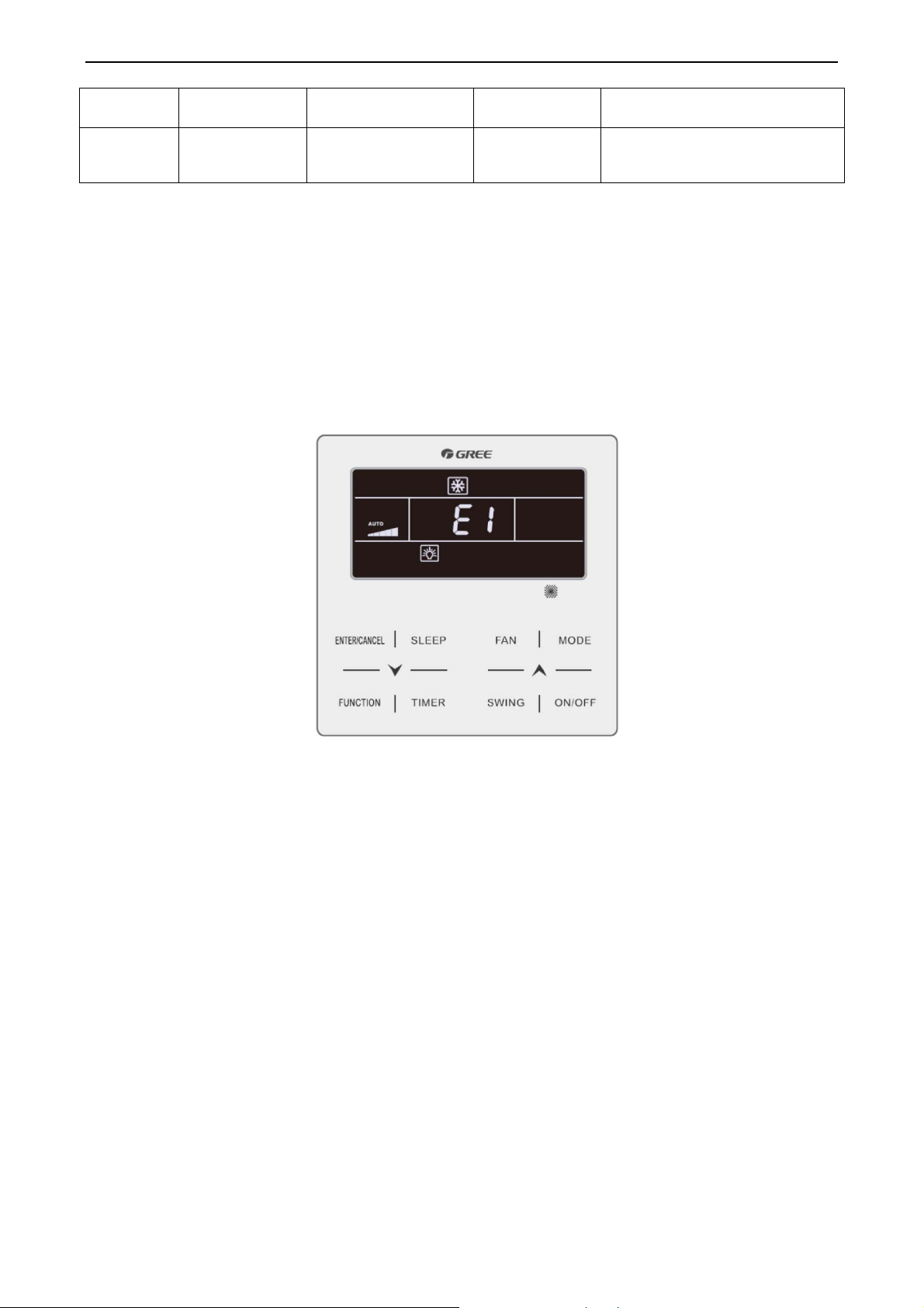
The following figure shows the power-on high-pressure protection fault interface.
Power-on High-pressure Protection Fault Interface
4 Monitoring Software
4.1 Function introduction
Integrating with telecommunication technology and computing software, Gree Commissioning Tool
Kits can realize the comprehensive monitor, control and commissioning on central air conditioners. It is
an efficient solution for the management of central air conditioners that are separated in different parts of
a building. Administrator doesn’t need to control every unit on site, but rather controls the units by just
sitting in front of a computer. This will not only improve the productivity, but also reduce cost on human
resources, property and management.
Gree Commissioning Tool Kits can monitor and control the duct type split air conditioner inverter
series. User can monitor and control units by monitoring the computer. This software is an efficient tool
for the intelligent air conditioning management as well as installation and after-sales service and
commissioning. It can debug units and control units’ operation status quickly and conveniently. It will not
only improve the productivity but also reduce the difficulty and cost of commissioning and maintenance,
providing better and faster service to customers.
20
Page 23
Duct type split Air conditioner Inverter Series
4.2 Connection of computer and units
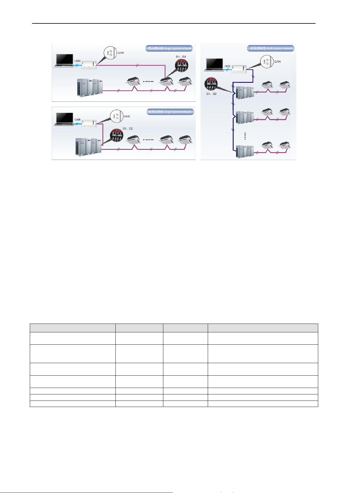
It can be connected with single-system network or multi-system network. In the single-system
network, indoor units or outdoor units are connectable, while in the multi-system network, only the
master outdoor unit can be connected.
Seen from the diagram, Gree commissioing network is made up of 3 parts:
The 1st part is the monitoring computer, including Gree debugger and Gree USB converter driver
that are installed in the computer.
The 2nd part is Gree USB converter, which is to convert the air conditioning communication into
computing communication. This part is made up of Gree USB data converter and USB data wire.
The 3rd part is air conditioners, including outdoor units, indoor units and the connection wires. If
connection wire is not long enough, it’s OK to connect via the patching board of the commissioning tool
kits. In a single-system network, both indoor units and outdoor units can be connected, while in a
multi-system network, only the master outdoor unit can be connected.
4.3 Parts introduction
4.3.1 List of parts
Name Model Material no. Remark
Gree USB data converter MC40-00/B 30118027
Gree Commissioning Tool Kits
(CD-ROM)
USB wire \ 40020082
Communicaiton board \ 30118015
Board connection wire (1m) \ 4001023229 4-core wire connecting units and converter
Board connection wire (5.5m) \ 4001023214 4-core wire connecting units and converter
Instruction manual \ 66174100018 Instruction manual
DG40-33/A(C) 36400000003
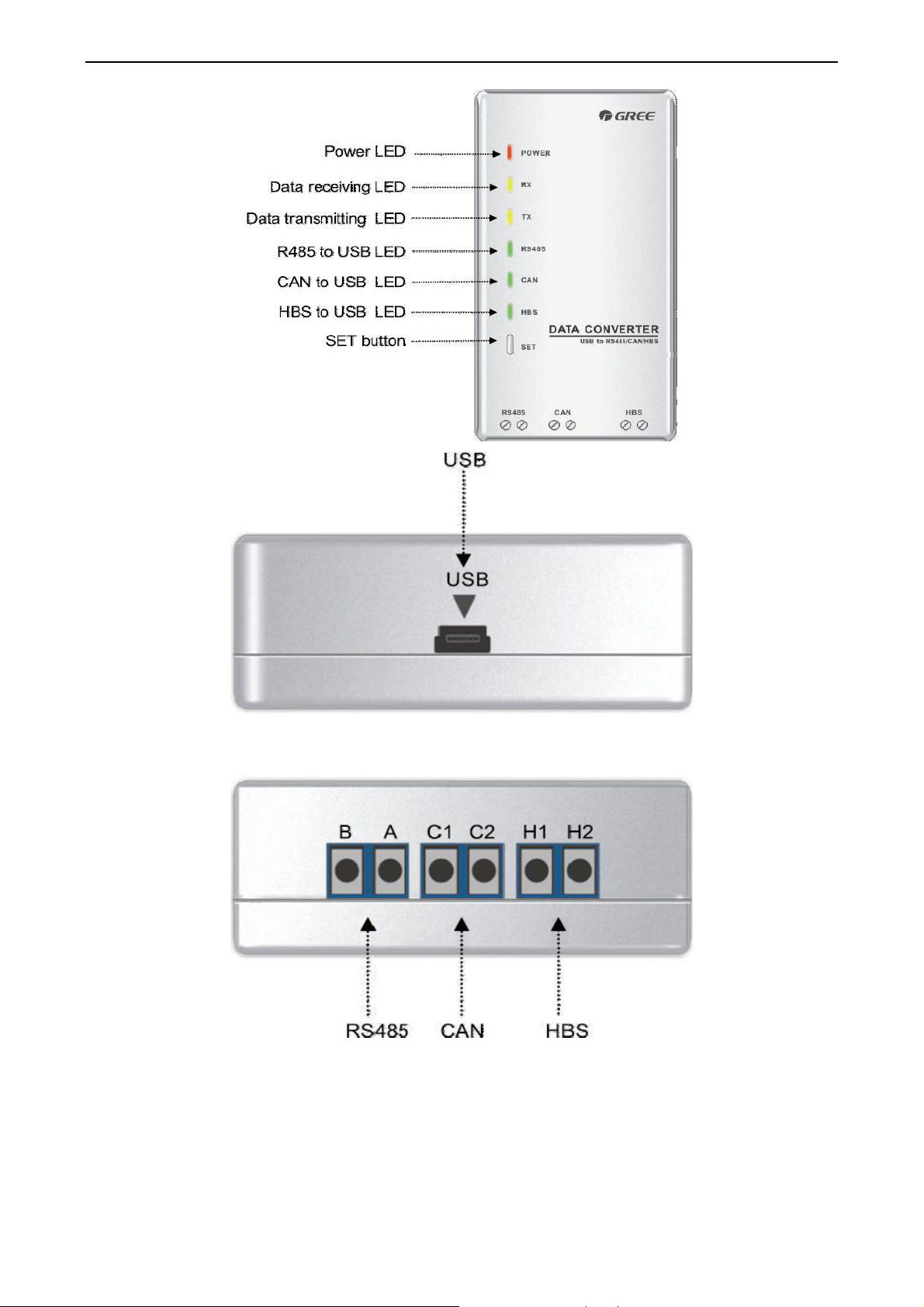
4.3.2 Gree USB data converter
4.3.2.1 Functions introduction
Convert the air conditioning communication
into computing communication
Include Gree debugger, monitoring software,
USB driver and USB converter configuring
software.
Wire connecting computer’s USB interface
and converter
This board can be used when units are far
from the computer.
Gree USB data converter will convert the RS485, HBS and CAN commucation within the air
conditioners into the communication that is recognizable by computer’s USB interface.
4.3.2.2 Appearance
21
Page 24
Duct type split Air conditioner Inverter Series
4.3.2.3 Operation instruction
Power LED: a red light. If the red light is on, it indicates normal power supply. If the red light is off,
it indicates the power supply of converter is not normal.
Communication LEDs: yellow lights. When converter is working and the computer is transmitting
data, the TX data transmitting light will be flickering. When units are uploading data to the
22
Page 25

Duct type split Air conditioner Inverter Series
computer, the RX data receiving light will be flickering.
When converter is under RS485 data transferring mode, the function LED
be on.
When converter is under CAN data transferring m
on.
When converter is under HBS data transferring mode, the function LED of HBS to USB will be
on.
USB interface: connect U
CAN interface: When converter is under CAN communication mode, conn
CAN data interface. CAN interface exh
HBS interface: When HBS converter is under HBS communication mode, connect air
conditioner’s HBS data interface. HBS interface exhibits no polarity (This interface is not yet
available for Gree debugger and the monitoring software)
RS485 interface: When RS485 converter is under RS485 communication mode, co
conditioner’s RS485 d
different.
SB data wire.
ibits no polarity (A and B are equal).
ata interface. RS485 interface exhibits polarity and terminal A and B are
ode, the function LED of CAN to USB will be
.
of RS485 to USB will
ect air conditioner’s
nnect air
4.3.2.4 Installation notice
Install indoors. To avoid collision, it is suggested to place it in the monitoring room together with
the computer.
No need of power supply. Power is supplied through computer’s USB interfac
e.
4.3.3 Communication board
Communication board is mainly used for transferring data. It functions similar with a patching board.
Provided that units are far away from the monitoring computer, communication board can be used for
connection.
4.3.4 Communication cord
4.3.4.1 USB wire
Connect USB wire with computer’s USB interface at one end and with the USB interface of USB
data convert
er at the other end, as indicated below
:
USB Wire
4.3.4.2 Board Connection Wire
There are 2 board connection wires supplied for the commissioning tool kits. One is 1 meter’s
long and the
other is 5.5 meters’ long. They are only different in l
23
ength. One end of the wire shall
Page 26

Duct type split Air conditioner Inverter Series
connect with air conditioner’s communication interface and the other end shall connect with CAN
interface of Gree USB converter. As shown below, the wire can be connected to the
communication interface of outdoor unit or the communication interface of indoor unit:
4.4 Software introduction
Board Connection Wire
One-bu
(1)
Personnel r
pressing one button according to the commissioning logic of
commissioning order to units. Then commissioning
During the commissionin
interface. If any commissioning pr
Compr
(2)
tton commissioning
esponsible for the commissioning of
g, the corresponding process will be ticked in
ocess is not normal, it will be displayed in r
ehensive monitoring
air conditioners can start commissioning by
software, which will give the
will be started up automatically step by step.
green on the software
ed.
The software can monitor every part of the air conditioning system, including functions, eq
and components operating statu
user can acquire the ope
(3)
Real-tim
e control
Air conditioner’s oper
rating status of the entire system conveniently and straightforwardly.
ating time and requirements may be different based on areas and functions.
s. The monitoring results will be displayed in text or curve so
User can set units’ parameters on computer according to actual needs, such as th
temperature,
fan speed, mode, etc. Meanwhile, the software can also set or view the
parameters of outdoor units, gateway and other equipment. In this way, the mangement of central
uipment
that
e on/off,
function
air conditioners is realized
ay history
Repl
(4)
Software can replay and
speed can be selected and the information will be shown in text or cu
saved the time to track p
Applicable to multiple series, mo
(5)
Gree Commissioning Tool Kits is applicable to
.
save the historical monitoring information in the
data base. The replay
rve. This function has greatly
roblem cause and resolved the difficulty of problem reprod
dels and users
air conditioning system that comsists of multiple
uction.
series and models. Later, it will be developed to cover all series of Gree central air conditioners,
such as multi VRF, centrifugal chiller, screw type chiller, ground source heat pump units,
24
modular
Page 27
Duct type split Air conditioner Inverter Series
units, fan coiled units, close control units, etc. It can be used by system and controller designers to
develop and monitor units, or used for maintenance and commissioning.
Other functions
(6)
For the convenience of users, the software has added functions like connection guide, printing
screen, opening database folder, rebuilding database, changing database saving path, etc.
4.4.1 Software installation
4.4.1.1 Installation requirements
Computer Configuration
(1)
Memory
Hard Disc 10 GB available
CPU
Windows Server 2003 SP3 or higher
Operation System
1 GB at least
2 GB or above is preferred
Core 2 or higher
1 GHz at least
2 GHz or above is preferred
Windows XP SP3 or higher
Windows Vista
Windows 7
(2) CD Playing
Make sure you have administrator access to the computer and there is a CD-ROM in the computer.
Put the CD into the CD-ROM. If it’s automically running, then the following display will be shown. Or
double-click the file “Launcher.exe”.
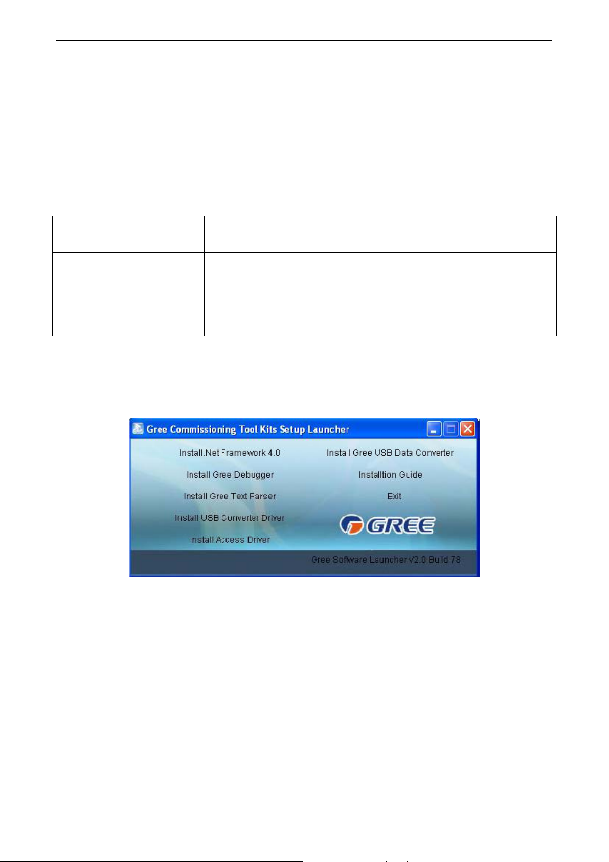
For the first time to use Gree Commissioning Tool Kits, install these programmes: .Net Framework
4.0, USB Data Converter, Access Driver (necessary for versions below OFFICE 2007), Gree Debugger.
25
Page 28
Duct type split Air conditioner Inverter Series
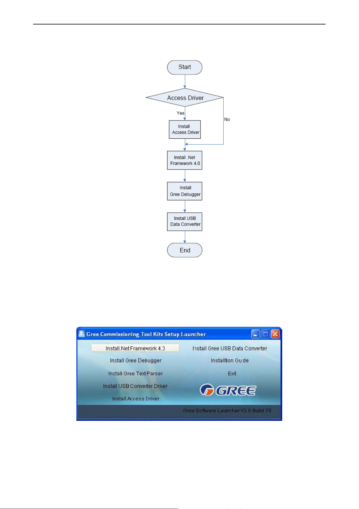
4.4.1.1 Installation flowchart
Button Graphics
This flowchart describes basically the software installation process. See below for details.
4.4.1.2 Installation process
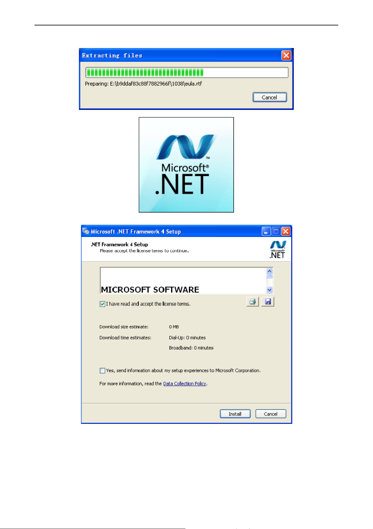
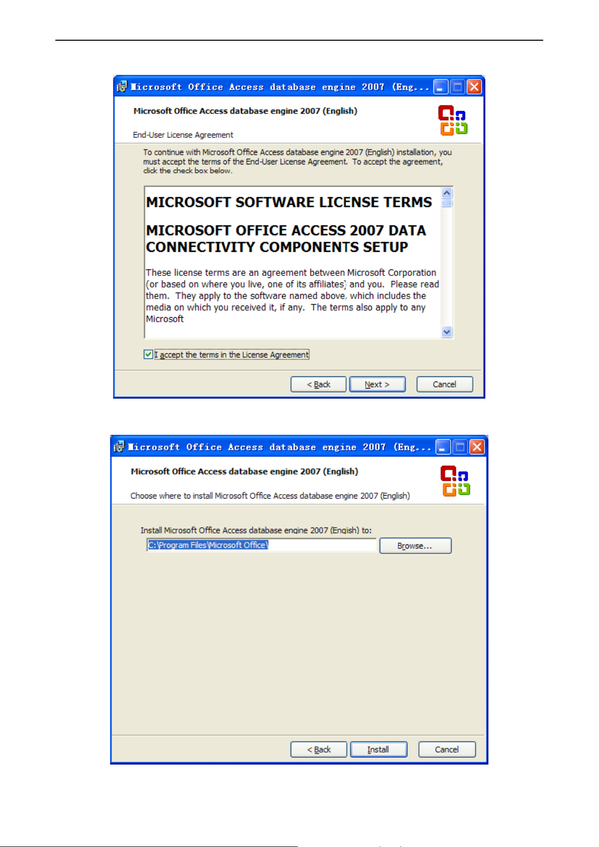
(1) Install .Net Framework 4.0
If your computer has installed .Net Framework 4.0 or versions above, there’s no need to install
again. Otherwise, click “Install .Net Framework 4.0”.
26
Page 29
Extracting files
Duct type split Air conditioner Inverter Series
Click and select “I have read and accept the license terms”. Then click “Install”.
27
Page 30
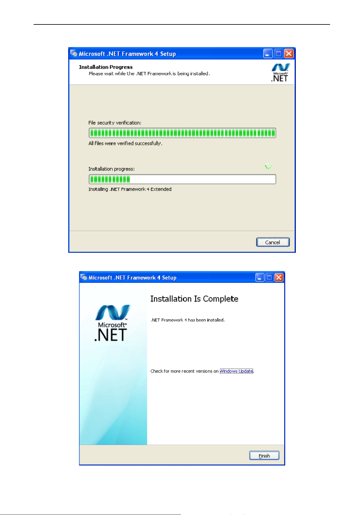
Installation is in progress.
Duct type split Air conditioner Inverter Series
Click “Finish” to complete the installation.
28
Page 31

Duct type split Air conditioner Inverter Series
(2) Install Access Driver
Before operating Gree commissioning software, please first install Access Driver (necessary for
versions below OFFICE 2007). Click “Install Access Driver”.
Click ”Next”.
29
Page 32
Duct type split Air conditioner Inverter Series
Tick “I accept the terms in the License Agreement” and then click “Next”
Click “Browse” to change the default folder to the expected one, or click “Install” to continue the
installation.
30
Page 33

Installation is in progress.
Duct type split Air conditioner Inverter Series
Click “Ok” to complete the installation.
(3) Install Gree Debugger
Before installing Gree debugger, make sure that your computer is installed with .Net Framework
4.0 or versions above. Then click “Install Gree Debugger”.
31
Page 34

Click “Next”.
Duct type split Air conditioner Inverter Series
Click “Browse” to select installation folder. If no change is needed for the folder, click “Next” to
continue the installation.
32
Page 35

Click “Next”.
Duct type split Air conditioner Inverter Series
Installation is in progress.
33
Page 36

Duct type split Air conditioner Inverter Series
Click “Close” to complete the installation.
(4) Install USB Converter Driver
If USB converter driver is already installed in your computer, this part can be skipped. Otherwise,
click “Install USB Converter Driver”.
34
Page 37

Duct type split Air conditioner Inverter Series
Then the following installation window will be shown.
This window will exit after installation is finished.
35
Page 38

Duct type split Air conditioner Inverter Series
(5) Install Gree USB Data Converter
If converter baud rate is needed to be set, then converter configuring software must be installed.
Click “Install Gree USB Data Converter”.
Then select the setup language. You can choose Chinese ”simplified”, Chinese “traditional” or
English. Then click “OK”.
Click “Next”.
36
Page 39

Duct type split Air conditioner Inverter Series
Tick “I accept the agreement”. Then click “Next” to continue installation.
Click “Browse” to select your expected installation folder. Click “Next” to continue.
37
Page 40

Duct type split Air conditioner Inverter Series
Click “Browse” to change folder. Click “Next” to continue.
If you want to create s desktop shortcut, tick “Creat a desktop icon”. Then click “Next” to continue.
38
Page 41
Duct type split Air conditioner Inverter Series
Destiniation location, folder and additional task will be shown in the next step. If you need to change
any of it, please click “Back”. If not, click “Install” to start installation.
Installaiton is in progress.
39
Page 42

Duct type split Air conditioner Inverter Series
Click “Finish” to complete the installation.
4.4.2 Data monitoring
Start up Gree Debugger.
On the original interface, user can select language and units system. Click “OK” to confirm the
defaulted language and units system and start up the software.
40
Page 43

Select language.
Select system of units.
Duct type split Air conditioner Inverter Series
41
Page 44

Duct type split Air conditioner Inverter Series
If units you want to monitor are already connected, and able to communicate normally, with correct
COM and protocal, then you may click “Connect” to enter the interface of numbers. Otherwise,
connect in accordance with the connection diagram shown below.
COM selection: the serial port in your computer can be detected automatically. You just need to
select your desired serial port.
42
Page 45

Duct type split Air conditioner Inverter Series
Protocal selection: This is to select the communication method of your units. Currently, CAN is
applicable to the units.
After the selection, click “Connnect”. If units can communicate normally with computer, then the
interface of numbers will be shown soon. Otherwise, “Connecting” will be shown.
43
Page 46

Duct type split Air conditioner Inverter Series
There are several display zones on this interface. You can hide devices information and system
information by clicking devices information icon and system icon . Display zones of indoor
unit information and errors can be dragged up and down at the dividing lines. As to the display zone
of outdoor modules information, it can show information of only one module and hide information of
others (two modules are defaulted to be shown). Menu bar can be hidden by clicking icon .
Status bar shows the current time and period for data collection.
Title bar
Error display
System info
Outdoor modules info
Devices info
Menu bar
44
IDU info
Status bar
Page 47

Duct type split Air conditioner Inverter Series
On the display zone of devices information, you may click to select and view units that need
monitoring.
4.4.3 Project debugging
Click icon of “Debug” on the menu bar and the interface will be switched to project debugging,
where auto debugging will be started from up to down and from left to right. Note: Debugging
function is only applicable to a single-system network.
45
Page 48

Duct type split Air conditioner Inverter Series
Click “Start” to enable the debugging function. Then debugging will be started up automatically.
indicates that debugging is in progress while indicates debugging is completed.
If “OK” button is displayed, it means user needs to judge whether to continue debugging or not.
Click icon and relevant information will be shown for your reference. Click “Close” to close the
pop-up (For No.3 Confirm ODU Basic Module NO. and No.4 Confirm IDU NO., the current number
of units under debugging will be displayed. See the following marked with circle. For No.8 Compr.
Preheat Confirmation, the preheat time will be displayed. See the following marked with circle).
46
Page 49

Duct type split Air conditioner Inverter Series
Icon indicates that there is problem found during debugging. Debugging will not be completed
unless problem is solved (after problem is solved, step without “OK” button will switch to the next
step automatically, otherwise user needs to click “OK” to continue). Click icon and relevant
information detected in this step will be displayed for your reference in order to solve problems.
Click “Close” to close the pop-up.
During debugging, a click on “Break” can stop debugging. Click “Start” to resume debugging and
then debugging will be finished step by step. For No.10 ODU Valves Check Before Startup, there
are “Back” and “Skip” buttons. If there is error in this step, you can back to step No.9 and click “OK”
to restart debugging on step No.10. If the error in step No.10 is U6 error (valve error alarm), you can
click “Skip”. In other cases, “Skip” button is null.
Step 11, 13 and 14 are reserved steps. And step 13, 14, 15 and 16 are steps in parallel (only one of
the four will be selected according to actual needs).
47
Page 50

Duct type split Air conditioner Inverter Series
4.4.4 Control units
Click icon of “Setting” on menu bar and select parameter settings, which include “Gateway Settings”,
“IDU Settings”, “System Settings”, “Project Number Conflict (In case there is project number conflict
in indoor units, other functions will be shielded. Then this parameter needs to be set in order to
eliminate the conflict)” and “System Historical Info”. Click the corresponding set and adjust the
parameters.
Take indoor unit as an example. Click “IDU Settings” and a dialog box will pop up.
48
Page 51

Duct type split Air conditioner Inverter Series
Tick the indoor units that need setting in the IDU selection zone or you may click “Select All” to
select all of them or “Select Inverted” to select none of them. After selection, the current values of
the corresponding parameters will be displayed in the zone of settings. Click “Set” and then click
in the pop-up dialog box to select values. Click “Set” and then the corresponding order will be
sent to units. If setting is successful, it will be displayed at the current values.
49
Page 52

Duct type split Air conditioner Inverter Series
4.4.5 Other functions
Capture screen
Click icon of “Capture Screen” to print the interface. If you want to open the interface, click “Open”.
50
Page 53

Duct type split Air conditioner Inverter Series
Search for database folder
Click icon of “Open Data Folder” on the menu bar to open database folder.
51
Page 54

Duct type split Air conditioner Inverter Series
Conversion of pressure value
Click icon of “Others” on the menu bar and then click “Display Settings” to select “High Low
Pressure Value” and “Refrigerant Type”. Select “Temperature” and the pressure parameter
displayed on the interface will be temperature. Select “Pressure” and the pressure parameter
displayed on the pressure interface will be pressure. Refrigerant type will affect the pressure
parameter displayed on the interface.
52
Page 55

Duct type split Air conditioner Inverter Series
Database saving of multiple systems
Click icon of “Others” on the menu bar and click “Database Save Settings” to select which system
that needs to save database. Because there is a large quantity of data in a network that contains
multiple systems, data of only one system can be saved.
53
Page 56

Duct type split Air conditioner Inverter Series
Change database saving path and rebuild database
Change of database saving path and rebuilding of database should be set before the software
starts monitoring (see below interface). Click “Change database saving path” and click “Browse” to
change the saving path. Click “Rebuild Database” to rebuild the database folder. You can also stop
monitoring and turn back to the connection interface to change saving path or rebuild database
during monitoring.
54
Page 57

Duct type split Air conditioner Inverter Series
4.4.6 Usage of USB Converter
Usage of converter
Gree commissioning software should be connected with CAN interface when converter is used. For
air conditioners with a single system, connect D1 and D2 interfaces of the wiring board. For air
conditioners with multiple systems, connect G1 and G2 interfaces of the wiring board.
Gree monitoring software should be connected with RS485 interface when converter is used.
Connect outdoor or indoor units or the mainboard of wired controller according to actual needs.
HBS, CAN and RS485 of the converter can be switched by buttons. Press the button “SET” on the
converter to realize the conversion among HBS, CAN and RS485 interfaces. You can check the
setting through the function LEDs.
Notice: If it’s the first time your PC uses Gree USB data converter, in order to prevent Gree USB
data converter from being mistaken by your computer as other devices and make sure your mouse
can work well, it is necessary to turn off the Serail Enumerator of computer after Gree USB data
converter is connected. Below are the steps:
Step 1: Right-click ”My Computer” on the desktop and click ”Manage”.
Step 2: In the pop-up window, select “Device Manager” in the left column and then find “Port
(COM and LPT)” in the right column. Click its .
55
Page 58

Duct type split Air conditioner Inverter Series
56
Page 59

Duct type split Air conditioner Inverter Series
Step 4:
Right-click ”USB Serial Port (COM6) and then click ”Properties”. The dialog box of properties will
then pop up.
Step 5: Then click ”Port Settings” in the dialog box.
57
Page 60

Duct type split Air conditioner Inverter Series
Step 6: Click ”Advanced” and then a new dialog
box will pop up. Find the ”Serial Enumerator” in
the miscellaneous options and cancel the tick. Click ”OK” to exit.
58
Page 61

Duct type split Air conditioner Inverter Series
Usage of converte
r configuring software:
When the converter is working, hold the button ”SET” for 5 sec. Function LED will be flickering,
indicating that the converter has enter the baud rate setting mode. Then you can use the converter
configuring software to set the baud rate of converter. Baud rate supported by the converter (baud
rate of air conditioner’s communication interface matches with the baud rate of USB interface
automatically):
Ex-factory defaulted baud rate: (unit: bps)
AC is connected with Baud rate of air conditioner interface Baud rate of USB interface
CAN 20000/50000 self-adaptive 115200
HBS 57600 38400
RS485 9600 9600
Baud rate look-up table for RS485 interface (unit: bps)
RS485 interface
USB interface
HBS interface
USB interface 4800
4800 9600 19200 38400 57600 115200
4800 9600 19200 38400 57600 115200
Baud rate l
9600 19200
Baud rate look-up table of CAN interface (unit: bps)
ook-up table for HBS interface (unit: bps)
38400
9600 19200
57600
38400
CAN interface
USB interface
20000 50000 100000 125000
115200 115200 256000 256000
Double-click the desktop shortcut.
59
Page 62

Duct type split Air conditioner Inverter Series
Select the needed communication serial port and language in the “System Settings”.
Select the function that is to be set and the corresponding baud rate (refer to the look-up table) in
the “Converter Setup”.Then click “Set”.
60
Page 63

Duct type split Air conditioner Inverter Series
If you want to restore ex-factory settings, click “Default” to restore the default settings.
Click “Get” to get the current setting details of converter.
61
Page 64

Duct type split Air conditioner Inverter Series
Switchover of Software Languages
62
Page 65

Duct type split Air conditioner Inverter Series
INSTALLATION
63
Page 66

Duct type split Air conditioner Inverter Series
1 Engineering Installation Preparation and
Notice
1.1 Installation notice
Personnel and property safety are highly concerned during the entire installation process.
Installation implementation must abide by relevant national safety regulations to ensure personnel and
property safety.
All personnel involved in the installation must attend safety education courses and pass
corresponding safety examinations before installation. Only qualified personnel can attend the
installation. Relevant personnel must be held responsible for any violation of the regulation.
1.2 Installation key points and importance
The system use refrigerant, instead of other agent, to directly evaporate to carry out the system heat.
High level of pipe cleanness and dryness is required in the system. Since various pipes need to be
prepared and laid out onsite, carelessness or maloperation during installation may leave impurities,
water, or dust inside refrigerant pipes. If the design fails to meet the requirement, various problems may
occur in the system or even lead to system breakdown.
Problems that usually occur during installation are as follows:
No. Installation Problem Possible Consequence
are more likely to be blocked; air conditioning performance is reduced;
Dust or impurities enter into the
1
2
3
4
5
6
7
8
9
10
11
12
13
refrigeration system.
Nitrogen is not filled into the
efrigerant pipe or insufficient
r
Nitrogen is filled before welding.
The vacuum degree in the
r
efrigerant pipe is insufficient.
Water enters into
the refrigeration
system.
The refrigerant pipe
pecifications do not meet the
s
configuration requirements.
Refrigerant pipe is
Refr
igerant pipe exceeds the
Incorrect amount of refrigerant is
The refrigerant pipe leaks.
Water drainage from
condensate water pipe is not
smooth.
The ratio of slop for condensate
water pipe is insufficient or the
ondensate water pipe is
c
incorrectly connected.
channel is improperly
The air
The guide vane of air channel is
not reasonably manufac
blocked.
limit.
filled.
fixed.
the
tured.
Pipes
compressor wear is increased or even hinder the normal operation of the system
are more likely to be blocked; air conditioning performance is reduced;
Pipes
compressor wear is increased or even hinder the normal operation of the system
The refrigeration performance is reduced. The system fails to keep normal
ation due to frequent protection measures. When the problem getting serious,
oper
Copper
efficiency with abnormal noise generated; failures may occur in the system due to
maller configuration specifications can increase the system pipe resistance and
S
affect the cooling performance; larger configuration specifications are waste of
The c
compressor operating under overheat conditions; the lubricating effect can be
affected and the compressor may be burnt if impurities were mixed with the
The loss in pipe is c
The system cannot correc
operating under over-heating environment or running when the refrigerant flows
Insufficient refrigerant circulating in the s
of the air conditioner. Long-term operation under such circumstance may cause an
Res
Rev
The air
compressor and other major components can be damaged.
plating may appear on the compressor and reduce the compressor
materials and can also reduce the cooling performance.
ooling performance is reduced; in certain cases, it may cause long-term
are harmful for long-term running of the system.
overheating compressor or even damage the compressor.
idual water in IDUs can affect the normal operation of the system. The
possible water leakage can damage the IDU's decoration.
erse slop or inconsistent connection of condensate water pipe can hinder the
smooth drainage and cause leakage of the IDU.
channel will deform; vibration and noise occur during unit operating.
Unev
en air quantity allocation reduces the overall performance of the air
and burn the compressor.
and burn the compressor.
ice plug.
lubricating oil.
onsiderable and the unit energy efficiency decreases, which
tly control the flow allocation; the compressor may be
back to the compressor.
ystem decreases the cooling performance
conditioner.
64
Page 67

Duct type split Air conditioner Inverter Series
No. Installation Problem Possible Consequence
The refr
condensate water pipe does not
14
meet the insulation requirement.
igerant pipe or
can easily condensate and drip to damage the indoor decoration, or even
Water
trigger the protection mode of system due to overheating operation.
The installation space for IDU is
15
The IDU or the location of the air
outlet or return air inlet is not
16
The ODU is improperly ins
17
Power c
18
Control communication cables
19
20
ar
Control communication cables
are not pr
insufficient.
designed r
e incorrectly provided or
improperly connected.
easonably.
ables are incorrectly
provided.
operly protected.
talled.
Since there is a lack of s
might need to be damaged during such operation.
The air outlet or r
The ODU is difficult to be maintained; unit exhaust is not smooth, which reduces
the heat exchanging performance or even prevent the system from norm
operation; in addition, the cold and hot air for heat exchange and the noise may
Unit components may be damaged and potential safety haz
The normal communication in the system fails or the contr
The communication cables are short-circ
cannot be started up due to communication failure.
pace for maintenance and checking, indoor decoration
eturn air inlet may be short-circuited, thus affecting the air
conditioning performance.
al
annoy people in surrounding areas.
ard may occur.
ol over IDUs and ODUs
turn in a mess.
uited or disconnected, and the unit
Understand the special requirement (if any) for unit installation before implementation to ensure
installation quality. Relevant installers must have corresponding engineering construction qualifications.
Special type operators involved in the engineering implementation, such as welders, electricians,
and refrigeration mechanics must have relevant operating licenses and are accredited with vocational
qualification certification.
2 Installation Materials Selection
The materials, equipment and instruments used during air conditioning engineering construction
must have certifications and test reports. Products with fireproof requirements must be provided with
fireproof inspection certificates and must meet national and relevant compulsory standards. If
environmentally-friendly materials are to be used as required by customers, all such materials must
meet national environmental protection requirement and be provided with relevant certificates.
2.1 Refrigerant piping
a. Material requirement: Dephosphorization drawing copper pipe for air conditioners;
b. Appearance requirement: The inner and outer surface of pipe should be smooth without pinhole,
crack, peeling, blister, inclusion, copper powder, carbon deposition, rust, dirt or severe oxide film, and
without obvious scratch, pit, spot and other defects.
c. Test report: Certifications and quality test reports must be provided.
d. The tensile strength must be at least 240 kgf/mm².
e. Specifications requirement
R410A Refrigerant System
OD (mm/inch) Wall Thickness (mm) Model
0.8
Ф6.35(1/4)
Ф9.52(3/8)
65
≥
≥
0.8
0
0
Page 68

Duct type split Air conditioner Inverter Series
0.8
Ф12.70(1/2)
Ф15.9(5/8)
Ф19.05(3/4)
Ф22.20(7/8)
Ф25.40(8/8)
≥
≥
≥
≥
≥
1.0
1.0
1.2
1.2
f. After the inner part of the copper pipe is cleaned and dried, the inlet and outlet must be sealed
tightly by using pipe caps, plugs or adhesive tapes.
2.2 Condensate water pipe
a. Pipes that can be used for air conditioner drainage include: water supplying UPVC pipe, PP-R
pipe, PP-C pipe, and HDG steel pipe;
b. All relevant certificates and quality test reports are provided.
c. Requirements for specifications and wall thickness
Water supplying UPVC pipe: Φ32mm×2mm,Φ40mm×2mm,Φ50mm×2.5mm;
0
0
0
0
0
HDG steel pipe: Φ25mm×3.25mm,Φ32mm×3.25mm,Φ40mm×3.5mm,Φ50mm×3.5mm.
2.3 Insulation material
a. Rubber foam insulation material;
b. Flame retardancy level: B1 or higher;
c. Refractoriness: at least 120℃;
d. The insulation thickness of condensate water pipe: at least 10 mm;
e. When the diameter of copper pipe is equal to or greater than Φ15.9 mm, the thickness of
insulation material should be at least 20 mm; when the diameter of copper pipe is less than 15.9 mm, the
thickness of insulation material should be at least 15 mm.
2.4 Communication cable and control cable
Note: For air conditioning units installed in places with strong electromagnetic interference, shielded
wire must be used as the communication cables of the IDU and wired controller, and shielded twisted
pairs must be used as the communication cables between the IDU and ODU.
Communication cable selection for ODU and IDUs
Total Length L
(m/feet) of
Material Type
Light/Ordinary
polyvinyl
chloride
sheathed cord.
(60227 IEC 52
/60227 IEC 53)
Communication
Cable between
Indoor Unit and
Indoor (Outdoor)
Unit
L≤1000m
(L≤3280-5/6feet)
Wire size
2
/AWG)
(mm
2×0.75
≥
(≥2×AWG18)
:
Material
Standard
IEC
60227-5:2007
Remarks
1. If the wire diameter is enl arged to 2×1
2
mm
(2×AWG16), the total
communication line length can reach
1500 m (4921-1/4feet).
2. The cord shall be Cir cular co rd (the
cores shall be twisted together).
3. If unit is installed in places with intense
magnetic field or strong interference, it
is necessary to use shielded wire.
Communication cable selection for IDU and wired controller:
66
Page 69
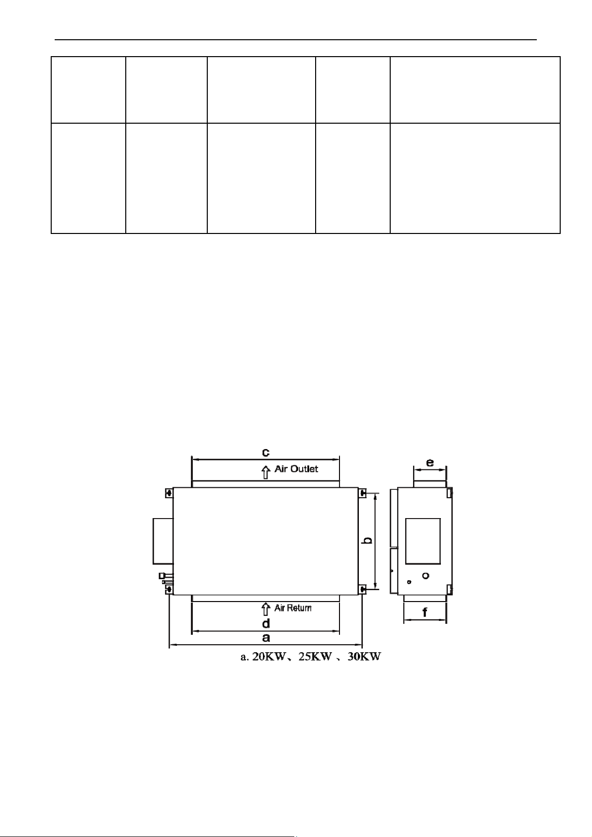
Duct type split Air conditioner Inverter Series
Total length of
communication
Material type
Light/Ordinary
polyvinyl
chloride
sheathed
cord.(60227
IEC 52
/60227 IEC 53)
line between
indoor unit and
wired controller
L (m/feet)
L≤250m
(L≤820-1/5feet)
2
Wire size (mm
2×0.75~2×1.25
(2×AWG18~2×AWG16)
/AWG)
Material
Standard
IEC
60227-5:2007
Remarks
1.Total length of communica
e can't exceed 250m
lin
(820-1/5fee
.The cord shall be Circ ular cord
2
(the cores shall be twisted
together
3.If unit is
in
tense magnetic field or st
in
terference, it is necessary
u
se shielded wi
t).
).
installed in places wi
re.
2.5 Power cable
Only copper conductors can be used as power cables. The copper conductors must meet relevant
national standard and satisfy the carrying capacity of unit.
2.6 Hanger rod and support
a. Hanger rod: M8 or M10;
tion
th
rong
to
b. U-steel: 14# or above;
c.
Angle steel: 30mm×30mm×3mm or above;
d. Round steel: Φ10mm o
r above
3 Installation of Indoor Unit
3.1 Outline and installation dimension
67
Page 70

Duct type split Air conditioner Inverter Series
b. 40kW
Below are dimensions of A, B, C, etc. for different models:
Unit: mm
Model
FGR20Pd/DNa-X(I)
FGR25Pd/DNa-X(I)
FGR30Pd/DNa-X(I)
FGR40Pd/D(2)Na-X(I)
a
1334 632 990 1150 192 363
1541 705 980 1350 270 420
1541
1730 760
3.2 Installation space
b
705
c
980 1350
1054 1450 360 560
d
e
270
f
420
3.3 External static pressure setting and reading
3.3.1 External static pressure setting
You can enter P67 select the way of adjusting static pressure for the blast pipe m
automatically.The default value is 00,which means adjusting manually.
(1) If you choose 00,you can select the suitable level for any blast pipes. It can reach to 250Pa
68
anually or
Page 71

Duct type split Air conditioner Inverter Series
.You can enter P30 to set the value.
① Long press FUNCTION button for 5s and the temperature zone displays “C00”; long press
FUNCTION button for another 5s to enter the interface of s
etting wired controller parameters. “P00” is
displayed in temperature zone.
② Press “▲” or “▼” button to select parameter code. Press MODE button to enter parameter setting.
At that time, parameter value is blinking. Press “▲” or “▼” button to adjust the parameter value and
press ENTER/CANCEL button to finish setting.
③ Press ENTER/CANCEL button to return to last step until exists setting parameters.
The parameter setting list is as following
Parameter
code
30
P
Param
eter name
Set static pressure of indoor
fan motor
Parameter range
01-09: static pressure level of
indoor fan motor
Default
alue
v
05
Note
Ther
e are 9 static
pressure level:
01, 02, 03, 04, 05, 06,
07, 08, 09
Note:
① Under parameter setting status, FAN, TIMER, SLEEP and SWING button are invalid. Press
ON/OFF button to go back to home page, but not turning on/off the unit.
② If the power cord is more than 15 m (49-1/4 ft.) long, please increase properly the sectional area of
power cord to avoid overload, which may cause accident.
External Static Pressure s
0 inWG(0 Pa) 01
0.12 inWG(30 Pa) 02
0.24 inWG(60 Pa) 03
0.36 inWG(90 Pa) 04
0.48 inWG(120 Pa) 05
0.60 inWG(150 Pa) 06
0.72 inWG(180 Pa) 07
0.84 inWG(210 Pa) 08
1.00 inWG(250 Pa) 09
tatic pressure level of indoor fan motor
Note:
Keep in mind that a shortage of airflow quantity or water leakage will result because the air conditioner
will be operated outside the rated range of airflow quantity if the external static pressure is wrongly set.
(2) If you choose 01,the indoor motor will adjust static pressure of the blast pipe automatically
when start-up every time.So how to enter P67?
Long press FUNCTION button for 5s and the temperature zone displays “C00”; press MODE button
①
for three times in 3s;long press FUNCTION button for another 5s to enter the interface of setting wired
controller parameters. “P00” is displayed in temperature zone.
② Press “▲” or “▼” button to select parameter code. Press MODE button to enter parameter setting. At
69
Page 72

Duct type split Air conditioner Inverter Series
that time, parameter value is blinking. Press “▲” or “▼” button to adjus
t the parameter value and press
ENTER/CANCEL button to finish setting.
(3) Press ENTER/CANCEL button to return to last step until exists setting parameters.
The parameter setting list is as following
Parameter code P
P67 Select the way of adjusting static pr
arameter name
essure
Parameter range Default value
00: manually
01:automatically
3.3.3 External static pressure reading
If you want to know the exact external static pressure,you can set P67 to 01,restart the
machine,after about 2 minutes,enter C24 to read the exact ESP.
00
① Long press FUNCTION button for 5s and the temperature zone displays “C00”; press MODE button
for three times in 3s.
② Press “▲” or “▼
” button to C24,there you can read the exact ESP.
3.4 Installation notice
◆The unit shall be installed by the professional personnel according to this installation instruction
ensure proper use.
malfunctioncaused by the unit that is not installed by the Gree appointed service center would probably
not be dealt with on time because of the inconvenience of the busines
other plac
c
to
◆ Pleas
e contact the local Gree appointed service center before installation. Any
s contact.
◆
It should be guided under the professional personnel when the air conditioner unit is moved to
e.
◆Installation of the unit must be in accordance with National Electric Codes and local regulations.
◆Improper installation will affect unit’s performance, so do not install the unit by yourself. Please
ontact local dealer to arrange professional technicians for the installation.
◆
Do not connect power until all installation work is finished.
◆If the supply cord is damaged, it must be replaced by the manufacturer or its service agent or a
imilarly qualified person in order to avoid a hazard.
s
3.5 Selection of air switch and power cord
Model Power supply
FGR20Pd/DNa-X(I)
220V~50/60HZ
Circuit
breaker
capacity
(A)
10 1×1.5 2×1.5
70
2
)Number of
(mm
ground wire * Min
sectional area
(mm
2
)
2
(mm
power cord * Min
sectional area
(mm
)Number of
2
)
Page 73

Duct type split Air conditioner Inverter Series
FGR25Pd/DNa-X(I)
FGR30Pd/DNa-X(I)
FGR40Pd/D(2)Na-X(I)
220V~50/60HZ
220V~50/60HZ
3N~ 380V 50/60HZ
10 1×1.5 2×1.5
10 1×1.5 2×1.5
10 1×1.5 4×1.5
4 Installation of outdoor unit
4.1 Check before installation
a. Before installation, please check the power cord if it complies with the power supply requirement
on the nameplate. Make sure the power supply is safe.
b. This air conditioner must be properly grounded through the receptacle to avoid electric shock.
The ground wire shouldn’t be connected with gas pipe, water pipe, lightning arrester or telephone line.
c. Maintain good air circulation to avoid lacking oxygen.
d. Read this manual carefully before installation.
4.2 Selection of installation site
a. Select a location which is strong enough to hold unit’s weight so that unit can stand still and erect.
b. Make sure the unit is not exposed to sun and rain. And the location can resist dust, typhoon and
earthquake.
c. Please keep the unit away from inflammable, explosive and corrosive gas or waste gas.
d. Make sure the location has space for heat exchange and maintenance so that unit can operate
reliably with good ventilation.
e. ODU and IDU should stay as close as possible to shorten the length of refrigerant pipe and
reduce bend angles.
f. Select a location which is out of children’s reach. Keep the unit away from children.
4.3 Carrying and installing outdoor unit
When carrying the outdoor unit, hang the unit in four directions with two sufficient ropes. In order to
avoid excursion from the center, the angel of ropes must be smaller than 40º during hanging and
moving.
4.4 Installation notices
In order to ensure proper operation, the selection of installation site must conform to the following
principle:
●The discharged air of outdoor unit will not flow back and there is sufficient space around the unit
for maintenance;
●The installation site must be well ventilated to ensure sufficient air intake and discharge. Make
sure there is no obstacle at the air inlet and air outlet. If there is any obstacle, please remove it;
●The installation site shall be able to withstand the weight of outdoor unit and capable for
soundproof and vibration. The air outlet and noise of unit will not affect neighbors;
●The hanging of outdoor unit must use appointed hanging hole. Pay attention to protect the unit
during hanging and installation. Prohibit hitting the sheet metal to avoid rust in the future.
●Avoid direct sunlight;
71
Page 74

Duct type split Air conditioner Inverter Series
●The rain and condensation water can be drained out smoothly;
●The outdoor unit will not
be embedded by the snow and not affe
●The installation of outdoor unit shall
adopt rubber damping pad or spring damper to reduce noise
cted by garbage and oil smog;
and vibration;
●The installation dimension shall accord with the installation requirement of this manual and the
outdoor unit must be fixed at the installation site;
●The installation shall be done by professional tech
nicians.
4.5 Fixing and damping of unit
The outdoor unit shall be fixed with 4 M12 bolts and closely contacted with the foundation.
Otherwise, big vibration and noise will be caused.
The outdoor unit shall be fixed firmly. The rubber board with thickness over 20mm or corrugated
rubber damping pad shall be applied between the unit and foundation.
4.6 Outline dimension and position of installation hole
When carrying the outdoor unit, hang the unit in four directions with two sufficient ropes. In order to
avoid excursion from the center, the angel of ropes must be smaller than 40º during hanging and
moving.
Model
FGR20Pd/DNa-X(O)
FGR25Pd/DNa-X(O)
A B C D E
940 320
940 460
72
143
161
0
5
632
610
Unit: mm
350
486
Page 75

Duct type split Air conditioner Inverter Series
FGR30Pd/DNa-X(O)
940 460
161
5
610
4.7 Installation space requirement
If all sides of the ODU (including the top) are surrounded by walls, process according to the
following requirements for installation space:
5 Installation of drain pipe
5.1 Precautions When Doing the Piping Work
Keep piping as short as possible and slope it downwards at a gradient
◆
of at least 1/100 so that
486
air may not remain trappe
For example:
Keep pipe
◆
Install the
◆
piping could l
When directly connecting a hard vinyl chloride pipe joint to the drain hose connected to the indoor
◆
size equal to or greater th
drain piping as shown and take measures against condensat
ead to leaks and eventually wet furniture and belongings.
d inside the pipe.
an that of the connecting pipe.
ion. Improperly rigged
unit, use a commercially available hard vinyl chloride pipe joint (nominal diameter 13mm).
73
Page 76

Duct type split Air conditioner Inverter Series
Drain hose connectedto the indoor unitCommercially availablehard vinyl chloride pipejoint
◆
(nominal diameter 13mm)Commercially availablehard vinyl chloride pipe(nominal diameter 13mm)
Do not connect the drain piping directly to sewage pipes that smell of ammonia. The ammonia in
◆
the sewage might enter the indoor unit through the drain pipes and corrode the heat exchanger.
5.2 Installing the Drain Pipes
Insert the drain hose into the drain outle
◆
t, and tighten the clamp securely with tape.
Tighten the clamp until the screw head is less th
◆
Insulate the pipe clamp and the drain hose using heat insulation sponge.
◆
If the air flow of indo
◆
of outdoor air. Therefore, U-type water trap shall be designed on the drainage side of each indoor unit.
or unit is high, this might cause negative pressure and result in return suction
en 4 mm from the hose.
Install water trap as shown below
◆
Install one water trap for each unit
◆
Installation of water trap shall consid
◆
Connection of drainage branch pipe to the standpipe or horizontal pipe of drainage main
◆
The ho
◆
connected in a manner as shown belo
N01:3-way connection of drainage pipe joint
rizontal pipe cannot be connected to the vertical pipe at a same height.
w:
er easy cleaning in the future.
pipe
It can be
74
Page 77

Duct type split Air conditioner Inverter Series
NO2: Connection of drain elbow
NO3: Connection of horizontal pipe
When unifying multiple drain pipes, install the pipes as shown below. Select converging drain
◆
pipes whose gauge is suitable for the operating capacity of the unit.(take the cassette type unit for
example)
5.3 Precautions when doing riser piping work
Make sure that heat insulation work is executed on the following 2 spots to prevent an
◆
75
y possible
Page 78

Duct type split Air conditioner Inverter Series
water leakage due to dew condensation.
a) Con
b) Con
◆
the drain outl
◆
supporting br
nect the drain hose to the drain
nect the drain hose to the drain outlet on the indoor unit, and tighten it with the clam
Stand the raiser piping horizontally, and make sure it is not further than 300 mm from the base
Secure a downward gradient of 1/100 or more for the drain pipe. To accomplish th
raiser pipe, and insulate them.
p.
of
et.
is, mount
ackets at an interval of 1 - 1.5 m.(take the cassette type unit for example)
The incline of attached drain hose should be 75 mm or less so that the drain outlet does not have
◆
to withstand additional force.(take the cassette type unit for example)
5.4 Testing of Drain Piping
After piping work is finished, check if drainage flow
◆
n in the figure, Add approximately 1liter of water slowly into the drain pan and check
Show
◆
drainage flow during COOL running.
s smoothly.
6 Electrical Installation
76
Page 79

Duct type split Air conditioner Inverter Series
The wiring must be in accordance with the local rules.
◆
Rated supply voltage and special circuit for air conditioner must be used.
◆
Do not pull the power cord forcefully.
◆
All the electric installations must be carried out by specialist technicians in accordance with the
◆
local laws, rules and these instructions.
The diameter of flexible wire should be wide enough. Replace the damaged power cord and
◆
connecting wire with special flexible wire.
The earthing shall be reliable and connected to the special earthing device on the construction.
◆
The installation must be done by specialist technicians. The leak protection switch and air switch with
enough capacity must be installed. The air switch shall have both the magnetic tripping and thermal
tripping functions to ensure protection against the short circuit and overload.
● Earthed Requirements
The air conditioner belongs to I type electric appliances. The reliable earthed action is a must.
◆
The yellow and green wire inside the air conditioner is the earthed wire. Do not use it for other
◆
purpose or even cut off it. Do not fix it with tapping screw,. Otherwise, it may cause electric shock.
The earthed resistance must meet the requirements of national standard GB17790.
◆
There should be reliable earthed terminal for the power supply. Never connect the earth lead to
◆
the following articles:
water pipe; ②gas pipe; ③drain pipe; ④unreliable place considered by professionals.
①
77
Page 80

Duct type split Air conditioner Inverter Series
DEBUGGING & MAINTENANCE
78
Page 81

Duct type split Air conditioner Inverter Series
1 Debugging of Unit
Caution:
1.
After the initial installation is finished and the main board of outdoor unit is replaced, it must perform
debugging. Otherwise, the unit can’t operate.
2. The debugging must be performed by professional person or under the the guide of professional
person.
1.1 Preparation for debugging
(1) Do not disconnect the power before the installation is finished,
(2) All wires for controller and electric wires must be connected correctly and reliably.
(3) Check the the fixing ring of the foot of compressor for transportaion is removed.
(4) Remove all sundries from the unit, such as metal chips, joint, forceps holder, and so on.
(5) Check whether the appearance and pipeline system are damaged during carry or transportation
process.
(6) Calculate the required added refrigerant-charging volume according to the length of pipe of system
and pre-charge the refrigerant. If refrigerant can’t be added any more when the required
refrigerant-charging volume hasn’t been reached, record to refrigerant volume which still needs to
be added and continue to add refrigerant during run test operation process. Please refer to below
run test for the refrigerant-adding stage during run test process.
(7) After adding refrigerant, please make sure the valve for outdoor is opened completely.
(8) For the convenient of troubleshooting, the unit can’t be connected to the PC which installed with
related debugging software and make sure that the the datas in real time of this unit can be
inspected by this computer. Please refer to Service Manual for the installation and connection of the
bebugging software.
(9) Before turn test, please do make sure that the preheat time for compressor is 8h above and touch
the compressor to see whether preheat is normal. You can perform run test only after normal
preheat. Otherwise, it may damage the compressor.
1.2 Debugging of unit
1.2.1 flow-process diagram of debugging
79
Page 82

Duct type split Air conditioner Inverter Series
1.2.2 Test Operation and Debugging
Once the unit is energized and turned on for the first time, the display tube of outdoor unit displays
“A0”, which indicates debugging standby status. At this time, hold SW3 button successively for 5s on the
main module to enter into the automatic debugging, and then the engineering debugging will perform
according to the set procedures. Step 4(conformation of outdoor unit’ quantity) and step 4(conformation
of indoor unit’ quantity) should be confirmed manually by pressing “SW3”, while other procedures will be
performed automatically. Once the debugging for each step is finished, “oC” will be displayed; once all
engineering debugging are finished, “oF” will be displayed, which indicates the unit is under standby
80
Page 83

Duct type split Air conditioner Inverter Series
status.
Functions of debugging buttons:
Key No. SW1 SW2 SW3 SW4
Function Up Down OK Back
Buttons and digital display tube on the motherboard location:
Debugging procedure for test run, display instruction for indicator on main board of outdoor unit and
operation method are as below:
Description of each stage of debugging progress
—— Debugging Code
Progress
01_ Set master
unit
02_ Allocate
addresses
03_ Confirm the
quantity of ODU
LED
Display Code
01/CC
01/CF
01/OF
02 Flicker
02/L7
02/OC
03/QTY of module
03/OC
Display
Code
Display
repeatedly
Display
repeatedly
Display
repeatedly
Display
repeatedly
Display
repeatedly
Display
repeatedly
Display
repeatedly
There is no master unit in the system. The system cannot
continue to conduct debugging, and all the buttons are invalid
that must be reset by cutting the power.
There are two or more master units in the system. The system
cannot continue to conduct debugging, and all the buttons are
invalid that must be reset by cutting the power.
There is only one master unit in the system. The unit will
automatically enter into the next step after display for once.
The system is allocating addresses. It will display asbelow after
10 seconds:
There is no master unit. The display will last for 1 minute, within
this 1 minute, the master IDU can be set by debugging software.
If the master IDU has not been set within this 1 minute, the
system will automatically set the IDU with the minimum IP
address as the master IDU.
The system has finished allocating the addresses, there is
master IDU.It will automatically enter into the next step’s
operation after displaying for once.
Confirmation of quantity of modules in the system. If the actual
quantity of ODU is inconformity with the displayed quantity,
please check the dial code and wire connection and then
conduct debugging for confirmation.
If the actual quantity of ODU is in conformity with the displayed
quantity, press SW3 button to confirm. After confirmation, all the
module nixie tubes will repeatedly display “03” and “0C”, after
displaying for once, the system will automatically enter into the
next operation.
Instruction for Code and Operating Method
81
Page 84

—— Debugging Code
Progress
04_ Confirm the
quantity of IDU
05_ Detect ODU’s
internal
communication
06_ Detect
outdoor
components
07_ Detect indoor
components
08_ Confirm
preheated
compressor
09_Confirm status
of valve of ODU
10_Debugging
completed status
Display Code
04/Cb
04/oC
05/C2
05/oC
06/corresponding
error code
06/oC
07/ corresponding
error code
07/oC
08/U0
08/oC
09/U4
OFF On
Duct type split Air conditioner Inverter Series
Description of each stage of debugging progress
LED
Display
Code
Display
repeatedly
Display
repeatedly
Display
repeatedly
Display
repeatedly
Display
repeatedly
Display
repeatedly
Display
repeatedly
Display
repeatedly
Display
repeatedly
Display
repeatedly
Display
repeatedly
It is not allowed to connect more than one indoor unit in the
system. Please check and debug again to confirm.
The quantity of IDU in the system has been confirmed.It will
enter into the next step.
Communication between master control and driving of ODU.
Please check if the communication wire between
mainboard and driving board of ODU is correctly
connected, if it is, enter into the next step. If the ODU should be
powered off for the debugging, after re-energizing the unit,
please conduct debugging from the above 01 step.
The communication between master control and driving of ODU
are normal. After displaying for once, it will automatically enter
into the next step.
Error of components of ODU. Except “06”, others will flickeringly
display corresponding error code. After eliminating all the
errors, it will automatically enter into the next step. If the ODU
should be powered off for the debugging, after re-energizing the
unit, please conduct debugging from the above 01 step.
No component of ODU is found in the system, it will enter into
the next step 10 seconds later.
Error of components of IDU are detected. For example, the IDU
displays d5 and d6 simultaneously, the nixie tube will repeatedly
display “07”, “d5”, “d6”. After eliminating all the errors, it will
automatically enter into the next step. If the ODU should be
powered off for the debugging, after re-energizing the unit,
please conduct debugging from the above 01 step.
No component of IDU is found in the system, it will automatically
enter into the next step 5 seconds later.
Insufficiency preheating of compressor. The nixie tube will
display as the left until the preheating time for compressor has
reached 8 hours, then press SW3 can skip over the waiting
time, and automatically enter into the next step 2 seconds later.
(Note: if the preheating time for the compressor is less than 8
hours, there may be a risk for damage of compressor, please
conduct with care)
If the ODU is continuously energized for ≥8h, or the continous
8-hour energizing time in the last time till now is less than 2
hours (it requires clock chip), it means the preheating is
completed, the system will automatically enter into the next step
2 seconds later.
The system shuts down due to malfunction. The error module
nixie tube repeatedly display “09” and “U6”, other module nixie
tubes repeatedly display “09” and “J0”. If erroe occurs, please
check if the valve is opened, and at the same time check if the
connecting pipes between different modules are correctly
connected.
If all the modules shut down, then all the module nixie tube will
display “09” and “oC” for once.
The whole unit has gone through the debugging, the system is in
stand-by status.
Instruction for Code and Operating Method
1.3 Parameters reference value for the normal operation of unit
No. Debug item Parameter name Unit Reference
1
2
System
parameters
ODU
parameters
Outdoor temperature ℃ ——
●When compressor starts, discharge temp in
cooling mode is within 70~105 ℃ and at least
Compressor
discharge
temperature
82
10℃ higher than the high pressure saturation
℃
temp;
●As for temp in heating mode, it is within 65~90℃
and at least 10℃ higher than the high pressure
saturation temp.
Page 85

Duct type split Air conditioner Inverter Series
●In cooling mode, defrosting temp is 4~10 ℃
3
4
5 System low pressure ℃
6
7
8
9
10
11
12
13
14 Drainage system —— —
15 Others —— —
Communication
parameters
IDU
parameters
Defrosting
temperature
System high
pressure
Opening angle of
thermal EXV
Compressor working
current
Compressor’s IPM
temp
IDU ambient temp ℃ ——
Indoor heat
exchanger’s inlet
temp
Indoor heat
exchanger’s inlet
temp
Opening angle of
indoor EXV
Communication data —
lower than system’s high pressure value;
℃
●In heating mode, defrosting temp is about 2℃
different from system’s low pressure value.
●In cooling mode, the normal high pressure value
is within 20℃~55℃. According to the change of
ambient temp and system’s operating capacity,
the high pressure value will be 10℃~30℃ higher
than ambient temp. The higher ambient temp is,
the smaller temp difference is. If ambient temp is
℃
25~35℃ in cooling mode, system’s high pressure
value will be within 44~53℃.
●In heating mode, if ambient temp is above -5℃,
system’s high pressure value is within 40~52℃. If
ambient temp is low and many IDUs are turned
on, the high pressure will be lower.
●When ambient temp in cooling mode is 25~35℃,
the low pressure value is 0~8℃.
●When ambient temp in heating mode is above
-5℃, the low pressure value is -15~8℃.
●In cooling mode, the thermal electronic
expansion valve remains 480PLS.
PLS
●In heating mode, the adjustable opening angle of
EXV is 60~480PLS.
When compressor works normally, the current is
A
no more than 23.0A.
When ambient temperature is below 35℃, IPM
℃
temperature is lower than 70℃. Maximum
temperature is 80℃.
●According to ambient temp, for a same IDU in
℃
cooling mode, the inlet temp will be 1 ℃ ~7 ℃
lower than the outlet temp, and 4~9℃ higher than
the low pressure value.
℃
●For a same IDU in heating mode, the inlet temp
will be 10℃~20℃ lower than the outlet temp.
●In cooling mode, the opening angle of indoor
EXV varies within 40~480PLS.
PLS
●In heating mode, the opening angle of indoor
EXV varies within 70~480PLS.
Number of IDUs detected by software is the same
with the actual number. No communication error.
Indoor unit can drain water out completely and
smoothly. Condensate pipe has no backward
slope of water; Water of outdoor unit can be
drained completely through drain pipe. No water
drop from unit base.
Compressor and indoor/outdoor fan motor do not
have strange noise. Unit can operate normally.
2 Malfunction List
2.1 Malfunction list for the IDU
Display
code
L0
L1
L2
L3
Content
Malfunction of
indoor unit
Indoor fan
protection
E-heater protection
Water overflow
protection
Display
code
L9
LA
LH
LC
Wrong number of indoor
unit for one-to-more indoor
one-to-more indoor unit
Alarming due to bad air
The indoor unit model can’t
match with outdoor unit
Content
unit
Wrong series for
quality
model
83
Display
code
d8
d9 Malfunction of jumper cap
dA
dH
Abnormal PCB for wired
Content
Malfunction of water
temperature sensor
Abnormal address for
indoor unit
controller
Page 86

Duct type split Air conditioner Inverter Series
Power supply
L4
L5
L6
L7
L8
db Special code: engineering debugging code
of wired controller
is faulted
Freeze prevention
protection
Mode shock
No main indoor unit
Insufficient power
supply
d1 Poor indoor PCB dC
d3
d4
d6
d7
Malfunction of ambient
temperature sensor
Malfunction of entry tube
temperature sensor
Malfunction of exit tube
temperature sensor
Malfunction of humidity
sensor
dL
dE
C0
AJ Clean alarming for filter
Abnormal code-dialing
setting of capacity
Malfunction of air exhause
temperature sensor
Malfunction of indoor C0
sensor
Communication
malfunction
2.2 Status display table for indicators on main board of ODU
Display
code
E0
E3
F0
F5
J7
JL
b3
b6
bH
P2
Content
Malfunction of
outdoor unit
Low pressure
protection
Poor main board of
outdoor unit
Malfunction of
discharge
temperature sensor
for compressor 1
Air-mixing protection
for 4-way valve
High pressure is too
low
Maflunction of
defrosting
temperature sensor 2
Malfunction for
temperature sensor of
inlet tube of gas and
liquid separator
Abnormal clock of
system
Power voltage
protection for the
driven board of
compressor
Display
code
E1 High pressure protection E2
E4
F1
J0 Other module protection J1
J8
b1
b4
b7
P0
P3
Discharge high temperature
protection for compressor
Malfunction of high pressure
ambient temperature sensor
Malfunction for temperature
sensor of exit tube of gas and
liquid separator (exit tube A)
Malfunction driven board for
Reset protection for the driven
Content
sensor
High pressure ration
protection of system
Malfunction for outdoor
Malfunction of liquid
temperature sensor for
subcooler
compressor
module of compressor
Display
code
EC
F3
J9
b2
b5
b9
P1
P4
Content
Low-temperature
protection for dicharge
Loose protection for
discharge temperature
sensor for compressor 1
Malfunction of low
pressure sensor
Overcurrent protection for
compressor 1
Low pressure ratio
protection of system
Maflunction of defrosting
temperature sensor 1
Malfunction of gas
temperature sensor for
subcooler
Malfunction of gas exit
temperature sensor for
heat exchanger
Driven board of
compressor works
abnormally
Driven PFC protection of
compressor
2
P5
P8
PC
PF
U0
U5
U9
Overcurent protection
for inverter
compressor
Overheating
protection for driven
IPM of compressor
Circuit malfunction of
driven current
detection for
compressor
Malfunction of driven
charging loop for
compressor
Preheat time is not
enough for
compressor
Wrong address for
the driven board of
compressor
Malfunction of
pipeline for outdoor
unit
P6
P9
PL
PJ
U2
U6 Alarm due to abnormal valve U8
UC
Driven IPM module protection
for compressor
Desynchronizing protection for
inverter compressor
Low voltage protection for
driven DC bus bar of
compressor
Failure start up for inverter
compressor
Capacity code of outdoor
unit/wrong setting of jumper
cap
Setting for indoor unit and
oudoor unit is succeeded
84
P7
PH
PE
PP
U4
UL
Malfunction of driven
temperature sensor for
compressor
High voltage protection
for driven DC bus bar of
compressor
Phase-losing of inverter
compressor
AC current protection for
inverter compressor
Insufficient refrigerant
protection
Malfunction of pipeline for
indoor unit
Wrong code-dialing
during emergency
operation
Page 87

Duct type split Air conditioner Inverter Series
Display
code
UE
C3
C6
CA
CL Low rated capacity CF
CU
A1
A4 Oil return A5 On-line test A6
A7 Quit mode setting A8
AA
AE
AP
Ad Limit opereation n0 SE setting for the operation n1
n2
n7 Malfunction inquiry n8 Parameters inquiry nA Heat pump unit
nH Heating only model nC Cooling only model nE Negative code
nF Fan model
Content
Refrigerant-charging
is invalid
Driven
communication
malfunction between
main board and
inverter compressor
Alarming due to
wrong quanity of
outdoor unit
Energycy status of
module
Communication
malfunction between
indoor unit receiving
lamp board
Operational
parameter inquiry of
compressor
EU AA class energy
efficiency test mode
Charge refrigerant by
hand
Startup debugging
confirmation of unit
Upper limit setting for
the collocation
matching ratio for
indoor unit and
outdoor unit
Display
code
Communication malfunction
C0
C4
C8
CH High rated capacity CC
Cb
A2 Refrigerant recovery A3 Defrosting
AH Heating AL
AF Fan blow AJ Cleaning alarm for filter
AU
n4
for indoor unit, outdoor unit
and wired controller of indoor
Malfunction of main control
Distribution overflow of Ip
Long-distance emergency
Limit setting for the maximum
Content
unit
Malfunction of indoor
unit-lacking
Emergency status of
compressor
unit
address
Vacuum pump
mode
stop
ouput capacity
Display
code
C2
C5
C9 Emergency status of fan
CJ Address shock of syste
A0 Debugging for unit
A9 IPLV test
Ab Emergency stop
n6
main board and inverter
number shock of indoor
number inqury for indoor
Content
Driven communication
malfunction between
compressor
Alarming due to
engineering series
unit
No malfunction of main
control unit
Heat pump function
setting
Charge refrigerant
automatically
Defrosting period K 1
setting
Engineering series
unit
3 Troubleshooting
3.1 Exception Analyzing and Troubleshooting(IDU)
3.1.1 “d1” Indoor circuit board error
Error display: IDU wired controller and IDU receive light board will display
Error judgment condition and method:
Check if the reading of address chip and memory chip of IDU mainboard is normal. If the data of
address chip and memory chip cannot be read, it is abnormal
Possible reason:
■Address chip is abnormal
■Memory chip is abnormal. Replace main control board directly
Troubleshooting:
85
Page 88

Duct type split Air conditioner Inverter Series
Replace main control board directly
3.1.2 “d3” Ambient temperature sensor error
Error display: IDU wired controller and IDU receive light board will display
Error judgment condition and method:
Sample the AD value of temperature sensor through temperature sensor detecting circuit and judge
the range of AD value, If the sampling AD value exceeds upper limit and lower limit in 5 seconds
continuously, report the error
Possible reason:
■Poor contact between ambient temperature sensor and terminal in mainboard interfac
■Ambient te
■Detecting circuit is abnormal
Tr
oubleshooting:
mperature sensor is abnormal
e
3.1.3 “d4” Inlet pipe temperature sensor error
Error display: IDU wired controller and IDU receive light board will display
Error judgment condition and method:
Sample the AD value of temperature sensor through temperature sensor detecting circuit and judge
the range of AD value. If the sampling AD value exceeds upper limit and lower limit in 5 seconds
continuously, report the error
Possible reason:
■Poor contact between inlet pipe temperature sensor and terminal in mainboard interfac
■Inlet pipe te
■Detecting circuit is abnor
r
oubleshooting:
T
mperature sensor is abnormal
mal
86
e
Page 89

Duct type split Air conditioner Inverter Series
3.1.4 “d6” Outlet pipe temperature sensor error
Error display: IDU wired controller and IDU receive light board will display
Error judgment condition and method:
Sample the AD value of temperature sensor through temperature sensor detecting circuit and judge
the range of AD value. If the sampling AD value exceeds upper limit and lower limit in 5 seconds
continuously, report the error
Possible reason:
■Poor contact between outlet pipe temperature sensor and terminal in mainboard interf
■Outlet pipe temperature
■Detecting circuit is abnor
sensor is abnormal
mal
ace
87
Page 90

Duct type split Air conditioner Inverter Series
3.1.5 “d9” Jumper cap error
Error display: IDU wired controller and IDU receive light board will display
Error judgment condition and method:
Possible reason:
If jumper cap model doesn’t match with mainboard, report the error
■Jumper cap is not installed
■Jumper cap model is wrong
■Detecting circuit is abnor
Troubleshooting:
mal
88
Page 91

Duct type split Air conditioner Inverter Series
3.1.6 “dH” wired controller circuit board error
Error display: IDU wired controller and IDU receive light board will display
Error judgment condition and method:
Wired controller IIC communication is abnormal
Possible reason:
■Communication of wired controller touch button board and display boar
■Read an
Troubleshooting:
d write of wired controller memory chip IIC is abnormal (when me
3.1.7 “dC” Capacity DIP switch setting error
d IIC is abnormal;
mory chip is existed);
Error display: IDU wired controller and IDU receive light board will display
Error judgment condition and method:
If capacity DIP switch is set to the wrong position, report the error.
Possible reason:
■Capacity DIP switch is
■Detecting circuit is abnor
Troubleshooting:
set to the wrong position
mal
89
Page 92

Duct type split Air conditioner Inverter Series
3.1.8 “db” Project debugging
Error display: ODU mainboard, IDU wired controller and IDU receive light board will display
Error judgment condition and method:
This is a status code of project debugging, not a error code. When IDU or ODU displays this code, it
means the unit is under debugging status and the IDU cannot be operated.
Troubleshooting: ——
Possible reason:——
3.1.9 “L1” Indoor fan protection
Error display: IDU wired controller and IDU receive light board will display
Error judgment condition and method:
Check if the rotation speed of IDU is too slow, or it stops rotation, or protection signal of outdoor fan
is transferred. If yes, it is judged that indoor fan protection occurs.
Possible reason:
■Motor stops operation or it is blocked
■IDU mainboard is abnormal
Troubleshooting:
90
Page 93

Duct type split Air conditioner Inverter Series
3.1.10 “L4” Power supply overcurrent protection
Error display: IDU wired controller and IDU receive light board will display
Error judgment condition and method:
Check if the power supply current from IDU to wired controller is normal. If power supply current is
too big, it is judged that the current is abnormal.
91
Page 94

Possible reason:
Duct type split Air conditioner Inverter Series
■Power supply conducting wire of wired controller is
■IDU mainboard is abnor
■Mainboar
r
oubleshooting:
T
d of wired controller is abno
mal
rmal
short circuited
3.1.11 “L5” Freeze protection
Error display: IDU wired controller and IDU receive light board will display
Error judgment condition and method:
Check IDU pipe temperature. When pipe temperature is too low, freeze protection will be activated
to prevent freezing damage of evaporator.
Possible reason:
■IDU filter and evaporator
■IDU motor i
■Refrigerant amount is insuff
■Ambient te
Tr
oubleshooting:
s blocked
mperature of IDU and ODU is too low
are dirty
icient
92
Page 95

Duct type split Air conditioner Inverter Series
3.1.12 “LC” Mismatch of IDU and ODU models
Error display: IDU wired controller and IDU receive light board will display
Error judgment condition and method:
When some IDUs or devices which cannot be identified by some ODUs are installed in the system,
mismatch error of IDU and ODU models will occur.
Possible reason:
■Mismatch of IDU and ODU
Troubleshooting:
When some IDUs or devices which cannot be identified by some ODUs are installed in the system (E.g.
floor heating device is installed in modular DC inverter multiple VRF system), the error will occur. Please
remove the relevant IDU devices or replace the ODU with suitable model.
3.2 Exception Analyzing and Troubleshooting(ODU)
3.2.1 Communication malfunction
93
Page 96

Duct type split Air conditioner Inverter Series
94
Page 97

Duct type split Air conditioner Inverter Series
3.2.2 High pressure protection
3.2.3 Low-pressure protection
95
Page 98

Low pressure
protection
Duct type split Air conditioner Inverter Series
Measure whether the low pressure
is too low with manometer
yes
Check whether the refrigerantcharging volume is insufficient
NO
Check whether gas valve and liquid
valve are open completely
YES
Check whether the panel of
outdoor unit is covered and sealed
well
YES
NO
NO
YES
NO
Measure
whether the
pressure switch
YES
Replace main
board of outdoor
is normal
NO
Replace
pressure switch
Charge refrigerant according to the volume
on nameplate; check whether there is
leakage for the system
Open the valve
completely
Cover the panel
of outdoor unit
well
unit
Check whether the air can blow
smoothly at the heat exchanger of
indoor unit and outdoor unit
YES
Check whether the indoor fan
and outdoor fan can operate
YES
Check whether the indoor swing
blade is open completely
YES
Check whether the electronic
expansive value for indoor unit and
outdoor unit can operate normally
YES
Blockage for
system pipeline
NO
NO
NO
NO
NO
Eliminate obstacles and
sundries
Measure the
circumstances of fan
motor and signal input
Measure the
circumstances of swing
motor and signal input
Engage valve and
coil
Mainly check the air inlet and air outlet
connecting indoor unit and main pipe, and the
expansive valve for indoor unit and outdoor unit.
Replace electronic expansion valve, dry
strainer,ect.
96
Page 99

Duct type split Air conditioner Inverter Series
3.2.4 Discharge temperature protection
3.2.5 Mafunction of temperature sensor
97
Page 100

Duct type split Air conditioner Inverter Series
3.2.6 Malfunction of sensor
3.2.7 Unit and main board can’t be energized
Unit and main board can’t
be energized
Measure whether voltage between pole L
and pole N of wiring board is 220V
YES
Check whether there’s power
supply for filter board
YES
Replace main board
of outdoor unit
NO
NO
Check whether it’s
the malfunction of
power supply for
wiring board
Replace filter
board
98
 Loading...