

Gree DUCT09HP230V1BD, DUCT12HP230V1BD, DUCT18HP230V1BD, GFH(21)DB-D3DNA1A/I, DUCT24HP230V1BD Service Manual

Service Manual
Change for life
GREE ELECTRIC APPLIANCES, INC. OF ZHUHAI
Models: DUCT09HP230V1BD
DUCT12HP230V1BD
DUCT18HP230V1BD
GFH(21)DB-D3DNA1A/I
DUCT24HP230V1BD
(Refrigerant R410A)

Table of Contents
Service Manual
Part
1. Summary
2. Specications
: Technical Information
Ⅰ
......................................................................................................................1
..........................................................................................................2
3. Outline Dimension Diagram
4. Refrigerant System Diagram
5. Electrical Part
5.1 Wiring Diagram .................................................................................................................7
5.2 PCB Printed Diagram .......................................................................................................8
6. Function and Control
6.1 Introduction of Control Panel
6.2 Introduction of Control Panel .......................................................................................... 11
Part
: Installation and Maintenance
Ⅱ
...........................................................................................................7
........................................................................................9
............................................................................................9
7. Notes for Installation and Maintenance
.......................................................................1
........................................................................5
......................................................................6
.................................................13
..........................................13
8. Installation Manual
8.1 Preparations for Installation ............................................................................................17
8.2 Location for Installation ..................................................................................................17
8.3 Wiring Requirements ......................................................................................................18
9. Installation Instructions
10. Wiring Work
11. Maintenance
11.1 Error Code List .............................................................................................................30
11.2 Troubleshooting for Main Malfunction ...........................................................................38
11.3 Maintenance Method for Normal Malfunction ...............................................................42
..........................................................................................................28
.........................................................................................................30
12. Exploded View and Parts List
11. Removal Procedure
............................................................................................16
................................................................................20
..............................................................44
.......................................................................................48
Table of Contents
Service Manual
Part
Ⅰ
: Technical Information
1. Summary
Outdoor Unit
DUCT09HP230V1BD
DUCT12HP230V1BD
DUCT18HP230V1BD
GFH(21)DB-D3DNA1A/I
DUCT24HP230V1BD
Technical Information
1
Service Manual
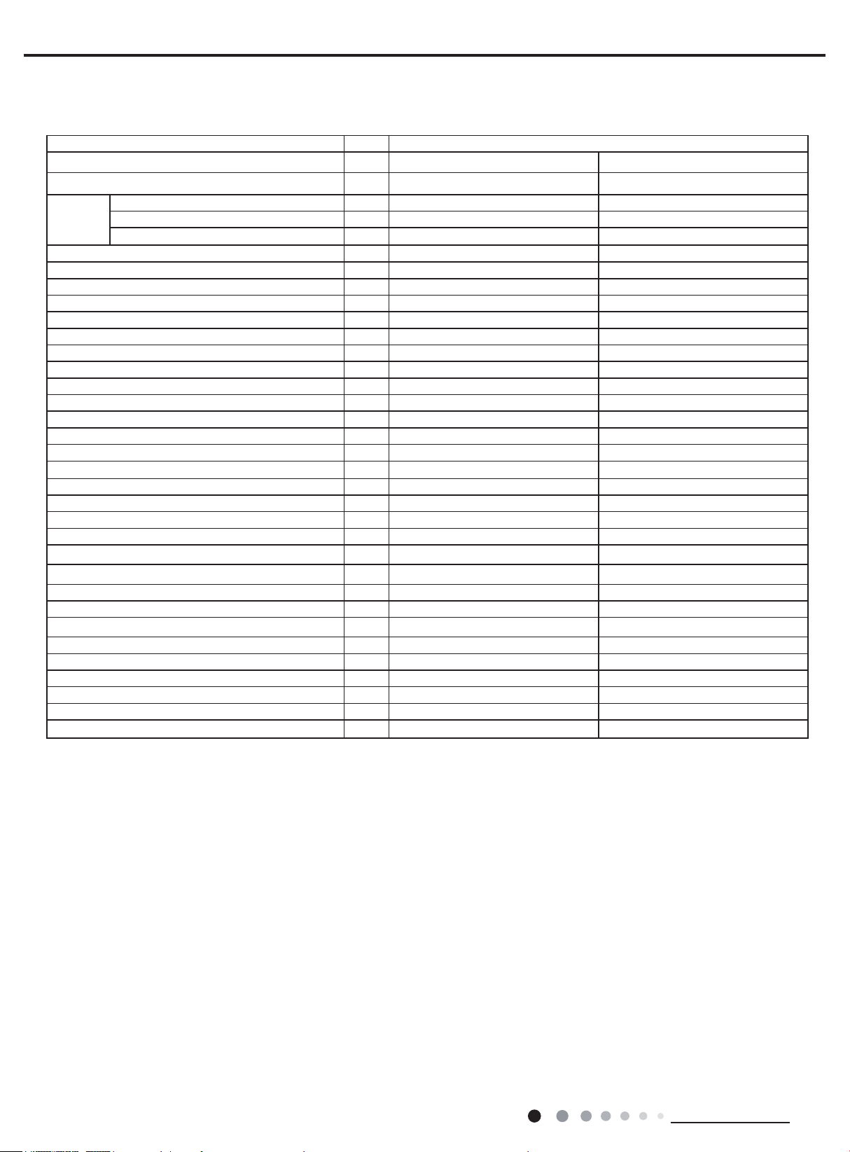
2. Specications
Parameter Unit Value
Model
Product Code CF022N1420 CF022N1400
Power
Supply
Cooling Capacity Btu/h 9000 12000
Heating Capacity Btu/h 9500 13000
Cooling Power Input KW 0.09 0.09
Heating Power Input KW 0.09 0.09
Cooling Current Input A 0.4 0.4
Heating Current Input A 0.4 0.4
Air ow volume(SH/H/M/L/SL) CFM 324/253/212/188/- 324/253/212/188/-
Dehumidifying Volume Pint/h 1.69 1.69
Fan Type Centrifugal Centrifugal
Fan Diameter-height inch Φ8~4 7/32 Φ8~4 7/32
Fan Motor Speed rpm 860/670/570/510 940/770/670/570
Fan Motor Power Output W 150 150
Fan Motor Power Input W / /
Motor Full Load Amp(FLA) A 0.4 0.4
Fan Motor Capacitor μF / /
Evaporator Material Aluminum n-copper tube Aluminum n-copper tube
Evaporator Pipe Diameter inch Φ5/16 Φ5/16
Evaporator Number of Rows-Fin Pitch - 2 2
Evaporator Length(L)XHeight(H)XWidth(W) inch 18 1/2X12 1/8X1/2 470X308X38
Fuse Current A 5 5
Sound Pressure Level(SH/H/M/L/SL) dB (A) 38/35/30/26/- 38/35/30/26/-
Sound Power Level(SH/H/M/L/SL) dB (A) 52/49/44/40/- 52/49/44/40/-
Dimension of Outline(LXWXH) inch 32 43/64X29 11/16X11 13/16 32 43/64X29 11/16X11 13/16
Dimension of Carton Box(LXWXH) inch 35 13/64X31 11/16X13 37/64 35 13/64X31 11/16X13 37/64
Dimension of Package(LXWXH) inch 35 5/16X31 13/16X14 11/16 35 5/16X31 13/16X14 11/16
Net Weight Ib 70.6 70.6
Gross Weight Ib 83.8 83.8
Liquid pipe
Gas Pipe(to indoor unit) inch Φ1/4 Φ1/4
Rated Voltage V~ 208/230 208/230
Rated Frequency Hz 60 60
Phases 1 1
inch Φ3/8 Φ1/2
DUCT09HP230V1BD DUCT12HP230V1BD
The above data is subject to change without notice. Please refer to the nameplate of the unit.
2
Technical Information
Service Manual
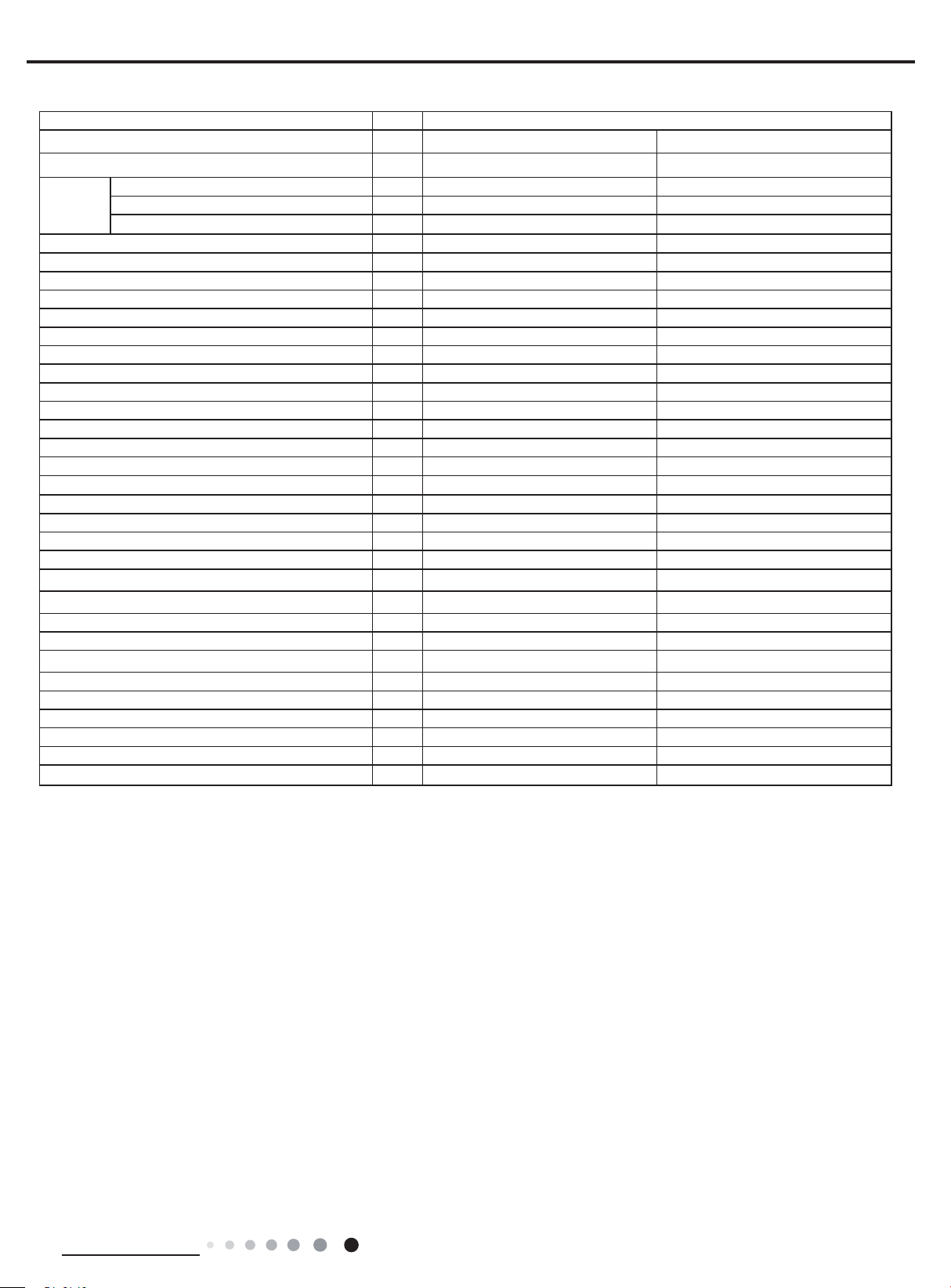
Parameter Unit Value
Model
Product Code CF022N1390 CF022N1410
Power
Supply
Cooling Capacity Btu/h 18000 21000
Heating Capacity Btu/h 19000 23000
Cooling Power Input KW 0.16 0.16
Heating Power Input KW 0.16 0.16
Cooling Current Input A 0.7 0.7
Heating Current Input A 0.7 0.7
Air ow volume(SH/H/M/L/SL) CFM 589/412/312/288/- 589/412/312/288/-
Dehumidifying Volume Pint/h 2 1.0
Fan Type Centrifugal Centrifugal
Fan Diameter-height inch Φ8~4 7/32 Φ8~4 7/32
Fan Motor Speed rpm 990/700/530/490 990/700/530/490
Fan Motor Power Output W 200 200
Fan Motor Power Input W / /
Motor Full Load Amp(FLA) A 0.7 0.7
Fan Motor Capacitor μF / /
Evaporator Material Aluminum n-copper tube Aluminum n-copper tube
Evaporator Pipe Diameter inch Φ5/16 Φ5/16
Evaporator Number of Rows-Fin Pitch - 3 3
Evaporator Length(L)XHeight(H)XWidth(W) inch 29 41/64X12 1/8X2 1/2 29 41/64X12 1/8X2 1/2
Fuse Current A 5 5
Sound Pressure Level(SH/H/M/L/SL) dB (A) 39/33/29/26/- 39/33/29/26/-
Sound Power Level(SH/H/M/L/SL) dB (A) 49/43/39/36/- 49/43/39/36/-
Dimension of Outline(LXWXH) inch 44 31/64X29 11/16X11 13/16 44 31/64X29 11/16X11 13/16
Dimension of Carton Box(LXWXH) inch 47 21/64X37 57/64X13 37/64 47 21/64X37 57/64X13 37/64
Dimension of Package(LXWXH) inch 47 7/16X32 1/64X14 11/64 47 7/16X32 1/64X14 11/64
Net Weight Ib 92.6 92.6
Gross Weight Ib 106.9 106.9
Liquid pipe
Gas Pipe(to indoor unit) inch Φ3/8 Φ3/8
Rated Voltage V~ 208/230 208/230
Rated Frequency Hz 60 60
Phases 1 1
inch Φ5/8 Φ5/8
DUCT18HP230V1BD GFH(21)DB-D3DNA1A/I
The above data is subject to change without notice. Please refer to the nameplate of the unit.
Technical Information
3
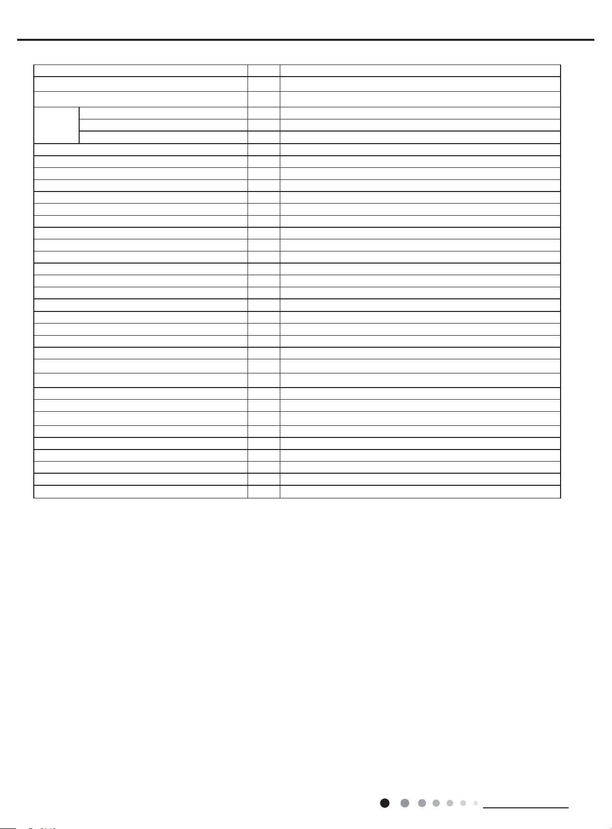
Parameter Unit Value
Model
Product Code CF022N1430
Power
Supply
Cooling Capacity Btu/h 24000
Heating Capacity Btu/h 27000
Cooling Power Input KW 0.21
Heating Power Input KW 0.21
Cooling Current Input A 0.9
Heating Current Input A 0.9
Air ow volume(SH/H/M/L/SL) CFM 736/559/453/406/-
Dehumidifying Volume Pint/h 2.5
Fan Type Centrifugal
Fan Diameter-height inch Φ8~4 7/32
Fan Motor Speed rpm 1050/800/650/580
Fan Motor Power Output W 200
Fan Motor Power Input W /
Motor Full Load Amp(FLA) A 0.7
Fan Motor Capacitor μF /
Evaporator Material Aluminum n-copper tube
Evaporator Pipe Diameter inch Φ5/16
Evaporator Number of Rows-Fin Pitch - 2
Evaporator Length(L)XHeight(H)XWidth(W) inch 29 41/64X12 1/8X2 1/2
Fuse Current A 5
Sound Pressure Level(SH/H/M/L/SL) dB (A) 39/33/29/26/-
Sound Power Level(SH/H/M/L/SL) dB (A) 49/43/39/36/-
Dimension of Outline(LXWXH) inch 44 31/64X29 11/16X11 13/16
Dimension of Carton Box(LXWXH) inch 47 21/64X37 57/64X13 37/64
Dimension of Package(LXWXH) inch 47 7/16X32 1/64X14 11/64
Net Weight Ib 92.6
Gross Weight Ib 106.9
Liquid pipe inch Φ5/8
Gas Pipe(to indoor unit) inch Φ3/8
The above data is subject to change without notice. Please refer to the nameplate of the unit.
Rated Voltage V~ 208/230
Rated Frequency Hz 60
Phases 1
DUCT24HP230V1BD
Service Manual
4
Technical Information
Service Manual
C
A
C
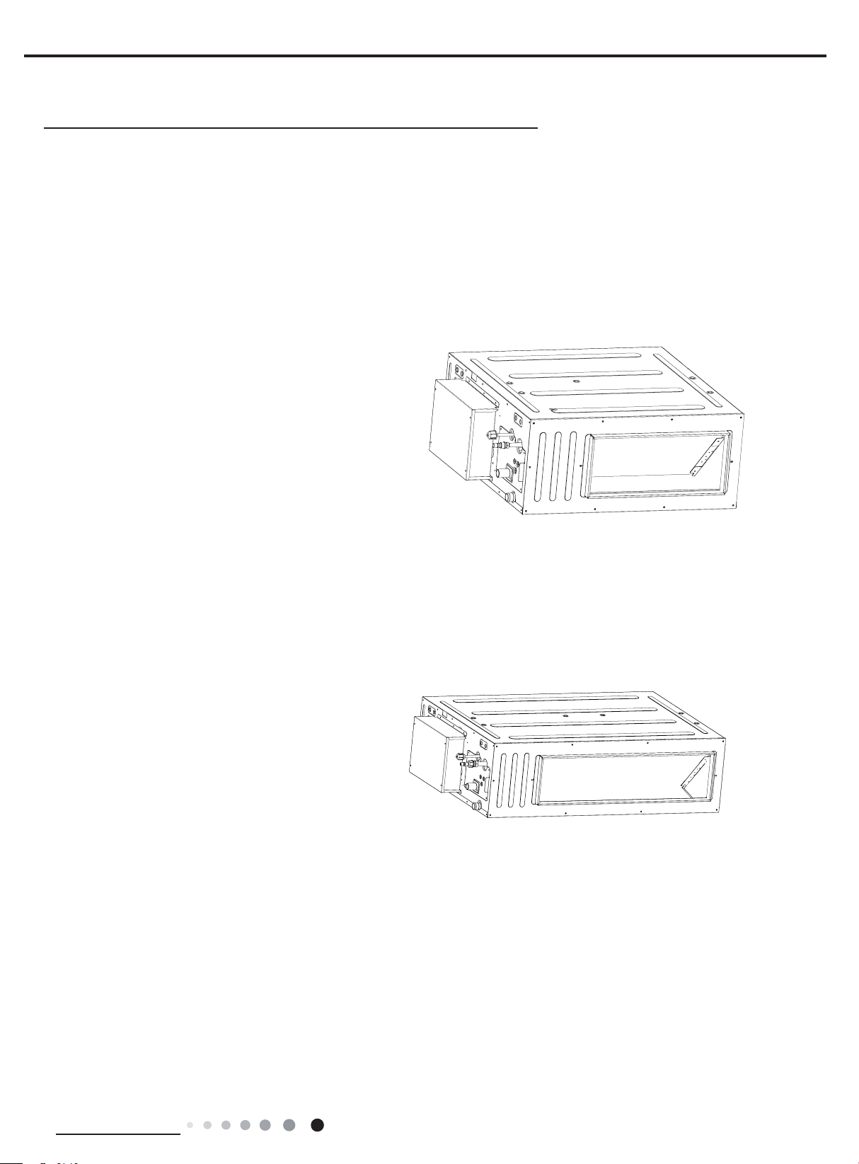
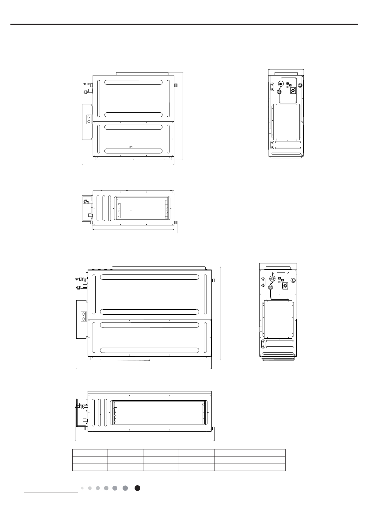
3. Outline Dimension Diagram
DUCT09HP230V1BD DUCT12HP230V1BD
D
B
E
A
DUCT18HP230V1BD GFH(21)DB-D3DNA1A/I DUCT24HP230V1BD
D
E
B
Technical Information
Model A B C D E
09/12K 32 43/64 29 11/16 11 13/16 31 11/32 27 9/16
18/21/24K 44 31/64 29 11/16 11 13/16 43 7/64 39 3/8
5
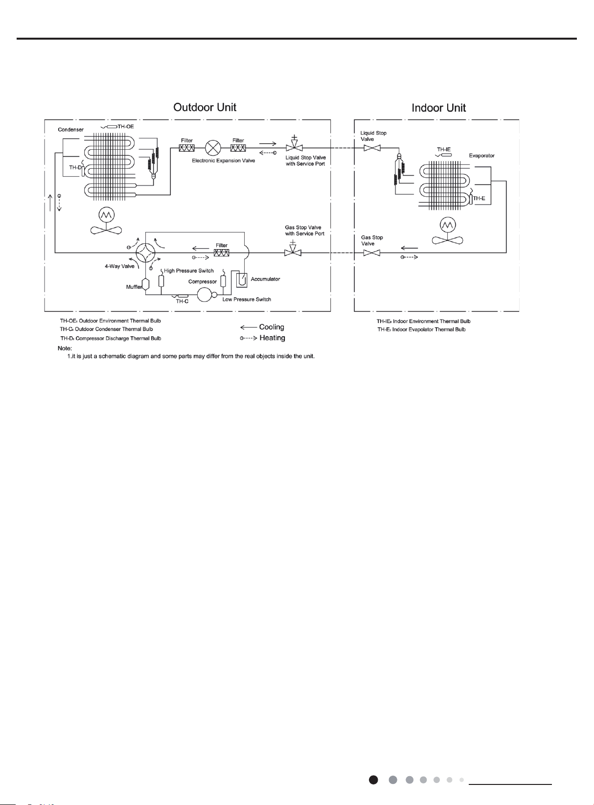
4. Refrigerant System Diagram
Service Manual
6
Technical Information
Service Manual
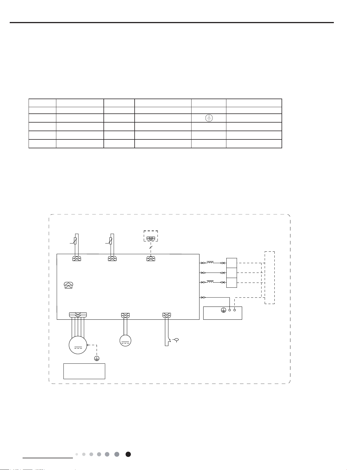
5. Electrical Part
5.1 Wiring Diagram
●Instruction
Symbol Symbol Color Symbol Symbol Color Symbol Name
WH White GN GREEN COMP Compressor
YE Yellow BN Brown Grouding wire
RD Red BU Blue
YEGN Yellow/Green BK Black
VT Violet OG Orange
● Outdoor Unit
78%(7(0352207(03
6(16256(1625
.
5220
&$3
.
$3φ35,17('&,5&8,7%2$5'
-803
'&02725
0
)$102725
1RWH0RWRUJURXQG
RQO\DSSOLHVWRWKH
LURQVKHOOPRWRU
*
78%(
&21752//(5
&200$18$/
0
:$7(53803
02725
:,5('
$3
:$7(5'7&73803
1δ1ε
&20287
$&/
/,48,'/(9(/
6:,7&+
0$*1(7,&
5,1*
3(
(/(&75,&%2;
7(50,1$/
%/2&.
/
%8
%.
/
%1
<(*1
*
:+%8
1
%.
5'%1
;7
*1<(*1
&211(&7,1*
,1'22581,7
600007060236
287'22581,7
&$%/(
These circuit diagrams are subject to change without notice, please refer to the one supplied with the unit.
Technical Information
7
12 3
11
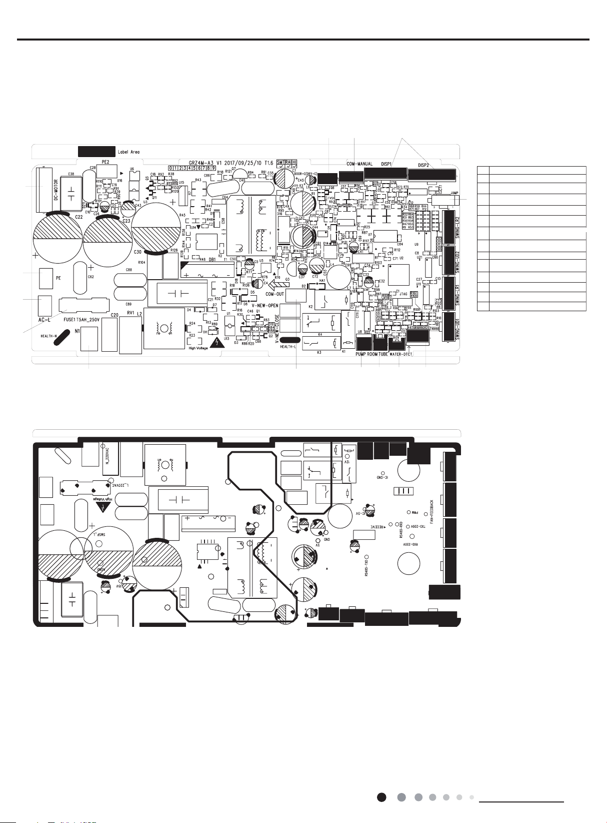
5.2 PCB Printed Diagram
TOP VIEW
●
14
13
12
Service Manual
12Interface of dry contact
Wired controlller terminal
3
Dispaly
4
Jumper cap
4
Water overflow protection
5
Interface of tube temperature sensor
6
Interface of ambient temperature
7
sensor
8
Water pump
Terminal with indoor unit communication
9
Neutral wire terminal
10
Fuse
11
Live wire terminal
12
Neutral wire terminal
13
Wiring terminal for DC motor
14
910
BOTTOM VIEW
●
5678
8
Technical Information
Service Manual
6. Function and Control
After putting through the power, air conditioner will give out a sound and indicators on control panel will be on. After that, you operate the
air conditioner through remote controller or control panel.
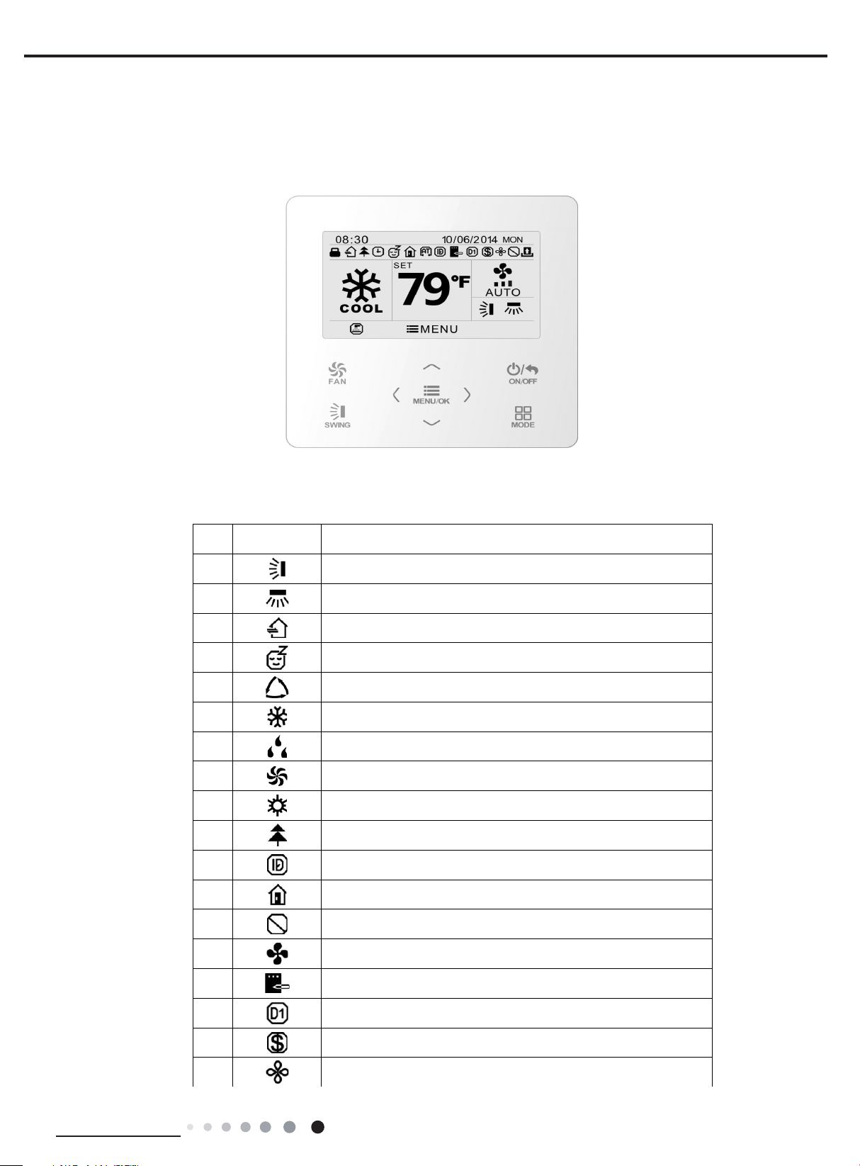
6.1 Introduction of Control Panel
1.1 Display
Fig.1 Appearance of wired controller
1.2 Instructions for Related Displayed Symbols
No. Symbols Instructions
1
2
3
4
5
6
7
8
9
10
11
12
13
14
15
16
Shielding status (Buttons, temperature, ON/OFF, mode or energy saving is
Up and down swing function
Left and right swing function
Fresh air function
Sleep function
Auto mode
Cooling mode
Dry mode
Fan mode
Heating mode
Health function
I-Demand function
Absence function
shielded by remote monitor)
Current set fan speed
Memory function (Memory in power failure)
DRED function
Technical Information
17
18
Save function
X-fan function
9
Service Manual
20
21
22
23
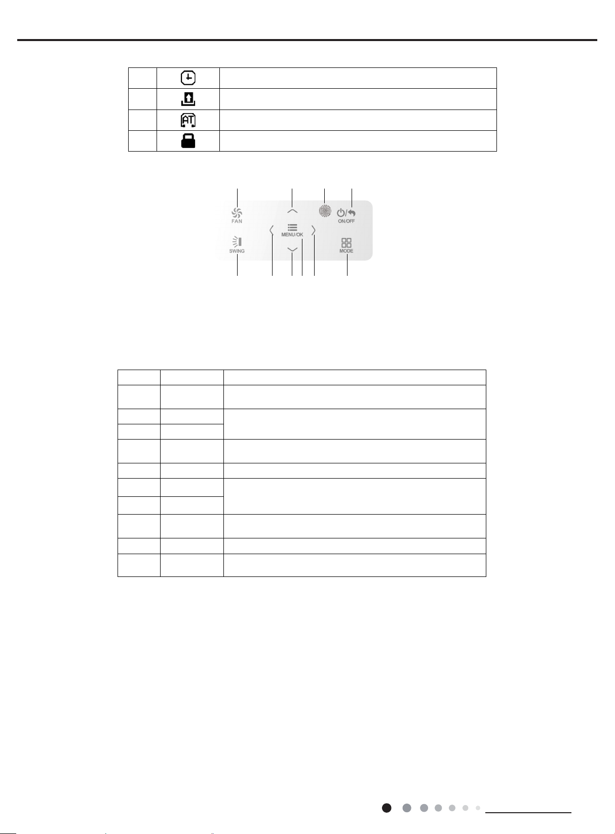
1.3 Button Grapics
1.4 Function Instructions of Buttons
Timer on status
Gate card pulled-off status or nobody presented status
Quiet function
Function lock
12 3
456
10
978
Fig. 2 Button graphics
No.Button name Button Function
1FAN
2
6
3ON/OFF/BACK
4SWING Setup&down swingand set left&right swing
5
8
7MENU/OK
9
10
∧
Z
¥
MODE Setauto, cooling, dry, fan and heating modes for indoor unit.
Remote control
receiver window
Set low speed, medium speed,high speed, turbo and auto speed.
(1) Set temperature
(2) Set parameter
(3) Move option cursor
(1) Turn on or turn off unit
(2) Return to last page
(1)Set relatedfunction on or off
(2) Move option cursor
(3)Set parameter
(1) Enter menu page
(2) Confirm setting
10
Technical Information

Service Manual
6.2 Introduction of Control Panel
1.Basic function of system
(1)Cooling mode
(1) Under this mode, fan and swing operates at setting status. Temperature setting range is 16~30OC.
(2) During malfunction of outdoor unit or the unit is stopped because of protection, indoor unit keeps original operation status.
(2)Drying mode
(1) Under this mode, fan operates at low speed and swing operates at setting status. Temperature setting range is 16~30OC.
(2) During malfunction of outdoor unit or the unit is stopped because of protection, indoor unit keeps original operation status.
(3) Protection status is same as that under cooling mode.
(4) Sleep function is not available for drying mode.
(3)Heating mode
(1) Under this mode, Temperature setting range is 16~30OC.
(2) Working condition and process for heating mode:
When turn on the unit under heating mode, indoor unit enters into cold air prevention status. When the unit is stopped or at OFF status,
and indoor unit has been started up just now, the unit enters into residual heat-blowing status.
(4)Working method for AUTO mode:
1.Working condition and process for AUTO mode:
a.Under AUTO mode, standard heating Tpreset=20OC and standard cooling Tpreset=25OC. The unit will switch mode automatically
according to ambient temperature.
2.Protection function
a. During cooling operation, protection function is same as that under cooling mode.
b. During heating operation, protection function is same as that under heating mode.
3. Display: Set temperature is the set value under each condition. Ambient temperature is (Tamb.-Tcompensation) for heat pump unit
and Tamb. for cooling only unit.
4. If theres I feel function, Tcompensation is 0. Others are same as above.
(5)Fan mode
Under this mode, indoor fan operates at set fan speed. Compressor, outdoor fan, 4-way valve and electric heating tube stop operation.
Indoor fan can select to operate at high, medium, low or auto fan speed. Temperature setting range is 16~30OC.
2. Other control
(1) Buzzer
Upon energization or availably operating the unit or remote controller, the buzzer will give out a beep.
(2) Auto button
If press this auto button when turning off the unit, the complete unit will operate at auto mode. Indoor fan operates at auto fan speed
and swing function is turned on. Press this auto button at ON status to turn off the unit.
(3) Auto fan
Heating mode: During auto heating mode or normal heating ode, auto fan speed will adjust the fan speed automatically according to
ambient temperature and set temperature.
(4) Sleep
After setting sleep function for a period of time, system will adjust set temperature automatically.
(5) Timer function:
General timer and clock timer functions are compatible by equipping remote controller with different functions.
(6) Memory function
memorize compensation temperature, off-peak energization value.
Memory content: mode, up&down swing, light, set temperature, set fan speed, general timer (clock timer cant be memorized).
After power recovery, the unit will be turned on automatically according to memory content.
(7) Health function(only for the model with this function)
During operation of indoor fan, set health function by remote controller. Turn off the unit will also turn off health function.
Turn on the unit by pressing auto button, and the health is defaulted ON.
Technical Information
11

Service Manual
(8)Off-peak energization function:
Adjust compressors minimum stop time. The original minimum stop time is 180s and then we change to:
The time interval between two start-ups of compressor cant be less than 180+T s(0≤T≤15). T is the variable of controller. Thats to say
the minimum stop time of compressor is 180s~195s. Read-in T into memory chip when refurbish the memory chip each time. After power
recovery, compressor can only be started up after 180+T s at least.
(9) SE control mode
The unit operates at SE status.
(10) X-fan mode
When X-fan function is turned on, after turn off the unit, indoor fan will still operate at low speed for 2min and then the complete unit will be
turned off. When x-fan function is turned off, after turn off the unit, the complete unit will be turned off directly.
(11) 8ºC heating function
Under heating mode, you can set 8ºC heating function by remote controller. The system will operate at 8ºC set temperature.
(12) Turbo fan control function
Set turbo function under cooling or heating mode to enter into turbo fan speed. Press fan speed button to cancel turbo wind.
No turbo function under auto, dry or fan mode.
12
Technical Information
Service Manual
Part
: Installation and Maintenance
Ⅱ
7. Notes for Installation and Maintenance
Safety Precautions:
Important!
Please read the safety precautions carefully before
installation and maintenance.
The following contents are very important for installation
and maintenance.
Please follow the instructions below.
●The installation or maintenance must accord with the
instructions.
●Comply with all national electrical codes and local
electrical codes.
●Pay attention to the warnings and cautions in this
manual.
●All installation and maintenance shall be performed by
distributor or qualied person.
●All electric work must be performed by a licensed
technician according to local regulations and the
instructions given in this manual.
●Be caution during installation and maintenance. Prohibit
incorrect operation to prevent electric shock, casualty and
other accidents.
Warnings
Electrical Safety Precautions:
1. Cut off the power supply of air conditioner before
checking and maintenance.
2. The air condition must apply specialized circuit and
prohibit share the same circuit with other appliances.
3. The air conditioner should be installed in suitable
location and ensure the power plug is touchable.
4. Make sure each wiring terminal is connected firmly
during installation and maintenance.
5. Have the unit adequately grounded. The grounding wire
cant be used for other purposes.
6. Must apply protective accessories such as protective
boards, cable-cross loop and wire clip.
7. The live wire, neutral wire and grounding wire of power
supply must be corresponding to the live wire, neutral
wire and grounding wire of the air conditioner.
8. The power cord and power connection wires cant be
pressed by hard objects.
9. If power cord or connection wire is broken, it must be
replaced by a qualied person.
10. If the power cord or connection wire is not long enough,
please get the specialized power cord or connection wire
from the manufacture or distributor. Prohibit prolong the wire
by yourself.
11. For the air conditioner without plug, an air switch must
be installed in the circuit. The air switch should be all-pole
parting and the contact parting distance should be more than
1/8 inch.
12. Make sure all wires and pipes are connected properly and
the valves are opened before energizing.
13. Check if there is electric leakage on the unit body. If yes,
please eliminate the electric leakage.
14. Replace the fuse with a new one of the same specication
if it is burnt down; dont replace it with a cooper wire or
conducting wire.
15. If the unit is to be installed in a humid place, the circuit
breaker must be installed.
Installation Safety Precautions:
1. Select the installation location according to the requirement of this manual.(See the requirements in installation
part)
2. Handle unit transportation with care; the unit should not
be carried by only one person if it is more than 44.09lb.
3. When installing the indoor unit and outdoor unit, a sufcient xing bolt must be installed; make sure the installation
support is rm.
4. Ware safety belt if the height of working is above 78 3/4
inch.
5. Use equipped components or appointed components during installation.
6. Make sure no foreign objects are left in the unit after nishing installation.
Refrigerant Safety Precautions:
1. Avoid contact between refrigerant and re as it generates
poisonous gas; Prohibit prolong the connection pipe by
welding.
2. Apply specied refrigerant only. Never have it mixed with
any other refrigerant. Never have air remain in the refrigerant
line as it may lead to rupture or other hazards.
3. Make sure no refrigerant gas is leaking out when installation
is completed.
4. If there is refrigerant leakage, please take sufcient measure
to minimize the density of refrigerant.
5. Never touch the refrigerant piping or compressor without
wearing glove to avoid scald or frostbite.
Improper installation may lead to re hazard, explosion,
electric shock or injury.
Installation and Maintenance
13
Service Manual
Safety Precautions for Installing and Relocating the Unit:
To ensure safety, please be mindful of the following precautions.
Warnings
1. When installing or relocating the unit, be sure to keep the refrigerant circuit free from air or substances other than the
specied refrigerant.
Any presence of air or other foreign substance in the refrigerant circuit will cause system pressure rise or compressor rupture, resulting in
injury.
2.When installing or moving this unit, do not charge the refrigerant which is not comply with that on the nameplate or
unqualied refrigerant.
Otherwise, it may cause abnormal operation, wrong action, mechanical malfunction or even series safety accident.
3.When refrigerant needs to be recovered during relocating or repairing the unit, be sure that the unit is running in cooling
mode.Then, fully close the valve at high pressure side (liquid valve).About 30-40 seconds later, fully close the valve at low
pressure side (gas valve), immediately stop the unit and disconnect power. Please note that the time for refrigerant recovery
should not exceed 1 minute.
If refrigerant recovery takes too much time, air may be sucked in and cause pressure rise or compressor rupture, resulting in injury.
4.During refrigerant recovery, make sure that liquid valve and gas valve are fully closed and power is disconnected before
detaching the connection pipe.
If compressor starts running when stop valve is open and connection pipe is not yet connected, air will be sucked in and cause pressure
rise or compressor rupture, resulting in injury.
5.When installing the unit, make sure that connection pipe is securely connected before the compressor starts running.
If compressor starts running when stop valve is open and connection pipe is not yet connected, air will be sucked in and cause pressure
rise or compressor rupture, resulting in injury.
6.Prohibit installing the unit at the place where there may be leaked corrosive gas or ammable gas.
If there leaked gas around the unit, it may cause explosion and other accidents.
7.Do not use extension cords for electrical connections. If the electric wire is not long enough, please contact a local service
center authorized and ask for a proper electric wire.
Poor connections may lead to electric shock or re.
8.Use the specied types of wires for electrical connections between the indoor and outdoor units. Firmly clamp the wires so
that their terminals receive no external stresses.
Electric wires with insufcient capacity, wrong wire connections and insecure wire terminals may cause electric shock or re.
14
Installation and Maintenance
 Loading...